EP4395136A1 - Stator - Google Patents
Stator Download PDFInfo
- Publication number
- EP4395136A1 EP4395136A1 EP22861429.3A EP22861429A EP4395136A1 EP 4395136 A1 EP4395136 A1 EP 4395136A1 EP 22861429 A EP22861429 A EP 22861429A EP 4395136 A1 EP4395136 A1 EP 4395136A1
- Authority
- EP
- European Patent Office
- Prior art keywords
- stator
- housing
- circuit board
- printed circuit
- flexible printed
- Prior art date
- Legal status (The legal status is an assumption and is not a legal conclusion. Google has not performed a legal analysis and makes no representation as to the accuracy of the status listed.)
- Pending
Links
Images



Classifications
-
- H—ELECTRICITY
- H02—GENERATION; CONVERSION OR DISTRIBUTION OF ELECTRIC POWER
- H02K—DYNAMO-ELECTRIC MACHINES
- H02K3/00—Details of windings
- H02K3/04—Windings characterised by the conductor shape, form or construction, e.g. with bar conductors
- H02K3/26—Windings characterised by the conductor shape, form or construction, e.g. with bar conductors consisting of printed conductors
-
- H—ELECTRICITY
- H02—GENERATION; CONVERSION OR DISTRIBUTION OF ELECTRIC POWER
- H02K—DYNAMO-ELECTRIC MACHINES
- H02K3/00—Details of windings
- H02K3/46—Fastening of windings on the stator or rotor structure
- H02K3/52—Fastening salient pole windings or connections thereto
- H02K3/521—Fastening salient pole windings or connections thereto applicable to stators only
- H02K3/522—Fastening salient pole windings or connections thereto applicable to stators only for generally annular cores with salient poles
-
- H—ELECTRICITY
- H02—GENERATION; CONVERSION OR DISTRIBUTION OF ELECTRIC POWER
- H02K—DYNAMO-ELECTRIC MACHINES
- H02K2203/00—Specific aspects not provided for in the other groups of this subclass relating to the windings
- H02K2203/03—Machines characterised by the wiring boards, i.e. printed circuit boards or similar structures for connecting the winding terminations
Definitions
- a motor mounting on the devices is required to be further reduced in size and thickness.
- a stator of the motor is configured by winding a coil around a soft magnetic core.
- Patent Document 1 below discloses a technique for reducing the motor in size by configuring a stator using a flexible printed circuit board including a coil.
- Patent Literature 1 Japanese Patent Application Publication No. 1994-253481
- stator further includes teeth provided on the inner surface of the housing and made of a soft magnetic material, wherein the print coil wiring is disposed around the teeth.
- an internal diameter of the housing is 3mm or less.
- stator further includes a flexible printed circuit board provided with the print coil wiring, wherein the flexible printed circuit board is attached to the inner surface of the housing.
- a thickness of the flexible printed circuit board is 500 ⁇ m or less.
- a main component of a base material of the flexible printed circuit board is polyimide resin, PET resin, or LCP resin.
- a base material of the flexible printed circuit board is made of magnetic powder-containing resin.
- the stator further includes a soft magnetic body and a flexible printed circuit board provided on a main surface of the soft magnetic body and provided with a printed coil wiring.
- a stator improving motor torque is provided.
- the motor 1 consists of a rotor 10 having a shaft 11 and a magnet 12, and a stator 20.
- the magnet 12 in the rotor 10 is formed partially or wholly on the outer circumferential surface of the shaft 11, and disposed on the inner peripheral side of the stator 20 with a gap.
- the motor 1 is a micromotor designed to have, for example, a length between both ends of the shaft 11 of 4 to 30mm (15mm as an example) and an outer diameter of the stator 20 of 0.5 to 5mm (2mm as an example).
- the configuration of the rotor 10 according to the present embodiment can be realized by covering the outer circumferential surface of the shaft 11 made of metal (for example, Co) with a thin-film magnet (for example, SmCo 5 ) formed by using a molten salt immersion method or the like.
- metal for example, Co
- a thin-film magnet for example, SmCo 5
- the housing 22 has a cylindrical shape.
- the housing 22 according to the present embodiment is designed to have, for example, an outer diameter of 0.5 to 5mm (2mm as an example), an internal diameter of 0.3 to 3mm (1.8mm as an example), a thickness of 0.05 to 0.2mm (0.1mm as an example), and a length of 4 to 30mm (14mm as an example).
- the housing 22 is made of a soft magnetic material, and may be made of, for example, ferritic stainless steel (SUS430 or the like), an electromagnetic steel plate, permalloy, or nickel.
- the flexible printed circuit board 24 includes a sheet-like base material 26 and a plurality of print coil wiring 28 provided on the base material 26.
- a thickness of the flexible printed circuit board 24 is, for example, 20 to 500 ⁇ m (100 ⁇ m as an example).
- the base material 26 has a rectangular shape and has a length L (axial length) and a width W (circumferential length).
- the length L is designed to be equal to or less than the length of the housing 22, and is, for example, 12mm.
- the width W is designed to be approximately the same as (or slightly shorter than) the circumference of the inner surface 22a of the housing 22.
- a thickness of the base material 26 is, for example, 5 to 100 ⁇ m (12 ⁇ m as an example).
- the base material 26 is made of a non-magnetic material.
- the base material 26 includes resin such as polyimide resin, PET resin, or LCP resin as a main component.
- the main component of the base material 26 is a material having a high elastic modulus such as polyimide resin
- the flexible printed circuit board 24 since the flexible printed circuit board 24 has high rigidity, a large restoring force is generated when the base material 26 is rolled, and thus the flexible printed circuit board 24 can be firmly affixed to the inner surface 22a of the housing 22 by the restoring force.
- the main component of the base material 26 is a material having a low elastic modulus such as PET resin
- the flexible printed circuit board 24 has high flexibility and thus can be easily rolled, and the small-sized stator 20 having a small radius can be formed.
- the main component of the base material 26 is a material excellent in shape retention or a thermoplastic material such as LCP resin
- the shape of the base material 26 is easily held in a cylindrical shape, and thus the work in manufacturing the stator 20 is facilitated.
- the plural print coil wiring 28 (three print coil wiring in the present embodiment) are provided on the main surface 26a of the base material 26.
- the print coil wiring 28 can be formed by patterning a copper foil, for example.
- the print coil wiring 28 has 3 to 100 ⁇ m (12 ⁇ m as an example) thickness and 10 to 300 ⁇ m (35 ⁇ m as an example) width.
- the number of print coil wiring 28A, 28B, and 28C i.e., three in the present embodiment
- the number of turns of each print coil wiring 28A, 28B, and 28C can be increased (for example, 10 to 30 turns) or decreased as appropriate.
- Each of the print coil wiring 28A, 28B, and 28C is an elongated coreless coil extending in the longitudinal direction of the base material 26 (corresponding to the axial direction D A when the base material 26 is rolled).
- the print coil wiring 28A, 28B, and 28C have substantially the same shape and dimensions.
- Three print coil wiring 28A, 28B, and 28C are arranged at predetermined intervals along the widthwise direction of the base material 26 (corresponding to the circumferential direction D C when the base material 26 is rolled).
- Each the print coil wiring 28A, 28B, and 28C is electrically connected to a control circuit (not shown) via each outer end portion 28a, and a predetermined current can be applied from the control circuit to each the print coil wiring 28A, 28B, and 28C.
- the flexible printed circuit board 24 is rolled in the circumferential direction Dc so that the main surface 26a of the base material 26 provided with the print coil wiring 28 is located inside, and is housed in the housing 22. Then, due to the restoring force of the flexible printed circuit board 24, the flexible printed circuit board 24 is affixed to the inner surface 22a of the housing 22 and fixed in position. As a result, three the print coil wiring 28A, 28B, and 28C are arranged inside the stator 20 along the circumferential direction. By setting the width W of the base material 26 to be substantially the same as the circumferential length of the inner surface 22a of the housing 22, one roll of the flexible printed circuit board 24 is fitted in the housing 22.
- the housing 22 of the stator 20 is made of soft magnetic material, magnetic resistance decreases, and interlinkage magnetic fluxes of the print coil wiring 28A, 28B, and 28C increase. Therefore, high rotational torque is realized in the motor 1 to which the stator 20 is applied.
- the stator 20 and the motor 1 can be downsized.
- the thickness of the base material 26 is 100 ⁇ m or less, a small motor that is sufficiently small for practical use can be obtained.
- the inventors measured the torque of a plurality of samples having different thicknesses of the base material even in a case where magnetic powder is contained in the base material of the flexible printed circuit board.
- the results are shown in Tables 2 and 3 below.
- the main component of the base material is polyimide resin, and the base material contains magnetic powder (in particular, soft magnetic ferrite powder).
- the permeability (relative permeability) of the base material was 20 for Samples 7 to 12 shown in Table 2 and was 50 for Samples 13 to 18 shown in Table 3.
- the permeability was measured using an impedance analyzer (KEYSIGHT E4990A).
- the magnetic powder contained in the base material may be, for example, metal soft magnetic powder or ferrite soft magnetic powder.
- the flexible printed circuit board 24 may have the print coil wiring 28 on both surfaces, and the print coil wiring on both surfaces may be conducted in series via a through hole. Since the number of turns of the coil increases, a higher rotational torque can be realized as the motor.
- the print coil wiring 28A, 28B, and 28C may be directly provided on the inner surface 22a of a housing 22A.
- the housing 22A can be made of soft magnetic material having flexibility (for example, magnetic powder-containing resin).
- the magnetic powder contained in the housing 22A may be, for example, metal soft magnetic powder or ferrite soft magnetic powder.
- the housing 22A may be rolled into a cylindrical shape.
- the housing 22A since the housing 22A is made of soft magnetic material having small magnetic resistance, interlinkage magnetic fluxes of the print coil wiring 28A, 28B, and 28C increase. Therefore, it is possible to realize a higher rotational torque by applying it to the motor 1.
- the housing 22A may be entirely made of soft magnetic material, or may be partially made of non-magnetic material and the remaining part made of soft magnetic material.
- teeth 23 may be provided on the inner surface 22a of a housing 22B.
- the teeth 23 rise from the inner surface 22a of the housing 22B and is provided integrally with the housing 22B.
- the teeth 23 are provided in the same number (three in the present embodiment) as the print coil wiring 28A, 28B, and 28C.
- Each of the print coil wiring 28A, 28B, and 28C is disposed around each of the teeth 23.
- the height of the teeth 23 is, for example, 10 to 100 ⁇ m (15 ⁇ m as an example), and may be the same as or higher than the height of the print coil wiring 28.
- the teeth 23 may be in the form of ribs extending parallel to the print coil wiring 28A, 28B and 28C. According to the configuration shown in FIG.
- the teeth may be separate from the housing, or may be made of magnetic material different from the magnetic material forming the housing.
- the teeth may be formed by screen-printing resin containing magnetic powder, or may be formed by plating nickel. In either case, if the teeth are made of the same material as that of the print coil wiring, the number of steps for manufacturing the stator can be reduced.
- the housing 22B may be entirely made of soft magnetic material, or may be partially made of non-magnetic material and the remaining part made of soft magnetic material.
- a stator used in a motor including a magnetized shaft-shaped rotor and a cylindrical stator, and the rotor is inserted through the stator, the stator comprising:
- the stator according to Appendix 1 further comprising teeth provided on the inner surface of the housing and made of a soft magnetic material, wherein the print coil wiring is disposed around the teeth.
- stator according to any one of Appendixes 1 to 3 further comprising a flexible printed circuit board provided with the print coil wiring, wherein the flexible printed circuit board is attached to the inner surface of the housing.
Landscapes
- Engineering & Computer Science (AREA)
- Power Engineering (AREA)
- Permanent Magnet Type Synchronous Machine (AREA)
- Iron Core Of Rotating Electric Machines (AREA)
Abstract
Description
- The present disclosure relates to a stator used in a motor.
- According to reduction in size and thickness of devices, a motor mounting on the devices is required to be further reduced in size and thickness. Generally, a stator of the motor is configured by winding a coil around a soft magnetic core.
Patent Document 1 below discloses a technique for reducing the motor in size by configuring a stator using a flexible printed circuit board including a coil. - Patent Literature 1:
Japanese Patent Application Publication No. 1994-253481 - In the above-described stator according to the background art, the base material constituting the flexible printed circuit board is made of a non-magnetic material such as polyimide resin. The non-magnetic material has high magnetic resistance and magnetic fluxes are difficult to pass through the non-magnetic material. Therefore, it is difficult to obtain a practically sufficient motor torque.
- It is an object of the present disclosure to provide a stator capable of improving motor torque.
- A stator according to an aspect of the present disclosure is used in a motor including a magnetized shaft-shaped rotor and a cylindrical stator, and the rotor is inserted through the stator, the stator includes a cylindrical housing made of a soft magnetic material, and print coil wiring provided on an inner surface of the housing.
- In the stator, the magnetic resistance of the magnetic path of the motor decreases due to the housing made of a soft magnetic material, and the magnetic flux interlinking the printed coil increases. Therefore, the motor torque can be improved by applying the stator to the motor.
- In a stator according to another aspect, the stator further includes teeth provided on the inner surface of the housing and made of a soft magnetic material, wherein the print coil wiring is disposed around the teeth.
- In a stator according to another aspect, an internal diameter of the housing is 3mm or less.
- In a stator according to another aspect, the stator further includes a flexible printed circuit board provided with the print coil wiring, wherein the flexible printed circuit board is attached to the inner surface of the housing.
- In a stator according to another aspect, a thickness of the flexible printed circuit board is 500µm or less.
- In a stator according to another aspect, a main component of a base material of the flexible printed circuit board is polyimide resin, PET resin, or LCP resin.
- In a stator according to another aspect, a base material of the flexible printed circuit board is made of magnetic powder-containing resin.
- In a stator according to another aspect, the stator further includes a soft magnetic body and a flexible printed circuit board provided on a main surface of the soft magnetic body and provided with a printed coil wiring.
- According to the present disclosure, a stator improving motor torque is provided.
-
-
FIG. 1 is a schematic perspective view of a motor according to one embodiment. -
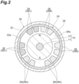
FIG. 2 is a cross-sectional view taken along line II-II of the motor shown inFIG. 1 . -
FIG. 3 is a developed view of the flexible printed circuit board shown inFIG. 2 . -
FIG. 4 is a cross-sectional view showing a different embodiment. -
FIG. 5 is a cross-sectional view showing a different embodiment. -
FIG. 6 is a cross-sectional view showing a different embodiment. -
FIG. 7 is a cross-sectional view showing a different embodiment. - Hereinafter, embodiments of the present disclosure will be described in detail with reference to the accompanying drawings. In the description, the same reference numerals are used for the same elements or elements having the same functions, and redundant description will be omitted.
- First, the configuration of a
motor 1 according to one embodiment will be described with reference toFIGS. 1 and2 . - The
motor 1 consists of arotor 10 having ashaft 11 and amagnet 12, and astator 20. Themagnet 12 in therotor 10 is formed partially or wholly on the outer circumferential surface of theshaft 11, and disposed on the inner peripheral side of thestator 20 with a gap. Themotor 1 is a micromotor designed to have, for example, a length between both ends of theshaft 11 of 4 to 30mm (15mm as an example) and an outer diameter of thestator 20 of 0.5 to 5mm (2mm as an example). - The
rotor 10 has a shaft-like outer shape elongated in one direction and has an axis (rotational axis) parallel to the extending direction. In the present embodiment, theshaft 11 has an elongated columnar shape. Themagnet 12 has a cylindrical shape surrounding the outer circumferential surface of theshaft 11. Themagnet 12 is magnetized in the radial direction along the axis of easy magnetization. As shown inFIG. 2 , themagnet 12 may be configured to have two poles on its surface, or may be configured to have four poles or eight poles on its surface. The configuration of therotor 10 according to the present embodiment can be realized by covering the outer circumferential surface of theshaft 11 made of metal (for example, Co) with a thin-film magnet (for example, SmCo5) formed by using a molten salt immersion method or the like. - The
stator 20 has a cylindrical outer shape through which therotor 10 can be inserted. As shown inFIG. 2 , thestator 20 includes ahousing 22 andprint coil wiring 28 provided in thehousing 22. In the present embodiment, theprint coil wiring 28 is provided in thehousing 22 in the form of a flexible printedcircuit board 24. - The
housing 22 has a cylindrical shape. Thehousing 22 according to the present embodiment is designed to have, for example, an outer diameter of 0.5 to 5mm (2mm as an example), an internal diameter of 0.3 to 3mm (1.8mm as an example), a thickness of 0.05 to 0.2mm (0.1mm as an example), and a length of 4 to 30mm (14mm as an example). Thehousing 22 is made of a soft magnetic material, and may be made of, for example, ferritic stainless steel (SUS430 or the like), an electromagnetic steel plate, permalloy, or nickel. - As shown in
FIG. 3 , the flexibleprinted circuit board 24 includes a sheet-like base material 26 and a plurality ofprint coil wiring 28 provided on thebase material 26. A thickness of the flexible printedcircuit board 24 is, for example, 20 to 500µm (100µm as an example). - The
base material 26 has a rectangular shape and has a length L (axial length) and a width W (circumferential length). The length L is designed to be equal to or less than the length of thehousing 22, and is, for example, 12mm. The width W is designed to be approximately the same as (or slightly shorter than) the circumference of theinner surface 22a of thehousing 22. A thickness of thebase material 26 is, for example, 5 to 100µm (12µm as an example). Thebase material 26 is made of a non-magnetic material. Thebase material 26 includes resin such as polyimide resin, PET resin, or LCP resin as a main component. In the case where the main component of thebase material 26 is a material having a high elastic modulus such as polyimide resin, since the flexible printedcircuit board 24 has high rigidity, a large restoring force is generated when thebase material 26 is rolled, and thus the flexible printedcircuit board 24 can be firmly affixed to theinner surface 22a of thehousing 22 by the restoring force. In the case where the main component of thebase material 26 is a material having a low elastic modulus such as PET resin, the flexible printedcircuit board 24 has high flexibility and thus can be easily rolled, and the small-sized stator 20 having a small radius can be formed. In addition, when the main component of thebase material 26 is a material excellent in shape retention or a thermoplastic material such as LCP resin, the shape of thebase material 26 is easily held in a cylindrical shape, and thus the work in manufacturing thestator 20 is facilitated. - The plural print coil wiring 28 (three print coil wiring in the present embodiment) are provided on the
main surface 26a of thebase material 26. Theprint coil wiring 28 can be formed by patterning a copper foil, for example. Theprint coil wiring 28 has 3 to 100µm (12µm as an example) thickness and 10 to 300µm (35µm as an example) width. The number ofprint coil wiring print coil wiring print coil wiring base material 26 is rolled). Theprint coil wiring print coil wiring base material 26 is rolled). Each theprint coil wiring outer end portion 28a, and a predetermined current can be applied from the control circuit to each theprint coil wiring print coil wiring inner end portion 28b, and theprint coil wiring outer end portion 28a and theinner end portion 28b of theprint coil wiring print coil wiring - As shown in
FIG. 2 , the flexible printedcircuit board 24 is rolled in the circumferential direction Dc so that themain surface 26a of thebase material 26 provided with theprint coil wiring 28 is located inside, and is housed in thehousing 22. Then, due to the restoring force of the flexible printedcircuit board 24, the flexible printedcircuit board 24 is affixed to theinner surface 22a of thehousing 22 and fixed in position. As a result, three theprint coil wiring stator 20 along the circumferential direction. By setting the width W of thebase material 26 to be substantially the same as the circumferential length of theinner surface 22a of thehousing 22, one roll of the flexible printedcircuit board 24 is fitted in thehousing 22. - In the
above motor 1, by applying current to theprint coil wiring rotor 10 rotates around the axis. At this time, magnetic fluxes are generated around theprint coil wiring - In the
above motor 1, since thehousing 22 of thestator 20 is made of soft magnetic material, magnetic resistance decreases, and interlinkage magnetic fluxes of theprint coil wiring motor 1 to which thestator 20 is applied. - As the internal diameter of the
housing 22 of thestator 20 decreases, the deformation amount of the flexible printedcircuit board 24 accommodated in thehousing 22 increases and the restoring force of the flexible printedcircuit board 24 increases. When the internal diameter of thehousing 22 is 3mm or less, the flexible printedcircuit board 24 is firmly affixed to theinner surface 22a of thehousing 22 by a large restoring force. - By thinning the
base material 26 of the flexible printedcircuit board 24, thestator 20 and themotor 1 can be downsized. When the thickness of thebase material 26 is 100µm or less, a small motor that is sufficiently small for practical use can be obtained. - In order to find out the relationship between the thickness of the base material of the flexible printed circuit board and the torque, the inventors measured the torque for a plurality of samples having different thicknesses of the base material. The results are shown in Table 1 below. The main component of the base material is polyimide resin, and no magnetic powder is contained in the base material. Six print coil wiring were provided on the main surface of the base material. The magnet used in the experiment had four poles on the surface and was magnetized in the radial direction along the axis of easy magnetization. The shaft of the rotor was made of Co, and the outer circumferential surface of the shaft was covered with a thin-film magnet (in particular, SmCo5 magnet formed by using a molten salt immersion method) that was not in direct contact with the outer circumferential surface. The magnetic film had a thickness of 100µm, a length of 10mm in the axial direction, and an external diameter of 10mm. The housing was made of stainless steel (SUS430 [JIS]), and had a thickness of 0.2mm and an internal diameter of 3mm.
Table 1 Thickness of base material Torque Inner diameter of magnetic film Outer diameter of shaft [µm] [*10-6N/m] [mm] [mm] Sample 112.5 0.430 2.2 2.1 Sample 2 50 0.355 2.1 2 Sample 3 100 0.298 2 1.9 Sample 4 200 0.222 1.8 1.7 Sample 5 500 0.117 1.2 1.1 Sample 6 550 0.106 1.1 1 - In addition, the inventors measured the torque of a plurality of samples having different thicknesses of the base material even in a case where magnetic powder is contained in the base material of the flexible printed circuit board. The results are shown in Tables 2 and 3 below. The main component of the base material is polyimide resin, and the base material contains magnetic powder (in particular, soft magnetic ferrite powder). The permeability (relative permeability) of the base material was 20 for Samples 7 to 12 shown in Table 2 and was 50 for Samples 13 to 18 shown in Table 3. The permeability was measured using an impedance analyzer (KEYSIGHT E4990A).
[Table 2] Thickness of base material [µm] Torque [*10-6N/m] Inner diameter of magnetic film [mm] Outer diameter of shaft [mm] Sample 7 12.5 0.448 2.2 2.1 Sample 8 50 0.412 2.1 2 Sample 9 100 0.392 2 1.9 Sample 10200 0.353 1.8 1.7 Sample 11500 0.232 1.2 1.1 Sample 12550 0.180 1.1 1 [Table 3] Thickness of base material Torque Inner diameter of magnetic film Outer diameter of shaft [µm] [*10-6N/m] [mm] [mm] Sample 13 12.5 0.449 2.2 2.1 Sample 14 50 0.417 2.1 2 Sample 15 100 0.400 2 1.9 Sample 16 200 0.364 1.8 1.7 Sample 17 500 0.241 1.2 1.1 Sample 18 550 0.185 1.1 1 - As shown in Tables 1 to 3, it was established that the torque was improved as the base material of the flexible printed circuit board was thinner. In particular, when the base material of the flexible printed circuit board contains or does not contain magnetic powder, it was established that the thinner the base material is, the more the torque is improved. In the case that the base material of the flexible printed circuit board contained magnetic powder, it was established that the torque significantly decreased when the base material was thicker than 500µm as in the case of
Samples 12 and 18. The magnetic powder contained in the base material may be, for example, metal soft magnetic powder or ferrite soft magnetic powder. - The present disclosure is not limited to the above-described embodiment and can be modified in various ways.
- For example, the flexible printed
circuit board 24 may have theprint coil wiring 28 on both surfaces, and the print coil wiring on both surfaces may be conducted in series via a through hole. Since the number of turns of the coil increases, a higher rotational torque can be realized as the motor. - For example, as shown in
FIG. 4 , theprint coil wiring inner surface 22a of ahousing 22A. In this case, thehousing 22A can be made of soft magnetic material having flexibility (for example, magnetic powder-containing resin). The magnetic powder contained in thehousing 22A may be, for example, metal soft magnetic powder or ferrite soft magnetic powder. For example, after theprint coil wiring housing 22A in a sheet state, thehousing 22A may be rolled into a cylindrical shape. According to the embodiment shown inFIG. 4 , since thehousing 22A is made of soft magnetic material having small magnetic resistance, interlinkage magnetic fluxes of theprint coil wiring motor 1. Thehousing 22A may be entirely made of soft magnetic material, or may be partially made of non-magnetic material and the remaining part made of soft magnetic material. - Further, as shown in
FIG. 5 ,teeth 23 may be provided on theinner surface 22a of ahousing 22B. Theteeth 23 rise from theinner surface 22a of thehousing 22B and is provided integrally with thehousing 22B. Theteeth 23 are provided in the same number (three in the present embodiment) as theprint coil wiring print coil wiring teeth 23. The height of theteeth 23 is, for example, 10 to 100µm (15µm as an example), and may be the same as or higher than the height of theprint coil wiring 28. Theteeth 23 may be in the form of ribs extending parallel to theprint coil wiring FIG. 5 , since the magnetic fluxes generated from theprint coil wiring teeth 23 made of soft magnetic material, it is possible to realize a higher rotation torque by applying to themotor 1. As shown inFIG. 6 , in the form of the flexible printedcircuit board 24 in which theprint coil wiring 28 is formed, eachteeth 23 can be provided so as to penetrate thebase material 26. As shown inFIG. 7 , in the form of the flexible printedcircuit board 24 on which theprint coil wiring 28 is formed, theteeth 23 may be provided on themain surface 26a of thebase material 26. - The teeth may be separate from the housing, or may be made of magnetic material different from the magnetic material forming the housing. For example, the teeth may be formed by screen-printing resin containing magnetic powder, or may be formed by plating nickel. In either case, if the teeth are made of the same material as that of the print coil wiring, the number of steps for manufacturing the stator can be reduced. The
housing 22B may be entirely made of soft magnetic material, or may be partially made of non-magnetic material and the remaining part made of soft magnetic material. - As can be seen from the foregoing description, the present specification discloses the following.
- A stator used in a motor including a magnetized shaft-shaped rotor and a cylindrical stator, and the rotor is inserted through the stator, the stator comprising:
- a cylindrical housing made of a soft magnetic material; and
- print coil wiring provided on an inner surface of the housing.
- The stator according to
Appendix 1 further comprising teeth provided on the inner surface of the housing and made of a soft magnetic material, wherein the print coil wiring is disposed around the teeth. - The stator according to
Appendix 1 or 2, wherein an internal diameter of the housing is 3mm or less. - The stator according to any one of
Appendixes 1 to 3 further comprising a flexible printed circuit board provided with the print coil wiring, wherein the flexible printed circuit board is attached to the inner surface of the housing. - The stator according to Appendix 4, wherein a thickness of the flexible printed circuit board is 500µm or less.
- The stator according to Appendix 4 or 5, wherein a main component of a base material of the flexible printed circuit board is polyimide resin, PET resin, or LCP resin.
- The stator according to any one of Appendixes 4 to 6, wherein a base material of the flexible printed circuit board is made of magnetic powder-containing resin.
-
- 1
- motor
- 10
- rotor
- 20
- stator
- 22, 22A, and 22B
- housing
- 23
- teeth
- 24
- flexible printed circuit board
- 26
- base material
- 28 and 28A to 28C
- print coil wiring
- 28a
- outer end portion of print coil wiring
- 28b
- inner end portion of print coil wiring.
Claims (7)
- A stator used in a motor including a magnetized shaft-shaped rotor and a cylindrical stator, and the rotor is inserted through the stator, the stator comprising:a cylindrical housing made of a soft magnetic material; andprint coil wiring provided on an inner surface of the housing.
- The stator according to claim 1 further comprising teeth provided on the inner surface of the housing and made of a soft magnetic material, wherein the print coil wiring is disposed around the teeth.
- The stator according to claim 1 or 2, wherein an internal diameter of the housing is 3mm or less.
- The stator according to claim 1 or 2 further comprising a flexible printed circuit board provided with the print coil wiring, wherein the flexible printed circuit board is attached to the inner surface of the housing.
- The stator according to claim 4, wherein a thickness of the flexible printed circuit board is 500µm or less.
- The stator according to claim 4, wherein a main component of a base material of the flexible printed circuit board is polyimide resin, PET resin, or LCP resin.
- The stator according to claim 4, wherein a base material of the flexible printed circuit board is made of magnetic powder-containing resin.
Applications Claiming Priority (2)
| Application Number | Priority Date | Filing Date | Title |
|---|---|---|---|
| JP2021138228 | 2021-08-26 | ||
| PCT/JP2022/032022 WO2023027141A1 (en) | 2021-08-26 | 2022-08-25 | Stator |
Publications (2)
| Publication Number | Publication Date |
|---|---|
| EP4395136A1 true EP4395136A1 (en) | 2024-07-03 |
| EP4395136A4 EP4395136A4 (en) | 2025-07-30 |
Family
ID=85322909
Family Applications (1)
| Application Number | Title | Priority Date | Filing Date |
|---|---|---|---|
| EP22861429.3A Pending EP4395136A4 (en) | 2021-08-26 | 2022-08-25 | STATOR |
Country Status (5)
| Country | Link |
|---|---|
| US (1) | US20250239903A1 (en) |
| EP (1) | EP4395136A4 (en) |
| JP (1) | JPWO2023027141A1 (en) |
| CN (1) | CN117837062A (en) |
| WO (1) | WO2023027141A1 (en) |
Families Citing this family (1)
| Publication number | Priority date | Publication date | Assignee | Title |
|---|---|---|---|---|
| JP2025165297A (en) * | 2024-04-22 | 2025-11-04 | 国立大学法人信州大学 | Motor coil substrate |
Family Cites Families (11)
| Publication number | Priority date | Publication date | Assignee | Title |
|---|---|---|---|---|
| JP2746596B2 (en) * | 1988-04-04 | 1998-05-06 | キヤノン株式会社 | Coreless motor |
| JPH0365041A (en) * | 1989-08-01 | 1991-03-20 | Ricoh Co Ltd | brushless motor |
| JPH06253481A (en) | 1993-02-24 | 1994-09-09 | Matsushita Electric Ind Co Ltd | Hollow motor |
| JP2000262017A (en) * | 1999-03-05 | 2000-09-22 | Matsushita Electric Ind Co Ltd | Small motor |
| JP2007228706A (en) * | 2006-02-22 | 2007-09-06 | Nippon Densan Corp | Spindle motor |
| JP5054445B2 (en) * | 2007-06-26 | 2012-10-24 | スミダコーポレーション株式会社 | Coil parts |
| JP5373375B2 (en) * | 2008-07-10 | 2013-12-18 | ミネベア株式会社 | Spindle motor |
| CA2834736A1 (en) * | 2011-04-11 | 2012-10-18 | Allied Motion Technologies Inc. | Flexible winding for an electric motor and method of producing |
| JP2014176151A (en) * | 2013-03-07 | 2014-09-22 | Nissan Motor Co Ltd | Coil drive apparatus and transformer and motor using the same |
| KR101976587B1 (en) * | 2016-04-19 | 2019-05-09 | 주식회사 아모텍 | Slim Type Stator, Single Phase Motor and Cooling Fan Using the Same |
| JP2019047613A (en) * | 2017-08-31 | 2019-03-22 | 川崎重工業株式会社 | Motor stator and manufacturing method of the same |
-
2022
- 2022-08-25 EP EP22861429.3A patent/EP4395136A4/en active Pending
- 2022-08-25 JP JP2023543974A patent/JPWO2023027141A1/ja active Pending
- 2022-08-25 WO PCT/JP2022/032022 patent/WO2023027141A1/en not_active Ceased
- 2022-08-25 US US18/685,401 patent/US20250239903A1/en active Pending
- 2022-08-25 CN CN202280057350.4A patent/CN117837062A/en active Pending
Also Published As
| Publication number | Publication date |
|---|---|
| CN117837062A (en) | 2024-04-05 |
| JPWO2023027141A1 (en) | 2023-03-02 |
| EP4395136A4 (en) | 2025-07-30 |
| US20250239903A1 (en) | 2025-07-24 |
| WO2023027141A1 (en) | 2023-03-02 |
Similar Documents
| Publication | Publication Date | Title |
|---|---|---|
| JP4687871B2 (en) | Axial gap type electric motor | |
| US4763053A (en) | Electronically commutated DC machine and use thereof | |
| US7642681B2 (en) | Rotary electric machine equipped with one or more magnetic sensors | |
| KR20180022594A (en) | Electronically commutated electric motor with two rotor cores | |
| EP3883092A1 (en) | Rotor, motor and brushless motor | |
| US20250239903A1 (en) | Stator | |
| US9806582B2 (en) | Motor | |
| JP2002010579A (en) | Rotor including commutator member wired with printed wiring and flat type motor including the rotor | |
| US6909209B2 (en) | Low-profile stepping motor having coils wound rectangularly | |
| CN110521086A (en) | motor | |
| JP3358667B2 (en) | Disk rotation motor | |
| JP2005051980A (en) | Cylinder shaft and motor | |
| JPH0515045B2 (en) | ||
| JP2002044887A (en) | Motor rotor | |
| JP2020162399A (en) | Brushless motor | |
| JP2008035639A (en) | Motor | |
| US20050140222A1 (en) | Eccentric rotor and vibration motor using such eccentric rotor | |
| TWI231474B (en) | Magnetic disk device | |
| US10312771B2 (en) | Brushless motor | |
| JPH0678506A (en) | Radial type outer rotor type brushless motor | |
| JPH0715339Y2 (en) | Brushless motor | |
| JPH0678507A (en) | Radial type outer rotor type brushless motor | |
| JPH0678508A (en) | Radial type outer rotor type brushless motor | |
| JP2697202B2 (en) | Brushless motor | |
| JPH0625924Y2 (en) | Planar coil |
Legal Events
| Date | Code | Title | Description |
|---|---|---|---|
| STAA | Information on the status of an ep patent application or granted ep patent |
Free format text: STATUS: THE INTERNATIONAL PUBLICATION HAS BEEN MADE |
|
| PUAI | Public reference made under article 153(3) epc to a published international application that has entered the european phase |
Free format text: ORIGINAL CODE: 0009012 |
|
| STAA | Information on the status of an ep patent application or granted ep patent |
Free format text: STATUS: REQUEST FOR EXAMINATION WAS MADE |
|
| 17P | Request for examination filed |
Effective date: 20240321 |
|
| AK | Designated contracting states |
Kind code of ref document: A1 Designated state(s): AL AT BE BG CH CY CZ DE DK EE ES FI FR GB GR HR HU IE IS IT LI LT LU LV MC MK MT NL NO PL PT RO RS SE SI SK SM TR |
|
| DAV | Request for validation of the european patent (deleted) | ||
| DAX | Request for extension of the european patent (deleted) | ||
| A4 | Supplementary search report drawn up and despatched |
Effective date: 20250626 |
|
| RIC1 | Information provided on ipc code assigned before grant |
Ipc: H02K 3/26 20060101AFI20250620BHEP Ipc: H02K 3/52 20060101ALI20250620BHEP |