EP4395118A1 - System, program, and management method - Google Patents
System, program, and management method Download PDFInfo
- Publication number
- EP4395118A1 EP4395118A1 EP22867313.3A EP22867313A EP4395118A1 EP 4395118 A1 EP4395118 A1 EP 4395118A1 EP 22867313 A EP22867313 A EP 22867313A EP 4395118 A1 EP4395118 A1 EP 4395118A1
- Authority
- EP
- European Patent Office
- Prior art keywords
- battery pack
- battery packs
- voltage
- battery
- pack
- Prior art date
- Legal status (The legal status is an assumption and is not a legal conclusion. Google has not performed a legal analysis and makes no representation as to the accuracy of the status listed.)
- Granted
Links
Images





Classifications
-
- H—ELECTRICITY
- H01—ELECTRIC ELEMENTS
- H01M—PROCESSES OR MEANS, e.g. BATTERIES, FOR THE DIRECT CONVERSION OF CHEMICAL ENERGY INTO ELECTRICAL ENERGY
- H01M10/00—Secondary cells; Manufacture thereof
- H01M10/42—Methods or arrangements for servicing or maintenance of secondary cells or secondary half-cells
- H01M10/44—Methods for charging or discharging
-
- B—PERFORMING OPERATIONS; TRANSPORTING
- B64—AIRCRAFT; AVIATION; COSMONAUTICS
- B64D—EQUIPMENT FOR FITTING IN OR TO AIRCRAFT; FLIGHT SUITS; PARACHUTES; ARRANGEMENT OR MOUNTING OF POWER PLANTS OR PROPULSION TRANSMISSIONS IN AIRCRAFT
- B64D27/00—Arrangement or mounting of power plants in aircraft; Aircraft characterised by the type or position of power plants
- B64D27/02—Aircraft characterised by the type or position of power plants
- B64D27/30—Aircraft characterised by electric power plants
- B64D27/35—Arrangements for on-board electric energy production, distribution, recovery or storage
-
- B—PERFORMING OPERATIONS; TRANSPORTING
- B64—AIRCRAFT; AVIATION; COSMONAUTICS
- B64D—EQUIPMENT FOR FITTING IN OR TO AIRCRAFT; FLIGHT SUITS; PARACHUTES; ARRANGEMENT OR MOUNTING OF POWER PLANTS OR PROPULSION TRANSMISSIONS IN AIRCRAFT
- B64D27/00—Arrangement or mounting of power plants in aircraft; Aircraft characterised by the type or position of power plants
- B64D27/02—Aircraft characterised by the type or position of power plants
- B64D27/30—Aircraft characterised by electric power plants
- B64D27/35—Arrangements for on-board electric energy production, distribution, recovery or storage
- B64D27/353—Arrangements for on-board electric energy production, distribution, recovery or storage using solar cells
-
- B—PERFORMING OPERATIONS; TRANSPORTING
- B64—AIRCRAFT; AVIATION; COSMONAUTICS
- B64D—EQUIPMENT FOR FITTING IN OR TO AIRCRAFT; FLIGHT SUITS; PARACHUTES; ARRANGEMENT OR MOUNTING OF POWER PLANTS OR PROPULSION TRANSMISSIONS IN AIRCRAFT
- B64D27/00—Arrangement or mounting of power plants in aircraft; Aircraft characterised by the type or position of power plants
- B64D27/02—Aircraft characterised by the type or position of power plants
- B64D27/30—Aircraft characterised by electric power plants
- B64D27/35—Arrangements for on-board electric energy production, distribution, recovery or storage
- B64D27/357—Arrangements for on-board electric energy production, distribution, recovery or storage using batteries
-
- B—PERFORMING OPERATIONS; TRANSPORTING
- B64—AIRCRAFT; AVIATION; COSMONAUTICS
- B64D—EQUIPMENT FOR FITTING IN OR TO AIRCRAFT; FLIGHT SUITS; PARACHUTES; ARRANGEMENT OR MOUNTING OF POWER PLANTS OR PROPULSION TRANSMISSIONS IN AIRCRAFT
- B64D35/00—Transmitting power from power plants to propellers or rotors; Arrangements of transmissions
- B64D35/02—Transmitting power from power plants to propellers or rotors; Arrangements of transmissions specially adapted for specific power plants
- B64D35/021—Transmitting power from power plants to propellers or rotors; Arrangements of transmissions specially adapted for specific power plants for electric power plants
-
- B—PERFORMING OPERATIONS; TRANSPORTING
- B64—AIRCRAFT; AVIATION; COSMONAUTICS
- B64U—UNMANNED AERIAL VEHICLES [UAV]; EQUIPMENT THEREFOR
- B64U50/00—Propulsion; Power supply
- B64U50/30—Supply or distribution of electrical power
- B64U50/31—Supply or distribution of electrical power generated by photovoltaics
-
- H—ELECTRICITY
- H01—ELECTRIC ELEMENTS
- H01M—PROCESSES OR MEANS, e.g. BATTERIES, FOR THE DIRECT CONVERSION OF CHEMICAL ENERGY INTO ELECTRICAL ENERGY
- H01M10/00—Secondary cells; Manufacture thereof
- H01M10/42—Methods or arrangements for servicing or maintenance of secondary cells or secondary half-cells
- H01M10/425—Structural combination with electronic components, e.g. electronic circuits integrated to the outside of the casing
-
- H—ELECTRICITY
- H01—ELECTRIC ELEMENTS
- H01M—PROCESSES OR MEANS, e.g. BATTERIES, FOR THE DIRECT CONVERSION OF CHEMICAL ENERGY INTO ELECTRICAL ENERGY
- H01M10/00—Secondary cells; Manufacture thereof
- H01M10/42—Methods or arrangements for servicing or maintenance of secondary cells or secondary half-cells
- H01M10/44—Methods for charging or discharging
- H01M10/441—Methods for charging or discharging for several batteries or cells simultaneously or sequentially
-
- H—ELECTRICITY
- H01—ELECTRIC ELEMENTS
- H01M—PROCESSES OR MEANS, e.g. BATTERIES, FOR THE DIRECT CONVERSION OF CHEMICAL ENERGY INTO ELECTRICAL ENERGY
- H01M10/00—Secondary cells; Manufacture thereof
- H01M10/42—Methods or arrangements for servicing or maintenance of secondary cells or secondary half-cells
- H01M10/48—Accumulators combined with arrangements for measuring, testing or indicating the condition of cells, e.g. the level or density of the electrolyte
-
- H—ELECTRICITY
- H02—GENERATION; CONVERSION OR DISTRIBUTION OF ELECTRIC POWER
- H02J—ELECTRIC POWER NETWORKS; CIRCUIT ARRANGEMENTS OR SYSTEMS FOR SUPPLYING OR DISTRIBUTING ELECTRIC POWER; SYSTEMS FOR STORING ELECTRIC ENERGY
- H02J7/00—Circuit arrangements for charging or discharging batteries or for supplying loads from batteries
-
- H—ELECTRICITY
- H02—GENERATION; CONVERSION OR DISTRIBUTION OF ELECTRIC POWER
- H02J—ELECTRIC POWER NETWORKS; CIRCUIT ARRANGEMENTS OR SYSTEMS FOR SUPPLYING OR DISTRIBUTING ELECTRIC POWER; SYSTEMS FOR STORING ELECTRIC ENERGY
- H02J7/00—Circuit arrangements for charging or discharging batteries or for supplying loads from batteries
- H02J7/34—Parallel operation in networks using both storage and other DC sources, e.g. providing buffering
- H02J7/35—Parallel operation in networks using both storage and other DC sources, e.g. providing buffering with light sensitive cells
-
- H—ELECTRICITY
- H02—GENERATION; CONVERSION OR DISTRIBUTION OF ELECTRIC POWER
- H02J—ELECTRIC POWER NETWORKS; CIRCUIT ARRANGEMENTS OR SYSTEMS FOR SUPPLYING OR DISTRIBUTING ELECTRIC POWER; SYSTEMS FOR STORING ELECTRIC ENERGY
- H02J7/00—Circuit arrangements for charging or discharging batteries or for supplying loads from batteries
- H02J7/50—Circuit arrangements for charging or discharging batteries or for supplying loads from batteries acting upon multiple batteries simultaneously or sequentially
- H02J7/52—Circuit arrangements for charging or discharging batteries or for supplying loads from batteries acting upon multiple batteries simultaneously or sequentially for charge balancing, e.g. equalisation of charge between batteries
-
- H—ELECTRICITY
- H02—GENERATION; CONVERSION OR DISTRIBUTION OF ELECTRIC POWER
- H02J—ELECTRIC POWER NETWORKS; CIRCUIT ARRANGEMENTS OR SYSTEMS FOR SUPPLYING OR DISTRIBUTING ELECTRIC POWER; SYSTEMS FOR STORING ELECTRIC ENERGY
- H02J7/00—Circuit arrangements for charging or discharging batteries or for supplying loads from batteries
- H02J7/50—Circuit arrangements for charging or discharging batteries or for supplying loads from batteries acting upon multiple batteries simultaneously or sequentially
- H02J7/575—Parallel/serial switching of connection of batteries to charge or load circuit
-
- H—ELECTRICITY
- H02—GENERATION; CONVERSION OR DISTRIBUTION OF ELECTRIC POWER
- H02J—ELECTRIC POWER NETWORKS; CIRCUIT ARRANGEMENTS OR SYSTEMS FOR SUPPLYING OR DISTRIBUTING ELECTRIC POWER; SYSTEMS FOR STORING ELECTRIC ENERGY
- H02J7/00—Circuit arrangements for charging or discharging batteries or for supplying loads from batteries
- H02J7/50—Circuit arrangements for charging or discharging batteries or for supplying loads from batteries acting upon multiple batteries simultaneously or sequentially
- H02J7/585—Sequential battery discharge in systems with a plurality of batteries
-
- B—PERFORMING OPERATIONS; TRANSPORTING
- B64—AIRCRAFT; AVIATION; COSMONAUTICS
- B64D—EQUIPMENT FOR FITTING IN OR TO AIRCRAFT; FLIGHT SUITS; PARACHUTES; ARRANGEMENT OR MOUNTING OF POWER PLANTS OR PROPULSION TRANSMISSIONS IN AIRCRAFT
- B64D2221/00—Electric power distribution systems onboard aircraft
-
- H—ELECTRICITY
- H01—ELECTRIC ELEMENTS
- H01M—PROCESSES OR MEANS, e.g. BATTERIES, FOR THE DIRECT CONVERSION OF CHEMICAL ENERGY INTO ELECTRICAL ENERGY
- H01M10/00—Secondary cells; Manufacture thereof
- H01M10/42—Methods or arrangements for servicing or maintenance of secondary cells or secondary half-cells
- H01M10/425—Structural combination with electronic components, e.g. electronic circuits integrated to the outside of the casing
- H01M2010/4271—Battery management systems including electronic circuits, e.g. control of current or voltage to keep battery in healthy state, cell balancing
-
- H—ELECTRICITY
- H02—GENERATION; CONVERSION OR DISTRIBUTION OF ELECTRIC POWER
- H02J—ELECTRIC POWER NETWORKS; CIRCUIT ARRANGEMENTS OR SYSTEMS FOR SUPPLYING OR DISTRIBUTING ELECTRIC POWER; SYSTEMS FOR STORING ELECTRIC ENERGY
- H02J2105/00—Networks for supplying or distributing electric power characterised by their spatial reach or by the load
- H02J2105/30—Networks for supplying or distributing electric power characterised by their spatial reach or by the load the load networks being external to vehicles, i.e. exchanging power with vehicles
- H02J2105/32—Networks for supplying or distributing electric power characterised by their spatial reach or by the load the load networks being external to vehicles, i.e. exchanging power with vehicles for aircrafts
-
- Y—GENERAL TAGGING OF NEW TECHNOLOGICAL DEVELOPMENTS; GENERAL TAGGING OF CROSS-SECTIONAL TECHNOLOGIES SPANNING OVER SEVERAL SECTIONS OF THE IPC; TECHNICAL SUBJECTS COVERED BY FORMER USPC CROSS-REFERENCE ART COLLECTIONS [XRACs] AND DIGESTS
- Y02—TECHNOLOGIES OR APPLICATIONS FOR MITIGATION OR ADAPTATION AGAINST CLIMATE CHANGE
- Y02E—REDUCTION OF GREENHOUSE GAS [GHG] EMISSIONS, RELATED TO ENERGY GENERATION, TRANSMISSION OR DISTRIBUTION
- Y02E60/00—Enabling technologies; Technologies with a potential or indirect contribution to GHG emissions mitigation
- Y02E60/10—Energy storage using batteries
Definitions
- Patent document 1 Japanese Patent Application Publication No. 2020-043494
- the management unit may manage the plurality of battery packs to start discharging of a first battery pack with a highest voltage among the plurality of battery packs, then start discharging of a second battery pack and then stop the discharging of the first battery pack before a difference between the voltage of the first battery pack and voltage of the second battery pack with a highest voltage among another plurality of battery packs among the plurality of battery packs becomes greater than the voltage threshold.
- a program for causing a computer to function as a management unit that manages a plurality of battery packs, which are connected in parallel to a bus to which a power generation unit and a load are connected, to have the plurality of battery packs being alternately discharged so that a voltage difference between a battery pack with a highest voltage and a battery pack with a lowest voltage among a plurality of battery packs is not greater than a voltage threshold.
- a management method of a plurality of battery packs which are connected in parallel to a bus to which a power generation unit and a load are connected, which is performed by a computer.
- the management method may include managing the plurality of battery packs to have the plurality of battery packs being alternately discharged so that a voltage difference between a battery pack with a highest voltage and a battery pack with a lowest voltage among the plurality of battery packs is not greater than a voltage threshold.
- the system 10 may include the plurality of battery packs 200.
- the system 10 may include the plurality of power generation units 300.
- the system 10 may include the plurality of loads 500.
- a battery type of the battery pack 200 may be any type.
- the battery pack 200 is a battery using lithium for a negative end, for example.
- the battery pack 200 is a lithium-ion battery, for example.
- the battery pack 200 may have a lithium metal battery.
- the battery pack 200 includes a plurality of cells 202.
- the cell 202 may be a battery cell using metallic lithium for a negative end, for example.
- the power generation unit 300 performs a solar power generation, for example.
- a power generation technique according to the power generation unit 300 may be another power generation technique.
- the battery pack 200 can be charged by power generated by the power generation unit 300.
- the plurality of power generation units 300 may be connected to the bus 400 in parallel.
- the management device 100 manages the charging and discharging of the plurality of battery packs 200 so that a deterioration of the plurality of battery packs 200 is suppressed.
- the estimation unit 114 first estimates an SOC and an SOH before starting the discharge based on an OCV, a current value, a discharge duration, a CCV, an integrated capacity, and the temperature before starting the discharge. Then, the estimation unit 114 uses the data to estimate a current DCIR based on the database that is previously stored. Furthermore, the estimation unit 114 estimates a current OCV based on the current DCIR, the CCV, and the current value that are estimated.
- the management unit 110 may manage, based on the OCV of each of the plurality of battery packs 200 that is acquired by the pack-related information acquiring unit 112, the plurality of battery packs 200 to have the plurality of battery packs 200 to be alternately discharged so that a voltage difference between a battery pack 200 with a highest voltage and a battery pack 200 with a lowest voltage among the plurality of battery packs 200 is not greater than a predetermined voltage threshold.
- the management unit 110 causes the battery pack 220 and the battery pack 229, the battery pack 221 and the battery pack 230, and the battery pack 222 and the battery pack 231 to be sequentially discharged, causes the battery pack 223 and the battery pack 226, the battery pack 224 and the battery pack 227, and the battery pack 225 and the battery pack 228 to be sequentially discharged.
- a plurality of battery packs 200 which are connected in parallel are arranged.
- a plurality of battery packs 200 on the left side may be arranged in the left-wing portion 714, and a plurality of battery packs 200 on the right side may be arranged in the right-wing portion 716.
- the plurality of battery packs 200 may be connected to a bus 400 via a plurality of contactors 210.
- the solar panel 750 may be connected to the bus 400 via an MPPT 320.
- the power discharged by the plurality of battery packs 200 is utilized by each component included in the HAPS 700.
- the power discharged by the plurality of battery packs 200 is utilized by a motor of the propeller 730.
- the motor of the propeller 730 may be an example of the load 500.
- the management unit 110 of the management device 100 manages, as described above, plurality of battery packs 200 to have the plurality of battery packs 200 being alternately discharged so that a voltage difference between a battery pack 200 with a highest voltage and a battery pack 200 with a lowest voltage among the plurality of battery packs 200 is not greater than a voltage threshold. In this way, as described above, the deterioration of the plurality of battery packs 200 can be reduced, and a period of time in which the HAPS 700 can maintain its flight in the stratosphere can be extended.
- Blocks in flowcharts and block diagrams in the present embodiments may represent steps of processes in which operations are performed or "units" of apparatuses responsible for performing operations.
- a specific step and "unit” may be implemented by dedicated circuitry, programmable circuitry supplied along with a computer-readable instruction stored on a computer-readable storage medium, and/or a processor supplied along with the computer-readable instruction stored on the computer-readable storage medium.
- the dedicated circuitry may include a digital and/or analog hardware circuit, or may include an integrated circuit (IC) and/or a discrete circuit.
- Computer-readable storage medium may include a floppy disk, a diskette, a hard disk, a random access memory (RAM), a read-only memory (ROM), an erasable programmable read-only memory (EPROM or Flash memory), an electrically erasable programmable read-only memory (EEPROM), a static random access memory (SRAM), a compact disc read-only memory (CD-ROM), a digital versatile disk (DVD), a Blu-ray (registered trademark) disc, a memory stick, an integrated circuit card, etc.
- RAM random access memory
- ROM read-only memory
- EPROM or Flash memory erasable programmable read-only memory
- EEPROM electrically erasable programmable read-only memory
- SRAM static random access memory
- CD-ROM compact disc read-only memory
- DVD digital versatile disk
- Blu-ray registered trademark
Landscapes
- Engineering & Computer Science (AREA)
- Aviation & Aerospace Engineering (AREA)
- Chemical & Material Sciences (AREA)
- Electrochemistry (AREA)
- Manufacturing & Machinery (AREA)
- Chemical Kinetics & Catalysis (AREA)
- General Chemical & Material Sciences (AREA)
- Power Engineering (AREA)
- Mechanical Engineering (AREA)
- Combustion & Propulsion (AREA)
- Microelectronics & Electronic Packaging (AREA)
- Charge And Discharge Circuits For Batteries Or The Like (AREA)
- Secondary Cells (AREA)
Abstract
Description
- The present invention relates to a system, a program, and a management method.
- A device that performs various operations by discharging the power of a battery at a relatively low discharge rate such as HAPS (High Altitude Platform Station) is known (for example, see Patent document 1).
- Patent document 1:
Japanese Patent Application Publication No. 2020-043494 - According to an embodiment of the present invention, a system is provided. The system may include a plurality of battery packs which are connected in parallel to a bus to which a power generation unit and a load are connected. The system may include a management unit that manages the plurality of battery packs to have the plurality of battery packs being alternately discharged so that a voltage difference between a battery pack with a highest voltage and a battery pack with a lowest voltage among the plurality of battery packs is not greater than a predetermined voltage threshold.
- Each of the plurality of battery packs may have a lithium metal battery. The management unit may control an electrical connection from the plurality of battery packs to the bus so that the plurality of battery packs are simultaneously charged by power generated by the power generation unit. When the plurality of battery packs are charged by the power generated by the power generation unit, the management unit may manage voltage from the power generation unit to the bus to fall within a range between voltage of the battery pack with a highest voltage and voltage of the battery pack with a lowest voltage. The management unit may manage the power generated by the power generation unit to be consumed so that a charge rate at which the plurality of battery packs are charged by the power generated by the power generation unit is not faster than a predetermined charge rate threshold. The management unit may manage a battery pack with a higher voltage among the plurality of battery packs to be preferentially discharged. The management unit may manage the plurality of battery packs to be sequentially discharged as a set of two or more. The plurality of battery packs may include a plurality of battery packs on the left side and a plurality of battery packs on the right side arranged in a horizontally symmetrical manner, and the management unit may manage the plurality of battery packs so that at least one of each of the plurality of battery packs on the left side and the plurality of battery packs on the right side is sequentially discharged in a horizontally symmetrical manner. The load may include a left-side load arranged on the left side of the bus and a right-side load arranged on the right side of the bus. The system may include a pack-related information acquiring unit that acquires pack-related information related to the plurality of battery packs and an estimation unit that estimates an open circuit voltage of the plurality of battery packs based on the pack-related information. The management unit may manage the plurality of battery packs to have the plurality of battery packs being alternately discharged so that a difference in the open circuit voltage between a battery pack in which the open circuit voltage is highest and a battery pack in which the open circuit voltage is the lowest is not greater than the voltage threshold. The pack-related information may include an OCV (Open Circuit Voltage) of the battery pack. The pack-related information may include a CCV (Closed Circuit Voltage) of the battery pack. The pack-related information may include a DCIR (Direct Current Internal Resistence) of the battery pack. The pack-related information may include an SOH (State of Health) of the battery pack. The pack-related information may include an SOC (State Of Charge) of the battery pack. The pack-related information may include a current value of the battery pack. The pack-related information may include a discharge duration of the battery pack. The pack-related information may include an integrated capacity of the battery pack. The pack-related information may include a temperature of the battery pack. The estimation unit may store a relationship between the SOH (State of Health) and the DCIR (Direct Current Internal Resistence) of the battery pack to estimate an open circuit voltage of the battery pack based on the DCIR, the SOH, the current value, the discharge duration, the CCV and the integrated capacity that are stored. The estimation unit estimates an SOC and an SOH before starting the discharge based on an OCV, a current value, a discharge duration, a CCV, an integrated capacity, and the temperature before starting the discharge, and then the estimation unit may estimate a current DCIR based on a previously stored database by using the estimated data. The estimation unit may estimate a current OCV based on the current DCIR, the CCV, and the current value that are estimated. The management unit may manage the plurality of battery packs to start discharging of a first battery pack with a highest voltage among the plurality of battery packs, then start discharging of a second battery pack and then stop the discharging of the first battery pack before a difference between the voltage of the first battery pack and voltage of the second battery pack with a highest voltage among another plurality of battery packs among the plurality of battery packs becomes greater than the voltage threshold.
- The system may be mounted in a flight vehicle, the plurality of battery packs may be arranged in a wing portion of the flying object, the power generation unit may perform a solar power generation, and the load may be a motor that rotates a propeller of the flying object. The management unit may manage the flying object to be raised by the power generated by the power generation unit so that a charge rate at which the plurality of battery packs are charged by the power generated by the power generation unit is not faster than a predetermined charge rate threshold. When a discharge rate of the battery pack that is managed to be discharged among the plurality of battery packs continues to be slower than a predetermined discharge rate threshold for a predetermined amount of time, the management unit may manage the flying object to be raised by the power of a battery pack which is managed to be discharged. The management unit may manage the plurality of battery packs to have the plurality of battery packs being alternately discharged so that a voltage difference between the highest voltage battery pack and the lowest voltage battery pack is not greater than a first voltage threshold during a time slot defined as daytime, and have the plurality of battery packs being alternately discharged so that the voltage difference between the highest voltage battery pack and the lowest voltage battery pack is not greater than a second voltage threshold that is greater than the first voltage threshold during a time slot defined as evening. The system may include the flying object. The flying object may have a communication controlling unit that provides a wireless communication service to a user terminal in a communication area that is formed by irradiating a beam to the ground by using the power discharged by the plurality of battery packs.
- According to an embodiment of the present invention, provided is a program for causing a computer to function as a management unit that manages a plurality of battery packs, which are connected in parallel to a bus to which a power generation unit and a load are connected, to have the plurality of battery packs being alternately discharged so that a voltage difference between a battery pack with a highest voltage and a battery pack with a lowest voltage among a plurality of battery packs is not greater than a voltage threshold.
- According to an embodiment of the present invention, provided is a management method of a plurality of battery packs which are connected in parallel to a bus to which a power generation unit and a load are connected, which is performed by a computer. The management method may include managing the plurality of battery packs to have the plurality of battery packs being alternately discharged so that a voltage difference between a battery pack with a highest voltage and a battery pack with a lowest voltage among the plurality of battery packs is not greater than a voltage threshold.
- The summary clause does not necessarily describe all necessary features of the embodiments of the present invention. The present invention may also be a sub-combination of the features described above.
-
-
Fig. 1 schematically shows an example of asystem 10. -
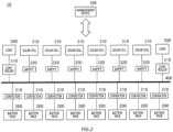
Fig. 2 schematically shows an example of thesystem 10. -
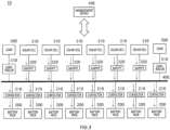
Fig. 3 schematically shows an example of a flow of a current in thesystem 10 at a time of charging. -
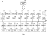
Fig. 4 schematically shows an example of a flow of a current of thesystem 10 at a time of discharging. -
Fig. 5 schematically shows an example of a functional configuration of themanagement device 100. -
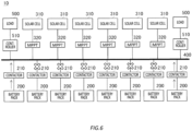
Fig. 6 schematically shows another example of a flow of a current of thesystem 10 at a time of discharging. -
Fig. 7 schematically shows an example ofairplane 600 to which thesystem 10 is mounted thereto. -
Fig. 8 schematically shows another example of theairplane 600 to which thesystem 10 is mounted thereto. -
Fig. 9 schematically shows another example of theairplane 600 to which thesystem 10 is mounted thereto. -
Fig. 10 schematically shows another example of theairplane 600 to which thesystem 10 is mounted thereto. -
Fig. 11 schematically shows an example of anHAPS 700 to which thesystem 10 is mounted thereto. -
Fig. 12 schematically shows an example of a hardware configuration of acomputer 1200 which functions as themanagement device 100. - A battery (in particular, a battery using a lithium metal negative end) has a characteristic that its deterioration is brought early if the discharge rate is low. As one of the solutions, a technology that increases the discharge rate per cell by alternately using cells in a pack is proposed. However, a component for switching is required for switching the cell in the pack, causing a weight increase and high cost of the pack. Also, the battery has a characteristic that the deterioration is brought early if the charge rate is high. The
system 10 according to the present embodiment realizes a charging and discharging management of the battery considering such characteristics of the battery. - Hereinafter, the present invention will be described through embodiments of the invention, but the following embodiments do not limit the invention according to claims. In addition, not all of the combinations of features described in the embodiments are essential to the solution of the invention.
-
Fig. 1 schematically shows an example of asystem 10. Thesystem 10 includes amanagement device 100. Themanagement device 100 manages a plurality of battery packs 200 which are connected to abus 400 in parallel to which a plurality ofpower generation units 300 and a plurality ofloads 500 are connected. Themanagement device 100 may manage charging and discharging of the plurality of battery packs 200. - The
system 10 may include the plurality of battery packs 200. Thesystem 10 may include the plurality ofpower generation units 300. Thesystem 10 may include the plurality ofloads 500. - A battery type of the
battery pack 200 may be any type. Thebattery pack 200 is a battery using lithium for a negative end, for example. Thebattery pack 200 is a lithium-ion battery, for example. Thebattery pack 200 may have a lithium metal battery. - The
battery pack 200 includes a plurality ofcells 202. Thecell 202 may be a battery cell using metallic lithium for a negative end, for example. - The
power generation unit 300 performs a solar power generation, for example. A power generation technique according to thepower generation unit 300 may be another power generation technique. Thebattery pack 200 can be charged by power generated by thepower generation unit 300. The plurality ofpower generation units 300 may be connected to thebus 400 in parallel. - The
load 500 consumes the power of thebattery pack 200 or consumes the power generated by thepower generation unit 300. Theload 500 may be any device that is operated by electric power. For example, when thesystem 10 is mounted in a flight vehicle, theload 500 may be a device related to a flight of a flight vehicle such as a propeller or an elevator. - The
management device 100 according to the present embodiment manages the charging and discharging of the plurality of battery packs 200 so that a deterioration of the plurality of battery packs 200 is suppressed. -
Fig. 2 schematically shows an example of thesystem 10. In an example shown inFig. 2 , each of the plurality of battery packs 200 is connected to thebus 400 via acontactor 210. Also, a plurality ofsolar cells 310 are connected to thebus 400 via an MPPT (Maximum Power Point Tracking) 320. Thesolar cell 310 may be an example of thepower generation unit 300. Also, a plurality ofloads 500 are connected to thebus 400 via acontroller 510. Here, aload 500 on the left side that is arranged on the left side of thebus 400, and aload 500 on the right side that is arranged on the right side of thebus 400 are illustrated. - When the battery packs 200 are separately described, from the left side to the right side, the battery packs may be described as a battery pack A, a battery pack B, a battery pack C, a battery pack D, a battery pack E, a battery pack F, a battery pack G, and a battery pack H. When the
contactors 210 are separately described, from the left side to the right side, the contactors may be described as a contactor A, a contactor B, a contactor C, a contactor D, a contactor E, a contactor F, a contactor G, and a contactor E. -
Fig. 3 schematically shows an example of a flow of a current in thesystem 10 at a time of charging. As shown in the example ofFig. 3 , themanagement device 100 may control the electrical connection of the plurality of battery packs 200 to thebus 400 so that the plurality of battery packs 200 are simultaneously charged by power generated by the plurality ofsolar cells 310. Themanagement device 100 controls the power to be simultaneously supplied for all of the battery packs 200 by opening all of thecontactors 210 when a power generation by the plurality ofsolar cells 310 is started, for example. -
Fig. 4 schematically shows an example of a flow of a current of thesystem 10 at a time of discharging. Themanagement device 100 may manage the plurality of battery packs 200 to have the plurality of battery packs 200 being alternately discharged so that the discharge rate of each of the plurality of battery packs 200 is higher compared to a case in which all of the plurality of battery packs 200 are discharged. - The
management device 100 controls a plurality ofcontactors 210 so that the plurality of battery packs 200 are sequentially discharged one by one, for example. Themanagement device 100 controls the plurality ofcontactors 210 so that the battery pack A, the battery pack B, the battery pack C, the battery pack D, the battery pack E, the battery pack F, the battery pack G, and the battery pack H are repeatedly discharged in the above order, for example. Also, themanagement device 100 controls the plurality ofcontactors 210 so that abattery pack 200 with a higher voltage is sequentially discharged with a higher priority, among the plurality of battery packs 200, for example. In this manner, by causing eightbattery packs 200 to be alternately discharged, the discharge rate of thebattery pack 200 can be eight times compared to a case in which all of the eightbattery packs 200 are discharged. - Although the
management device 100 accordingly switches the charge and the discharge for the plurality of battery packs 200, when all of the plurality ofcontactors 210 are opened for the charge, if a voltage difference between abattery pack 200 with a highest voltage and abattery pack 200 with a lowest voltage among the plurality of battery packs 200 is large, for example, the charge rate of the latter one may be accelerated due to a current flowing from the former one to the latter one, causing the deterioration of the latter one to be accelerated. - The
management device 100 according to the present embodiment manages the plurality of battery packs 200 to have the plurality of battery packs 200 being alternately discharged so that a voltage difference between abattery pack 200 with a highest voltage and abattery pack 200 with a lowest voltage among the plurality of battery packs 200 is not greater than a predetermined voltage threshold. In other words, themanagement device 100 manages plurality of battery packs 200 to have the plurality of battery packs 200 being alternately discharged so that a remaining capacity difference between abattery pack 200 whose remaining capacity is maximum and abattery pack 200 whose remaining capacity is minimum among the plurality of battery packs 200 is not greater than a predetermined remaining capacity threshold. - For example, the
management device 100 first starts discharging of thebattery pack 200 with a highest voltage (may be described as a first battery pack 200) among the plurality of battery packs 200. Themanagement device 100 starts discharging of thesecond battery pack 200 before a difference between the voltage of thefirst battery pack 200 and abattery pack 200 with a highest voltage among another plurality of battery packs 200 (may be described as a second battery pack 200) among the plurality of battery packs 200 becomes greater than a voltage threshold. Themanagement device 100 stops the discharging of thefirst battery pack 200 after a predetermined amount of time has elapsed from the start of the discharging of thesecond battery pack 200. By repeating such a control, the voltage difference between thebattery pack 200 with a highest voltage and thebattery pack 200 with a lowest voltage among the plurality of battery packs 200 can be caused not to be greater than a predetermined voltage threshold. Note that the predetermined amount of time may be around 0.01- 1 second, for example. By causing the discharging of thefirst battery pack 200 to be stopped after a predetermined amount of time has elapsed from the start of the discharging of thesecond battery pack 200, the discharge can be done with no interruption. -
Fig. 5 schematically shows an example of a functional configuration of themanagement device 100. Themanagement device 100 may include amanagement unit 110, a pack-relatedinformation acquiring unit 112, and anestimation unit 114. - The
management unit 110 manages the plurality of battery packs 200 to have the plurality of battery packs 200 being alternately discharged so that a voltage difference between abattery pack 200 with a highest voltage and abattery pack 200 with a lowest voltage among the plurality of battery packs 200 is not greater than a predetermined voltage threshold. - For example, the
management unit 110 first starts discharging of thebattery pack 200 with a highest voltage (may be described as a first battery pack 200) among the plurality of battery packs 200. Then, themanagement unit 110 starts discharging of thesecond battery pack 200 before a difference between the voltage of thefirst battery pack 200 and abattery pack 200 with a highest voltage among another plurality of battery packs 200 (may be described as a second battery pack 200) among the plurality of battery packs 200 becomes greater than a predetermined voltage threshold. Furthermore, themanagement unit 110 stops the discharging of thefirst battery pack 200 after a predetermined amount of time has elapsed from the start of the discharging of thesecond battery pack 200. Themanagement unit 110 causes the plurality of battery packs 200 to be sequentially discharged by repeating such a control. - The
management unit 110 may control the electrical connection of the plurality of battery packs 200 to thebus 400 so that the plurality of battery packs 200 are simultaneously charged by power generated by the plurality ofsolar cells 310. For example, themanagement unit 110 opens all of the plurality ofcontactors 210 so that the plurality of battery packs 200 are simultaneously charged by the power generated by the plurality ofsolar cells 310. - When the plurality of battery packs 200 are charged by the power generated by the plurality of
solar cells 310, themanagement unit 110 may manage voltage from thesolar cell 310 to thebus 400 to fall within a range between voltage of thebattery pack 200 with a highest voltage and voltage of thebattery pack 200 with a lowest voltage among the plurality of battery packs 200. Themanagement unit 110 may manage, by controlling a plurality ofMPPTs 320, the voltage from thesolar cell 310 to thebus 400 to fall within a range between voltage of thebattery pack 200 with a highest voltage and voltage of thebattery pack 200 with a lowest voltage among the plurality of battery packs 200. - The pack-related
information acquiring unit 112 acquires pack-related information related to thebattery pack 200 for each of the plurality of battery packs 200. For example, the pack-relatedinformation acquiring unit 112 acquires information detected by a sensor that is arranged for each of the plurality of battery packs 200, as pack-related information, from the sensor. - The pack-related information may include an OCV (Open Circuit Voltage) of the
battery pack 200. The pack-related information may include a CCV (Closed Circuit Voltage) of thebattery pack 200. The pack-related information may include a DCIR (Direct Current Internal Resistence) of thebattery pack 200. The pack-related information may include an SOH (State of Health) of thebattery pack 200. The pack-related information may include an SOC (State Of Charge) of thebattery pack 200. The pack-related information may include a current value of thebattery pack 200. The pack-related information may include a discharge duration of thebattery pack 200. The pack-related information may include an integrated capacity of thebattery pack 200. The pack-related information may include a temperature of thebattery pack 200. - The
estimation unit 114 estimates a state of thebattery pack 200 based on the pack-related information acquired by the pack-relatedinformation acquiring unit 112. Theestimation unit 114 may perform estimation by using an estimation method that is used in the existing BMS (Battery Management System). - For example, the
estimation unit 114 stores a relationship between the SOC and the DCIR of thebattery pack 200 to estimate the OCV of thebattery pack 200 based on the DCIR, the SOH, the current value, the discharge duration, the CCV, and the integrated capacity that are stored. - Furthermore, for example, the
estimation unit 114 first estimates an SOC and an SOH before starting the discharge based on an OCV, a current value, a discharge duration, a CCV, an integrated capacity, and the temperature before starting the discharge. Then, theestimation unit 114 uses the data to estimate a current DCIR based on the database that is previously stored. Furthermore, theestimation unit 114 estimates a current OCV based on the current DCIR, the CCV, and the current value that are estimated. - The
management unit 110 may manage, based on the OCV of each of the plurality of battery packs 200 that is acquired by the pack-relatedinformation acquiring unit 112, the plurality of battery packs 200 to have the plurality of battery packs 200 to be alternately discharged so that a voltage difference between abattery pack 200 with a highest voltage and abattery pack 200 with a lowest voltage among the plurality of battery packs 200 is not greater than a predetermined voltage threshold. - Furthermore, he
management unit 110 may manage, based on the OCV of each of the plurality of battery packs 200 that is estimated by theestimation unit 114, the plurality of battery packs 200 to have the plurality of battery packs 200 to be alternately discharged so that a voltage difference between abattery pack 200 with a highest voltage and abattery pack 200 with a lowest voltage among the plurality of battery packs 200 is not greater than a predetermined voltage threshold. - The
management unit 110 may preset a voltage threshold so that a charge rate from thebattery pack 200 with a highest voltage to thebattery pack 200 with a lowest voltage is not faster than a predetermined charge rate threshold. The charge rate threshold may be 0.3C or less, or more desirably, may be 0.2C or less, for example. - For example, when a
battery pack 200 with a DICR of 1.87Ω minimum, 1.99Ω average, and 270 - 396V of voltage is used with 5 kWh (15 Ah), for setting the DCIR to 2Ω and the charge rate threshold to be 0.2C of 3A by charging, a voltage difference between thebattery pack 200 with a highest voltage and thebattery pack 200 with a lowest voltage < (0.2 (C) ×15 (Ah) × 2 (Ω) = 6V), and the voltage threshold is 6V. In this case, themanagement unit 110 starts the discharge of abattery pack 200 with a highest voltage (described as a first battery pack 200), then starts the discharge of asecond battery pack 200 and then stops the discharge of thefirst battery pack 200 after a predetermined amount of time has elapsed before the voltage of thefirst battery pack 200 decreases to be lower than the voltage of abattery pack 200 whose voltage is the second highest (described as the second battery pack 200) by 6V or more. - Also, for setting to 0.3C, the voltage difference between the
battery pack 200 with a highest voltage and thebattery pack 200 with a lowest voltage < (0.3 (C) ×15 (Ah) ×2 (Ω) = 9V), and the voltage threshold is 9V. In this case, themanagement unit 110 starts the discharge of thefirst battery pack 200, then starts the discharge of asecond battery pack 200 and then stops the discharge of thefirst battery pack 200 after a predetermined amount of time has elapsed, before the voltage of thefirst battery pack 200 decreases to be lower than the voltage of thesecond battery pack 200 by 9V or more. - When an excess power generation amount exists due to a power generation amount increased by the
solar cell 310, for example, themanagement unit 110 may manage thesolar cell 310 to consume the generated power so that a charge rate at which the plurality of battery packs 200 are charged is not faster than the charge rate threshold. For example, themanagement unit 110 controls thecontroller 510 to cause theload 500 to consume the power generated by thesolar cell 310 so that a charge rate at which the plurality of battery packs 200 is charged by the power generated by thesolar cell 310 is not faster than the charge rate threshold. - When a discharge rate of the
battery pack 200 that is discharging among the plurality of battery packs 200 continues to be slower than a predetermined discharge rate threshold for a predetermined amount of time, themanagement unit 110 may manage a power consumption of abattery pack 200 that is discharging to be increased. For example, themanagement unit 110 controls thecontroller 510 to cause theload 500 to consume the power of thebattery pack 200. The predetermined amount of time may be arbitrarily set by seconds or minutes. In this way, early deterioration of thebattery pack 200 due to the low discharge rate continuing for a long time can be prevented. The discharge rate threshold may be 0.3C - 2.0C, or more desirably, may be 0.4C - 1.0C. - The following table 1 shows an experimental result obtained by experimenting a deterioration degree for each of various discharge rates and charge rates of the
battery pack 200 that has a battery cell using metallic lithium for a negative end. The experiment is performed multiple times for each combination of the discharge rate and the charge rate, in which a case where 80% of an initial capacity is maintained for an average of 250 cycles or more is "©", a case where 80% of the initial capacity is maintained for an average of 200 cycles or more and less than 250 cycles is "O", and a case where an average of 180 cycles or less is "×". The experiment result shows that, as a result of repeating discharging at a discharge rate of 0.3C and charging at a charge rate of 0.1C for each of the plurality of battery packs 200, 80% of the initial capacity is maintained for an average of 200 cycles or more and less than 250 cycles, for example. Also, the experiment result shows that, as a result of repeating discharging at a discharge rate of 0.5C and charging at a charge rate of 0.2C for each of the plurality of battery packs 200, 80% of the initial capacity is maintained, so the average was 250 cycles or more, for example.(Table 1) DISCHARGE RATE 0.05 0.1 0.2 0.8 0.4 0.5 0.7 1 2 3 CHARGE RATE 0.05 × × × ○ ⊚ ⊚ ⊚ ⊚ ○ × 0.1 × × × ○ ⊚ ⊚ ⊚ ⊚ ○ × 0.2 × × × ○ ○ ⊚ ⊚ ⊚ ○ × 0.3 × × × × ○ ○ ⊚ ⊚ × × 0.4 × × × × × × × × × × 0.5 × × × × × × × × × × 0.7 × × × × × × × × × × 1 × × × × × × × × × × - As shown in table 1, the discharge rate is desirably 0.3C - 2.0C, and more desirably, 0.4C - 1.0C. The charge rate is desirably 0.3C or less, and more desirably 0.2C or less.
-
Fig. 6 schematically shows another example of a flow of a current of thesystem 10 at a time of discharging. Themanagement unit 110 may manage the plurality of battery packs 200 to be sequentially discharged as a set of two or more. For example, themanagement unit 110 manages the plurality of battery packs 200 to be sequentially discharged two by two. Also, for example, themanagement unit 110 manages the plurality of battery packs 200 to be sequentially discharged three by three. Also, for example, themanagement unit 110 manages the plurality of sound battery packs 200 to be sequentially discharged four by four. These are examples, and themanagement unit 110 may manage the plurality of battery packs 200 to be sequentially discharged by a larger number than described above. -
Fig. 6 illustrates a case where the plurality of battery packs 200 includes four left side battery packs and four right side battery packs arranged in a horizontally symmetrical manner and themanagement unit 110 manages the plurality of battery packs 200 so that each of the plurality of battery packs on theleft side 200 and the plurality of battery packs on theright side 200 is sequentially discharged one by one in a horizontally symmetrical manner. Themanagement unit 110 may control the plurality ofcontactors 210 so that each of the plurality of battery packs on theleft side 200 and the plurality of battery packs on theright side 200 is sequentially discharged one by one in a horizontally symmetrical manner. - For example, the
management unit 110 controls the plurality ofcontactors 210 so that the plurality of battery packs are sequentially discharged in the following order: thefirst battery pack 200 and theeighth battery pack 200; thesecond battery pack 200 and theseventh battery pack 200; thethird battery pack 200 and thesixth battery pack 200; and thefourth battery pack 200 and thefifth battery pack 200. For example, when thefirst battery pack 200 and thesecond battery pack 200 are caused to perform the discharge, the length of a power transmission path to theload 500 on the left side decreases, but a power transmission path to theload 500 on the right side increases, leading to poor power transmission efficiency. On the contrary, the horizontally symmetrical discharge can prevent the length of the power transmission path for one of theload 500 on the left side and theload 500 on the right side from increasing, and can suppress decline in the power transmission efficiency. Note that in this case, when thefirst battery pack 200 and theeighth battery pack 200 are discharged, themanagement unit 110 may cause thefirst battery pack 200 and theeighth battery pack 200 to be simultaneously discharged, alternately discharged, or sequentially discharged. - The
management unit 110 may manage a pair of thefirst battery pack 200 and theeighth battery pack 200, a pair of thesecond battery pack 200 and theseventh battery pack 200, a pair of thethird battery pack 200 and thesixth battery pack 200, and a pair of thefourth battery pack 200 and thefifth battery pack 200 to be preferentially discharged from a pair with a higher voltage. For example, themanagement unit 110 specifies abattery pack 200 with a higher voltage for each of the plurality of pairs, and causes the specified pair of thebattery pack 200 with higher voltage to be preferentially discharged. Also, for example, themanagement unit 110 causes the pair with higher voltage in average among the plurality of pairs to be preferentially discharged. - The
management unit 110 specifies, for example, abattery pack 200 with a higher voltage for each of the plurality of pairs, and determines the order of the pairs sequentially from the highest voltage. Furthermore, themanagement unit 110 causes the plurality of pairs to be discharged while switching the pairs appropriately according to the determined order so that a voltage difference between thebattery pack 200 with a highest voltage and thebattery pack 200 with a lowest voltage among the plurality of battery packs 200 is not greater than a voltage threshold. - Also, the
management unit 110 may manage the plurality of battery packs 200 to be sequentially discharged for each combination formed of any battery pack from each of the plurality of battery packs on theleft side 200 and the plurality of battery packs on theright side 200. For example, themanagement unit 110 manages the plurality of battery packs 200 so as to be sequentially discharged for each combination, the combination includes a combination of thefirst battery pack 200 with any of thefifth battery pack 200 to theeighth battery pack 200, a combination of thesecond battery pack 200 with any of the remaining three of thefifth battery pack 200 to theeighth battery pack 200, a combination of thethird battery pack 200 with any of the remaining two of thefifth battery pack 200 to theeighth battery pack 200, and a combination of thefourth battery pack 200 with the remainingbattery pack 200 among thefifth battery pack 200 to theeighth battery pack 200. -
Fig. 7 schematically shows an example ofairplane 600 to which thesystem 10 is mounted thereto. Theairplane 600 may be an example of a flight vehicle. InFig. 7 , abattery pack 220 to abattery pack 231 are illustrated as an example of the plurality of battery packs 200. In the example shown inFig. 7 , thebattery pack 220 to thebattery pack 224 are arranged in a left-wing portion 622 of awing portion 620, thebattery pack 225 and thebattery pack 226 are arranged in anaircraft body 610, and thebattery pack 227 to thebattery pack 231 are arranged in a right-wing portion 624 of awing portion 620. - In
Fig. 7 , an illustration of a wiring from themanagement device 100, the plurality ofcontactors 210, the plurality ofpower generation units 300, and thebattery pack 220 to thebus 400 of thebattery pack 231 is omitted. Themanagement device 100 is arranged in theaircraft body 610 of theairplane 600, for example. Thepower generation unit 300 is arranged on an upper surface of thewing portion 620, for example. Thebattery pack 220 to thebattery pack 231 are connected to thebus 400 in parallel. Apropeller 630 is an example of theload 500. - Here, an order when the
management unit 110 causes the plurality of battery packs 200 to be sequentially discharged two by two is described. Themanagement unit 110 may repeat an order of selecting one by one from each of agroup 901 and agroup 905 arranged in a horizontally symmetrical manner to cause them to be discharged, selecting one by one from each of agroup 902 and agroup 904 to cause them to be discharged, and selecting two from agroup 903 to cause them to be discharged. The order of selecting one by one from each of two groups arranged in a horizontally symmetrical manner may be selected to match the front-back direction or selected with no matching of the front-back direction. For example, in the former case, themanagement unit 110 causes thebattery pack 220 and thebattery pack 229, thebattery pack 221 and thebattery pack 230, and thebattery pack 222 and thebattery pack 231 to be sequentially discharged, causes thebattery pack 223 and thebattery pack 227, and thebattery pack 224 and thebattery pack 228 to be sequentially discharged, and then causes thebattery pack 225 and thebattery pack 226 to be discharged. -
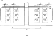
Fig. 8 schematically shows another example of theairplane 600 to which thesystem 10 is mounted thereto. Here, differences fromFig. 7 will be mainly described. In the example shown inFig. 8 , thebattery pack 220 to thebattery pack 225 are arranged in a left-wing portion 622 of awing portion 620, and thebattery pack 226 to thebattery pack 231 are arranged in a right-wing portion 624 of awing portion 620. - The
management unit 110 may repeat an order of selecting one by one from each of agroup 901 and agroup 904 arranged in a horizontally symmetrical manner to cause them to be discharged, and selecting one by one from each of agroup 902 and agroup 903 to cause them to be discharged. The order of selecting one by one from each of two groups arranged in a horizontally symmetrical manner may be selected to match the front-back direction or selected with no matching of the front-back direction. For example, in the former case, themanagement unit 110 causes thebattery pack 220 and thebattery pack 229, thebattery pack 221 and thebattery pack 230, and thebattery pack 222 and thebattery pack 231 to be sequentially discharged, causes thebattery pack 223 and thebattery pack 226, thebattery pack 224 and thebattery pack 227, and thebattery pack 225 and thebattery pack 228 to be sequentially discharged. -
Fig. 9 schematically shows another example of theairplane 600 to which thesystem 10 is mounted thereto. Here, differences fromFig. 7 will be mainly described. In the example shown inFig. 9 , thebattery pack 220 to thebattery pack 226 are arranged on the left side of theairplane 600, thebattery pack 227 to 240 are arranged at the center portion of theairplane 600, and thebattery pack 231 to thebattery pack 237 are arranged on the right side of theairplane 600. - The
management unit 110 may repeat an order of selecting one by one from each of agroup 901 and agroup 905 arranged in a horizontally symmetrical manner to cause them to be discharged, selecting one by one from each of agroup 902 and agroup 904 to cause them to be discharged, and selecting two by two from agroup 903 to cause them to be discharged. The order of selecting one by one from each of two groups arranged in a horizontally symmetrical manner may be selected to match the front-back direction or selected with no matching of the front-back direction. For example, in the former case, themanagement unit 110 causesbattery pack 220 and thebattery pack 236, thebattery pack 221 and thebattery pack 237 to be sequentially discharged, causes thebattery pack 222 and thebattery pack 231, thebattery pack 223 and thebattery pack 232, thebattery pack 224 and thebattery pack 233, thebattery pack 225 and thebattery pack 234, and thebattery pack 226 and thebattery pack 235 to be sequentially discharged, and causes thebattery pack 227 and thebattery pack 228, and thebattery pack 229 and thebattery pack 230 to be sequentially discharged. -
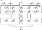
Fig. 10 schematically shows another example of theairplane 600 to which thesystem 10 is mounted thereto. Here, differences fromFig. 7 will be mainly described. In the example shown inFig. 10 , thebattery pack 220 to thebattery pack 223, thebattery pack 228 and thebattery pack 229 are arranged in the left-wing portion 622 of thewing portion 620, thebattery pack 224 to thebattery pack 227 are arranged at the center portion of theairplane 600, and thebattery pack 230 to thebattery pack 235 are arranged in the right-wing portion 624 of thewing portion 620. - The
management unit 110 may repeat an order of selecting one by one from each of agroup 901 and agroup 905 arranged in a horizontally symmetrical manner to cause them to be discharged, selecting one by one from each of agroup 902 and agroup 904 to cause them to be discharged, and selecting two by two from agroup 903 to cause them to be discharged. The order of selecting one by one from each of two groups arranged in a horizontally symmetrical manner may be selected to match the front-back direction or selected with no matching of the front-back direction. For example, in the former case, themanagement unit 110 causesbattery pack 220 and thebattery pack 234, thebattery pack 221 and thebattery pack 235 to be sequentially discharged, causes thebattery pack 222 and thebattery pack 232, thebattery pack 223 and thebattery pack 233 to be sequentially discharged, thebattery pack 229 and thebattery pack 231, thebattery pack 228 and thebattery pack 230, thebattery pack 226 and thebattery pack 227, and thebattery pack 224 and thebattery pack 225 to be sequentially discharged. -
Fig. 11 schematically shows an example of anHAPS 700 to which thesystem 10 is mounted thereto. TheHAPS 700 is a flight vehicle that provides a wireless communication service to auser terminal 30 in acommunication area 704 that is formed by irradiating abeam 702 to the ground. - The
HAPS 700 includes anaircraft body 710, acentral part 720, apropeller 730, apod 740, and asolar panel 750. Theaircraft body 710 has awing portion 712. Thewing portion 712 includes a left-wing portion 714 and a right-wing portion 716. - Inside the
wing portion 712, a plurality of battery packs 200 which are connected in parallel are arranged. Among the plurality of battery packs 200, a plurality of battery packs 200 on the left side may be arranged in the left-wing portion 714, and a plurality of battery packs 200 on the right side may be arranged in the right-wing portion 716. The plurality of battery packs 200 may be connected to abus 400 via a plurality ofcontactors 210. Thesolar panel 750 may be connected to thebus 400 via anMPPT 320. The power discharged by the plurality of battery packs 200 is utilized by each component included in theHAPS 700. For example, the power discharged by the plurality of battery packs 200 is utilized by a motor of thepropeller 730. The motor of thepropeller 730 may be an example of theload 500. - Inside the
central part 720, aflight control unit 722, acommunication controlling unit 724, and amanagement device 100 that is not shown are arranged. Theflight control unit 722 controls the flight of theHAPS 700 by using the power discharged by the plurality of battery packs 200. Thecommunication controlling unit 724 controls the communication of theHAPS 700 by using the power discharged by the plurality of battery packs 200. - The
flight control unit 722 controls the flight of theHAPS 700 by controlling the rotation of thepropeller 730, for example. Also, theflight control unit 722 may control the flight of theHAPS 700 by changing the angle of a flap or an elevator that are not shown. Theflight control unit 722 may include various types of sensors such as a positioning sensor such as a GPS sensor, a gyro sensor, and an acceleration sensor to manage a position, a movement direction, and a movement speed of theHAPS 700. - The
communication controlling unit 724 forms thecommunication area 704 on the ground by using an SL (Service Link) antenna. Thecommunication controlling unit 724 forms a service link between theuser terminal 30 on the ground by using the SL antenna. The SL antenna may be a multi-beam antenna. Thecommunication area 704 may be a multi-cell. - The
communication controlling unit 724 may form a feeder link between agateway 40 on the ground by using an FL (Feeder Link) antenna. Thecommunication controlling unit 724 may access anetwork 20 via thegateway 40. - The
communication controlling unit 724 may communicate with acommunication satellite 50 by using a satellite communication antenna. Thecommunication controlling unit 724 may access thenetwork 20 via thecommunication satellite 50 and asatellite communication station 60. - The
user terminal 30 may be any communication terminal as long as it can communicate with theHAPS 700. For example, theuser terminal 30 is a mobile phone such as a smartphone. Theuser terminal 30 may be a tablet terminal, a PC (Personal Computer), and the like. Theuser terminal 30 may also be a so-called loT (Internet of Thing) device. Theuser terminal 30 may include anything that corresponds to a so-called IoE (Internet of Everything). - The
HAPS 700 relays a communication between thenetwork 20 and theuser terminal 30, for example, via the feeder link or thecommunication satellite 50, and the service link. TheHAPS 700 may provide a wireless communication service to theuser terminal 30 by relaying the communication between theuser terminal 30 and thenetwork 20. - The
network 20 includes a mobile communication network. The mobile communication network may conform to any of the 3G (3rd Generation) communication system, the LTE (Long Term Evolution) communication system, the 5G (5th Generation) communication system, and the 6G (6th Generation) communication system and the communication system of the subsequent generation. Thenetwork 20 may include the Internet. - For example, the
HAPS 700 transmits data received from theuser terminal 30 in thecommunication area 704 to thenetwork 20. In addition, for example, when theHAPS 700 receives data addressed to theuser terminal 30 in thecommunication area 704, via thenetwork 20, theHAPS 700 transmits the data to theuser terminal 30. - The
HAPS 700 maintains thecommunication area 704 in a specific area on the ground while circulating a predetermined flight path in the stratosphere, for example. TheHAPS 700 maintains the flight in the stratosphere by storing power generated by thesolar panel 750 in the daytime in the plurality of battery packs 200, and using the power of the plurality of battery packs 200 in the evening. TheHAPS 700 maintains the flight in the stratosphere by raising itself and storing potential energy while charging the plurality of battery packs 200 in the daytime and operating thepropeller 730 or the like by appropriately using the power in thebattery pack 200 while gradually descending in the evening, for example. - The
management device 800 manages a plurality of theHAPS 700. Themanagement device 800 may communicate with theHAPS 700 via thenetwork 20 and thegateway 40. Themanagement device 800 may communicate with theHAPS 700 via thenetwork 20, thesatellite communication station 60, and thecommunication satellite 50. - The
management device 800 controls theHAPS 700 by transmitting an instruction. Themanagement device 800 may cause theHAPS 700 to circle over a target area such that the target area on the ground is covered by thecommunication area 704. For example, theHAPS 700 maintains the feeder link with thegateway 40 by adjusting a pointing direction of the FL antenna while flying in a circular orbit over the target area, and maintains the coverage of the target area by thecommunication area 704 by adjusting a pointing direction of the SL antenna. - The
management unit 110 of themanagement device 100 manages, as described above, plurality of battery packs 200 to have the plurality of battery packs 200 being alternately discharged so that a voltage difference between abattery pack 200 with a highest voltage and abattery pack 200 with a lowest voltage among the plurality of battery packs 200 is not greater than a voltage threshold. In this way, as described above, the deterioration of the plurality of battery packs 200 can be reduced, and a period of time in which theHAPS 700 can maintain its flight in the stratosphere can be extended. - The
management unit 110 may manage theHAPS 700 to be raised by the power generated by thesolar panel 750 so that a charge rate at which the plurality of battery packs 200 are charged by the power generated by thesolar panel 750 is not faster than a charge rate threshold. For example, themanagement unit 110 controls the power generated by thesolar panel 750 to be supplied to thepropeller 730, the flap and the elevator or the like, and theflight control unit 722 controls thepropeller 730, the flap and the elevator so that theHAPS 700 is raised. By converting surplus power into potential energy, the surplus power can be utilized with no waste. - When a discharge rate of the
battery pack 200 that is managed to be discharged among the plurality of battery packs 200 continues to be slower than a discharge rate threshold for a predetermined amount of time, themanagement unit 110 may manage theload 500 to be raised by the power of abattery pack 200 which is managed to be discharged. For example, themanagement unit 110 controls the power of thebattery pack 200, which is managed to be discharged, to be supplied to thepropeller 730, the flap and the elevator or the like, and theflight control unit 722 controls thepropeller 730, the flap and the elevator so that theHAPS 700 is raised. By converting the power into one energy while setting the discharge rate of thebattery pack 200 which is managed to be discharged to a preferred discharge rate, the power can be utilized with no waste. - The
management unit 110 may manage the plurality of battery packs 200 to have the plurality of battery packs 200 being alternately discharged so that a voltage difference between abattery pack 200 with a highest voltage and abattery pack 200 with a lowest voltage is not greater than a first voltage threshold during a time slot defined as daytime, and to have the plurality of battery packs 200 being alternately discharged so that a voltage difference between thebattery pack 200 with a highest voltage and thebattery pack 200 with a lowest voltage is not greater than a second voltage threshold that is greater than the first voltage threshold during a time slot defined as evening. The plurality of battery packs 200 are not charged by thesolar panel 750 in the evening, so there is few problem even if the voltage difference between thebattery pack 200 with a highest voltage and thebattery pack 200 with a lowest voltage is greater than that of the daytime. By setting the voltage threshold used in the evening to the second voltage threshold greater than the first voltage threshold used in the daytime, the number of times of switching thebattery pack 200 that is managed to be discharged can be reduced. -
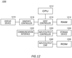
Fig. 12 schematically shows an example of a hardware configuration of acomputer 1200 which functions as themanagement device 100. Programs installed in thecomputer 1200 can cause thecomputer 1200 to function as one or more "units" of the device according to the present embodiment or can cause thecomputer 1200 to execute operations associated with the devices according to the present embodiment or the one or more "units", and/or can cause thecomputer 1200 to execute a process according to the present embodiment or steps of the process. Such a program may be executed by aCPU 1212 to cause thecomputer 1200 to perform particular operations associated with some or all of the blocks in the flowcharts and block diagrams described in the specification. - The
computer 1200 according to the present embodiment includes theCPU 1212, aRAM 1214, and agraphics controller 1216, which are connected to each other via ahost controller 1210. Also, thecomputer 1200 includes input/output units such as acommunication interface 1222, astorage device 1224, a DVD drive and an IC card drive, which are connected to thehost controller 1210 via an input/output controller 1220. Thestorage device 1224 may be a hard disk drive, a solid-state drive, and the like. Thecomputer 1200 also includes aROM 1230 and a legacy input/output unit such as a keyboard, which are connected to the input/output controller 1220 via an input/output chip 1240. - The
CPU 1212 operates according to the programs stored in theROM 1230 and theRAM 1214, thereby controlling each unit. Thegraphics controller 1216 obtains image data which is generated by theCPU 1212 in a frame buffer or the like provided in theRAM 1214 or in itself so as to cause the image data to be displayed on adisplay device 1218. - The
communication interface 1222 communicates with other electronic devices via a network. Thestorage device 1224 stores a program and data used by theCPU 1212 in thecomputer 1200. The IC card drive reads the program and data from an IC card, and/or writes the program and data to the IC card. - The
ROM 1230 stores therein a boot program or the like executed by thecomputer 1200 at the time of activation, and/or a program depending on the hardware of thecomputer 1200. The input/output chip 1240 may also connect various input/output units via a USB port, a parallel port, a serial port, a keyboard port, a mouse port, or the like to the input/output controller 1220. - A program is provided by a computer-readable storage medium such as the DVD-ROM or the IC card. The program is read from the computer-readable storage medium, installed into the
storage device 1224,RAM 1214, orROM 1230, which are also examples of a computer-readable storage medium, and executed by theCPU 1212. Information processing written in these programs is read by thecomputer 1200, and provides cooperation between the programs and the various types of hardware resources described above. An apparatus or method may be constituted by realizing the operation or processing of information in accordance with the usage of thecomputer 1200. - For example, in a case where a communication is performed between the
computer 1200 and an external device, theCPU 1212 may execute a communication program loaded in theRAM 1214 and instruct thecommunication interface 1222 to perform communication processing based on a process written in the communication program. Thecommunication interface 1222, under control of theCPU 1212, reads transmission data stored on a transmission buffer region provided in a recording medium such as theRAM 1214, thestorage device 1224, the DVD-ROM, or the IC card, and transmits the read transmission data to a network or writes reception data received from a network to a reception buffer region or the like provided on the recording medium. - In addition, the
CPU 1212 may cause all or a necessary portion of a file or a database to be read into theRAM 1214, the file or the database having been stored in an external recording medium such as thestorage device 1224, the DVD drive (DVD-ROM), the IC card, etc., and perform various types of processing on the data on theRAM 1214. Then, theCPU 1212 may write the processed data back in the external recording medium. - Various types of information, such as various types of programs, data, tables, and databases, may be stored in the recording medium to undergo information processing. The
CPU 1212 may execute, on the data read from theRAM 1214, various types of processing including various types of operations, information processing, conditional judgement, conditional branching, unconditional branching, information retrieval/replacement, or the like described throughout the present disclosure and specified by instruction sequences of the programs, to write the results back to theRAM 1214. In addition, theCPU 1212 may retrieve information in a file, a database, or the like in the recording medium. For example, when a plurality of entries, each having an attribute value of a first attribute associated with an attribute value of a second attribute, are stored in the recording medium, theCPU 1212 may search for an entry whose attribute value of the first attribute matches a designated condition, from among the plurality of entries, and read the attribute value of the second attribute stored in the entry, thereby obtaining the attribute value of the second attribute associated with the first attribute satisfying a predetermined condition. - The program or software module described above may be stored on the
computer 1200 or in a computer-readable storage medium near thecomputer 1200. In addition, a recording medium such as a hard disk or a RAM provided in a server system connected to a dedicated communication network or the Internet can be used as the computer-readable storage medium, thereby providing the program to thecomputer 1200 via the network. - Blocks in flowcharts and block diagrams in the present embodiments may represent steps of processes in which operations are performed or "units" of apparatuses responsible for performing operations. A specific step and "unit" may be implemented by dedicated circuitry, programmable circuitry supplied along with a computer-readable instruction stored on a computer-readable storage medium, and/or a processor supplied along with the computer-readable instruction stored on the computer-readable storage medium. The dedicated circuitry may include a digital and/or analog hardware circuit, or may include an integrated circuit (IC) and/or a discrete circuit. The programmable circuitry may include, for example, a reconfigurable hardware circuit including logical AND, logical OR, logical XOR, logical NAND, logical NOR, and other logical operations, and a flip-flop, a register, and a memory element, such as a field-programmable gate array (FPGA) and a programmable logic array (PLA).
- The computer-readable storage medium may include any tangible device capable of storing an instruction performed by an appropriate device, so that the computer-readable storage medium having the instruction stored thereon constitutes a product including an instruction that may be performed in order to provide means for performing an operation specified by a flowchart or a block diagram. Examples of the computer-readable storage medium may include an electronic storage medium, a magnetic storage medium, an optical storage medium, an electromagnetic storage medium, a semiconductor storage medium, and the like. More specific examples of computer-readable storage medium may include a floppy disk, a diskette, a hard disk, a random access memory (RAM), a read-only memory (ROM), an erasable programmable read-only memory (EPROM or Flash memory), an electrically erasable programmable read-only memory (EEPROM), a static random access memory (SRAM), a compact disc read-only memory (CD-ROM), a digital versatile disk (DVD), a Blu-ray (registered trademark) disc, a memory stick, an integrated circuit card, etc.
- The computer-readable instruction may include an assembler instruction, an instruction-set-architecture (ISA) instruction, a machine instruction, a machine dependent instruction, a microcode, a firmware instruction, state-setting data, or either of source code or object code written in any combination of one or more programming languages including an object-oriented programming language such as Smalltalk (registered trademark), JAVA (registered trademark), and C++, and a conventional procedural programming language such as a "C" programming language or a similar programming language.
- The computer-readable instruction may be provided to a general purpose computer, a special purpose computer, or a processor or programmable circuitry of another programmable data processing apparatus locally or via a local area network (LAN), a wide area network (WAN) such as the Internet or the like in order that the general purpose computer, the special purpose computer, or the processor or the programmable circuitry of the other programmable data processing apparatus performs the computer-readable instruction to provide means for performing operations specified by the flowchart or the block diagram. Examples of the processor include a computer processor, a processing unit, a microprocessor, a digital signal processor, a controller, a microcontroller, and the like.
- While the present invention has been described by way of the embodiments, the technical scope of the present invention is not limited to the above-described embodiments. It is apparent to persons skilled in the art that various alterations or improvements can be made to the above-described embodiments. It is apparent from the description of the claims that embodiments added with such alterations or improvements can also be included in the technical scope of the present invention.
- It should be noted that the operations, procedures, steps, stages or the like of each process performed by an apparatus, system, program, and method shown in the scope of the claims, embodiments, or diagrams can be performed in any order as long as the order is not indicated by "prior to," "before," or the like and as long as the output from a previous process is not used in a later process. Even if the process flow is described by using phrases such as "first", "then" or the like in the scope of the claims, embodiments, or diagrams, it does not necessarily mean that the process must be performed in this order.
-
- 10 system
- 20 network
- 30 user terminal
- 40 gateway
- 50 communication satellite
- 60 satellite communication station
- 100 management device
- 110 management unit
- 112 pack-related information acquiring unit
- 114 estimation unit
- 200 battery pack
- 202 cell
- 210 contactor
- 220, 221, 222, 223, 224, 225, 226, 227, 228, 229, 230, 231, 232, 233, 234, 235, 236, 237 battery pack
- 300 power generation unit
- 310 solar cell
- 320 MPPT
- 400 bus
- 500 load
- 600 airplane
- 610 aircraft body
- 620 wing portion
- 622 left-wing portion
- 624 right-wing portion
- 630 propeller
- 700 HAPS
- 702 beam
- 704 communication area
- 710 aircraft body
- 712 wing portion
- 714 left-wing portion
- 716 right-wing portion
- 720 central part
- 722 flight control unit
- 724 communication controlling unit
- 730 propeller
- 740 pod
- 750 solar panel
- 800 management device
- 901, 902, 903, 904, 905 group
- 1200 computer
- 1210 host controller
- 1212 CPU
- 1214 RAM
- 1216 graphics controller
- 1218 display device
- 1220 input/output controller
- 1222 communication interface
- 1224 storage device
- 1230 ROM
- 1240 input/output chip.
Claims (25)
- A system comprising:
a management unit that manages a plurality of battery packs, which are connected in parallel to a bus to which a power generation unit and a load are connected, to have the plurality of battery packs being alternately discharged so that a voltage difference between a battery pack with a highest voltage and a battery pack with a lowest voltage among the plurality of battery packs is not greater than a voltage threshold. - The system according to claim 1, wherein each of the plurality of battery packs has a lithium metal battery.
- The system according to claim 1 or 2, wherein the management unit controls an electrical connection from the plurality of battery packs to the bus so that the plurality of battery packs are simultaneously charged by power generated by the power generation unit.
- The system according to claim 3, wherein when the plurality of battery packs are charged by the power generated by the power generation unit, the management unit manages voltage from the power generation unit to the bus to fall within a range between voltage of a battery pack with a highest voltage and voltage of a battery pack with a lowest voltage among the plurality of battery packs.
- The system according to claim 3 or 4, wherein the management unit manages the power generated by the power generation unit to be consumed so that a charge rate at which the plurality of battery packs are charged by the power generated by the power generation unit is not faster than a predetermined charge rate threshold.
- The system according to claim 5, wherein the charge rate threshold is 0.3C or less.
- The system according to claim 6, wherein the charge rate threshold is 0.2C or less.
- The system according to any one of claim 1 to 7, wherein the management unit manages a battery pack with a higher voltage among the plurality of battery packs to be preferentially discharged.
- The system according to any one of claim 1 to 8, wherein the management unit manages the plurality of battery packs to be sequentially discharged as a set of two or more.
- The system according to any one of claim 1 to 9, whereinthe plurality of battery packs include a plurality of battery packs on a left side and a plurality of battery packs on a right side arranged in a horizontally symmetrical manner, andthe management unit manages the plurality of battery packs so that at least one of the plurality of battery packs on the left side and at least one of the plurality of battery packs on the right side are sequentially discharged in a horizontally symmetrical manner.
- The system according to claim 10, wherein the load includes a left-side load arranged on the left side of the bus and a right-side load arranged on the right side of the bus.
- The system according to any one of claim 1 to 11, comprising:a pack-related information acquiring unit that acquires pack-related information related to the plurality of battery packs; andan estimation unit that estimates an open circuit voltage of the plurality of battery packs based on the pack-related information, whereinthe management unit manages the plurality of battery packs to have the plurality of battery packs being alternately discharged so that a difference in the open circuit voltage between a battery pack in which the open circuit voltage is highest and a battery pack in which the open circuit voltage is lowest is not greater than the voltage threshold.
- The system according to any one of claim 1 to 12, wherein the management unit manages the plurality of battery packs to start discharging of a first battery pack with a highest voltage among the plurality of battery packs, then starts discharging of a second battery pack and then stop the discharging of the first battery pack before a difference between the voltage of the first battery pack and voltage of the second battery pack with a highest voltage among another plurality of battery packs among the plurality of battery packs becomes greater than the voltage threshold.
- The system according to any one of claim 1 to 13, whereinthe system is mounted in a flight vehicle,the plurality of battery packs are arranged in a wing portion of the flight vehicle,the power generation unit performs a solar power generation, andthe load is a motor that rotates a propeller of the flight vehicle.
- The system according to claim 14, wherein the management unit manages the flight vehicle to be raised by the power generated by the power generation unit so that a charge rate at which the plurality of battery packs are charged by the power generated by the power generation unit is not faster than a predetermined charge rate threshold.
- The system according to claim 15, wherein the charge rate threshold is 0.3C or less.
- The system according to claim 16, wherein the charge rate threshold is 0.2C or less.
- The system according to any one of claim 14 to 17, wherein when a discharge rate of the battery pack that is managed to be discharged among the plurality of battery packs continues to be slower than a predetermined discharge rate threshold for a predetermined amount of time, the management unit manages the flight vehicle to be raised by power of a battery pack which is managed to be discharged.
- The system according to claim 18, wherein the discharge rate threshold is between 0.3C and 2.0C.
- The system according to claim 19, wherein the discharge rate threshold is between 0.4C and 1.0C.
- The system according to any one of claim 14 to 20, wherein the management unit manages the plurality of battery packs to have the plurality of battery packs being alternately discharged so that a voltage difference between a battery pack with the voltage that is highest and a battery pack with the voltage that is lowest is not greater than a first voltage threshold during a time slot defined as daytime, and have the plurality of battery packs being alternately discharged so that the voltage difference between the battery pack with the voltage that is highest and the battery pack with the voltage that is lowest is not greater than a second voltage threshold that is greater than the first voltage threshold during a time slot defined as evening.
- The system according to any one of claim 14 to 21, comprising the flight vehicle.
- The system according to claim 22, wherein the flight vehicle includes
a communication controlling unit that provides a wireless communication service to a user terminal in a communication area that is formed by irradiating a beam to a ground by using the power discharged by the plurality of battery packs. - A program that causes a computer to function as:
a management unit that manages a plurality of battery packs, which are connected in parallel to a bus to which a power generation unit and a load are connected, to have the plurality of battery packs being alternately discharged so that a voltage difference between a battery pack with a highest voltage and a battery pack with a lowest voltage among the plurality of battery packs is not greater than a voltage threshold. - A management method of a plurality of battery packs performed by a computer, the plurality of battery packs being connected in parallel to a bus to which a power generation unit and a load are connected, the method comprises:
managing the plurality of battery packs to have the plurality of battery packs being alternately discharged so that a voltage difference between a battery pack with a highest voltage and a battery pack with a lowest voltage among the plurality of battery packs is not greater than a voltage threshold.
Applications Claiming Priority (2)
| Application Number | Priority Date | Filing Date | Title |
|---|---|---|---|
| JP2021145457A JP7320027B2 (en) | 2021-09-07 | 2021-09-07 | Systems, programs and management methods |
| PCT/JP2022/033195 WO2023037991A1 (en) | 2021-09-07 | 2022-09-02 | System, program, and management method |
Publications (4)
| Publication Number | Publication Date |
|---|---|
| EP4395118A1 true EP4395118A1 (en) | 2024-07-03 |
| EP4395118A4 EP4395118A4 (en) | 2025-01-22 |
| EP4395118C0 EP4395118C0 (en) | 2026-01-21 |
| EP4395118B1 EP4395118B1 (en) | 2026-01-21 |
Family
ID=85507594
Family Applications (1)
| Application Number | Title | Priority Date | Filing Date |
|---|---|---|---|
| EP22867313.3A Active EP4395118B1 (en) | 2021-09-07 | 2022-09-02 | System, program, and management method |
Country Status (5)
| Country | Link |
|---|---|
| US (1) | US12567608B2 (en) |
| EP (1) | EP4395118B1 (en) |
| JP (2) | JP7320027B2 (en) |
| CN (1) | CN117941214A (en) |
| WO (1) | WO2023037991A1 (en) |
Families Citing this family (8)
| Publication number | Priority date | Publication date | Assignee | Title |
|---|---|---|---|---|
| JP7737931B2 (en) * | 2022-03-04 | 2025-09-11 | 本田技研工業株式会社 | Aircraft control device, aircraft control method and program |
| JP2024143933A (en) * | 2023-03-31 | 2024-10-11 | 本田技研工業株式会社 | Power supply system and mobile body equipped with power supply system |
| JP2024143917A (en) * | 2023-03-31 | 2024-10-11 | 本田技研工業株式会社 | Power supply system, mobile body equipped with power supply system, and method for controlling power supply system |
| JP2024143912A (en) * | 2023-03-31 | 2024-10-11 | 本田技研工業株式会社 | Power supply system, mobile body equipped with power supply system, and control method for power supply system |
| JP2025113898A (en) * | 2024-01-23 | 2025-08-04 | トヨタ自動車株式会社 | Aircraft and MaaS provision method |
| JP7855020B2 (en) * | 2024-03-28 | 2026-05-07 | 本田技研工業株式会社 | Control device, control method, and program |
| JP7644548B1 (en) | 2024-07-02 | 2025-03-12 | Mirai-Labo株式会社 | Power supply device and power supply control method |
| CN118920664A (en) * | 2024-10-10 | 2024-11-08 | 宁德时代新能源科技股份有限公司 | Power supply control method, energy storage system, electronic device and readable storage medium |
Family Cites Families (21)
| Publication number | Priority date | Publication date | Assignee | Title |
|---|---|---|---|---|
| JPH09121461A (en) * | 1995-10-23 | 1997-05-06 | Hitachi Ltd | Self-rechargeable battery and electrical equipment using the same |
| JP3367382B2 (en) * | 1997-05-30 | 2003-01-14 | トヨタ自動車株式会社 | Lithium ion secondary battery |
| JP5017009B2 (en) | 2007-07-30 | 2012-09-05 | 株式会社東芝 | Parallel connection power storage system |
| US20100213897A1 (en) | 2009-02-23 | 2010-08-26 | Lawrence Tze-Leung Tse | Battery-Cell Converter Management Systems |
| CN103548234B (en) | 2011-05-25 | 2016-09-07 | Nec能源元器件株式会社 | battery device |
| JP2012186989A (en) | 2012-01-09 | 2012-09-27 | Masayuki Kawada | Charge/discharge stabilization automatic round-robin style system for storage battery |
| JP2015159631A (en) | 2014-02-21 | 2015-09-03 | 株式会社東芝 | Power storage system, control device and control method for power storage system |
| WO2017113334A1 (en) * | 2015-12-31 | 2017-07-06 | SZ DJI Technology Co., Ltd. | Method and system for managing battery assembly |
| WO2017154115A1 (en) | 2016-03-08 | 2017-09-14 | 株式会社東芝 | Storage battery apparatus, storage battery system, method, and control program |
| JP6779317B2 (en) | 2017-01-26 | 2020-11-04 | 株式会社ソニー・インタラクティブエンタテインメント | Electrical equipment |
| JP6580084B2 (en) * | 2017-04-24 | 2019-09-25 | ソフトバンク株式会社 | Radio relay apparatus and communication system |
| KR102375845B1 (en) | 2017-11-24 | 2022-03-17 | 주식회사 엘지에너지솔루션 | Battery and Method for controlling battery temperature |
| JP6458891B1 (en) * | 2018-02-19 | 2019-01-30 | サンケン電気株式会社 | Power storage system and power storage device |
| JP7043944B2 (en) * | 2018-04-05 | 2022-03-30 | 株式会社デンソー | Power storage device |
| KR102800768B1 (en) * | 2018-07-31 | 2025-04-25 | 시온 파워 코퍼레이션 | Multiplex Charge Discharge Battery Management System |
| EP3827659B1 (en) * | 2018-08-01 | 2022-06-22 | Nanjing Chervon Industry Co., Ltd. | Riding lawn mower |
| JP6692868B2 (en) | 2018-09-11 | 2020-05-13 | Hapsモバイル株式会社 | Control device, program, control method, and aircraft |
| US11462918B2 (en) * | 2019-02-22 | 2022-10-04 | Aurora Flight Sciences Corporation | Battery switch with current control |
| TWI716218B (en) * | 2019-12-09 | 2021-01-11 | 英屬維爾京群島商飛思捷投資股份有限公司 | Large drone |
| JP6956224B2 (en) | 2020-04-07 | 2021-11-02 | ソフトバンク株式会社 | Systems, programs, management methods, and aircraft |
| JP7658064B2 (en) * | 2020-04-17 | 2025-04-08 | 株式会社Gsユアサ | Method for controlling flying object, and flying object |
-
2021
- 2021-09-07 JP JP2021145457A patent/JP7320027B2/en active Active
-
2022
- 2022-09-02 CN CN202280060201.3A patent/CN117941214A/en active Pending
- 2022-09-02 EP EP22867313.3A patent/EP4395118B1/en active Active
- 2022-09-02 WO PCT/JP2022/033195 patent/WO2023037991A1/en not_active Ceased
-
2023
- 2023-06-06 JP JP2023093070A patent/JP7549083B2/en active Active
-
2024
- 2024-03-05 US US18/595,428 patent/US12567608B2/en active Active
Also Published As
| Publication number | Publication date |
|---|---|
| EP4395118C0 (en) | 2026-01-21 |
| CN117941214A (en) | 2024-04-26 |
| JP2023120237A (en) | 2023-08-29 |
| US20240199217A1 (en) | 2024-06-20 |
| JP7549083B2 (en) | 2024-09-10 |
| EP4395118B1 (en) | 2026-01-21 |
| JP7320027B2 (en) | 2023-08-02 |
| WO2023037991A1 (en) | 2023-03-16 |
| US12567608B2 (en) | 2026-03-03 |
| EP4395118A4 (en) | 2025-01-22 |
| JP2023038638A (en) | 2023-03-17 |
Similar Documents
| Publication | Publication Date | Title |
|---|---|---|
| US12567608B2 (en) | System, program, and management method | |
| US20230044238A1 (en) | System, program, management method, and aircraft | |
| US12374904B2 (en) | Control system for alternately discharging battery packs of a power system | |
| KR102772378B1 (en) | Battery management system, battery management method, battery pakc, and electric vehicle | |
| US10011185B2 (en) | Method for battery management and battery management system | |
| KR102867900B1 (en) | Battery management system, battery management method, battery pakc, and electric vehicle | |
| EP3992650B1 (en) | Apparatus and method for calculating battery power | |
| CN111373705B (en) | System and method for communication between BMSs | |
| KR101355973B1 (en) | Apparatus and method for estimationg state of secondary battery | |
| EP4159620A1 (en) | Control device, system, program, and control method | |
| EP4624334A1 (en) | Battery system | |
| EP4624333A1 (en) | Monitoring device, control device, operation management system, and program | |
| KR20130136796A (en) | Apparatus and method for estimating state of secondary battery | |
| JP7756882B2 (en) | system | |
| US12485792B2 (en) | System and method for active energy management for an electric vehicle | |
| JP7463484B1 (en) | Power generation system and aircraft | |
| EP4647289A1 (en) | Vehicle control apparatus and method | |
| JP2026064141A (en) | Temperature control system, temperature control method, and program |
Legal Events
| Date | Code | Title | Description |
|---|---|---|---|
| STAA | Information on the status of an ep patent application or granted ep patent |
Free format text: STATUS: THE INTERNATIONAL PUBLICATION HAS BEEN MADE |
|
| PUAI | Public reference made under article 153(3) epc to a published international application that has entered the european phase |
Free format text: ORIGINAL CODE: 0009012 |
|
| STAA | Information on the status of an ep patent application or granted ep patent |
Free format text: STATUS: REQUEST FOR EXAMINATION WAS MADE |
|
| 17P | Request for examination filed |
Effective date: 20240328 |
|
| AK | Designated contracting states |
Kind code of ref document: A1 Designated state(s): AL AT BE BG CH CY CZ DE DK EE ES FI FR GB GR HR HU IE IS IT LI LT LU LV MC MK MT NL NO PL PT RO RS SE SI SK SM TR |
|
| DAV | Request for validation of the european patent (deleted) | ||
| DAX | Request for extension of the european patent (deleted) | ||
| A4 | Supplementary search report drawn up and despatched |
Effective date: 20250103 |
|
| RIC1 | Information provided on ipc code assigned before grant |
Ipc: B64U 50/31 20230101ALI20241219BHEP Ipc: H01M 10/42 20060101ALI20241219BHEP Ipc: B64D 35/021 20240101ALI20241219BHEP Ipc: B64D 27/357 20240101ALI20241219BHEP Ipc: B64D 27/353 20240101ALI20241219BHEP Ipc: B64D 27/35 20240101ALI20241219BHEP Ipc: H02J 7/35 20060101ALI20241219BHEP Ipc: H02J 7/00 20060101ALI20241219BHEP Ipc: H01M 10/48 20060101ALI20241219BHEP Ipc: H01M 10/44 20060101ALI20241219BHEP Ipc: B64D 27/24 20240101ALI20241219BHEP Ipc: B64C 39/02 20230101ALI20241219BHEP Ipc: B64C 27/08 20230101ALI20241219BHEP Ipc: H02J 7/34 20060101AFI20241219BHEP |
|
| GRAP | Despatch of communication of intention to grant a patent |
Free format text: ORIGINAL CODE: EPIDOSNIGR1 |
|
| STAA | Information on the status of an ep patent application or granted ep patent |
Free format text: STATUS: GRANT OF PATENT IS INTENDED |
|
| INTG | Intention to grant announced |
Effective date: 20250821 |
|
| GRAS | Grant fee paid |
Free format text: ORIGINAL CODE: EPIDOSNIGR3 |
|
| GRAA | (expected) grant |
Free format text: ORIGINAL CODE: 0009210 |
|
| STAA | Information on the status of an ep patent application or granted ep patent |
Free format text: STATUS: THE PATENT HAS BEEN GRANTED |
|
| AK | Designated contracting states |
Kind code of ref document: B1 Designated state(s): AL AT BE BG CH CY CZ DE DK EE ES FI FR GB GR HR HU IE IS IT LI LT LU LV MC MK MT NL NO PL PT RO RS SE SI SK SM TR |
|
| REG | Reference to a national code |
Ref country code: CH Ref legal event code: F10 Free format text: ST27 STATUS EVENT CODE: U-0-0-F10-F00 (AS PROVIDED BY THE NATIONAL OFFICE) Effective date: 20260121 |
|
| REG | Reference to a national code |
Ref country code: DE Ref legal event code: R096 Ref document number: 602022028996 Country of ref document: DE |
|
| REG | Reference to a national code |
Ref country code: IE Ref legal event code: FG4D |
|
| U01 | Request for unitary effect filed |
Effective date: 20260205 |
|
| U07 | Unitary effect registered |
Designated state(s): AT BE BG DE DK EE FI FR IT LT LU LV MT NL PT RO SE SI Effective date: 20260210 |