EP4395114A1 - Method for balancing parallel battery packs using pre-charging circuit and apparatus and system for the same - Google Patents
Method for balancing parallel battery packs using pre-charging circuit and apparatus and system for the same Download PDFInfo
- Publication number
- EP4395114A1 EP4395114A1 EP23208543.1A EP23208543A EP4395114A1 EP 4395114 A1 EP4395114 A1 EP 4395114A1 EP 23208543 A EP23208543 A EP 23208543A EP 4395114 A1 EP4395114 A1 EP 4395114A1
- Authority
- EP
- European Patent Office
- Prior art keywords
- charging
- battery
- battery pack
- battery packs
- relay
- Prior art date
- Legal status (The legal status is an assumption and is not a legal conclusion. Google has not performed a legal analysis and makes no representation as to the accuracy of the status listed.)
- Granted
Links
Images




Classifications
-
- H—ELECTRICITY
- H02—GENERATION; CONVERSION OR DISTRIBUTION OF ELECTRIC POWER
- H02J—ELECTRIC POWER NETWORKS; CIRCUIT ARRANGEMENTS OR SYSTEMS FOR SUPPLYING OR DISTRIBUTING ELECTRIC POWER; SYSTEMS FOR STORING ELECTRIC ENERGY
- H02J7/00—Circuit arrangements for charging or discharging batteries or for supplying loads from batteries
- H02J7/50—Circuit arrangements for charging or discharging batteries or for supplying loads from batteries acting upon multiple batteries simultaneously or sequentially
- H02J7/52—Circuit arrangements for charging or discharging batteries or for supplying loads from batteries acting upon multiple batteries simultaneously or sequentially for charge balancing, e.g. equalisation of charge between batteries
- H02J7/54—Passive balancing, e.g. using resistors or parallel MOSFETs
-
- H—ELECTRICITY
- H02—GENERATION; CONVERSION OR DISTRIBUTION OF ELECTRIC POWER
- H02J—ELECTRIC POWER NETWORKS; CIRCUIT ARRANGEMENTS OR SYSTEMS FOR SUPPLYING OR DISTRIBUTING ELECTRIC POWER; SYSTEMS FOR STORING ELECTRIC ENERGY
- H02J7/00—Circuit arrangements for charging or discharging batteries or for supplying loads from batteries
- H02J7/50—Circuit arrangements for charging or discharging batteries or for supplying loads from batteries acting upon multiple batteries simultaneously or sequentially
- H02J7/52—Circuit arrangements for charging or discharging batteries or for supplying loads from batteries acting upon multiple batteries simultaneously or sequentially for charge balancing, e.g. equalisation of charge between batteries
- H02J7/56—Active balancing, e.g. using capacitor-based, inductor-based or DC-DC converters
-
- B—PERFORMING OPERATIONS; TRANSPORTING
- B60—VEHICLES IN GENERAL
- B60L—PROPULSION OF ELECTRICALLY-PROPELLED VEHICLES; SUPPLYING ELECTRIC POWER FOR AUXILIARY EQUIPMENT OF ELECTRICALLY-PROPELLED VEHICLES; ELECTRODYNAMIC BRAKE SYSTEMS FOR VEHICLES IN GENERAL; MAGNETIC SUSPENSION OR LEVITATION FOR VEHICLES; MONITORING OPERATING VARIABLES OF ELECTRICALLY-PROPELLED VEHICLES; ELECTRIC SAFETY DEVICES FOR ELECTRICALLY-PROPELLED VEHICLES
- B60L53/00—Methods of charging batteries, specially adapted for electric vehicles; Charging stations or on-board charging equipment therefor; Exchange of energy storage elements in electric vehicles
- B60L53/20—Methods of charging batteries, specially adapted for electric vehicles; Charging stations or on-board charging equipment therefor; Exchange of energy storage elements in electric vehicles characterised by converters located in the vehicle
-
- B—PERFORMING OPERATIONS; TRANSPORTING
- B60—VEHICLES IN GENERAL
- B60L—PROPULSION OF ELECTRICALLY-PROPELLED VEHICLES; SUPPLYING ELECTRIC POWER FOR AUXILIARY EQUIPMENT OF ELECTRICALLY-PROPELLED VEHICLES; ELECTRODYNAMIC BRAKE SYSTEMS FOR VEHICLES IN GENERAL; MAGNETIC SUSPENSION OR LEVITATION FOR VEHICLES; MONITORING OPERATING VARIABLES OF ELECTRICALLY-PROPELLED VEHICLES; ELECTRIC SAFETY DEVICES FOR ELECTRICALLY-PROPELLED VEHICLES
- B60L58/00—Methods or circuit arrangements for monitoring or controlling batteries or fuel cells, specially adapted for electric vehicles
- B60L58/10—Methods or circuit arrangements for monitoring or controlling batteries or fuel cells, specially adapted for electric vehicles for monitoring or controlling batteries
- B60L58/12—Methods or circuit arrangements for monitoring or controlling batteries or fuel cells, specially adapted for electric vehicles for monitoring or controlling batteries responding to state of charge [SoC]
-
- B—PERFORMING OPERATIONS; TRANSPORTING
- B60—VEHICLES IN GENERAL
- B60L—PROPULSION OF ELECTRICALLY-PROPELLED VEHICLES; SUPPLYING ELECTRIC POWER FOR AUXILIARY EQUIPMENT OF ELECTRICALLY-PROPELLED VEHICLES; ELECTRODYNAMIC BRAKE SYSTEMS FOR VEHICLES IN GENERAL; MAGNETIC SUSPENSION OR LEVITATION FOR VEHICLES; MONITORING OPERATING VARIABLES OF ELECTRICALLY-PROPELLED VEHICLES; ELECTRIC SAFETY DEVICES FOR ELECTRICALLY-PROPELLED VEHICLES
- B60L58/00—Methods or circuit arrangements for monitoring or controlling batteries or fuel cells, specially adapted for electric vehicles
- B60L58/10—Methods or circuit arrangements for monitoring or controlling batteries or fuel cells, specially adapted for electric vehicles for monitoring or controlling batteries
- B60L58/18—Methods or circuit arrangements for monitoring or controlling batteries or fuel cells, specially adapted for electric vehicles for monitoring or controlling batteries of two or more battery modules
- B60L58/22—Balancing the charge of battery modules
-
- B—PERFORMING OPERATIONS; TRANSPORTING
- B64—AIRCRAFT; AVIATION; COSMONAUTICS
- B64C—AEROPLANES; HELICOPTERS
- B64C39/00—Aircraft not otherwise provided for
- B64C39/02—Aircraft not otherwise provided for characterised by special use
- B64C39/024—Aircraft not otherwise provided for characterised by special use of the remote controlled vehicle type, i.e. RPV
-
- B—PERFORMING OPERATIONS; TRANSPORTING
- B64—AIRCRAFT; AVIATION; COSMONAUTICS
- B64D—EQUIPMENT FOR FITTING IN OR TO AIRCRAFT; FLIGHT SUITS; PARACHUTES; ARRANGEMENT OR MOUNTING OF POWER PLANTS OR PROPULSION TRANSMISSIONS IN AIRCRAFT
- B64D27/00—Arrangement or mounting of power plants in aircraft; Aircraft characterised by the type or position of power plants
- B64D27/02—Aircraft characterised by the type or position of power plants
- B64D27/24—Aircraft characterised by the type or position of power plants using steam or spring force
-
- B—PERFORMING OPERATIONS; TRANSPORTING
- B64—AIRCRAFT; AVIATION; COSMONAUTICS
- B64D—EQUIPMENT FOR FITTING IN OR TO AIRCRAFT; FLIGHT SUITS; PARACHUTES; ARRANGEMENT OR MOUNTING OF POWER PLANTS OR PROPULSION TRANSMISSIONS IN AIRCRAFT
- B64D27/00—Arrangement or mounting of power plants in aircraft; Aircraft characterised by the type or position of power plants
- B64D27/02—Aircraft characterised by the type or position of power plants
- B64D27/30—Aircraft characterised by electric power plants
- B64D27/34—All-electric aircraft
-
- B—PERFORMING OPERATIONS; TRANSPORTING
- B64—AIRCRAFT; AVIATION; COSMONAUTICS
- B64D—EQUIPMENT FOR FITTING IN OR TO AIRCRAFT; FLIGHT SUITS; PARACHUTES; ARRANGEMENT OR MOUNTING OF POWER PLANTS OR PROPULSION TRANSMISSIONS IN AIRCRAFT
- B64D27/00—Arrangement or mounting of power plants in aircraft; Aircraft characterised by the type or position of power plants
- B64D27/02—Aircraft characterised by the type or position of power plants
- B64D27/30—Aircraft characterised by electric power plants
- B64D27/35—Arrangements for on-board electric energy production, distribution, recovery or storage
- B64D27/357—Arrangements for on-board electric energy production, distribution, recovery or storage using batteries
-
- B—PERFORMING OPERATIONS; TRANSPORTING
- B64—AIRCRAFT; AVIATION; COSMONAUTICS
- B64U—UNMANNED AERIAL VEHICLES [UAV]; EQUIPMENT THEREFOR
- B64U50/00—Propulsion; Power supply
- B64U50/30—Supply or distribution of electrical power
-
- B—PERFORMING OPERATIONS; TRANSPORTING
- B64—AIRCRAFT; AVIATION; COSMONAUTICS
- B64U—UNMANNED AERIAL VEHICLES [UAV]; EQUIPMENT THEREFOR
- B64U50/00—Propulsion; Power supply
- B64U50/30—Supply or distribution of electrical power
- B64U50/34—In-flight charging
-
- G—PHYSICS
- G01—MEASURING; TESTING
- G01R—MEASURING ELECTRIC VARIABLES; MEASURING MAGNETIC VARIABLES
- G01R19/00—Arrangements for measuring currents or voltages or for indicating presence or sign thereof
- G01R19/165—Indicating that current or voltage is either above or below a predetermined value or within or outside a predetermined range of values
- G01R19/16533—Indicating that current or voltage is either above or below a predetermined value or within or outside a predetermined range of values characterised by the application
- G01R19/16538—Indicating that current or voltage is either above or below a predetermined value or within or outside a predetermined range of values characterised by the application in AC or DC supplies
- G01R19/16542—Indicating that current or voltage is either above or below a predetermined value or within or outside a predetermined range of values characterised by the application in AC or DC supplies for batteries
-
- G—PHYSICS
- G01—MEASURING; TESTING
- G01R—MEASURING ELECTRIC VARIABLES; MEASURING MAGNETIC VARIABLES
- G01R31/00—Arrangements for testing electric properties; Arrangements for locating electric faults; Arrangements for electrical testing characterised by what is being tested not provided for elsewhere
- G01R31/36—Arrangements for testing, measuring or monitoring the electrical condition of accumulators or electric batteries, e.g. capacity or state of charge [SoC]
- G01R31/382—Arrangements for monitoring battery or accumulator variables, e.g. SoC
- G01R31/3835—Arrangements for monitoring battery or accumulator variables, e.g. SoC involving only voltage measurements
-
- H—ELECTRICITY
- H01—ELECTRIC ELEMENTS
- H01M—PROCESSES OR MEANS, e.g. BATTERIES, FOR THE DIRECT CONVERSION OF CHEMICAL ENERGY INTO ELECTRICAL ENERGY
- H01M10/00—Secondary cells; Manufacture thereof
- H01M10/42—Methods or arrangements for servicing or maintenance of secondary cells or secondary half-cells
- H01M10/4207—Methods or arrangements for servicing or maintenance of secondary cells or secondary half-cells for several batteries or cells simultaneously or sequentially
-
- H—ELECTRICITY
- H02—GENERATION; CONVERSION OR DISTRIBUTION OF ELECTRIC POWER
- H02J—ELECTRIC POWER NETWORKS; CIRCUIT ARRANGEMENTS OR SYSTEMS FOR SUPPLYING OR DISTRIBUTING ELECTRIC POWER; SYSTEMS FOR STORING ELECTRIC ENERGY
- H02J7/00—Circuit arrangements for charging or discharging batteries or for supplying loads from batteries
- H02J7/60—Circuit arrangements for charging or discharging batteries or for supplying loads from batteries including safety or protection arrangements
-
- H—ELECTRICITY
- H02—GENERATION; CONVERSION OR DISTRIBUTION OF ELECTRIC POWER
- H02J—ELECTRIC POWER NETWORKS; CIRCUIT ARRANGEMENTS OR SYSTEMS FOR SUPPLYING OR DISTRIBUTING ELECTRIC POWER; SYSTEMS FOR STORING ELECTRIC ENERGY
- H02J7/00—Circuit arrangements for charging or discharging batteries or for supplying loads from batteries
- H02J7/80—Circuit arrangements for charging or discharging batteries or for supplying loads from batteries including monitoring or indicating arrangements
- H02J7/82—Control of state of charge [SOC]
-
- H—ELECTRICITY
- H02—GENERATION; CONVERSION OR DISTRIBUTION OF ELECTRIC POWER
- H02P—CONTROL OR REGULATION OF ELECTRIC MOTORS, ELECTRIC GENERATORS OR DYNAMO-ELECTRIC CONVERTERS; CONTROLLING TRANSFORMERS, REACTORS OR CHOKE COILS
- H02P27/00—Arrangements or methods for the control of AC motors characterised by the kind of supply voltage
- H02P27/04—Arrangements or methods for the control of AC motors characterised by the kind of supply voltage using variable-frequency supply voltage, e.g. inverter or converter supply voltage
- H02P27/06—Arrangements or methods for the control of AC motors characterised by the kind of supply voltage using variable-frequency supply voltage, e.g. inverter or converter supply voltage using DC to AC converters or inverters
-
- B—PERFORMING OPERATIONS; TRANSPORTING
- B60—VEHICLES IN GENERAL
- B60L—PROPULSION OF ELECTRICALLY-PROPELLED VEHICLES; SUPPLYING ELECTRIC POWER FOR AUXILIARY EQUIPMENT OF ELECTRICALLY-PROPELLED VEHICLES; ELECTRODYNAMIC BRAKE SYSTEMS FOR VEHICLES IN GENERAL; MAGNETIC SUSPENSION OR LEVITATION FOR VEHICLES; MONITORING OPERATING VARIABLES OF ELECTRICALLY-PROPELLED VEHICLES; ELECTRIC SAFETY DEVICES FOR ELECTRICALLY-PROPELLED VEHICLES
- B60L2200/00—Type of vehicles
- B60L2200/10—Air crafts
-
- B—PERFORMING OPERATIONS; TRANSPORTING
- B60—VEHICLES IN GENERAL
- B60L—PROPULSION OF ELECTRICALLY-PROPELLED VEHICLES; SUPPLYING ELECTRIC POWER FOR AUXILIARY EQUIPMENT OF ELECTRICALLY-PROPELLED VEHICLES; ELECTRODYNAMIC BRAKE SYSTEMS FOR VEHICLES IN GENERAL; MAGNETIC SUSPENSION OR LEVITATION FOR VEHICLES; MONITORING OPERATING VARIABLES OF ELECTRICALLY-PROPELLED VEHICLES; ELECTRIC SAFETY DEVICES FOR ELECTRICALLY-PROPELLED VEHICLES
- B60L2240/00—Control parameters of input or output; Target parameters
- B60L2240/40—Drive Train control parameters
- B60L2240/54—Drive Train control parameters related to batteries
- B60L2240/547—Voltage
-
- B—PERFORMING OPERATIONS; TRANSPORTING
- B60—VEHICLES IN GENERAL
- B60Y—INDEXING SCHEME RELATING TO ASPECTS CROSS-CUTTING VEHICLE TECHNOLOGY
- B60Y2200/00—Type of vehicle
- B60Y2200/50—Aeroplanes, Helicopters
- B60Y2200/51—Aeroplanes
-
- B—PERFORMING OPERATIONS; TRANSPORTING
- B60—VEHICLES IN GENERAL
- B60Y—INDEXING SCHEME RELATING TO ASPECTS CROSS-CUTTING VEHICLE TECHNOLOGY
- B60Y2200/00—Type of vehicle
- B60Y2200/90—Vehicles comprising electric prime movers
- B60Y2200/91—Electric vehicles
-
- B—PERFORMING OPERATIONS; TRANSPORTING
- B64—AIRCRAFT; AVIATION; COSMONAUTICS
- B64D—EQUIPMENT FOR FITTING IN OR TO AIRCRAFT; FLIGHT SUITS; PARACHUTES; ARRANGEMENT OR MOUNTING OF POWER PLANTS OR PROPULSION TRANSMISSIONS IN AIRCRAFT
- B64D2221/00—Electric power distribution systems onboard aircraft
-
- H—ELECTRICITY
- H01—ELECTRIC ELEMENTS
- H01M—PROCESSES OR MEANS, e.g. BATTERIES, FOR THE DIRECT CONVERSION OF CHEMICAL ENERGY INTO ELECTRICAL ENERGY
- H01M10/00—Secondary cells; Manufacture thereof
- H01M10/42—Methods or arrangements for servicing or maintenance of secondary cells or secondary half-cells
- H01M10/425—Structural combination with electronic components, e.g. electronic circuits integrated to the outside of the casing
- H01M2010/4271—Battery management systems including electronic circuits, e.g. control of current or voltage to keep battery in healthy state, cell balancing
-
- H—ELECTRICITY
- H02—GENERATION; CONVERSION OR DISTRIBUTION OF ELECTRIC POWER
- H02J—ELECTRIC POWER NETWORKS; CIRCUIT ARRANGEMENTS OR SYSTEMS FOR SUPPLYING OR DISTRIBUTING ELECTRIC POWER; SYSTEMS FOR STORING ELECTRIC ENERGY
- H02J2105/00—Networks for supplying or distributing electric power characterised by their spatial reach or by the load
- H02J2105/30—Networks for supplying or distributing electric power characterised by their spatial reach or by the load the load networks being external to vehicles, i.e. exchanging power with vehicles
-
- H—ELECTRICITY
- H02—GENERATION; CONVERSION OR DISTRIBUTION OF ELECTRIC POWER
- H02J—ELECTRIC POWER NETWORKS; CIRCUIT ARRANGEMENTS OR SYSTEMS FOR SUPPLYING OR DISTRIBUTING ELECTRIC POWER; SYSTEMS FOR STORING ELECTRIC ENERGY
- H02J2207/00—Details of circuit arrangements for charging or discharging batteries or supplying loads from batteries
- H02J2207/20—Charging or discharging characterised by the power electronics converter
-
- H—ELECTRICITY
- H02—GENERATION; CONVERSION OR DISTRIBUTION OF ELECTRIC POWER
- H02M—APPARATUS FOR CONVERSION BETWEEN AC AND AC, BETWEEN AC AND DC, OR BETWEEN DC AND DC, AND FOR USE WITH MAINS OR SIMILAR POWER SUPPLY SYSTEMS; CONVERSION OF DC OR AC INPUT POWER INTO SURGE OUTPUT POWER; CONTROL OR REGULATION THEREOF
- H02M1/00—Details of apparatus for conversion
- H02M1/0067—Converter structures employing plural converter units, other than for parallel operation of the units on a single load
- H02M1/008—Plural converter units for generating at two or more independent and non-parallel outputs, e.g. systems with plural point of load switching regulators
-
- H—ELECTRICITY
- H02—GENERATION; CONVERSION OR DISTRIBUTION OF ELECTRIC POWER
- H02M—APPARATUS FOR CONVERSION BETWEEN AC AND AC, BETWEEN AC AND DC, OR BETWEEN DC AND DC, AND FOR USE WITH MAINS OR SIMILAR POWER SUPPLY SYSTEMS; CONVERSION OF DC OR AC INPUT POWER INTO SURGE OUTPUT POWER; CONTROL OR REGULATION THEREOF
- H02M1/00—Details of apparatus for conversion
- H02M1/36—Means for starting or stopping converters
-
- Y—GENERAL TAGGING OF NEW TECHNOLOGICAL DEVELOPMENTS; GENERAL TAGGING OF CROSS-SECTIONAL TECHNOLOGIES SPANNING OVER SEVERAL SECTIONS OF THE IPC; TECHNICAL SUBJECTS COVERED BY FORMER USPC CROSS-REFERENCE ART COLLECTIONS [XRACs] AND DIGESTS
- Y02—TECHNOLOGIES OR APPLICATIONS FOR MITIGATION OR ADAPTATION AGAINST CLIMATE CHANGE
- Y02T—CLIMATE CHANGE MITIGATION TECHNOLOGIES RELATED TO TRANSPORTATION
- Y02T10/00—Road transport of goods or passengers
- Y02T10/60—Other road transportation technologies with climate change mitigation effect
- Y02T10/70—Energy storage systems for electromobility, e.g. batteries
-
- Y—GENERAL TAGGING OF NEW TECHNOLOGICAL DEVELOPMENTS; GENERAL TAGGING OF CROSS-SECTIONAL TECHNOLOGIES SPANNING OVER SEVERAL SECTIONS OF THE IPC; TECHNICAL SUBJECTS COVERED BY FORMER USPC CROSS-REFERENCE ART COLLECTIONS [XRACs] AND DIGESTS
- Y02—TECHNOLOGIES OR APPLICATIONS FOR MITIGATION OR ADAPTATION AGAINST CLIMATE CHANGE
- Y02T—CLIMATE CHANGE MITIGATION TECHNOLOGIES RELATED TO TRANSPORTATION
- Y02T10/00—Road transport of goods or passengers
- Y02T10/60—Other road transportation technologies with climate change mitigation effect
- Y02T10/7072—Electromobility specific charging systems or methods for batteries, ultracapacitors, supercapacitors or double-layer capacitors
-
- Y—GENERAL TAGGING OF NEW TECHNOLOGICAL DEVELOPMENTS; GENERAL TAGGING OF CROSS-SECTIONAL TECHNOLOGIES SPANNING OVER SEVERAL SECTIONS OF THE IPC; TECHNICAL SUBJECTS COVERED BY FORMER USPC CROSS-REFERENCE ART COLLECTIONS [XRACs] AND DIGESTS
- Y02—TECHNOLOGIES OR APPLICATIONS FOR MITIGATION OR ADAPTATION AGAINST CLIMATE CHANGE
- Y02T—CLIMATE CHANGE MITIGATION TECHNOLOGIES RELATED TO TRANSPORTATION
- Y02T10/00—Road transport of goods or passengers
- Y02T10/60—Other road transportation technologies with climate change mitigation effect
- Y02T10/72—Electric energy management in electromobility
-
- Y—GENERAL TAGGING OF NEW TECHNOLOGICAL DEVELOPMENTS; GENERAL TAGGING OF CROSS-SECTIONAL TECHNOLOGIES SPANNING OVER SEVERAL SECTIONS OF THE IPC; TECHNICAL SUBJECTS COVERED BY FORMER USPC CROSS-REFERENCE ART COLLECTIONS [XRACs] AND DIGESTS
- Y02—TECHNOLOGIES OR APPLICATIONS FOR MITIGATION OR ADAPTATION AGAINST CLIMATE CHANGE
- Y02T—CLIMATE CHANGE MITIGATION TECHNOLOGIES RELATED TO TRANSPORTATION
- Y02T50/00—Aeronautics or air transport
- Y02T50/60—Efficient propulsion technologies, e.g. for aircraft
Definitions
- the cell balancing is important because the cells may have different charging speeds due to the unbalance between cells resulting in a possible overcharge of an individual cell(s).
- the voltage of an overcharged cell may exceed the voltage limit (e.g., end-of-charge voltage).
- the cell having the cell voltage exceeding the end-of charge voltage may get damaged or may have the risk of explosion.
- a cell balancing circuit connected to a battery management system is necessarily applied to the battery pack, such that the cell balancing is implemented in charging.
- An aspect of the present disclosure provides a method for balancing a parallel battery pack using a pre-charging circuit, and an apparatus and a system therefor.
- Each of the one or more pre-charging circuits corresponds to one of the plurality of battery packs.
- Each pre-charging circuit of the one or more pre-charging circuits may include: a pre-charging relay connected to a resistor in series.
- Performing of the battery pack balancing may include dropping, by at least one pre-charging circuit of the one or more pre-charging circuits, to drop a voltage of a corresponding battery pack by joule heating of the resistor.
- Performing of the battery pack balancing may include: identifying, based on the detected SOC, a battery pack, of the plurality of battery packs, that has a maximum voltage; and dropping a voltage of the battery pack having the maximum voltage by turning on, for a specific time, a pre-charging relay and the balancing relay of a pre-charging circuit of the one or more pre-charging circuits.
- the pre-charging circuit may correspond to the battery pack having the maximum voltage.
- Performing of the battery pack balancing may further include: turning off the pre-charging relay and the balancing relay after the specific time has elapsed; re-measuring a voltage of each battery pack of the plurality of battery packs; and recalculating the voltage difference based on the re-measured voltages.
- the method may further include sequentially repeating the battery pack balancing based on the re-measured voltages, until the re-calculated voltage difference reaches a threshold value.
- the one or more pre-charging circuits may include a main relay and a pre-charging relay.
- the method may further include supplying power to an inverter, connected to a motor of the electricity-driven apparatus, by turning off the pre-charging relay and turning on the main relay, based on a capacitor of the inverter being fully charged.
- Calculating of the voltage difference between the plurality of battery packs may include: identifying, among the plurality of battery packs, a first battery pack that has a maximum voltage of the plurality of battery packs; and identifying, among the plurality of battery packs, a second battery pack that has a minimum voltage of the plurality of battery packs.
- the voltage difference may be calculated as a difference between the maximum voltage and the minimum voltage.
- a pre-charging circuit, of the one or more pre-charging circuits, may be connected to the plurality of battery packs.
- the electricity-driven apparatus may include at least one of an electric vehicle or an unmanned aerial vehicle.
- an electricity-driven apparatus may include: a plurality of battery packs connected to each other in parallel; a plurality of inverters connected to motors driven by power provided by the plurality of battery packs; one or more pre-charging circuits including a balancing relay and interposed between the plurality of battery packs and the plurality of inverters; and a battery management system configured to control the one or more pre-charging circuits to perform battery pack balancing.
- the battery management system may be further configured to control the balancing relay to perform the battery pack balancing.
- Each of the one or more pre-charging circuits may correspond to a respective one of the plurality of battery packs.
- the one or more pre-charging circuits may include a pre-charging relay connected to a resistor in series.
- the one or more pre-charging circuits may be configured to drop a voltage of a battery pack of the plurality of battery packs by joule heating of the resistor.
- the battery management system may be further configured to: identify, based on a state of charge (SOC) of each of the plurality of battery packs, a battery pack, of the plurality of battery packs, that has a maximum voltage; and drop a voltage of the battery pack having the maximum voltage by turning on, for a specific time, a pre-charging relay and the balancing relay of a pre-charging circuit of the one or more pre-charging circuits.
- SOC state of charge
- the pre-charging circuit may correspond to the battery pack having the maximum voltage.
- the battery management system may be further configured to: turn off the pre-charging relay and the balancing relay after the specific time has elapsed; and measure a voltage of each battery pack of the plurality of battery packs; and calculate, based on the measured voltages, a voltage difference between the plurality of battery packs.
- the battery management system may be further configured to perform a pre-charging operation of charging capacitors, of the plurality of inverters, by turning on a pre-charging relay of the one or more pre-charging circuits, based on a voltage difference between the plurality of battery packs being less than or equal to a threshold value.
- the one or more pre-charging circuits may include: a main relay; and a pre-charging relay.
- the battery management system may be further configured to, based on capacitors of the plurality of inverters being fully charged, supply power to the plurality of inverters by turning off the pre-charging relay and turning on the main relay.
- the battery management system may be configured to calculate the voltage difference based on a maximum voltage and a minimum voltage of the plurality of battery packs.
- a pre-charging circuit, of the one or more pre-charging circuits, may be connected to the plurality of battery packs.
- a cell balancing circuit senses the voltage of each cell and bypasses the energy, which is supplied after the full charging of the cell, to a resistor, such that the energy is consumed in the form of heat.
- the cell balancing circuit senses whether the cell is fully charged. If the full charging of the cell is determined, the supplied charging energy may be controlled such that the voltage of the cell is not increased beyond the end-of-charged.
- the state of charge (SOC) of each of battery packs connected to each other in parallel may be measured.
- the battery pack having the smallest SOC may be charged with power such that the SOC of the battery pack is matched to be equal to the highest SOC.
- an additional charging device may be provided in an urban air mobility (UAM) or an electric vehicle mounted with a parallel battery pack. Accordingly, the user has to connect the charging cable to the UAM or the electric vehicle every the device is to be started, which may negatively impact the user experience.
- UAM urban air mobility
- electric vehicle mounted with a parallel battery pack.
- FIGS. 1 to 11 embodiments of the present disclosure will be described with reference to FIGS. 1 to 11 .
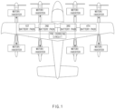
- FIG. 1 is a view illustrating the whole system structure of an electricity-driven fuselage.
- the electricity-driven fuselage may supply power necessary to drive a plurality of motors and/or inverters, as a plurality of battery packs are connected to each other in parallel.
- an initial inverter voltage is 0 V. Since the charged battery pack has a constant voltage, a pre-charging circuit may be provided to supply main power, if a battery pack voltage approximates an inverter voltage by charging the voltage of a capacitor provided at an inverter side to prevent surging.
- a capacitor may be at least one of various components included in a circuit constituting an inverter.
- the inverter may be a separate component that is connected (e.g., electrically connected) to the motor and physically separated from the motor.
- a method for balancing a battery pack using a pre-charging circuit and a device and a system for the same capable of ensuring safe starting and safe power supplying by performing voltage balancing between the battery packs, as well as the pre-charging of an inverter capacitor, by using the pre-charging circuit to supply battery power to the motor and/or the inverter.
- FIG. 1 illustrates that the method for balancing a battery pack using a pre-charging circuit is applied to an electricity-driven fuselage for the illustrative purpose.
- the method may be identically or similarly applied to an electric vehicle and another moving object driven by electricity.
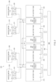
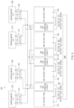
- FIG. 2 is a view illustrating a system for balancing a parallel battery pack using a pre-charging circuit.
- a system 200 for balancing the battery pack may include first to fourth battery packs 210, 220, 230, and 240, first to fourth pre-charging circuits 211, 221, 231, and 241 connected to the first to fourth battery packs 210, 220, 230, and 240, respectively, first to eighth inverters/motors 250, 260, 270, and 280 driven by receiving power charged in the first to fourth battery packs 210, 220, 230, and 240 through the first to fourth pre-charging circuits 211, 221, 231, and 241, first to eighth capacitors 251, 261, 271, and 281 interposed between the first to eighth inverters/motors 250, 260, 270, and 280, and the first to fourth pre-charging circuits 211, 221, 231, and 241 and charged with power for driving the respective inverters, and a battery management system 290 to monitor the state of each battery pack and control the relevant pre-charging circuit to perform voltage balancing between the battery packs connected to
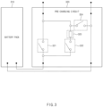
- FIG. 3 is a view illustrating the structure of a pre-charging circuit.
- the pre-charging relay 322 is a relay switch to charge a capacitor, which is provided at a front stage of an inverter/motor, to be at a voltage level similar to a voltage level of the battery pack.
- the balancing relay 324 is a relay switch to drop the voltage level of a relevant battery pack to lower the voltage difference between the battery packs to a specific level or less.
- the battery management system 290 may measure the voltage of each battery pack using a provided voltage sensor, as illustrated in FIG. 5 .
- the battery management system 290 may control the capacitor of the inverter/motor to be charged by turning on the pre-charging relay 322 in the state that the main relay 321 and the balancing relay 324 are turned off, as illustrated in FIG. 7 .
- a specific critical value e.g., a threshold value
- FIG. 4 is a flowchart illustrating a method for balancing battery packs connected to each other in parallel by using a pre-charging circuit.
- the battery pack management system 290 may calculate the voltage difference ( ⁇ V) between the maximum voltage (V max ) and the minimum voltage (V min ) by measuring the voltages of the battery packs connected to each other in parallel (S410).
- the battery management system 290 may turn off the pre-charging relay and the balancing relay after the voltage drops for a specific time (S450) and return to step 410 described above to calculate the voltage difference between the battery packs again.
- the battery management system 290 may perform a battery pack balancing operation on the second highest voltage battery pack in the same manner as in FIG. 4 if a voltage difference between the battery packs is not dropped to be the critical voltage or less even though the voltage of the battery pack, in which the maximum voltage ( V max ) is measured, is dropped.
- the battery pack balancing and the inverter/motor pre-charging are used only to connect a battery to an inverter at the initial state of a moving object. Accordingly, the battery pack balancing and the inverter/motor pre-charging are not used during flying (or operating). Accordingly, the weight of the moving object may need to be minimized.
- the battery management system may first measure a voltage of battery packs connected to each other in parallel, and compare the difference between the maximum voltage and the minimum voltage with an allowance value previously defined. If the voltage difference between battery packs is greater than the allowance value, the pre-charging relay, the balancing relay, and the relevant main relay of the common pre-charging circuit are controlled to be turned on, thereby performing the balancing operation for the relevant battery pack.
- the battery management system may sequentially perform balancing operations for the remaining battery packs until the voltage difference between the battery packs reaches the critical voltage, which is the target value.
- the battery management system 290 may turn off the pre-charging relay, the balancing relay, and the relevant negative main relay of the common pre-charging circuit after the voltage drops for a specific time (S1050) and return to step 1010 described above to calculate the voltage difference between the battery packs again.
- the battery management system 290 may repeatedly perform step 1010 to step 1050 until the voltage difference between the battery packs is the threshold value or less which is previously defined, thereby performing the battery pack balancing operation.
- a computing system 1000 may be applied to a battery management system of FIGS. 1 to 10 .
- the big data server may predict and manage the maximum output voltage and the remaining lifespan of the battery pack mounted for each vehicle periodically or in real time, based on various pieces of data collected from the electric vehicle.
- the computing system 1000 may, from the big data server, information on the optimal control parameter, for example, the threshold value of the voltage difference between the battery packs, which corresponds to the remaining lifespan. If the optimal control parameter of a relevant vehicle is changed or updated, the big data server may control to perform the optimal battery pack balancing by transmitting relevant information to the computing system 1000.
- the processor 1100 may be a central processing unit (CPU) or a semiconductor device for processing instructions stored in the memory 1300 and/or the storage 1600.
- CPU central processing unit
- Each of the memory 1300 and the storage 1600 may include various types of volatile or non-volatile storage media.
- the memory 1300 may include a read only memory (ROM) and a random access memory (RAM) .
- the operations of the methods or algorithms described in connection with the embodiments disclosed in the present disclosure may be directly implemented with a hardware module, a software module, or the combinations thereof, executed by the processor 1100.
- the software module may reside on a storage medium (e.g., the memory 1300 and/or the storage 1600), such as a RAM, a flash memory, a ROM, an erasable and programmable ROM (EPROM), an electrically EPROM (EEPROM), a register, a hard disc, a removable disc, or a compact disc-ROM (CD-ROM).
- the exemplary storage medium may be coupled to the processor 1100.
- the processor 1100 may read out information from the storage medium and may write information in the storage medium.
- the storage medium may be integrated with the processor 1100.
- the processor and storage medium may reside in an application specific integrated circuit (ASIC).
- the ASIC may reside in a user terminal.
- the processor and storage medium may reside as separate components of the user terminal.
- a method for balancing a parallel battery pack using a pre-charging circuit may be provided.
- An aspect of the present disclosure is to provide a method for balancing a parallel battery pack using a pre-charging circuit, capable of effectively balancing a battery pack connected in parallel without a separate charging unit to balance a battery pack by providing a balancing relay to a pre-charging circuit as well as a pre-charging relay, and a vehicle control device for the same, and a system including the same.
- An aspect of the present disclosure is to provide a method for balancing a parallel battery pack using a pre-charging circuit, capable of providing a common pre-charging circuit applied to all battery packs connected to each other in parallel in common, thereby reducing vehicle manufacturing costs and weight, a vehicle control device for the same, and a system including the same.
Landscapes
- Engineering & Computer Science (AREA)
- Power Engineering (AREA)
- Mechanical Engineering (AREA)
- Transportation (AREA)
- Aviation & Aerospace Engineering (AREA)
- Life Sciences & Earth Sciences (AREA)
- Sustainable Development (AREA)
- Sustainable Energy (AREA)
- Chemical & Material Sciences (AREA)
- Combustion & Propulsion (AREA)
- Physics & Mathematics (AREA)
- General Physics & Mathematics (AREA)
- Manufacturing & Machinery (AREA)
- Chemical Kinetics & Catalysis (AREA)
- Electrochemistry (AREA)
- General Chemical & Material Sciences (AREA)
- Charge And Discharge Circuits For Batteries Or The Like (AREA)
- Electric Propulsion And Braking For Vehicles (AREA)
Abstract
Description
- This application claims the benefit of priority to
Korean Patent Application No. 10-2022-0177527, filed in the Korean Intellectual Property Office on December 16, 2022 - The present disclosure relates to battery pack balancing, and more particularly, relates to a technology of balancing battery packs connected to each other in parallel by using a pre-charging circuit.
- In general, a battery pack is provided in the form of a module by stacking several cells (single cells) of battery. Accordingly, cell balancing among the multiple battery cells is significantly important.
- The cell balancing is important because the cells may have different charging speeds due to the unbalance between cells resulting in a possible overcharge of an individual cell(s). The voltage of an overcharged cell may exceed the voltage limit (e.g., end-of-charge voltage).
- The cell having the cell voltage exceeding the end-of charge voltage may get damaged or may have the risk of explosion.
- To alleviate this risk, a cell balancing circuit connected to a battery management system (BMS) is necessarily applied to the battery pack, such that the cell balancing is implemented in charging.
- The present disclosure has been made to solve the above-mentioned problems occurring in the prior art while advantages achieved by the prior art are maintained intact.
- An aspect of the present disclosure provides a method for balancing a parallel battery pack using a pre-charging circuit, and an apparatus and a system therefor.
- According to the present disclosure, a method may include: detecting a state of charge (SOC) of each of a plurality of battery packs that provide power to an electricity-driven apparatus, wherein the plurality of battery packs are connected in parallel; calculating, based on the detected SOC, a voltage difference between the plurality of battery packs; and performing, by one or more pre-charging circuits including a balancing relay, battery pack balancing, based on the calculated voltage difference exceeding a threshold value.
- Each of the one or more pre-charging circuits corresponds to one of the plurality of battery packs. Each pre-charging circuit of the one or more pre-charging circuits may include: a pre-charging relay connected to a resistor in series. Performing of the battery pack balancing may include dropping, by at least one pre-charging circuit of the one or more pre-charging circuits, to drop a voltage of a corresponding battery pack by joule heating of the resistor.
- Performing of the battery pack balancing may include: identifying, based on the detected SOC, a battery pack, of the plurality of battery packs, that has a maximum voltage; and dropping a voltage of the battery pack having the maximum voltage by turning on, for a specific time, a pre-charging relay and the balancing relay of a pre-charging circuit of the one or more pre-charging circuits. The pre-charging circuit may correspond to the battery pack having the maximum voltage.
- Performing of the battery pack balancing may further include: turning off the pre-charging relay and the balancing relay after the specific time has elapsed; re-measuring a voltage of each battery pack of the plurality of battery packs; and recalculating the voltage difference based on the re-measured voltages.
- The method may further include sequentially repeating the battery pack balancing based on the re-measured voltages, until the re-calculated voltage difference reaches a threshold value.
- The method may further include performing a pre-charging operation of charging a capacitor, of an inverter connected to a motor of the electricity-driven apparatus, by turning on a pre-charging relay of the one or more pre-charging circuits, based on the calculated voltage difference being less than or equal to a threshold value.
- The one or more pre-charging circuits may include a main relay and a pre-charging relay. The method may further include supplying power to an inverter, connected to a motor of the electricity-driven apparatus, by turning off the pre-charging relay and turning on the main relay, based on a capacitor of the inverter being fully charged.
- Calculating of the voltage difference between the plurality of battery packs may include: identifying, among the plurality of battery packs, a first battery pack that has a maximum voltage of the plurality of battery packs; and identifying, among the plurality of battery packs, a second battery pack that has a minimum voltage of the plurality of battery packs. The voltage difference may be calculated as a difference between the maximum voltage and the minimum voltage.
- A pre-charging circuit, of the one or more pre-charging circuits, may be connected to the plurality of battery packs.
- The electricity-driven apparatus may include at least one of an electric vehicle or an unmanned aerial vehicle.
- According to the present disclosure, an electricity-driven apparatus may include: a plurality of battery packs connected to each other in parallel; a plurality of inverters connected to motors driven by power provided by the plurality of battery packs; one or more pre-charging circuits including a balancing relay and interposed between the plurality of battery packs and the plurality of inverters; and a battery management system configured to control the one or more pre-charging circuits to perform battery pack balancing. The battery management system may be further configured to control the balancing relay to perform the battery pack balancing.
- Each of the one or more pre-charging circuits may correspond to a respective one of the plurality of battery packs. The one or more pre-charging circuits may include a pre-charging relay connected to a resistor in series. The one or more pre-charging circuits may be configured to drop a voltage of a battery pack of the plurality of battery packs by joule heating of the resistor.
- The battery management system may be further configured to: detect a state of charge (SOC) of each of the plurality of battery packs; calculate a voltage difference between the plurality of battery packs based on the detected SOC; and perform the battery pack balancing based on the calculated voltage difference exceeding a threshold value.
- The battery management system may be further configured to: identify, based on a state of charge (SOC) of each of the plurality of battery packs, a battery pack, of the plurality of battery packs, that has a maximum voltage; and drop a voltage of the battery pack having the maximum voltage by turning on, for a specific time, a pre-charging relay and the balancing relay of a pre-charging circuit of the one or more pre-charging circuits. The pre-charging circuit may correspond to the battery pack having the maximum voltage.
- The battery management system may be further configured to: turn off the pre-charging relay and the balancing relay after the specific time has elapsed; and measure a voltage of each battery pack of the plurality of battery packs; and calculate, based on the measured voltages, a voltage difference between the plurality of battery packs.
- The battery management system may be further configured to sequentially repeat the battery pack balancing based on the measured voltages, until the calculated voltage difference reaches a threshold value.
- The battery management system may be further configured to perform a pre-charging operation of charging capacitors, of the plurality of inverters, by turning on a pre-charging relay of the one or more pre-charging circuits, based on a voltage difference between the plurality of battery packs being less than or equal to a threshold value.
- The one or more pre-charging circuits may include: a main relay; and a pre-charging relay. The battery management system may be further configured to, based on capacitors of the plurality of inverters being fully charged, supply power to the plurality of inverters by turning off the pre-charging relay and turning on the main relay.
- The battery management system may be configured to calculate the voltage difference based on a maximum voltage and a minimum voltage of the plurality of battery packs.
- A pre-charging circuit, of the one or more pre-charging circuits, may be connected to the plurality of battery packs.
- The above and other objects, features and advantages of the present disclosure will be more apparent from the following detailed description taken in conjunction with the accompanying drawings:
-
FIG. 1 is a view illustrating the whole system structure of an electricity-driven fuselage. -
FIG. 2 is a view illustrating a system for balancing a parallel battery pack using a pre-charging circuit. -
FIG. 3 is a view illustrating the structure of a pre-charging circuit. -
FIG. 4 is a flowchart illustrating a method for balancing battery packs connected to each other in parallel by using a pre-charging circuit. -
FIGS. 5 to 8 are views illustrating a procedure for balancing the battery packs connected to each other in parallel using a pre-charging circuit. -
FIG. 9 illustrates a system structure for performing battery pack balancing using a common pre-charging circuit. -
FIG. 10 is a flowchart illustrating a method for balancing battery packs connected in parallel using the common pre-charging circuit. -
FIG. 11 illustrates a computing system. - Hereinafter, some embodiments of the present disclosure will be described in detail with reference to the exemplary drawings. In adding the reference numerals to the components of each drawing, it should be noted that the identical or equivalent component is designated by the identical numeral even if they are displayed on other drawings. Further, in describing the embodiment of the present disclosure, a detailed description of well-known features or functions will be ruled out in order not to unnecessarily obscure the gist of the present disclosure.
- In addition, in the following description of components, the terms 'first', 'second', 'A', 'B', '(a)', and `(b)' may be used. These terms are merely intended to distinguish one component from another component, and the terms do not limit the nature, sequence or order of the constituent components. In addition, unless otherwise defined, all terms used herein, including technical or scientific terms, have the same meanings as those generally understood by those skilled in the art to which the present disclosure pertains. Such terms as those defined in a generally used dictionary are to be interpreted as having meanings equal to the contextual meanings in the relevant field of art, and are not to be interpreted as having ideal or excessively formal meanings unless clearly defined as having such in the present application.
- In general, a cell balancing circuit senses the voltage of each cell and bypasses the energy, which is supplied after the full charging of the cell, to a resistor, such that the energy is consumed in the form of heat.
- Therefore, if the battery pack is charged with power, the cell balancing circuit senses whether the cell is fully charged. If the full charging of the cell is determined, the supplied charging energy may be controlled such that the voltage of the cell is not increased beyond the end-of-charged.
- In general, a plurality of battery packs are provided in an electricity-powered moving object while being mounted through in serial connection or in parallel connection. If the battery packs are connected to each other in parallel, and if different voltage states are present between the battery packs, an electrical spark may occur. If the voltage difference is significantly high between the battery packs, it may start a fire. In particular, if a lithium ion battery is applied, the lithium ion battery has higher energy as compared with some other types of batteries. Accordingly, if battery packs having mutually different voltage levels are connected to each other in parallel, components, such as a motor or an inverter, connected to the battery pack may be damaged.
- To solve the problem discussed above, the state of charge (SOC) of each of battery packs connected to each other in parallel may be measured. The battery pack having the smallest SOC may be charged with power such that the SOC of the battery pack is matched to be equal to the highest SOC.
- However, according to the above technology, an additional charging device may be provided in an urban air mobility (UAM) or an electric vehicle mounted with a parallel battery pack. Accordingly, the user has to connect the charging cable to the UAM or the electric vehicle every the device is to be started, which may negatively impact the user experience.
- Hereinafter, embodiments of the present disclosure will be described with reference to
FIGS. 1 to 11 . -
FIG. 1 is a view illustrating the whole system structure of an electricity-driven fuselage. - Referring to
FIG. 1 , the electricity-driven fuselage may supply power necessary to drive a plurality of motors and/or inverters, as a plurality of battery packs are connected to each other in parallel. - As illustrated in
FIG. 1 , if power charged in battery packs connected to each other in parallel is used as a power source for a plurality of motors/inverters, an initial inverter voltage is 0 V. Since the charged battery pack has a constant voltage, a pre-charging circuit may be provided to supply main power, if a battery pack voltage approximates an inverter voltage by charging the voltage of a capacitor provided at an inverter side to prevent surging. For example, a capacitor may be at least one of various components included in a circuit constituting an inverter. For example, the inverter may be a separate component that is connected (e.g., electrically connected) to the motor and physically separated from the motor. - If a voltage difference in a specific level or more is made between the battery packs connected to each other in parallel, a spark may be caused, seriously, smoke or a flare may be caused in various relays and/or switches used for the parallel-connection between the battery packs. Accordingly, a constant voltage difference needs to be made between battery packs to safely supply the power to the motor and/or the inverter as the battery packs are connected to each other in parallel.
- In the present suggestion, the following description will be made regarding a method for balancing a battery pack using a pre-charging circuit and a device and a system for the same, capable of ensuring safe starting and safe power supplying by performing voltage balancing between the battery packs, as well as the pre-charging of an inverter capacitor, by using the pre-charging circuit to supply battery power to the motor and/or the inverter.
-
FIG. 1 illustrates that the method for balancing a battery pack using a pre-charging circuit is applied to an electricity-driven fuselage for the illustrative purpose. For example, the method may be identically or similarly applied to an electric vehicle and another moving object driven by electricity. -
FIG. 2 is a view illustrating a system for balancing a parallel battery pack using a pre-charging circuit. - Referring to
FIG. 2 , asystem 200 for balancing the battery pack may include first to fourth battery packs 210, 220, 230, and 240, first to fourthpre-charging circuits motors pre-charging circuits eighth capacitors motors pre-charging circuits battery management system 290 to monitor the state of each battery pack and control the relevant pre-charging circuit to perform voltage balancing between the battery packs connected to each other in parallel. - Although the description made with reference to
FIG. 2 , regarding driving eighth motors/inverts by connecting four battery packs in parallel, the number of the battery packs connected to each other in parallel and the number of inverts/motors to receive power from the plurality of battery packs may be varied, depending on the design of those skilled in the art, and the usage and the structure of a relevant moving object. - The detailed structure of the pre-charging circuit and an operation of controlling the pre-charging circuit for battery pack balancing in the
battery management system 290 will be described in more detail with reference to accompanying drawings. -
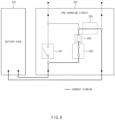
FIG. 3 is a view illustrating the structure of a pre-charging circuit. - Referring to
FIG. 3 , thepre-charging circuit 320 may include amain relay 321, apre-charging relay 322, aresistor 323, and abalancing relay 324. - The
main relay 321 is a relay switch for supplying main power to an inverter/motor. - The
pre-charging relay 322 is a relay switch to charge a capacitor, which is provided at a front stage of an inverter/motor, to be at a voltage level similar to a voltage level of the battery pack. - The balancing
relay 324 is a relay switch to drop the voltage level of a relevant battery pack to lower the voltage difference between the battery packs to a specific level or less. - Hereinafter, the detailed procedure for controlling the pre-charging circuit by the
battery management system 290 to perform the battery pack balancing will be described with reference toFIG. 3 andFIGS. 5 to 8 . -
FIGS. 5 to 8 are views illustrating a procedure for balancing the battery packs connected to each other in parallel using a pre-charging circuit. - The
battery management system 290 may measure the voltage of each battery pack using a provided voltage sensor, as illustrated inFIG. 5 . - The
battery management system 290 may determine that battery pack balancing is required, if a voltage difference between battery packs exceeds a specific critical voltage. - The
battery management system 290 may control thepre-charging circuit 320 to drop the voltage of the battery pack having the maximum voltage. - As illustrated in
FIG. 6 , thebattery management system 290 may turn on thepre-charging relay 322 and the balancingrelay 324 in the state that themain relay 321 is turned off to drop the voltage of thebattery pack 310. In this case, Joule heating occurs due to aresistor 323. Accordingly, the charging power of thebattery pack 310 may be reduced, such that an output voltage of thebattery pack 310 is dropped. - If the
battery management system 290 determines the voltage difference between the battery packs as being dropped to a specific critical value (e.g., a threshold value) or less, by monitoring the voltage drop of thebattery pack 310, thebattery management system 290 may control the capacitor of the inverter/motor to be charged by turning on thepre-charging relay 322 in the state that themain relay 321 and the balancingrelay 324 are turned off, as illustrated inFIG. 7 . - If the charging of the capacitor of the motor/inverter is completed, the
battery management system 290 may control supplying main power to the inverter/motor by turning on themain relay 321, in the state that thepre-charging relay 322 and the balancingrelay 324 are turned off, as illustrated inFIG. 8 . -
FIG. 4 is a flowchart illustrating a method for balancing battery packs connected to each other in parallel by using a pre-charging circuit. - Referring to
FIG. 4 , the batterypack management system 290 may calculate the voltage difference (ΔV) between the maximum voltage (V max ) and the minimum voltage (V min ) by measuring the voltages of the battery packs connected to each other in parallel (S410). - The
battery management system 290 may determine whether the voltage difference ΔV between the battery packs exceeds a critical voltage (V critical ) which is previously defined (S420) . - Accordingly of the determination, if the voltage difference ΔV exceeds the critical voltage (V critical ), the
battery management system 290 may turn on the pre-charging relay and the balancing relay of the pre-charging circuit corresponding to the battery pack in which the maximum voltage is measured (S430). In this case, it should be noted that the main relay is turned off. - The
battery management system 290 may drop the voltage of the relevant battery pack by maintaining the pre-charging relay and the balancing relay to be turned on for a specific time (S440) . In this case, the voltage of the battery pack may be dropped through Joule heating by the resistor provided in the relevant pre-charging circuit. - The
battery management system 290 may turn off the pre-charging relay and the balancing relay after the voltage drops for a specific time (S450) and return to step 410 described above to calculate the voltage difference between the battery packs again. - If the voltage difference between the battery packs is equal to or less than the specific critical or less in S420, the
battery management system 290 turns on the pre-charging relay of the pre-charging circuit until the capacitor of the inverter/motor is charged to be in a specific level. If the capacitor is charged with power to be in the specific level or more, thebattery management system 290 turns off the pre-charging relay and turns on the main relay such that the main power is supplied to the inverter/motor (S460) - The
battery management system 290 may perform a battery pack balancing operation on the second highest voltage battery pack in the same manner as inFIG. 4 if a voltage difference between the battery packs is not dropped to be the critical voltage or less even though the voltage of the battery pack, in which the maximum voltage ( V max ) is measured, is dropped. - The
battery management system 290 may sequentially perform a battery pack balancing operation on the remaining battery packs until a voltage difference between the battery packs reaches a critical voltage or less, which is a target voltage. -
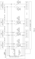
FIG. 9 illustrates a system structure for performing battery pack balancing using a common pre-charging circuit. - The battery pack balancing and the inverter/motor pre-charging are used only to connect a battery to an inverter at the initial state of a moving object. Accordingly, the battery pack balancing and the inverter/motor pre-charging are not used during flying (or operating). Accordingly, the weight of the moving object may need to be minimized.
- To this end, the common pre-charging circuit may be applied for all battery packs connected to each other in parallel in common, instead of an individual pre-charging circuit for each battery pack, as described above with reference to
FIGS. 1 to 8 ,
Although the principle of balancing the battery packs connected to each other in parallel and the principle of inverter/motor pre-charging are the same as the operating principle of the pre-charging circuit ofFIGS. 1 to 8 , the number of the pre-charging relay, the resistor, and the balancing relay may be reduced in proportion to the number of the system illustrated inFIG. 9 . Accordingly, the weight of the moving object may be reduced. - Referring to
FIG. 9 , according to the characteristic of the suggested system circuit, a plus (+) terminal and a minus (-) terminal of each battery pack are connected to a positive main relay and a negative main relay, and the relay circuit for pre-charging and balancing are, in common, applied to all battery packs. - The battery management system may first measure a voltage of battery packs connected to each other in parallel, and compare the difference between the maximum voltage and the minimum voltage with an allowance value previously defined. If the voltage difference between battery packs is greater than the allowance value, the pre-charging relay, the balancing relay, and the relevant main relay of the common pre-charging circuit are controlled to be turned on, thereby performing the balancing operation for the relevant battery pack.
- The battery management system may sequentially perform balancing operations for the remaining battery packs until the voltage difference between the battery packs reaches the critical voltage, which is the target value.
- After the balancing of the battery pack is completed, the battery management system may perform the pre-charging operation of charging the capacitor of the inverter/motor by controlling turning off the balancing relay and turning on the pre-charging relay and the negative main relay.
- After the pre-charging operation is completed, the battery management system may control turning off the pre-charging relay and turning on the positive main relay and the negative main relay of the battery pack, such that the main power is supplied to the inverter/motor.
-
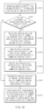
FIG. 10 is a flowchart illustrating a method for balancing battery packs connected in parallel using the common pre-charging circuit. - Referring to
FIG. 10 , the batterypack management system 290 may calculate the voltage difference (ΔV) between the maximum voltage (V max ) and the minimum voltage (V min ) by measuring the voltages of the battery packs connected to each other in parallel (S1010). - The
battery management system 290 may determine whether the voltage difference ΔV between the battery packs exceeds a specific critical voltage (Vcritical ) (51020) . - Accordingly of the determination, if the voltage difference ΔV exceeds the critical voltage (V critical ), the
battery management system 290 may turn on the pre-charging relay and the balancing relay of the common pre-charging circuit and may turn on the negative main relay of the battery pack in which the maximum voltage is measured (S1030). - The
battery management system 290 may drop the voltage of the relevant battery pack by maintaining the pre-charging relay and the balancing relay to be turned on for a specific time (S1040). In this case, the voltage of the battery pack may be dropped through Joule heating by the resistor provided in the relevant pre-charging circuit. - The
battery management system 290 may turn off the pre-charging relay, the balancing relay, and the relevant negative main relay of the common pre-charging circuit after the voltage drops for a specific time (S1050) and return to step 1010 described above to calculate the voltage difference between the battery packs again. - The
battery management system 290 may repeatedly perform step 1010 to step 1050 until the voltage difference between the battery packs is the threshold value or less which is previously defined, thereby performing the battery pack balancing operation. - If the voltage difference between the battery packs is equal to or less than the threshold value or less, which is previously defined, in S1020, the
battery management system 290 may control turning on the pre-charging relay of the common pre-charging circuit and the negative main relay of each battery pack in the state that the balancing relay of the common pre-charging circuit is turned off, until the capacitor of the inverter/motor is charged to a specific level, thereby performing the pre-charging operation of charging the capacitor of the inverter/motor with power. - After the pre-charging operation is completed, the
battery management system 290 may control turning on the positive main relay and the negative main relay of each battery pack after turning off the pre-charging relay of the common pre-charging circuit to supply main power to the inverter/motor (S1070). -
FIG. 11 illustrates a computing system. - A
computing system 1000 may be applied to a battery management system ofFIGS. 1 to 10 . - Referring to
FIG. 11 , acomputing system 1000 may include at least oneprocessor 1100, amemory 1300, a userinterface input device 1400, a userinterface output device 1500, astorage 1600, and anetwork interface 1700, which are connected with each other via abus 1200. - The
computing system 1000 may access an external server, such as a big data server or a cloud server, of a vehicle through thenetwork interface 1700 to acquire various pieces of information necessary for battery pack balancing using the pre-charging circuit and may retain the acquired information to thememory 1300. - For example, the
computing system 1000 may acquire, from the external server, information on a threshold value for a voltage difference between the battery packs, which is a parameter for determining whether to perform the battery pack balancing. The minimum battery pack voltage value and/or the maximum battery pack voltage value required for the driving of an electric vehicle may be varied depending on the driving and the driving pattern of the driver. For example, a driving pattern of a driver enjoying higher-speed driving and a higher acceleration and a driving pattern of a driver enjoying lower-speed driving and a lower acceleration may be different from each other in terms of the required level of an output voltage of a battery pack, and thus may be different from each other in terms of a time point for starting the battery pack balancing and a critical voltage value related to a battery pack voltage difference for determining whether to start the battery pack balancing. - In addition, the charging/discharging capacity and the maximum output voltage of the battery pack may be varied depending on the remaining lifespan of the battery pack and the temperature of the battery pack. Accordingly, the time point for starting the battery pack balancing and the starting condition of the battery pack balancing may be differently defined.
- The big data server may predict and manage the maximum output voltage and the remaining lifespan of the battery pack mounted for each vehicle periodically or in real time, based on various pieces of data collected from the electric vehicle. The
computing system 1000 may, from the big data server, information on the optimal control parameter, for example, the threshold value of the voltage difference between the battery packs, which corresponds to the remaining lifespan. If the optimal control parameter of a relevant vehicle is changed or updated, the big data server may control to perform the optimal battery pack balancing by transmitting relevant information to thecomputing system 1000. - The
processor 1100 may be a central processing unit (CPU) or a semiconductor device for processing instructions stored in thememory 1300 and/or thestorage 1600. Each of thememory 1300 and thestorage 1600 may include various types of volatile or non-volatile storage media. For example, thememory 1300 may include a read only memory (ROM) and a random access memory (RAM) . - Thus, the operations of the methods or algorithms described in connection with the embodiments disclosed in the present disclosure may be directly implemented with a hardware module, a software module, or the combinations thereof, executed by the
processor 1100. The software module may reside on a storage medium (e.g., thememory 1300 and/or the storage 1600), such as a RAM, a flash memory, a ROM, an erasable and programmable ROM (EPROM), an electrically EPROM (EEPROM), a register, a hard disc, a removable disc, or a compact disc-ROM (CD-ROM). - The exemplary storage medium may be coupled to the
processor 1100. Theprocessor 1100 may read out information from the storage medium and may write information in the storage medium. Alternatively, the storage medium may be integrated with theprocessor 1100. The processor and storage medium may reside in an application specific integrated circuit (ASIC). The ASIC may reside in a user terminal. Alternatively, the processor and storage medium may reside as separate components of the user terminal. - According to the present disclosure, there may be provided a method for balancing a parallel battery pack using a pre-charging circuit, and an apparatus and a system for the same.
- An aspect of the present disclosure is to provide a method for balancing a parallel battery pack using a pre-charging circuit, capable of effectively balancing a battery pack connected in parallel without a separate charging unit to balance a battery pack by providing a balancing relay to a pre-charging circuit as well as a pre-charging relay, and a vehicle control device for the same, and a system including the same.
- An aspect of the present disclosure is to provide a method for balancing a parallel battery pack using a pre-charging circuit, capable of providing a common pre-charging circuit applied to all battery packs connected to each other in parallel in common, thereby reducing vehicle manufacturing costs and weight, a vehicle control device for the same, and a system including the same.
- Besides, a variety of effects directly or indirectly understood through the disclosure may be provided.
- The above description is merely an example of the technical idea of the present disclosure, and various modifications and modifications may be made by one skilled in the art without departing from the essential characteristic of the present disclosure.
- Accordingly, embodiments of the present disclosure are intended not to limit but to explain the technical idea of the present disclosure, and the scope and spirit of the present disclosure is not limited by the above embodiments. The scope of protection of the present disclosure should be construed by the attached claims, and all equivalents thereof should be construed as being included within the scope of the present disclosure.
- Hereinabove, although the present disclosure has been described with reference to exemplary embodiments and the accompanying drawings, the present disclosure is not limited thereto, but may be variously modified and altered by those skilled in the art to which the present disclosure pertains without departing from the spirit and scope of the present disclosure claimed in the following claims.
Claims (15)
- A method comprising:detecting a state of charge (SOC) of each of a plurality of battery packs that provide power to an electricity-driven apparatus, wherein the plurality of battery packs are connected in parallel;calculating, based on the detected SOC, a voltage difference between the plurality of battery packs; andperforming, by one or more pre-charging circuits comprising a balancing relay, battery pack balancing, based on the calculated voltage difference exceeding a threshold value.
- The method of claim 1, wherein each of the one or more pre-charging circuits corresponds to one of the plurality of battery packs,wherein each pre-charging circuit of the one or more pre-charging circuits comprises:
a pre-charging relay connected to a resistor in series, andwherein the performing of the battery pack balancing comprises dropping, by at least one pre-charging circuit of the one or more pre-charging circuits, to drop a voltage of a corresponding battery pack by joule heating of the resistor. - The method of claim 1 or 2, wherein the performing of the battery pack balancing comprises:identifying, based on the detected SOC, a battery pack, of the plurality of battery packs, that has a maximum voltage; anddropping a voltage of the battery pack having the maximum voltage by turning on, for a specific time, a pre-charging relay and the balancing relay of a pre-charging circuit of the one or more pre-charging circuits, wherein the pre-charging circuit corresponds to the battery pack having the maximum voltage.
- The method of claim 3, wherein the performing of the battery pack balancing further comprises:turning off the pre-charging relay and the balancing relay after the specific time has elapsed;re-measuring a voltage of each battery pack of the plurality of battery packs; andrecalculating the voltage difference based on the re-measured voltages.
- The method of claim 4, further comprising sequentially repeating the battery pack balancing based on the re-measured voltages, until the re-calculated voltage difference reaches a threshold value.
- The method of anyone of claims 1-5, further comprising performing a pre-charging operation of charging a capacitor, of an inverter connected to a motor of the electricity-driven apparatus, by turning on a pre-charging relay of the one or more pre-charging circuits, based on the calculated voltage difference being less than or equal to a threshold value.
- The method of anyone of claims 1-6, wherein the one or more pre-charging circuits comprise a main relay and a pre-charging relay, and
wherein the method further comprises supplying power to an inverter, connected to a motor of the electricity-driven apparatus, by turning off the pre-charging relay and turning on the main relay, based on a capacitor of the inverter being fully charged. - The method of anyone of claims 1-7, wherein the calculating of the voltage difference between the plurality of battery packs comprises:identifying, among the plurality of battery packs, a first battery pack that has a maximum voltage of the plurality of battery packs; andidentifying, among the plurality of battery packs, a second battery pack that has a minimum voltage of the plurality of battery packs,wherein the voltage difference is calculated as a difference between the maximum voltage and the minimum voltage.
- The method of anyone of claims 1-8, wherein a pre-charging circuit, of the one or more pre-charging circuits, is connected to the plurality of battery packs.
- The method of anyone of claims 1-9, wherein the electricity-driven apparatus comprises at least one of an electric vehicle or an unmanned aerial vehicle.
- An electricity-driven apparatus comprising:a plurality of battery packs connected to each other in parallel;a plurality of inverters connected to motors driven by power provided by the plurality of battery packs;one or more pre-charging circuits comprising a balancing relay and interposed between the plurality of battery packs and the plurality of inverters; anda battery management system configured to control the one or more pre-charging circuits to perform battery pack balancing,wherein the battery management system is further configured to control the balancing relay to perform the battery pack balancing.
- The electricity-driven apparatus of claim 11, wherein each of the one or more pre-charging circuits corresponds to a respective one of the plurality of battery packs,wherein the one or more pre-charging circuits comprise a pre-charging relay connected to a resistor in series, andwherein the one or more pre-charging circuits are configured to drop a voltage of a battery pack of the plurality of battery packs by joule heating of the resistor.
- The electricity-driven apparatus of claim 12, wherein the battery management system is further configured to:detect a state of charge (SOC) of each of the plurality of battery packs;calculate a voltage difference between the plurality of battery packs based on the detected SOC; andperform the battery pack balancing based on the calculated voltage difference exceeding a threshold value.
- The electricity-driven apparatus of anyone of claims 11-13, wherein the battery management system is further configured to:identify, based on a state of charge (SOC) of each of the plurality of battery packs, a battery pack, of the plurality of battery packs, that has a maximum voltage; anddrop a voltage of the battery pack having the maximum voltage by turning on, for a specific time, a pre-charging relay and the balancing relay of a pre-charging circuit of the one or more pre-charging circuits, wherein the pre-charging circuit corresponds to the battery pack having the maximum voltage.
- The electricity-driven apparatus of claim 14, wherein the battery management system is further configured to:turn off the pre-charging relay and the balancing relay after the specific time has elapsed; andmeasure a voltage of each battery pack of the plurality of battery packs; andcalculate, based on the measured voltages, a voltage difference between the plurality of battery packs.
Applications Claiming Priority (1)
| Application Number | Priority Date | Filing Date | Title |
|---|---|---|---|
| KR1020220177527A KR20240095698A (en) | 2022-12-16 | 2022-12-16 | Method for balancing parallel battery pack using pre-charging circuit and apparatus and system therefor |
Publications (2)
| Publication Number | Publication Date |
|---|---|
| EP4395114A1 true EP4395114A1 (en) | 2024-07-03 |
| EP4395114B1 EP4395114B1 (en) | 2025-12-31 |
Family
ID=88745736
Family Applications (1)
| Application Number | Title | Priority Date | Filing Date |
|---|---|---|---|
| EP23208543.1A Active EP4395114B1 (en) | 2022-12-16 | 2023-11-08 | Method for balancing parallel battery packs using pre-charging circuit and apparatus and system for the same |
Country Status (3)
| Country | Link |
|---|---|
| US (1) | US12351070B2 (en) |
| EP (1) | EP4395114B1 (en) |
| KR (1) | KR20240095698A (en) |
Families Citing this family (7)
| Publication number | Priority date | Publication date | Assignee | Title |
|---|---|---|---|---|
| US12500436B2 (en) * | 2021-10-20 | 2025-12-16 | China Energy Investment Corporation Limited | Controller, system, and method for managing discharge or charge of heterogeneous battery packs |
| FR3147258A1 (en) * | 2023-03-31 | 2024-10-04 | Honda Motor Co., Ltd. | Power supply system, moving object comprising the power supply system, and method for controlling the power supply system |
| FR3147259A1 (en) * | 2023-03-31 | 2024-10-04 | Honda Motor Co., Ltd. | Power supply system, moving object comprising the power supply system, and method for controlling the power supply system |
| JP2024143933A (en) * | 2023-03-31 | 2024-10-11 | 本田技研工業株式会社 | Power supply system and mobile body equipped with power supply system |
| JP2024143924A (en) * | 2023-03-31 | 2024-10-11 | 本田技研工業株式会社 | Power supply system and mobile body equipped with power supply system |
| US20240348065A1 (en) * | 2023-04-11 | 2024-10-17 | Caterpillar Inc. | Battery system charge level management |
| KR102925495B1 (en) * | 2024-08-14 | 2026-02-11 | 타타대우모빌리티 주식회사 | Precharging device for electric commercial vehicle and control method thereof |
Citations (6)
| Publication number | Priority date | Publication date | Assignee | Title |
|---|---|---|---|---|
| US20140306666A1 (en) * | 2013-04-11 | 2014-10-16 | Sk Innovation Co., Ltd. | Apparatus and Method for Battery Balancing |
| US20210082480A1 (en) * | 2017-11-06 | 2021-03-18 | Lg Chem, Ltd. | Cell module equalization and precharge device and method |
| US20210273462A1 (en) * | 2017-04-24 | 2021-09-02 | O2Micro, Inc. | Open cell detection method and open cell recovery detection method in a battery management system |
| CN115117974A (en) * | 2022-07-19 | 2022-09-27 | 珠海格力电器股份有限公司 | Battery pack balance control method and device, battery system and storage medium |
| US20220311269A1 (en) * | 2021-03-29 | 2022-09-29 | Honda Motor Co., Ltd. | Battery control apparatus for power supply system |
| US20220376519A1 (en) * | 2020-02-03 | 2022-11-24 | Lg Energy Solution, Ltd. | Individual discharge system and method for battery racks |
Family Cites Families (14)
| Publication number | Priority date | Publication date | Assignee | Title |
|---|---|---|---|---|
| FR2926934B1 (en) | 2008-01-29 | 2010-09-17 | Saft Groupe Sa | ELECTRONIC SYSTEM FOR BATTERY |
| KR101367875B1 (en) * | 2011-03-21 | 2014-02-26 | 주식회사 엘지화학 | Apparatus for controlling connection of battery pack |
| JP2014050129A (en) * | 2012-08-29 | 2014-03-17 | Toyota Motor Corp | Power unit |
| JP2015166710A (en) * | 2014-03-04 | 2015-09-24 | ソニー株式会社 | Electric storage member state estimation apparatus, battery pack, electric vehicle, electric storage device, and electric storage member state estimation method |
| KR101882286B1 (en) | 2014-11-18 | 2018-07-27 | 주식회사 엘지화학 | Battery Pack Having Voltage Valancing Syetem |
| KR20170053071A (en) * | 2015-11-05 | 2017-05-15 | 현대자동차주식회사 | Vehicle battery apparatus |
| KR102284872B1 (en) | 2017-10-31 | 2021-07-30 | 주식회사 엘지에너지솔루션 | Cell balancing apparatus and method |
| JP7020108B2 (en) * | 2017-12-25 | 2022-02-16 | トヨタ自動車株式会社 | Abnormality diagnosis method for secondary battery system and assembled battery |
| KR102217590B1 (en) | 2018-07-16 | 2021-02-18 | 주식회사 엘지화학 | Apparatus and method for battery balancing |
| WO2020024163A1 (en) | 2018-08-01 | 2020-02-06 | 深圳市大疆创新科技有限公司 | Intelligent battery control method, intelligent battery, and unmanned aerial vehicle |
| KR102244141B1 (en) | 2018-10-12 | 2021-04-22 | 주식회사 엘지화학 | Apparatus and method for battery management |
| US11108251B2 (en) | 2019-02-22 | 2021-08-31 | Aurora Flight Sciences Corporation | Battery management system |
| US11133534B2 (en) | 2019-02-22 | 2021-09-28 | Aurora Flight Sciences Corporation | Programmable battery pack |
| US11967842B2 (en) | 2020-10-09 | 2024-04-23 | The Boeing Company | Smart battery disconnect and protection architecture for airborne high-power modular multi-string battery pack |
-
2022
- 2022-12-16 KR KR1020220177527A patent/KR20240095698A/en active Pending
-
2023
- 2023-05-22 US US18/200,209 patent/US12351070B2/en active Active
- 2023-11-08 EP EP23208543.1A patent/EP4395114B1/en active Active
Patent Citations (6)
| Publication number | Priority date | Publication date | Assignee | Title |
|---|---|---|---|---|
| US20140306666A1 (en) * | 2013-04-11 | 2014-10-16 | Sk Innovation Co., Ltd. | Apparatus and Method for Battery Balancing |
| US20210273462A1 (en) * | 2017-04-24 | 2021-09-02 | O2Micro, Inc. | Open cell detection method and open cell recovery detection method in a battery management system |
| US20210082480A1 (en) * | 2017-11-06 | 2021-03-18 | Lg Chem, Ltd. | Cell module equalization and precharge device and method |
| US20220376519A1 (en) * | 2020-02-03 | 2022-11-24 | Lg Energy Solution, Ltd. | Individual discharge system and method for battery racks |
| US20220311269A1 (en) * | 2021-03-29 | 2022-09-29 | Honda Motor Co., Ltd. | Battery control apparatus for power supply system |
| CN115117974A (en) * | 2022-07-19 | 2022-09-27 | 珠海格力电器股份有限公司 | Battery pack balance control method and device, battery system and storage medium |
Also Published As
| Publication number | Publication date |
|---|---|
| KR20240095698A (en) | 2024-06-26 |
| US20240198854A1 (en) | 2024-06-20 |
| EP4395114B1 (en) | 2025-12-31 |
| US12351070B2 (en) | 2025-07-08 |
Similar Documents
| Publication | Publication Date | Title |
|---|---|---|
| EP4395114B1 (en) | Method for balancing parallel battery packs using pre-charging circuit and apparatus and system for the same | |
| EP3223387B1 (en) | Apparatus and method for voltage balancing between battery racks | |
| CN105703447B (en) | Direct Balance Charging Method for Rechargeable Batteries | |
| CN112789780A (en) | Battery equalization method, intelligent battery, charging system and storage medium | |
| US10532665B2 (en) | Method for battery management of a battery with a charge state compensation system and battery management system | |
| US8264201B2 (en) | Battery management system and driving method thereof | |
| EP2418751B1 (en) | Battery charger and battery charging method | |
| JP6802723B2 (en) | Power storage device and power storage control method | |
| EP2194630A1 (en) | Battery management system and battery management method | |
| EP2590297A2 (en) | Apparatus and method for battery equalization | |
| US9184600B2 (en) | Method for balancing the voltages of electrochemical cells connected in several parallel branches | |
| EP4276980A1 (en) | Battery heating circuit and control method thereof, battery, and electric vehicle | |
| EP1918728A1 (en) | Lithium-ion battery diagnostic and prognostic techniques | |
| CN103988385A (en) | Energy storage system balancing device | |
| US8918299B2 (en) | System and method for maximizing a battery pack total energy metric | |
| JP2018050401A (en) | Battery pack connection determination method of power supply system and power supply system | |
| CN119451859A (en) | Method for electrically connecting a group of battery packs in parallel, electronic control unit, computer program product, computer readable storage medium, battery system and vehicle | |
| JP2016122542A (en) | Failure determination method for power storage device | |
| KR101741303B1 (en) | Voltage balancing apparatus and method between battery racks | |
| KR102570006B1 (en) | System for storing vehicle battery packs | |
| JP7741618B2 (en) | Battery System | |
| US10744899B2 (en) | Balancing energy in a parallelized battery system | |
| EP4545340A1 (en) | Vehicle impact detection device | |
| KR102931488B1 (en) | Method for detecting defective battery cell and battery management system providing the same | |
| GB2481670A (en) | A battery management system for an electric vehicle |
Legal Events
| Date | Code | Title | Description |
|---|---|---|---|
| PUAI | Public reference made under article 153(3) epc to a published international application that has entered the european phase |
Free format text: ORIGINAL CODE: 0009012 |
|
| STAA | Information on the status of an ep patent application or granted ep patent |
Free format text: STATUS: THE APPLICATION HAS BEEN PUBLISHED |
|
| AK | Designated contracting states |
Kind code of ref document: A1 Designated state(s): AL AT BE BG CH CY CZ DE DK EE ES FI FR GB GR HR HU IE IS IT LI LT LU LV MC ME MK MT NL NO PL PT RO RS SE SI SK SM TR |
|
| STAA | Information on the status of an ep patent application or granted ep patent |
Free format text: STATUS: REQUEST FOR EXAMINATION WAS MADE |
|
| 17P | Request for examination filed |
Effective date: 20241230 |
|
| P01 | Opt-out of the competence of the unified patent court (upc) registered |
Free format text: CASE NUMBER: APP_3855/2025 Effective date: 20250123 |
|
| GRAP | Despatch of communication of intention to grant a patent |
Free format text: ORIGINAL CODE: EPIDOSNIGR1 |
|
| STAA | Information on the status of an ep patent application or granted ep patent |
Free format text: STATUS: GRANT OF PATENT IS INTENDED |
|
| RIC1 | Information provided on ipc code assigned before grant |
Ipc: H02M 1/36 20070101ALN20250513BHEP Ipc: H01M 10/42 20060101ALI20250513BHEP Ipc: H01M 10/44 20060101ALI20250513BHEP Ipc: B60L 58/22 20190101ALI20250513BHEP Ipc: H02J 7/00 20060101AFI20250513BHEP |
|
| INTG | Intention to grant announced |
Effective date: 20250602 |
|
| GRAS | Grant fee paid |
Free format text: ORIGINAL CODE: EPIDOSNIGR3 |
|
| GRAA | (expected) grant |
Free format text: ORIGINAL CODE: 0009210 |
|
| STAA | Information on the status of an ep patent application or granted ep patent |
Free format text: STATUS: THE PATENT HAS BEEN GRANTED |
|
| AK | Designated contracting states |
Kind code of ref document: B1 Designated state(s): AL AT BE BG CH CY CZ DE DK EE ES FI FR GB GR HR HU IE IS IT LI LT LU LV MC ME MK MT NL NO PL PT RO RS SE SI SK SM TR |
|
| REG | Reference to a national code |
Ref country code: CH Ref legal event code: F10 Free format text: ST27 STATUS EVENT CODE: U-0-0-F10-F00 (AS PROVIDED BY THE NATIONAL OFFICE) Effective date: 20251231 Ref country code: GB Ref legal event code: FG4D |
|
| REG | Reference to a national code |
Ref country code: DE Ref legal event code: R096 Ref document number: 602023010390 Country of ref document: DE |
|
| REG | Reference to a national code |
Ref country code: IE Ref legal event code: FG4D |
|
| REG | Reference to a national code |
Ref country code: LT Ref legal event code: MG9D |
|
| PG25 | Lapsed in a contracting state [announced via postgrant information from national office to epo] |
Ref country code: NO Free format text: LAPSE BECAUSE OF FAILURE TO SUBMIT A TRANSLATION OF THE DESCRIPTION OR TO PAY THE FEE WITHIN THE PRESCRIBED TIME-LIMIT Effective date: 20260331 |
|
| PG25 | Lapsed in a contracting state [announced via postgrant information from national office to epo] |
Ref country code: FI Free format text: LAPSE BECAUSE OF FAILURE TO SUBMIT A TRANSLATION OF THE DESCRIPTION OR TO PAY THE FEE WITHIN THE PRESCRIBED TIME-LIMIT Effective date: 20251231 Ref country code: HR Free format text: LAPSE BECAUSE OF FAILURE TO SUBMIT A TRANSLATION OF THE DESCRIPTION OR TO PAY THE FEE WITHIN THE PRESCRIBED TIME-LIMIT Effective date: 20251231 |
|
| PG25 | Lapsed in a contracting state [announced via postgrant information from national office to epo] |
Ref country code: RS Free format text: LAPSE BECAUSE OF FAILURE TO SUBMIT A TRANSLATION OF THE DESCRIPTION OR TO PAY THE FEE WITHIN THE PRESCRIBED TIME-LIMIT Effective date: 20260331 |
|
| PG25 | Lapsed in a contracting state [announced via postgrant information from national office to epo] |
Ref country code: LV Free format text: LAPSE BECAUSE OF FAILURE TO SUBMIT A TRANSLATION OF THE DESCRIPTION OR TO PAY THE FEE WITHIN THE PRESCRIBED TIME-LIMIT Effective date: 20251231 |
|
| PG25 | Lapsed in a contracting state [announced via postgrant information from national office to epo] |
Ref country code: BG Free format text: LAPSE BECAUSE OF FAILURE TO SUBMIT A TRANSLATION OF THE DESCRIPTION OR TO PAY THE FEE WITHIN THE PRESCRIBED TIME-LIMIT Effective date: 20251231 |
|
| REG | Reference to a national code |
Ref country code: NL Ref legal event code: MP Effective date: 20251231 |
|
| REG | Reference to a national code |
Ref country code: AT Ref legal event code: MK05 Ref document number: 1874571 Country of ref document: AT Kind code of ref document: T Effective date: 20251231 |
|
| PG25 | Lapsed in a contracting state [announced via postgrant information from national office to epo] |
Ref country code: NL Free format text: LAPSE BECAUSE OF FAILURE TO SUBMIT A TRANSLATION OF THE DESCRIPTION OR TO PAY THE FEE WITHIN THE PRESCRIBED TIME-LIMIT Effective date: 20251231 |
|
| PG25 | Lapsed in a contracting state [announced via postgrant information from national office to epo] |
Ref country code: LT Free format text: LAPSE BECAUSE OF FAILURE TO SUBMIT A TRANSLATION OF THE DESCRIPTION OR TO PAY THE FEE WITHIN THE PRESCRIBED TIME-LIMIT Effective date: 20251231 |
|
| PG25 | Lapsed in a contracting state [announced via postgrant information from national office to epo] |
Ref country code: SM Free format text: LAPSE BECAUSE OF FAILURE TO SUBMIT A TRANSLATION OF THE DESCRIPTION OR TO PAY THE FEE WITHIN THE PRESCRIBED TIME-LIMIT Effective date: 20251231 |
|
| PG25 | Lapsed in a contracting state [announced via postgrant information from national office to epo] |
Ref country code: ES Free format text: LAPSE BECAUSE OF FAILURE TO SUBMIT A TRANSLATION OF THE DESCRIPTION OR TO PAY THE FEE WITHIN THE PRESCRIBED TIME-LIMIT Effective date: 20251231 |
|
| PG25 | Lapsed in a contracting state [announced via postgrant information from national office to epo] |
Ref country code: PL Free format text: LAPSE BECAUSE OF FAILURE TO SUBMIT A TRANSLATION OF THE DESCRIPTION OR TO PAY THE FEE WITHIN THE PRESCRIBED TIME-LIMIT Effective date: 20251231 |
|
| PG25 | Lapsed in a contracting state [announced via postgrant information from national office to epo] |
Ref country code: IT Free format text: LAPSE BECAUSE OF FAILURE TO SUBMIT A TRANSLATION OF THE DESCRIPTION OR TO PAY THE FEE WITHIN THE PRESCRIBED TIME-LIMIT Effective date: 20251231 |
|
| PG25 | Lapsed in a contracting state [announced via postgrant information from national office to epo] |
Ref country code: AT Free format text: LAPSE BECAUSE OF FAILURE TO SUBMIT A TRANSLATION OF THE DESCRIPTION OR TO PAY THE FEE WITHIN THE PRESCRIBED TIME-LIMIT Effective date: 20251231 |
|
| PG25 | Lapsed in a contracting state [announced via postgrant information from national office to epo] |
Ref country code: EE Free format text: LAPSE BECAUSE OF FAILURE TO SUBMIT A TRANSLATION OF THE DESCRIPTION OR TO PAY THE FEE WITHIN THE PRESCRIBED TIME-LIMIT Effective date: 20251231 |
|
| PG25 | Lapsed in a contracting state [announced via postgrant information from national office to epo] |
Ref country code: IS Free format text: LAPSE BECAUSE OF FAILURE TO SUBMIT A TRANSLATION OF THE DESCRIPTION OR TO PAY THE FEE WITHIN THE PRESCRIBED TIME-LIMIT Effective date: 20260430 Ref country code: PT Free format text: LAPSE BECAUSE OF FAILURE TO SUBMIT A TRANSLATION OF THE DESCRIPTION OR TO PAY THE FEE WITHIN THE PRESCRIBED TIME-LIMIT Effective date: 20260430 |
|
| PG25 | Lapsed in a contracting state [announced via postgrant information from national office to epo] |
Ref country code: CZ Free format text: LAPSE BECAUSE OF FAILURE TO SUBMIT A TRANSLATION OF THE DESCRIPTION OR TO PAY THE FEE WITHIN THE PRESCRIBED TIME-LIMIT Effective date: 20251231 |
|
| PG25 | Lapsed in a contracting state [announced via postgrant information from national office to epo] |
Ref country code: SK Free format text: LAPSE BECAUSE OF FAILURE TO SUBMIT A TRANSLATION OF THE DESCRIPTION OR TO PAY THE FEE WITHIN THE PRESCRIBED TIME-LIMIT Effective date: 20251231 |
|
| PG25 | Lapsed in a contracting state [announced via postgrant information from national office to epo] |
Ref country code: SE Free format text: LAPSE BECAUSE OF FAILURE TO SUBMIT A TRANSLATION OF THE DESCRIPTION OR TO PAY THE FEE WITHIN THE PRESCRIBED TIME-LIMIT Effective date: 20251231 |