EP4395103A1 - Stromversorgungssystem und netzgekoppeltes steuerungsverfahren - Google Patents
Stromversorgungssystem und netzgekoppeltes steuerungsverfahren Download PDFInfo
- Publication number
- EP4395103A1 EP4395103A1 EP23845133.0A EP23845133A EP4395103A1 EP 4395103 A1 EP4395103 A1 EP 4395103A1 EP 23845133 A EP23845133 A EP 23845133A EP 4395103 A1 EP4395103 A1 EP 4395103A1
- Authority
- EP
- European Patent Office
- Prior art keywords
- inverter
- power
- power adjustment
- adjustment amount
- output
- Prior art date
- Legal status (The legal status is an assumption and is not a legal conclusion. Google has not performed a legal analysis and makes no representation as to the accuracy of the status listed.)
- Pending
Links
Images


Classifications
-
- H—ELECTRICITY
- H02—GENERATION; CONVERSION OR DISTRIBUTION OF ELECTRIC POWER
- H02J—CIRCUIT ARRANGEMENTS OR SYSTEMS FOR SUPPLYING OR DISTRIBUTING ELECTRIC POWER; SYSTEMS FOR STORING ELECTRIC ENERGY
- H02J3/00—Circuit arrangements for AC mains or AC distribution networks
- H02J3/38—Arrangements for parallely feeding a single network by two or more generators, converters or transformers
-
- H—ELECTRICITY
- H02—GENERATION; CONVERSION OR DISTRIBUTION OF ELECTRIC POWER
- H02J—CIRCUIT ARRANGEMENTS OR SYSTEMS FOR SUPPLYING OR DISTRIBUTING ELECTRIC POWER; SYSTEMS FOR STORING ELECTRIC ENERGY
- H02J3/00—Circuit arrangements for AC mains or AC distribution networks
- H02J3/12—Circuit arrangements for AC mains or AC distribution networks for adjusting voltage in AC networks by changing a characteristic of the network load
- H02J3/16—Circuit arrangements for AC mains or AC distribution networks for adjusting voltage in AC networks by changing a characteristic of the network load by adjustment of reactive power
-
- H—ELECTRICITY
- H02—GENERATION; CONVERSION OR DISTRIBUTION OF ELECTRIC POWER
- H02J—CIRCUIT ARRANGEMENTS OR SYSTEMS FOR SUPPLYING OR DISTRIBUTING ELECTRIC POWER; SYSTEMS FOR STORING ELECTRIC ENERGY
- H02J3/00—Circuit arrangements for AC mains or AC distribution networks
- H02J3/38—Arrangements for parallely feeding a single network by two or more generators, converters or transformers
- H02J3/381—Dispersed generators
-
- H—ELECTRICITY
- H02—GENERATION; CONVERSION OR DISTRIBUTION OF ELECTRIC POWER
- H02J—CIRCUIT ARRANGEMENTS OR SYSTEMS FOR SUPPLYING OR DISTRIBUTING ELECTRIC POWER; SYSTEMS FOR STORING ELECTRIC ENERGY
- H02J3/00—Circuit arrangements for AC mains or AC distribution networks
- H02J3/38—Arrangements for parallely feeding a single network by two or more generators, converters or transformers
- H02J3/46—Controlling of the sharing of output between the generators, converters, or transformers
- H02J3/48—Controlling the sharing of the in-phase component
-
- H—ELECTRICITY
- H02—GENERATION; CONVERSION OR DISTRIBUTION OF ELECTRIC POWER
- H02J—CIRCUIT ARRANGEMENTS OR SYSTEMS FOR SUPPLYING OR DISTRIBUTING ELECTRIC POWER; SYSTEMS FOR STORING ELECTRIC ENERGY
- H02J3/00—Circuit arrangements for AC mains or AC distribution networks
- H02J3/38—Arrangements for parallely feeding a single network by two or more generators, converters or transformers
- H02J3/46—Controlling of the sharing of output between the generators, converters, or transformers
- H02J3/50—Controlling the sharing of the out-of-phase component
-
- H—ELECTRICITY
- H02—GENERATION; CONVERSION OR DISTRIBUTION OF ELECTRIC POWER
- H02M—APPARATUS FOR CONVERSION BETWEEN AC AND AC, BETWEEN AC AND DC, OR BETWEEN DC AND DC, AND FOR USE WITH MAINS OR SIMILAR POWER SUPPLY SYSTEMS; CONVERSION OF DC OR AC INPUT POWER INTO SURGE OUTPUT POWER; CONTROL OR REGULATION THEREOF
- H02M7/00—Conversion of AC power input into DC power output; Conversion of DC power input into AC power output
- H02M7/42—Conversion of DC power input into AC power output without possibility of reversal
- H02M7/44—Conversion of DC power input into AC power output without possibility of reversal by static converters
- H02M7/48—Conversion of DC power input into AC power output without possibility of reversal by static converters using discharge tubes with control electrode or semiconductor devices with control electrode
- H02M7/493—Conversion of DC power input into AC power output without possibility of reversal by static converters using discharge tubes with control electrode or semiconductor devices with control electrode the static converters being arranged for operation in parallel
-
- H02J2101/24—
-
- Y—GENERAL TAGGING OF NEW TECHNOLOGICAL DEVELOPMENTS; GENERAL TAGGING OF CROSS-SECTIONAL TECHNOLOGIES SPANNING OVER SEVERAL SECTIONS OF THE IPC; TECHNICAL SUBJECTS COVERED BY FORMER USPC CROSS-REFERENCE ART COLLECTIONS [XRACs] AND DIGESTS
- Y02—TECHNOLOGIES OR APPLICATIONS FOR MITIGATION OR ADAPTATION AGAINST CLIMATE CHANGE
- Y02E—REDUCTION OF GREENHOUSE GAS [GHG] EMISSIONS, RELATED TO ENERGY GENERATION, TRANSMISSION OR DISTRIBUTION
- Y02E10/00—Energy generation through renewable energy sources
- Y02E10/50—Photovoltaic [PV] energy
- Y02E10/56—Power conversion systems, e.g. maximum power point trackers
Definitions
- This application provides a power supply system and a grid connection control method, to adjust an output power of an inverter by using a power station collection module and an inverter collection control circuit.
- a structure is simple, and a control method is simple. This improves control precision and adjustment efficiency, reduces control time, and reduces control costs.
- this application provides a power supply system.
- the power supply system includes a power supply, an inverter, a transformer, a power station collection module, and an inverter collection control circuit.
- the power supply may be connected to the transformer through the inverter, the transformer may be connected to a power grid at a grid connection point, one end of the power station collection module may be connected to the grid connection point, the other end of the power station collection module may be connected to a first end of the inverter collection control circuit, a second end of the inverter collection control circuit may be connected between the inverter and the transformer, and a third end of the inverter collection control circuit may be connected to the inverter.
- the inverter collection module may determine the reactive power adjustment amount and the active power adjustment amount of the inverter power respectively based on the amplitude value and the frequency of the output voltage of the inverter, to further obtain the inverter power adjustment signal.
- the power adjustment module may obtain the target adjustment amount of the output power of the inverter jointly based on the power station power adjustment signal output by the power station collection module and the inverter power adjustment signal output by the inverter collection control circuit, and may control the inverter to output the target output power.
- a structure is simple.
- the system may separately control a reactive power and an active power of the inverter. This improves control precision and adjustment efficiency, reduces control time, and reduces control costs.
- the power station collection module may determine the reactive power adjustment amount and the active power adjustment amount of the power station power respectively based on the amplitude value and the frequency of the grid connection voltage of the grid connection point, to further output the reactive power adjustment amount and the active power adjustment amount of the power station power as the power station power adjustment signal to the power adjustment module in the inverter collection circuit.
- the system may output the amplitude value and the frequency of the grid connection voltage at the grid connection point to the inverter collection control circuit by using the inverter collection control circuit, and the inverter collection control circuit determines the adjustment amount of the power station based on the amplitude value and the frequency of the grid connection voltage.
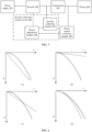
- Q 1( u ) (for example, a quadratic power function) is used as a fitting function of the inverter reactive power adjustment amount about the amplitude value of the output voltage, so that the inverter reactive power adjustment amount may be prevented from being excessively small in linear fitting when the difference between the amplitude value of the output voltage and the amplitude value of the target output voltage is large due to an excessively small linear fitting coefficient, and the inverter reactive power adjustment amount may also be prevented from being excessively large in linear fitting when the difference between the amplitude value of the output voltage and the amplitude value of the target output voltage is small due to an excessively large linear fitting coefficient.
- Q 2( u ) is a function of the power station reactive power adjustment amount about the amplitude value of the grid connection voltage
- d 2 Q 2( u )/ du 2 is a second derivative of the power station reactive power adjustment amount about the amplitude value of the grid connection voltage
- P 2( f ) is a function of the power station active power adjustment amount about the frequency of the grid connection voltage
- d 2 P 2( f )/ df 2 is a second derivative of the power station active power adjustment amount about the frequency of the grid connection voltage.
- a larger difference between the amplitude value of the grid connection voltage and an amplitude value of a target grid connection voltage indicates a larger corresponding power station reactive power adjustment amount.
- the power station reactive power adjustment amount is not simply linearly related to the amplitude value of the grid connection voltage.
- a growth rate of the corresponding power station reactive power adjustment amount is greater than a growth rate of the difference between the amplitude value of the grid connection voltage and the amplitude value of the target grid connection voltage.
- the inverter collection control circuit may obtain the target adjustment amount of the output power of the inverter jointly based on the power station power adjustment signal output by the power station collection module and the inverter power adjustment signal output by the inverter collection control circuit, and may control the inverter to output the target output power.
- the power station collection module may determine the reactive power adjustment amount and the active power adjustment amount of the power station power respectively based on the amplitude value and the frequency of the grid connection voltage of the grid connection point, to further output the reactive power adjustment amount and the active power adjustment amount of the power station power as the power station power adjustment signal to a power adjustment module in the inverter collection circuit.
- the power station power adjustment signal may include the amplitude value and the frequency of the grid connection voltage.
- the obtaining a power station power adjustment signal based on the amplitude value and the frequency of the grid connection voltage may include:
- the power station collection module obtains the amplitude value and the frequency of the grid connection voltage at the grid connection point, and outputs the amplitude value and the frequency of the grid connection voltage at the grid connection point to the inverter collection control circuit.
- the system may output the amplitude value and the frequency of the grid connection voltage at the grid connection point to the inverter collection control circuit by using the inverter collection control circuit, and the inverter collection control circuit determines the adjustment amount of the power station based on the amplitude value and the frequency of the grid connection voltage.
- the method may include: obtaining a power station reactive power adjustment amount based on the amplitude value of the grid connection voltage, obtaining a power station active power adjustment amount based on the frequency of the grid connection voltage, and outputting the power station reactive power adjustment amount and the power station active power adjustment amount.
- the inverter collection control circuit may determine a reactive power adjustment amount and an active power adjustment amount of the power station power respectively based on the amplitude value and the frequency of the grid connection voltage of the grid connection point, to further output the reactive power adjustment amount and the active power adjustment amount of the power station power as the power station power adjustment signal.
- the inverter collection control circuit may obtain a target reactive power adjustment amount of the output power of the inverter jointly based on the power station reactive power adjustment amount and the inverter reactive power adjustment amount, and may also obtain a target active power adjustment amount of the output power of the inverter jointly based on the power station useful power adjustment amount and the inverter active power adjustment amount, and may control the inverter to output the target output power (herein, the target output power may include a target reactive power and a target active power).
- the target output power may include a target reactive power and a target active power.
- a structure is simple.
- the inverter collection control circuit may control the inverter to separately output the target reactive power and/or the target active power. This improves control precision and adjustment efficiency, reduces control time, and reduces control costs.
- the generating an output power adjustment signal based on the power station power adjustment signal and the inverter power adjustment signal, and controlling, by using the output power adjustment signal, the output power of the inverter to be the target output power may include: obtaining an output reactive power adjustment amount based on the power station reactive power adjustment amount and the inverter reactive power adjustment amount, obtaining an output active power adjustment amount based on the power station active power adjustment amount and the inverter active power adjustment amount, and generating the output power adjustment signal based on the output reactive power adjustment amount and the output active power adjustment amount.
- the inverter is controlled, by using the output power adjustment signal, to output the target output power.
- the inverter collection control circuit may obtain the output reactive power adjustment amount (that is, the target reactive power adjustment amount of the output power of the inverter) based on the power station reactive power adjustment amount and the inverter reactive power adjustment amount, and may also obtain the output active power adjustment amount (that is, the target active power adjustment amount of the output power of the inverter) based on the power station useful power adjustment amount and the inverter active power adjustment amount, and generate the output power adjustment signal (for example, a pulse width modulation signal or another control signal that may control the output power of the inverter) based on the output reactive power adjustment amount and the output active power adjustment amount.
- the output reactive power adjustment amount that is, the target reactive power adjustment amount of the output power of the inverter
- the output active power adjustment amount that is, the target active power adjustment amount of the output power of the inverter
- the output power adjustment signal for example, a pulse width modulation signal or another control signal that may control the output power of the inverter
- the inverter reactive power adjustment amount and the inverter active power adjustment amount satisfy: d 2 Q 1 u / du 2 ⁇ 0 d 2 P 1 f / df 2 ⁇ 0
- Q 1( u ) is a function of the inverter reactive power adjustment amount about the amplitude value of the output voltage
- d 2 Q 1( u )/ du 2 is a second derivative of the inverter reactive power adjustment amount about the amplitude value of the output voltage
- P 1( f ) is a function of the inverter active power adjustment amount about the frequency of the output voltage
- d 2 P 1( f )/ df 2 is a second derivative of the inverter active power adjustment amount about the frequency of the output voltage.
- Q 1( u ) (for example, a quadratic power function) is used as a fitting function of the inverter reactive power adjustment amount about the amplitude value of the output voltage, so that the inverter reactive power adjustment amount may be prevented from being excessively small in linear fitting when the difference between the amplitude value of the output voltage and the amplitude value of the target output voltage is large due to an excessively small linear fitting coefficient, and the inverter reactive power adjustment amount may also be prevented from being excessively large in linear fitting when the difference between the amplitude value of the output voltage and the amplitude value of the target output voltage is small due to an excessively large linear fitting coefficient.
- a larger difference between the frequency of the output voltage and a frequency of the target output voltage indicates a larger corresponding inverter active power adjustment amount.
- the inverter active power adjustment amount is not simply linearly related to the frequency of the output voltage.
- a growth rate of the corresponding inverter active power adjustment amount is greater than a growth rate of the difference between the frequency of the output voltage and the frequency of the target output voltage.
- P 1( f ) (for example, a quadratic power function) is used as the function of the inverter active power adjustment amount about the frequency of the output voltage, so that the inverter active power adjustment amount may be prevented from being excessively small in linear fitting when the difference between the frequency of the output voltage and the frequency of the target output voltage is large due to an excessively small linear fitting coefficient, and the inverter active power adjustment amount may also be prevented from being excessively large in linear fitting when the difference between the frequency of the output voltage and the frequency of the target output voltage is small due to an excessively large linear fitting coefficient.
- Q 1( u ) (for example, a quadratic power function) is used as the function of the inverter reactive power adjustment amount about the amplitude value of the output voltage, so that the inverter reactive power adjustment amount may be obtained more accurately based on the amplitude value of the output voltage.
- P 1( f ) (for example, a quadratic power function) is used as the function of the inverter active power adjustment amount about the frequency of the output voltage, so that the inverter active power adjustment amount may be obtained more accurately based on the frequency of the output voltage.
- a method is simple, and control precision and control efficiency are improved.
- the power station reactive power adjustment amount and the inverter active power adjustment amount satisfy: d 2 Q 2 u / du 2 ⁇ 0 d 2 P 2 f / df 2 ⁇ 0
- a larger difference between the amplitude value of the grid connection voltage and an amplitude value of a target grid connection voltage indicates a larger corresponding power station reactive power adjustment amount.
- the power station reactive power adjustment amount is not simply linearly related to the amplitude value of the grid connection voltage.
- a growth rate of the corresponding power station reactive power adjustment amount is greater than a growth rate of the difference between the amplitude value of the grid connection voltage and the amplitude value of the target grid connection voltage.
- Q 2( u ) (for example, a quadratic power function) is used as a fitting function of the power station reactive power adjustment amount about the amplitude value of the grid connection voltage, so that the power station reactive power adjustment amount may be prevented from being excessively small in linear fitting when the difference between the amplitude value of the grid connection voltage and the amplitude value of the target grid connection voltage is large due to an excessively small linear fitting coefficient, and the power station reactive power adjustment amount may also be prevented from being excessively large in linear fitting when the difference between the amplitude value of the grid connection voltage and the amplitude value of the target grid connection voltage is small due to an excessively large linear fitting coefficient.
- a larger difference between the frequency of the grid connection voltage and a frequency of the target grid connection voltage indicates a larger corresponding power station active power adjustment amount.
- the power station active power adjustment amount is not simply linearly related to the frequency of the grid connection voltage.
- a growth rate of the corresponding power station active power adjustment amount is greater than a growth rate of the difference between the frequency of the grid connection voltage and the frequency of the target grid connection voltage.
- P 2( f ) (for example, a quadratic power function) is used as the function of the power station active power adjustment amount about the frequency of the grid connection voltage, so that the power station active power adjustment amount may be prevented from being excessively small in linear fitting when the difference between the frequency of the grid connection voltage and the frequency of the target grid connection voltage is large due to an excessively small linear fitting coefficient, and the power station active power adjustment amount may also be prevented from being excessively large in linear fitting when the difference between the frequency of the grid connection voltage and the frequency of the target grid connection voltage is small due to an excessively large linear fitting coefficient.
- Q 2( u ) (for example, a quadratic power function) is used as the function of the power station reactive power adjustment amount about the amplitude value of the grid connection voltage, so that the power station reactive power adjustment amount may be obtained more accurately based on the amplitude value of the grid connection voltage.
- P 2( f ) (for example, a quadratic power function) is used as the function of the power station active power adjustment amount about the frequency of the grid connection voltage, so that the power station active power adjustment amount may be obtained more accurately based on the frequency of the grid connection voltage.
- a method is simple, and control precision and control efficiency are improved.
- Qout is the output reactive power adjustment amount
- Q1 is the inverter reactive power adjustment amount
- Q2 is the power station reactive power adjustment amount
- k1 is an output reactive power adjustment coefficient
- Pout is the output active power adjustment amount
- P1 is the inverter active power adjustment amount
- P2 is the power station active power adjustment amount
- k2 is an output active power adjustment coefficient
- the system may obtain the output reactive power adjustment amount Qout (that is, the target reactive power adjustment amount of the output power of the inverter) based on the power station reactive power adjustment amount Q1 and the inverter reactive power adjustment amount Q1, and may also obtain the output active power adjustment amount Pout (that is, the target active power adjustment amount of the output power of the inverter) based on the power station useful power adjustment amount P1 and the inverter active power adjustment amount P2, and generate the output power adjustment signal (for example, a pulse width modulation signal or another control signal that may control the output power of the inverter) based on the output reactive power adjustment amount Qout and the output active power adjustment amount Pout.
- This improves control precision and adjustment efficiency, reduces control time, and reduces control costs.
- the power supply system provided in this application may be applicable to a power supply system with different power generation apparatuses, such as a photovoltaic power supply system, a wind energy power supply system, a thermal power supply system, a nuclear energy power supply system, a chemical power supply system, or a biomass energy power supply system. This may be specifically determined based on an actual application scenario, and is not limited herein.
- the power supply system provided in this application may adapt to different application scenarios, for example, an application scenario in which a load in a solar storage power supply environment is powered, an application scenario in which a load in a wind storage power supply environment is powered, an application scenario in which a load in a pure energy storage power supply environment is powered, or another application scenario.
- the following uses the application scenario in which the load in the pure energy storage power supply environment is powered as an example for description. Details are not described below again.
- FIG. 1 is a schematic diagram of an application scenario of a power supply system according to an embodiment of this application.
- a power supply system 1 includes a power supply 11, an inverter 12, a transformer 13, a power station collection module 14, and an inverter collection control circuit 10.
- the power supply 11 may be connected to the transformer 13 through the inverter 12, the transformer 13 may be connected to a power grid 2 at a grid connection point, one end of the power station collection module 14 may be connected to the grid connection point, the other end of the power station collection module may be connected to a first end of the inverter collection control circuit 10, a second end of the inverter collection control circuit 10 may be connected between the inverter 12 and the transformer 13, and a third end of the inverter collection control circuit 10 may be connected to the inverter 12.
- the power supply 11 may supply power to the power grid 2 by using the inverter 12 and the transformer 13.
- the power supply 11 may alternatively be connected to a load 3 through the inverter 12 and the transformer 13, and supply power to the load 3 by using the inverter 12 and the transformer 13.
- the inverter 12 may convert direct current electric energy provided by the power supply 11 into alternating current electric energy.
- the transformer 13 may increase (or decrease) a voltage of the alternating current electric energy to a voltage value that matches the power grid 2 (or the load 3).
- the power supply 11 may alternatively be used as an energy storage apparatus. When power is not insufficient, the power supply 11 may obtain, by using the inverter 12 and the transformer 13, electric energy provided by the power grid 2 for storage.
- the power supply 11 supplies power to the power grid 2 (or the load 3) by using the inverter 12 and the transformer 13 is merely used as an example for description. Details are not described below again.
- the power supply 11 provided in this application is applicable to an application scenario in which a plurality of types of electric devices are powered, for example, a base station device in a remote area with no mains supply or with poor mains supply is powered, or a battery is powered, or a home device (such as a refrigerator or an air conditioner) is powered. This may be specifically determined based on an actual application scenario, and is not limited herein. It may be further understood that, the power grid 2 in FIG.
- the load 3 herein may include a load (an electric apparatus or a power transmission apparatus) whose voltage and current are in a nonlinear relationship in a running (power supply or power consumption) process, such as a motor or a rectifier device.
- a power generation power may be unstable (for example, a light condition of a photovoltaic power generation station changes).
- a voltage and a frequency of a grid connection point at a connection point between the power supply system 1 and the power grid 2 fluctuate. This may increase a loss of a device or even endanger device safety.
- the inverter collection control circuit 100 may determine an adjustment amount of the inverter power based on the amplitude value and the frequency of the output voltage of the inverter 102, to further obtain the inverter power adjustment signal. Because another functional module or an electric energy element (for example, the transformer 103) exists between an output end of the inverter 102 and the grid connection point, the inverter collection control circuit 100 may obtain a target adjustment amount of the output power of the inverter 102 jointly based on the power station power adjustment signal and the inverter power adjustment signal, and may control the inverter 102 to output the target output power.
- another functional module or an electric energy element for example, the transformer 103
- an inverter collection control circuit may include an inverter collection module and a power adjustment module.
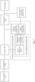
- FIG. 3 is another schematic diagram of a structure of a power supply system according to an embodiment of this application.
- an inverter collection control circuit 200 may include an inverter collection module 205 and a power adjustment module 206.
- a power supply 201 may be connected to a transformer 203 through an inverter 202, the transformer 203 may be connected to a power grid at a grid connection point, one end of a power station collection module 204 may be connected to the grid connection point, the other end of the power station collection module 204 may be connected to a first end of the inverter collection control circuit 200, a second end of the inverter collection control circuit 200 may be connected between the inverter 202 and the transformer 203, and a third end of the inverter collection control circuit 200 may be connected to the inverter 202.
- a first end of the power adjustment module 206 may be used as the first end of the inverter collection control circuit 200 and is connected to the power station collection module 204, one end of the inverter collection module 205 may be used as the second end of the inverter collection control circuit 200 and is connected between the inverter 202 and the transformer 203, the other end of the inverter collection module 205 may be connected to a second end of the power adjustment module 206, and a third end of the power adjustment module 206 may be used as the third end of the inverter collection control circuit 200 and is connected to the inverter 202.
- the inverter collection module 205 may determine the reactive power adjustment amount and the active power adjustment amount of the inverter power respectively based on the amplitude value and the frequency of the output voltage of the inverter 202, to further obtain the inverter power adjustment signal.
- the power adjustment module 206 may obtain a target adjustment amount of the output power of the inverter 202 jointly based on the power station power adjustment signal output by the power station collection module 204 and the inverter power adjustment signal output by the inverter collection control circuit 200, and may control the inverter 202 to output the target output power.
- the inverter collection module 205 may determine the reactive power adjustment amount and the active power adjustment amount of the inverter power respectively based on the amplitude value and the frequency of the output voltage of the inverter 202, to further obtain the inverter power adjustment signal.
- the power adjustment module 206 may obtain the target adjustment amount of the output power of the inverter 202 jointly based on the power station power adjustment signal output by the power station collection module 204 and the inverter power adjustment signal output by the inverter collection control circuit 200, and may control the inverter 202 to output the target output power.
- a structure is simple.
- the system may separately control a reactive power and an active power of the inverter 202. This improves control precision and adjustment efficiency, reduces control time, and reduces control costs.
- the power station power adjustment signal may include a power station reactive power adjustment amount and a power station active power adjustment amount.
- the power station collection module 204 herein may be further configured to obtain the power station reactive power adjustment amount based on an amplitude value of a grid connection voltage, obtain the power station active power adjustment amount based on a frequency of the grid connection voltage, and output the power station reactive power adjustment amount and the power station active power adjustment amount to the inverter collection control circuit 200.
- the power station collection module 204 may determine the reactive power adjustment amount and the active power adjustment amount of the power station power respectively based on the amplitude value and the frequency of the grid connection voltage at the grid connection point, to further output the power station reactive power adjustment amount and the power station active power adjustment amount to the inverter collection circuit.
- the power station collection module 204 may determine the reactive power adjustment amount and the active power adjustment amount of the power station power respectively based on the amplitude value and the frequency of the grid connection voltage of the grid connection point, to further output the reactive power adjustment amount and the active power adjustment amount of the power station power as the power station power adjustment signal to the power adjustment module 206 in the inverter collection circuit.
- the power adjustment module 206 may obtain a target reactive power adjustment amount of the output power of the inverter 202 based on the power station reactive power adjustment amount and the inverter reactive power adjustment amount, and may also obtain a target active power adjustment amount of the output power of the inverter 202 based on the power station useful power adjustment amount and the inverter active power adjustment amount, and may control the inverter 202 to output the target output power (herein, the target output power may include a target reactive power and a target active power).
- the target output power may include a target reactive power and a target active power.
- a structure is simple.
- the system may control the inverter 202 to separately output the target reactive power and/or the target active power. This improves control precision and adjustment efficiency, reduces control time, and reduces control costs.
- Q2(u) (for example, a quadratic power function) is used as a fitting function of the power station reactive power adjustment amount about the amplitude value of the grid connection voltage, so that the power station reactive power adjustment amount may be prevented from being excessively small in linear fitting when the difference between the amplitude value of the grid connection voltage and the amplitude value of the target grid connection voltage is large due to an excessively small linear fitting coefficient, and the power station reactive power adjustment amount may also be prevented from being excessively large in linear fitting when the difference between the amplitude value of the grid connection voltage and the amplitude value of the target grid connection voltage is small due to an excessively large linear fitting coefficient.
- the system may output the amplitude value and the frequency of the grid connection voltage at the grid connection point to the inverter collection control circuit 200 by using the inverter collection control circuit 200, and the inverter collection control circuit 200 determines the adjustment amount of the power station based on the amplitude value and the frequency of the grid connection voltage.
- a method is simple and flexible, has high applicability, and enriches application scenarios and an application scope of the system.
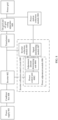
- a first end of a power adjustment module 406 may be used as the first end of the inverter collection control circuit 400 and is connected to the power station collection module 404
- one end of an inverter collection module 405 may be used as the second end of the inverter collection control circuit 400 and is connected between the inverter 402 and the transformer 403
- the other end of the inverter collection module 405 may be connected to a second end of the power adjustment module 406
- a third end of the power adjustment module 406 may be used as the third end of the inverter collection control circuit 400 and is connected to the inverter 402.
- the first end of the power adjustment module 406 may be connected to the power station collection module 404 through a signal determining module 407.
- the inverter reactive power adjustment amount and the inverter active power adjustment amount satisfy the following formulas: d 2 Q 1 u / du 2 ⁇ 0 d 2 P 1 f / df 2 ⁇ 0
- Q 1( u ) (for example, a quadratic power function) is used as a fitting function of the inverter reactive power adjustment amount about the amplitude value of the output voltage, so that the inverter reactive power adjustment amount may be prevented from being excessively small in linear fitting when the difference between the amplitude value of the output voltage and the amplitude value of the target output voltage is large due to an excessively small linear fitting coefficient, and the inverter reactive power adjustment amount may also be prevented from being excessively large in linear fitting when the difference between the amplitude value of the output voltage and the amplitude value of the target output voltage is small due to an excessively large linear fitting coefficient.
- Q 1( u ) (for example, a quadratic power function) is used as the function of the inverter reactive power adjustment amount about the amplitude value of the output voltage, so that the inverter reactive power adjustment amount may be obtained more accurately based on the amplitude value of the output voltage.
- P 1( f ) (for example, a quadratic power function) is used as the function of the inverter active power adjustment amount about the frequency of the output voltage, so that the inverter active power adjustment amount may be obtained more accurately based on the frequency of the output voltage.
- a method is simple, and control precision and control efficiency are improved.
- a larger difference between the amplitude value of the grid connection voltage and an amplitude value of a target grid connection voltage indicates a larger corresponding power station reactive power adjustment amount.
- the power station reactive power adjustment amount is not simply linearly related to the amplitude value of the grid connection voltage.
- a growth rate of the corresponding power station reactive power adjustment amount is greater than a growth rate of the difference between the amplitude value of the grid connection voltage and the amplitude value of the target grid connection voltage.
Landscapes
- Engineering & Computer Science (AREA)
- Power Engineering (AREA)
- Inverter Devices (AREA)
Applications Claiming Priority (2)
| Application Number | Priority Date | Filing Date | Title |
|---|---|---|---|
| CN202210887844.7A CN115313479A (zh) | 2022-07-26 | 2022-07-26 | 供电系统及并网控制方法 |
| PCT/CN2023/100649 WO2024021920A1 (zh) | 2022-07-26 | 2023-06-16 | 供电系统及并网控制方法 |
Publications (2)
| Publication Number | Publication Date |
|---|---|
| EP4395103A1 true EP4395103A1 (de) | 2024-07-03 |
| EP4395103A4 EP4395103A4 (de) | 2025-01-29 |
Family
ID=83858360
Family Applications (1)
| Application Number | Title | Priority Date | Filing Date |
|---|---|---|---|
| EP23845133.0A Pending EP4395103A4 (de) | 2022-07-26 | 2023-06-16 | Stromversorgungssystem und netzgekoppeltes steuerungsverfahren |
Country Status (4)
| Country | Link |
|---|---|
| US (1) | US12438371B2 (de) |
| EP (1) | EP4395103A4 (de) |
| CN (1) | CN115313479A (de) |
| WO (1) | WO2024021920A1 (de) |
Families Citing this family (4)
| Publication number | Priority date | Publication date | Assignee | Title |
|---|---|---|---|---|
| CN115313479A (zh) | 2022-07-26 | 2022-11-08 | 华为数字能源技术有限公司 | 供电系统及并网控制方法 |
| CN118214061B (zh) * | 2022-12-09 | 2026-02-13 | 比亚迪股份有限公司 | 逆变器的控制方法、控制器和逆变器系统 |
| CN118554482B (zh) * | 2024-05-27 | 2025-01-28 | 北京慧碳众和资源科技有限公司 | 用锂电池储能装置充放电进行电网的一次调频方法及系统 |
| CN118381060B (zh) * | 2024-06-26 | 2024-09-24 | 上海思格源智能科技有限公司 | 并网点电压频率的控制方法及装置、供电系统 |
Family Cites Families (12)
| Publication number | Priority date | Publication date | Assignee | Title |
|---|---|---|---|---|
| US8068352B2 (en) * | 2008-12-19 | 2011-11-29 | Caterpillar Inc. | Power inverter control for grid-tie transition |
| JP6084863B2 (ja) * | 2013-02-28 | 2017-02-22 | 川崎重工業株式会社 | 系統連系する電力変換装置 |
| CN103683324B (zh) * | 2013-12-04 | 2016-08-24 | 浙江大学 | 一种微型电网系统中用于分布式电源并联运行模式的基于通信网络的改进的下垂控制方法 |
| CN103997042B (zh) * | 2014-05-15 | 2017-01-04 | 华为技术有限公司 | 电压调节方法、逆变器及微电网系统 |
| CN105162172B (zh) * | 2015-08-13 | 2018-07-20 | 中国电力科学研究院 | 一种并网光伏发电站功率自动控制系统 |
| CN106941257A (zh) * | 2016-01-05 | 2017-07-11 | 许昌学院 | 一种并网逆变器补偿控制方法 |
| CN109742794B (zh) * | 2018-12-29 | 2020-09-01 | 北京四方继保自动化股份有限公司 | 一种分布式光伏发电并网防逆流控制器及控制方法 |
| CN110176790B (zh) * | 2019-05-29 | 2020-12-22 | 王阳 | 具有快速频率响应的新能源发电站的功率控制方法和系统 |
| CN110783953B (zh) * | 2019-10-31 | 2023-11-14 | 特变电工西安电气科技有限公司 | 一种组串式逆变器光伏电站快速调频响应通信方法 |
| US12261549B2 (en) * | 2020-08-25 | 2025-03-25 | Tmeic Corporation | Control device for applying a power conversion device and power conversion system to control an amplitude and a frequency of a voltage |
| CN112421694B (zh) * | 2020-11-13 | 2024-08-13 | 阳光电源股份有限公司 | 新能源发电的一次调频方法及装置 |
| CN115313479A (zh) * | 2022-07-26 | 2022-11-08 | 华为数字能源技术有限公司 | 供电系统及并网控制方法 |
-
2022
- 2022-07-26 CN CN202210887844.7A patent/CN115313479A/zh active Pending
-
2023
- 2023-06-16 EP EP23845133.0A patent/EP4395103A4/de active Pending
- 2023-06-16 WO PCT/CN2023/100649 patent/WO2024021920A1/zh not_active Ceased
-
2024
- 2024-04-03 US US18/625,478 patent/US12438371B2/en active Active
Also Published As
| Publication number | Publication date |
|---|---|
| CN115313479A (zh) | 2022-11-08 |
| WO2024021920A1 (zh) | 2024-02-01 |
| US12438371B2 (en) | 2025-10-07 |
| EP4395103A4 (de) | 2025-01-29 |
| US20240250534A1 (en) | 2024-07-25 |
Similar Documents
| Publication | Publication Date | Title |
|---|---|---|
| EP4395103A1 (de) | Stromversorgungssystem und netzgekoppeltes steuerungsverfahren | |
| US10651724B2 (en) | Systems and methods for increasing output current quality, output power, and reliability of grid-interactive inverters | |
| US11509262B2 (en) | Photovoltaic power generation virtual inertia compensation system and method based on super capacitor energy storage | |
| AU2022203915B2 (en) | Systems and methods of DC Power Conversion and Transmission for Solar Fields | |
| EP4362265B1 (de) | Netzgekoppelter photovoltaikwechselrichter und netzgekoppeltes steuerungsverfahren | |
| EP4312331A2 (de) | Stromversorgungssystem und netzgekoppeltes steuerungsverfahren | |
| EP2463997B1 (de) | System und Verfahren zur Steuerung eines am Netz angeschlossenen Stromerzeugungssystems | |
| EP4432545A1 (de) | Wechselrichter und steuerungsverfahren dafür | |
| EP4579974A1 (de) | Stromversorgungssystem und steuerungsverfahren dafür | |
| EP2922170B1 (de) | Steuerungsvorrichtung für spannungsquellenumrichter und betriebsverfahren dafür | |
| EP4586442A1 (de) | Netz-kontakt-wechselrichtersystem und verfahren zur unterdrückung von niederfrequenter schwingung | |
| CN104283302A (zh) | 空调器和空调器的供电系统 | |
| EP4465472A1 (de) | Fotovoltaischer wechselrichter und steuerungsverfahren dafür sowie fotovoltaisches system | |
| CN204231007U (zh) | 空调器和空调器的供电系统 | |
| US20230089057A1 (en) | Power conversion device | |
| EP4580030A1 (de) | Fotovoltaischer wechselrichter und steuerungsverfahren dafür | |
| CN117293918A (zh) | 一种基于扰动观察法的光伏板输出电压控制方法 | |
| AU2021103722A4 (en) | A power flow control method for ac-dc hybrid power grid | |
| KR102044226B1 (ko) | 전력 모니터링 기능을 구비한 에너지 저장 장치 | |
| EP4344005B1 (de) | Stromversorgungssystem und stromwandlungsverfahren | |
| US12470065B2 (en) | Power supply system and current conversion method | |
| CN116565869B (zh) | 谐波补偿系统、方法及光伏逆变器、存储介质、芯片 | |
| CN115296517A (zh) | 供电系统及其供电方法 | |
| Doe | Control and Operation of Power Converters in High-Voltage Power Systems | |
| Devaki et al. | Modeling of UPQC with hybrid systems for power quality improvemet |
Legal Events
| Date | Code | Title | Description |
|---|---|---|---|
| STAA | Information on the status of an ep patent application or granted ep patent |
Free format text: STATUS: THE INTERNATIONAL PUBLICATION HAS BEEN MADE |
|
| PUAI | Public reference made under article 153(3) epc to a published international application that has entered the european phase |
Free format text: ORIGINAL CODE: 0009012 |
|
| STAA | Information on the status of an ep patent application or granted ep patent |
Free format text: STATUS: REQUEST FOR EXAMINATION WAS MADE |
|
| 17P | Request for examination filed |
Effective date: 20240328 |
|
| AK | Designated contracting states |
Kind code of ref document: A1 Designated state(s): AL AT BE BG CH CY CZ DE DK EE ES FI FR GB GR HR HU IE IS IT LI LT LU LV MC ME MK MT NL NO PL PT RO RS SE SI SK SM TR |
|
| A4 | Supplementary search report drawn up and despatched |
Effective date: 20250108 |
|
| RIC1 | Information provided on ipc code assigned before grant |
Ipc: H02J 3/50 20060101ALI20241223BHEP Ipc: H02J 3/48 20060101ALI20241223BHEP Ipc: H02M 7/42 20060101ALI20241223BHEP Ipc: H02J 3/38 20060101AFI20241223BHEP |
|
| DAV | Request for validation of the european patent (deleted) | ||
| DAX | Request for extension of the european patent (deleted) |