EP4395089A1 - Surge protective device module - Google Patents
Surge protective device module Download PDFInfo
- Publication number
- EP4395089A1 EP4395089A1 EP23214627.4A EP23214627A EP4395089A1 EP 4395089 A1 EP4395089 A1 EP 4395089A1 EP 23214627 A EP23214627 A EP 23214627A EP 4395089 A1 EP4395089 A1 EP 4395089A1
- Authority
- EP
- European Patent Office
- Prior art keywords
- busbar
- spd module
- spd
- module
- terminal
- Prior art date
- Legal status (The legal status is an assumption and is not a legal conclusion. Google has not performed a legal analysis and makes no representation as to the accuracy of the status listed.)
- Pending
Links
Images



Classifications
-
- H—ELECTRICITY
- H01—ELECTRIC ELEMENTS
- H01T—SPARK GAPS; OVERVOLTAGE ARRESTERS USING SPARK GAPS; SPARKING PLUGS; CORONA DEVICES; GENERATING IONS TO BE INTRODUCED INTO NON-ENCLOSED GASES
- H01T4/00—Overvoltage arresters using spark gaps
- H01T4/06—Mounting arrangements for a plurality of overvoltage arresters
-
- H—ELECTRICITY
- H01—ELECTRIC ELEMENTS
- H01C—RESISTORS
- H01C7/00—Non-adjustable resistors formed as one or more layers or coatings; Non-adjustable resistors made from powdered conducting material or powdered semi-conducting material with or without insulating material
- H01C7/10—Non-adjustable resistors formed as one or more layers or coatings; Non-adjustable resistors made from powdered conducting material or powdered semi-conducting material with or without insulating material voltage responsive, i.e. varistors
- H01C7/12—Overvoltage protection resistors; Arresters
-
- H—ELECTRICITY
- H01—ELECTRIC ELEMENTS
- H01C—RESISTORS
- H01C7/00—Non-adjustable resistors formed as one or more layers or coatings; Non-adjustable resistors made from powdered conducting material or powdered semi-conducting material with or without insulating material
- H01C7/10—Non-adjustable resistors formed as one or more layers or coatings; Non-adjustable resistors made from powdered conducting material or powdered semi-conducting material with or without insulating material voltage responsive, i.e. varistors
- H01C7/12—Overvoltage protection resistors; Arresters
- H01C7/126—Means for protecting against excessive pressure or for disconnecting in case of failure
-
- H—ELECTRICITY
- H01—ELECTRIC ELEMENTS
- H01H—ELECTRIC SWITCHES; RELAYS; SELECTORS; EMERGENCY PROTECTIVE DEVICES
- H01H37/00—Thermally-actuated switches
- H01H37/74—Switches in which only the opening movement or only the closing movement of a contact is effected by heating or cooling
- H01H37/76—Contact member actuated by melting of fusible material, actuated due to burning of combustible material or due to explosion of explosive material
- H01H37/761—Contact member actuated by melting of fusible material, actuated due to burning of combustible material or due to explosion of explosive material with a fusible element forming part of the switched circuit
- H01H2037/762—Contact member actuated by melting of fusible material, actuated due to burning of combustible material or due to explosion of explosive material with a fusible element forming part of the switched circuit using a spring for opening the circuit when the fusible element melts
-
- H—ELECTRICITY
- H01—ELECTRIC ELEMENTS
- H01T—SPARK GAPS; OVERVOLTAGE ARRESTERS USING SPARK GAPS; SPARKING PLUGS; CORONA DEVICES; GENERATING IONS TO BE INTRODUCED INTO NON-ENCLOSED GASES
- H01T1/00—Details of spark gaps
- H01T1/14—Means structurally associated with spark gap for protecting it against overload or for disconnecting it in case of failure
-
- H—ELECTRICITY
- H02—GENERATION; CONVERSION OR DISTRIBUTION OF ELECTRIC POWER
- H02H—EMERGENCY PROTECTIVE CIRCUIT ARRANGEMENTS
- H02H9/00—Emergency protective circuit arrangements for limiting excess current or voltage without disconnection
- H02H9/04—Emergency protective circuit arrangements for limiting excess current or voltage without disconnection responsive to excess voltage
Definitions
- the present invention relates to surge protective devices.
- the overvoltage clamping element includes a gas discharge tube.
- the busbar terminal contact is substantially U-shaped in lateral cross-section and includes integral legs and a base section that collectively define a busbar receiving slot having a rear facing opening.
- the busbar terminal contact is a spring.
- the SPD module includes an auxiliary protected earth terminal electrically connected to the busbar by the busbar terminal contact when the SPD module is mounted on the busbar.
- the SPD module includes an integral indicator system operative to provide, in response to actuation the thermal disconnector, an alert that the SPD module has failed.
- spatially relative terms such as “under”, “below”, “lower”, “over”, “upper” and the like, may be used herein for ease of description to describe one element or feature's relationship to another element(s) or feature(s) as illustrated in the figures. It will be understood that the spatially relative terms are intended to encompass different orientations of the device in use or operation in addition to the orientation depicted in the figures. For example, if the device in the figures is turned over, elements described as “under” or “beneath” other elements or features would then be oriented “over” the other elements or features. Thus, the exemplary term “under” can encompass both an orientation of over and under. The device may be otherwise oriented (rotated 90 degrees or at other orientations) and the spatially relative descriptors used herein interpreted accordingly.
- a unitary object can be a composition composed of multiple parts or components secured together at joints or seams.
- the module 100 is configured, sized and shaped for mounting on the set BS of busbars B1-B3 , BN , BPE .
- the busbars B1-B3 , BN , BPE are arranged in series such that they extend lengthwise substantially parallel to one another and are laterally spaced apart by gaps 7.
- Each busbar extends lengthwise parallel to a busbar longitudinal axis B-B ( FIG. 1 ).
- the busbars are serially disposed along a busbar lateral axis D-D ( FIG. 1 ).
- the module 100 has a primary axis A-A that extends substantially perpendicular to the longitudinal axis B-B of the busbars B1-B3 , BN , BPE , and a heightwise axis that extends substantially perpendicular to each of the axes A-A and B-B .
- "front” or “distal” refers to the end of the module 100 farther away from the busbars B1-B3 , BN , BPE when the module 100 is mounted on the busbars B1-B3 , BN , BPE
- "rear” or "proximal” refers to the end of the module 100 nearer the busbars B1-B3 , BN , BPE.
- the electrical contact terminal assemblies C1 , C2 , C3 , CN , CPE may each be constructed and operate in the same manner.
- the terminal assembly C3 will be described in greater detail hereinbelow. However, it will be appreciated that this description likewise applies to the terminal assemblies C1 , C2 , CN , CPE .
- the three-phase surge protective (SP) circuit 131 includes a protected earth gas discharge tube (PE GDT) 132 , a first line SPD assembly S1 , a second line SPD assembly S2 , a third line SPD assembly S3 , and a neutral bridge conductor 134.
- the SPD assemblies S1-S3 each include a first terminal 142 , a second terminal 144 , and one or more overvoltage clamping elements 145 electrically connected between the terminals 142 and 144.
- the overvoltage clamping element(s) 145 may include a varistor (e.g., a metal-oxide varistor (MOV)) and/or a gas discharge tube (GDT).
- a varistor e.g., a metal-oxide varistor (MOV)
- GDT gas discharge tube
- Each first terminal 142 is electrically connected to a respective one of the contact terminal assemblies C1 , C2 , C3 by an electrically conductive bridge member 148 and the corresponding bridge portion 173.
- the integral terminal connection system 161 includes the busbar terminal assemblies C1 , C2 , C3 , CN , CPE and five electrical connection assemblies E1 , E2 , E3 , EN , EPE.
- the line SPD assemblies S1, S2, S3, the neutral bridge conductor member 134 , and the PE auxiliary terminal 186 are each electrically connected to their respective busbars B1 , B2 , B3 , BN and BPE via the busbar terminal assemblies C1 , C2 , C3 , CN , and CPE , respectively.
- the feed cables T1 , T2 , T3 , TN , and TPE are each electrically connected to their respective busbars B1 , B2 , B3 , BN and BPE via the busbar terminal assemblies C1 , C2 , C3 , CN , and CPE , respectively.
Landscapes
- Engineering & Computer Science (AREA)
- Microelectronics & Electronic Packaging (AREA)
- Physics & Mathematics (AREA)
- Electromagnetism (AREA)
- Emergency Protection Circuit Devices (AREA)
Abstract
Description
- The present application claims the benefit of and priority from
U.S. Provisional Patent Application No. 63/477,389, filed December 28, 2022 - The present invention relates to surge protective devices.
- Frequently, excessive voltage or current is applied across service lines that deliver power to residences and commercial and institutional facilities. Such excess voltage or current spikes (transient overvoltages and surge currents) may result from lightning strikes, for example. The above events may be of particular concern in telecommunications distribution centers, hospitals and other facilities where equipment damage caused by overvoltages and/or current surges is not acceptable and resulting down time may be very costly.
- Typically, sensitive electronic equipment may be protected against transient overvoltages and surge currents using surge protective devices (SPDs). For example, an overvoltage protection device may be installed at a power input of equipment to be protected, which is typically protected against overcurrents when it fails. Typical failure mode of an SPD is a short circuit. The overcurrent protection typically employed is a combination of an internal thermal disconnector to protect the device from overheating due to increased leakage currents and an external fuse to protect the device from higher fault currents. Different SPD technologies may avoid the use of the internal thermal disconnector because, in the event of failure, they change their operation mode to a low ohmic resistance.
- In the event of a surge current in a line L (e.g., a voltage line of a three-phase electrical power circuit), protection of power system load devices may necessitate providing a current path to ground for the excess current of the surge current. The surge current may generate a transient overvoltage between the line L and the neutral line N (the neutral line N may be conductively coupled to an earth ground PE). Since the transient overvoltage significantly exceeds the operating voltage of the SPD, the SPD will become conductive, allowing the excess current to flow from line L through SPD to the neutral N. Once the surge current has been conducted to neutral N, the overvoltage condition ends and the SPD may become non-conducting again. However, in some cases, one or more SPDs may begin to allow a leakage current to be conducted even at voltages that are lower that the operating voltage of the SPDs. Such conditions may occur in the case of an SPD deteriorating.
- Terminal blocks are commonly used to terminate and connect an electrical cable to a circuit or other electrical system via a busbar system.
- According to some embodiments, a surge protective device (SPD) module for mounting on a busbar includes a busbar terminal contact, an overvoltage clamping element and a feed terminal. The busbar terminal contact is configured to electrically connect the SPD module to the busbar. The feed terminal is configured to electrically connect a feed cable to the SPD module. The overvoltage clamping element and the feed terminal are both electrically connected to the busbar by the busbar terminal contact when the SPD module is mounted on the busbar.
- According to some embodiments, the SPD module includes: a plurality of busbar terminal contacts, wherein each of the busbar terminal contacts is configured to receive and electrically connect the SPD module to a respective one of a plurality of busbars; a plurality of overvoltage clamping elements; and a plurality of feed terminals, wherein each of the feed terminals is configured to electrically connect a respective one of the feed cables to the SPD module. Each of the overvoltage clamping elements shares a respective one of the busbar terminal contacts with a respective one of the feed terminals to effect electrical connection with a corresponding one of the busbars when the SPD module is mounted on the busbars.
- According to some embodiments, the overvoltage clamping element includes a varistor.
- According to some embodiments, the SPD module further includes a gas discharge tube electrically connecting the varistor to the busbar terminal contact.
- In some embodiments, the overvoltage clamping element includes a gas discharge tube.
- In some embodiments, the feed terminal is a cable clamp connector.
- According to some embodiments, the cable clamp connector is a spring clamp connector configured to receive and capture an end of the feed cable.
- According to some embodiments, the SPD module includes a contact terminal assembly including the busbar terminal contact and a supplemental spring mounted on the busbar terminal contact.
- According to some embodiments, the busbar terminal contact is substantially U-shaped in lateral cross-section and includes integral legs and a base section that collectively define a busbar receiving slot having a rear facing opening.
- In some embodiments, the busbar terminal contact is a spring.
- According to some embodiments, the SPD module includes a module housing defining a chamber containing the overvoltage clamping element.
- In some embodiments, the SPD module includes an auxiliary protected earth terminal electrically connected to the busbar by the busbar terminal contact when the SPD module is mounted on the busbar.
- According to some embodiments, the SPD module includes a thermal disconnector responsive to overheating of the overvoltage clamping element to disconnect the overvoltage clamping element.
- In some embodiments, the SPD module includes an integral indicator system operative to provide, in response to actuation the thermal disconnector, an alert that the SPD module has failed.
- According to some embodiments, the SPD module includes an auxiliary power output connector connected to the busbar terminal contact and the feed terminal.
- In some embodiments, the auxiliary power output connector is provided with an inline fuse.
- According to some embodiments, the SPD module includes a mounting system including a spring-loaded locking member to secure the SPD module to the busbar.
- According to some embodiments, an electrical power supply system includes a busbar, a feed cable, and a surge protective device (SPD) module mounted on the busbar. The SPD module includes: a busbar terminal contact engaging and electrically connecting the SPD module to the busbar; an overvoltage clamping element; and a feed terminal configured to electrically connect a feed cable to the SPD module. The overvoltage clamping element and the feed terminal are both electrically connected to the busbar by the busbar terminal contact. The feed cable is connected to the SPD module at the feed terminal and feeds electrical power to the busbar through the SPD module.
-
-
FIG. 1 is a front view of an electrical power system including a surge protective device (SPD) module in accordance with some embodiments. -
FIG. 2 is a side view of the SPD module ofFIG. 1 . -
FIG. 3 is a front perspective view of the SPD module ofFIG. 1 . -
FIG. 4 is a rear view of the SPD module ofFIG. 1 . -
FIG. 5 is a fragmentary, rear perspective view of the SPD module ofFIG. 1 . -
FIG. 6 is a fragmentary, front perspective view of the SPD module ofFIG. 1 . -
FIG. 7 is an enlarged, fragmentary, rear perspective view of the SPD module ofFIG. 1 . -
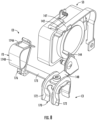
FIG. 8 is an enlarged, fragmentary, front perspective view of the SPD module ofFIG. 1 . -
FIG. 9 is a schematic view of an electrical circuit including the SPD module ofFIG. 1 , a set of busbars, and a set of feed cables. - The present invention now will be described more fully hereinafter with reference to the accompanying drawings, in which illustrative embodiments of the invention are shown. In the drawings, the relative sizes of regions or features may be exaggerated for clarity. This invention may, however, be embodied in many different forms and should not be construed as limited to the embodiments set forth herein; rather, these embodiments are provided so that this disclosure will be thorough and complete, and will fully convey the scope of the invention to those skilled in the art.
- It will be understood that when an element is referred to as being "coupled" or "connected" to another element, it can be directly coupled or connected to the other element or intervening elements may also be present. In contrast, when an element is referred to as being "directly coupled" or "directly connected" to another element, there are no intervening elements present. Like numbers refer to like elements throughout.
- In addition, spatially relative terms, such as "under", "below", "lower", "over", "upper" and the like, may be used herein for ease of description to describe one element or feature's relationship to another element(s) or feature(s) as illustrated in the figures. It will be understood that the spatially relative terms are intended to encompass different orientations of the device in use or operation in addition to the orientation depicted in the figures. For example, if the device in the figures is turned over, elements described as "under" or "beneath" other elements or features would then be oriented "over" the other elements or features. Thus, the exemplary term "under" can encompass both an orientation of over and under. The device may be otherwise oriented (rotated 90 degrees or at other orientations) and the spatially relative descriptors used herein interpreted accordingly.
- Well-known functions or constructions may not be described in detail for brevity and/or clarity.
- As used herein the expression "and/or" includes any and all combinations of one or more of the associated listed items.
- The terminology used herein is for the purpose of describing particular embodiments only and is not intended to be limiting of the invention. As used herein, the singular forms "a", "an" and "the" are intended to include the plural forms as well, unless the context clearly indicates otherwise. It will be further understood that the terms "comprises" and/or "comprising," when used in this specification, specify the presence of stated features, integers, steps, operations, elements, and/or components, but do not preclude the presence or addition of one or more other features, integers, steps, operations, elements, components, and/or groups thereof.
- Unless otherwise defined, all terms (including technical and scientific terms) used herein have the same meaning as commonly understood by one of ordinary skill in the art to which this invention belongs. It will be further understood that terms, such as those defined in commonly used dictionaries, should be interpreted as having a meaning that is consistent with their meaning in the context of the relevant art and will not be interpreted in an idealized or overly formal sense unless expressly so defined herein.
- As used herein, "monolithic" means an object that is a single, unitary piece formed or composed of a material without joints or seams. Alternatively, a unitary object can be a composition composed of multiple parts or components secured together at joints or seams.
- With reference to the figures, a surge protective device (SPD)
module 100 according to embodiments of the present invention are shown therein. TheSPD module 100 may be used in an electricalpower supply system 10. The electricalpower supply system 10 includes a rack orcabinet 62, for example, containing a set BS of five busbars B1, B2, B3, BN and BPE. The electricalpower supply system 10 also includes a set TS of electrically conductive cables T1, T2, T3, TN and TPE. The busbars B1, B2 and B3 are each connected to a respective one of three voltage lines L1, L2 and L3 of a three-phase electrical power supply system. The busbar BN is connected to a neutral line N of the three-phase electrical power supply system. The busbar BPE is connected to a ground or protected earth ground. Each of the three-phase lines may be provided with a main circuit breaker or fuse in or near thecabinet 62, for example. - The
SPD module 100 is mounted on the busbars BS to protectequipment 66 connected to the busbars BS from transient overvoltages and surge currents. TheSPD module 100 can also be used to connect the electrically conductive cables T1, T2, T3, TN and TPE to the busbars B1, B2, B3, BN and BPE, respectively. In some embodiments, the cables T1, T2, T3, TN and TPE are electrical power feed cables (i.e., input power cables). When theSPD module 100 is mounted on the busbars BS and the cables T1, T2, T3, TN and TPE are electrically connected to theSPD module 100 as described herein, the cables T1, T2, T3, TN and TPE feed electrical power to the busbars B1, B2, B3, BN through theSPD module 100. - The
SPD module 100 includes a module housing ormodule housing assembly 110, a mountingsystem 121, a three-phase surge protective (SP)circuit 131, an integralterminal connection system 161, an integral indicator system 181, an auxiliary protected earth (PE)terminal 186, and an auxiliarypower supply terminal 188. Each of these components and systems forms an integral part of theSPD module 100 and is disposed on thehousing 110, as discussed in more detail below. - According to some embodiments and as shown, the
module 100 is configured, sized and shaped for mounting on the set BS of busbars B1-B3, BN, BPE. The busbars B1-B3, BN, BPE are arranged in series such that they extend lengthwise substantially parallel to one another and are laterally spaced apart bygaps 7. Each busbar extends lengthwise parallel to a busbar longitudinal axis B-B (FIG. 1 ). The busbars are serially disposed along a busbar lateral axis D-D (FIG. 1 ). - According to some embodiments and as shown, the
module 100 is removably and replaceably mountable on the busbars B1-B3, BN, BPE. - The
module 100 has a primary axis A-A that extends substantially perpendicular to the longitudinal axis B-B of the busbars B1-B3, BN, BPE, and a heightwise axis that extends substantially perpendicular to each of the axes A-A and B-B. As used herein, "front" or "distal" refers to the end of themodule 100 farther away from the busbars B1-B3, BN, BPE when themodule 100 is mounted on the busbars B1-B3, BN, BPE, and "rear" or "proximal" refers to the end of themodule 100 nearer the busbars B1-B3, BN, BPE. - The
housing 110 may be formed from one or more housing members. Thehousing 110 forms an enclosure that defines and encloses an internal cavity orchamber 118. Thechamber 118 may be partitioned into multiple enclosed chambers. - The
housing 110 may be formed of any suitable electrically insulating material or materials. In some embodiments, each of the housing members is formed of a rigid polymeric material. According to some embodiments, the housing members are formed of an electrically insulating polymeric material. Suitable polymeric materials may include polyamide (PA), polypropylene (PP), polyphenylene sulfide (PPS), polybutylene terephthalate (PBT) or ABS, for example. The polymeric material may be provided with or without glass fiber reinforcement. - The mounting
system 121 includes busbar receiver slots 120 (defined in the housing 110), a spring-loadedlocking member 124, and busbar terminal assemblies C1, C2, C3, CN, CPE (collectively referred to herein as the terminal assemblies C). The busbar terminal assemblies C1, C2, C3, CN, CPE and thebusbar receiver slots 120 are sized and configured to receive the busbars B1-B3, BN, BPE. - The electrical contact terminal assemblies C1, C2, C3, CN, CPE may each be constructed and operate in the same manner. The terminal assembly C3 will be described in greater detail hereinbelow. However, it will be appreciated that this description likewise applies to the terminal assemblies C1, C2, CN, CPE.
- The contact terminal assembly C3 includes a
contact member 170, abridge portion 173, and a pair ofsupplemental springs 172. Thecontact member 170 and thesupplemental springs 172 together form a connector subassembly that is seated in acorresponding busbar slot 120. - The
contact member 170 is a thin sheet that is substantially U-shaped in lateral cross-section. The contact member includes fourintegral legs 170A depending and cantilevered from the side edges of abase section 170B. - The
base section 170B andlegs 170A collectively define a busbar receiving slot 170C having a rear facing opening. In some embodiments, thecontact member 170 is a spring. - The
contact member 170 may be formed of any suitable resilient, electrically conductive material. In some embodiments, thecontact member 170 is formed of metal. In some embodiments, thecontact member 170 is formed of copper or copper alloy. Suitable metal materials may include CuSn6, Cu, or CuSn0.15, for example. In some embodiments, thecontact member 170 is unitary (composite or monolithic) and, in some embodiments, thecontact member 170 is monolithic. In some embodiments, thecontact member 170 is formed (e.g., cut and bent) from sheet metal. - The
bridge portion 173 is electrically conductive and extends laterally from thecontact member 173. In some embodiments (e.g., as illustrated), thebridge portion 173 is integrally formed with thecontact member 170. In some embodiments (e.g., as illustrated), thebridge portion 173 is monolithic with thecontact member 170. - The
bridge portion 173 may be formed of any suitable electrically conductive material. In some embodiments, thebridge portion 173 is formed of metal. In some embodiments, thecontact member 173 is formed of copper or copper alloy. Suitable metal materials may include CuSn6, Cu, or CuSn0.15, for example. - The three-phase surge protective (SP)
circuit 131 includes a protected earth gas discharge tube (PE GDT) 132, a first line SPD assembly S1, a second line SPD assembly S2, a third line SPD assembly S3, and aneutral bridge conductor 134. The SPD assemblies S1-S3 each include afirst terminal 142, asecond terminal 144, and one or moreovervoltage clamping elements 145 electrically connected between theterminals - The overvoltage clamping element(s) 145 may include a varistor (e.g., a metal-oxide varistor (MOV)) and/or a gas discharge tube (GDT).
- Each
second terminal 144 is electrically connected to the terminal assembly CPE via an associatedthermal disconnector 147 and theneutral bridge conductor 134. - Each
first terminal 142 is electrically connected to a respective one of the contact terminal assemblies C1, C2, C3 by an electricallyconductive bridge member 148 and the correspondingbridge portion 173. - The integral
terminal connection system 161 includes the busbar terminal assemblies C1, C2, C3, CN, CPE and five electrical connection assemblies E1, E2, E3, EN, EPE. - Each electrical connection assemblies E1, E2, E3, EN, EPE includes an electrically conductive feed terminal F1, F2, F3, FN, FPE and a
bridge member 176. - Each feed terminal F1, F2, F3, FN, FPE may be a cable clamp connector. Each feed terminal F1, F2, F3, FN, FPE includes an
opening 174A to receive the end of a respective one of the cables T1, T2, T3, TN, TPE, and aspring mechanism 174B to fix or capture the cable T1, T2, T3, TN, TPE therein. However, it will be appreciated that other types and configurations of connectors may be used for the feed terminals F1, F2, F3, FN, FPE to secure and electrically connect the feed cable ends. Thehousing 110 includes anopening 119 at each feed terminal F1, F2, F3, FN, FPE to receive the cable end. - The integral indicator system 181 may include a local alert mechanism 182 and/or a
remote alert mechanism 183. In the illustratedSPD module 100, the local alert mechanism 182 includes adisplaceable indicator member 182A. In the illustratedSPD module 100, theremote alert mechanism 183 includes anRC connector 183A for connecting to a remote monitoring system. - In use, the
SPD module 100 is mounted on the busbars B1, B2, B3, BN and BPE as shown and described such that each of the busbars B1, B2, B3, BN and BPE is received in a respective one of the busbar terminal assemblies C1, C2, C3, CN, and CPE, respectively, thereby making mechanical and electrical contact between the busbars B1, B2, B3, BN and BPE and the busbar terminal assemblies C1, C2, C3, CN, and CPE, respectively. The feed cables T1, T2, T3, TN, and TPE are each inserted one of the feed terminals F1, F2, F3, FN, and FPE, respectively, thereby making mechanical and electrical contact between feed cables T1, T2, T3, TN, and TPE and the feed terminals F1, F2, F3, FN, and FPE, respectively. - In this manner, the line SPD assemblies S1, S2, S3, the neutral
bridge conductor member 134, and the PEauxiliary terminal 186 are each electrically connected to their respective busbars B1, B2, B3, BN and BPE via the busbar terminal assemblies C1, C2, C3, CN, and CPE, respectively. Additionally, in this manner the feed cables T1, T2, T3, TN, and TPE are each electrically connected to their respective busbars B1, B2, B3, BN and BPE via the busbar terminal assemblies C1, C2, C3, CN, and CPE, respectively. - The
thermal disconnectors 147 are responsive to overheating of the overvoltage clamping element to disconnect the overvoltage clamping element. The integral indicator system 181 is operative to provide via the local alert mechanism 182 and theremote alert mechanism 183, in response to actuation of athermal disconnector 147, an alert that theSPD module 100 has failed. - The auxiliary
power output connector 188 is connected to the busbar terminal assemblies C1 and is provided with aninline fuse 188A. -
FIG. 9 is a schematic view representing an electrical circuit including theSPD module 100, the busbars B1, B2, B3, BN and BPE and the feed cables T1, T2, T3, TN, and TPE. - Therefore, it will be appreciated that in accordance with embodiments of the invention there is provided a modular SPD device with an integrated terminal block for a busbar system. The terminal block is integrated with the SPD such that block power feed/input terminals are directly connected to the SPD busbar terminals. That is, the feed terminals and the SPD elements are each internally connected to the same set of busbar contacts. Therefore, the terminal block and SPD elements share a single set of busbar terminals. The SPD device provides combined protections and power connectivity for busbar systems in an integrated module. This arrangement can provide lower cost, reduced complexity, improved handling and convenience, and improved form factor as compared to known solutions.
- Many alterations and modifications may be made by those having ordinary skill in the art, given the benefit of present disclosure, without departing from the spirit and scope of the invention. Therefore, it must be understood that the illustrated embodiments have been set forth only for the purposes of example, and that it should not be taken as limiting the invention as defined by the following claims. The following claims, therefore, are to be read to include not only the combination of elements which are literally set forth but all equivalent elements for performing substantially the same function in substantially the same way to obtain substantially the same result. The claims are thus to be understood to include what is specifically illustrated and described above, what is conceptually equivalent, and also what incorporates the essential idea of the invention.
- Aspects of some exemplary embodiments of the present invention are described in the following clauses:
- 1. A surge protective device (SPD) module for mounting on a busbar, the SPD module comprising:
- a busbar terminal contact configured to electrically connect the SPD module to the busbar;
- an overvoltage clamping element; and
- a feed terminal configured to electrically connect a feed cable to the SPD module;
- wherein the overvoltage clamping element and the feed terminal are both electrically connected to the busbar by the busbar terminal contact when the SPD module is mounted on the busbar.
- 2. The SPD module of
Clause 1 including:- a plurality of busbar terminal contacts, wherein each of the busbar terminal contacts is configured to receive and electrically connect the SPD module to a respective one of a plurality of busbars;
- a plurality of overvoltage clamping elements; and
- a plurality of feed terminals, wherein each of the feed terminals is configured to electrically connect a respective one of the feed cables to the SPD module;
- wherein each of the overvoltage clamping elements shares a respective one of the busbar terminal contacts with a respective one of the feed terminals to effect electrical connection with a corresponding one of the busbars when the SPD module is mounted on the busbars.
- 3. The SPD module of any of the preceding clauses wherein the overvoltage clamping element includes a varistor.
- 4. The SPD module of
Clause 3 further including a gas discharge tube electrically connecting the varistor to the busbar terminal contact. - 5. The SPD module of any of the preceding clauses wherein the overvoltage clamping element includes a gas discharge tube.
- 6. The SPD module of any of the preceding clauses wherein the feed terminal is a cable clamp connector.
- 7. The SPD module of any of the preceding clauses wherein the cable clamp connector is a spring clamp connector configured to receive and capture an end of the feed cable.
- 8. The SPD module of any of the preceding clauses including a contact terminal assembly including the busbar terminal contact and a supplemental spring mounted on the busbar terminal contact.
- 9. The SPD module of any of the preceding clauses wherein the busbar terminal contact is substantially U-shaped in lateral cross-section and includes integral legs and a base section that collectively define a busbar receiving slot having a rear facing opening.
- 10. The SPD module of Clause 9 wherein the busbar terminal contact is a spring.
- 11. The SPD module of any of the preceding clauses including a module housing defining a chamber containing the overvoltage clamping element.
- 12. The SPD module of any of the preceding clauses including an auxiliary protected earth terminal electrically connected to the busbar by the busbar terminal contact when the SPD module is mounted on the busbar.
- 13. The SPD module of any of the preceding clauses including a thermal disconnector responsive to overheating of the overvoltage clamping element to disconnect the overvoltage clamping element.
- 14. The SPD module of Clause 13 including an integral indicator system operative to provide, in response to actuation the thermal disconnector, an alert that the SPD module has failed.
- 15. The SPD module of any of the preceding clauses including an auxiliary power output connector connected to the busbar terminal contact and the feed terminal.
- 16. The SPD module of Clause 15 wherein the auxiliary power output connector is provided with an inline fuse.
- 17. The SPD module of any of the preceding clauses including a mounting system including a spring-loaded locking member to secure the SPD module to the busbar.
- 18. An electrical power supply system comprising:
- a busbar;
- a feed cable; and
- a surge protective device (SPD) module mounted on the busbar, the SPD module comprising:
- a busbar terminal contact engaging and electrically connecting the SPD module to the busbar;
- an overvoltage clamping element; and
- a feed terminal configured to electrically connect a feed cable to the SPD module;
- wherein the overvoltage clamping element and the feed terminal are both electrically connected to the busbar by the busbar terminal contact; and
- wherein the feed cable is connected to the SPD module at the feed terminal and feeds electrical power to the busbar through the SPD module.
Claims (15)
- A surge protective device (SPD) module for mounting on a busbar, the SPD module comprising:a busbar terminal contact configured to electrically connect the SPD module to the busbar;an overvoltage clamping element; anda feed terminal configured to electrically connect a feed cable to the SPD module;wherein the overvoltage clamping element and the feed terminal are both electrically connected to the busbar by the busbar terminal contact when the SPD module is mounted on the busbar.
- The SPD module of Claim 1 including:a plurality of busbar terminal contacts, wherein each of the busbar terminal contacts is configured to receive and electrically connect the SPD module to a respective one of a plurality of busbars;a plurality of overvoltage clamping elements; anda plurality of feed terminals, wherein each of the feed terminals is configured to electrically connect a respective one of the feed cables to the SPD module;wherein each of the overvoltage clamping elements shares a respective one of the busbar terminal contacts with a respective one of the feed terminals to effect electrical connection with a corresponding one of the busbars when the SPD module is mounted on the busbars.
- The SPD module of any of the preceding claims wherein the overvoltage clamping element includes a varistor.
- The SPD module of any of the preceding claims wherein the overvoltage clamping element includes a gas discharge tube.
- The SPD module of any of the preceding claims wherein the feed terminal is a cable clamp connector.
- The SPD module of any of the preceding claims wherein the cable clamp connector is a spring clamp connector configured to receive and capture an end of the feed cable.
- The SPD module of any of the preceding claims including a contact terminal assembly including the busbar terminal contact and a supplemental spring mounted on the busbar terminal contact.
- The SPD module of any of the preceding claims wherein the busbar terminal contact is substantially U-shaped in lateral cross-section and includes integral legs and a base section that collectively define a busbar receiving slot having a rear facing opening.
- The SPD module of any of the preceding claims including a module housing defining a chamber containing the overvoltage clamping element.
- The SPD module of any of the preceding claims including an auxiliary protected earth terminal electrically connected to the busbar by the busbar terminal contact when the SPD module is mounted on the busbar.
- The SPD module of any of the preceding claims including a thermal disconnector responsive to overheating of the overvoltage clamping element to disconnect the overvoltage clamping element.
- The SPD module of Claim 11 including an integral indicator system operative to provide, in response to actuation the thermal disconnector, an alert that the SPD module has failed.
- The SPD module of any of the preceding claims including an auxiliary power output connector connected to the busbar terminal contact and the feed terminal.
- The SPD module of any of the preceding claims including a mounting system including a spring-loaded locking member to secure the SPD module to the busbar.
- An electrical power supply system comprising:a busbar;a feed cable; anda surge protective device (SPD) module mounted on the busbar, the SPD module comprising:a busbar terminal contact engaging and electrically connecting the SPD module to the busbar;an overvoltage clamping element; anda feed terminal configured to electrically connect a feed cable to the SPD module;wherein the overvoltage clamping element and the feed terminal are both electrically connected to the busbar by the busbar terminal contact; andwherein the feed cable is connected to the SPD module at the feed terminal and feeds electrical power to the busbar through the SPD module.
Priority Applications (1)
| Application Number | Priority Date | Filing Date | Title |
|---|---|---|---|
| EP26176982.2A EP4769859A2 (en) | 2022-12-28 | 2023-12-06 | SURGE PROTECTION DEVICE MODULES |
Applications Claiming Priority (1)
| Application Number | Priority Date | Filing Date | Title |
|---|---|---|---|
| US202263477389P | 2022-12-28 | 2022-12-28 |
Related Child Applications (1)
| Application Number | Title | Priority Date | Filing Date |
|---|---|---|---|
| EP26176982.2A Division EP4769859A2 (en) | 2022-12-28 | 2023-12-06 | SURGE PROTECTION DEVICE MODULES |
Publications (1)
| Publication Number | Publication Date |
|---|---|
| EP4395089A1 true EP4395089A1 (en) | 2024-07-03 |
Family
ID=89121917
Family Applications (2)
| Application Number | Title | Priority Date | Filing Date |
|---|---|---|---|
| EP23214627.4A Pending EP4395089A1 (en) | 2022-12-28 | 2023-12-06 | Surge protective device module |
| EP26176982.2A Pending EP4769859A2 (en) | 2022-12-28 | 2023-12-06 | SURGE PROTECTION DEVICE MODULES |
Family Applications After (1)
| Application Number | Title | Priority Date | Filing Date |
|---|---|---|---|
| EP26176982.2A Pending EP4769859A2 (en) | 2022-12-28 | 2023-12-06 | SURGE PROTECTION DEVICE MODULES |
Country Status (2)
| Country | Link |
|---|---|
| EP (2) | EP4395089A1 (en) |
| DE (1) | DE202023107226U1 (en) |
Citations (4)
| Publication number | Priority date | Publication date | Assignee | Title |
|---|---|---|---|---|
| DE202018104832U1 (en) * | 2018-06-22 | 2018-09-07 | Dehn + Söhne Gmbh + Co. Kg | Surge arrester arrangement for the protection of low-voltage supply systems |
| DE202019102722U1 (en) * | 2018-12-21 | 2019-08-28 | Raycap Ip Development Ltd. | Surge protection device modules |
| EP3713022A1 (en) * | 2019-03-18 | 2020-09-23 | DEHN SE + Co KG | Electrical surge protection element |
| DE202022104057U1 (en) * | 2022-07-19 | 2022-08-12 | Phoenix Contact Gmbh & Co. Kg | Electrical surge protection device |
-
2023
- 2023-12-06 DE DE202023107226.7U patent/DE202023107226U1/en active Active
- 2023-12-06 EP EP23214627.4A patent/EP4395089A1/en active Pending
- 2023-12-06 EP EP26176982.2A patent/EP4769859A2/en active Pending
Patent Citations (4)
| Publication number | Priority date | Publication date | Assignee | Title |
|---|---|---|---|---|
| DE202018104832U1 (en) * | 2018-06-22 | 2018-09-07 | Dehn + Söhne Gmbh + Co. Kg | Surge arrester arrangement for the protection of low-voltage supply systems |
| DE202019102722U1 (en) * | 2018-12-21 | 2019-08-28 | Raycap Ip Development Ltd. | Surge protection device modules |
| EP3713022A1 (en) * | 2019-03-18 | 2020-09-23 | DEHN SE + Co KG | Electrical surge protection element |
| DE202022104057U1 (en) * | 2022-07-19 | 2022-08-12 | Phoenix Contact Gmbh & Co. Kg | Electrical surge protection device |
Also Published As
| Publication number | Publication date |
|---|---|
| EP4769859A2 (en) | 2026-07-01 |
| DE202023107226U1 (en) | 2024-04-11 |
Similar Documents
| Publication | Publication Date | Title |
|---|---|---|
| US11223200B2 (en) | Surge protective devices, circuits, modules and systems including same | |
| US10685767B2 (en) | Surge protective device modules and systems including same | |
| US10679814B2 (en) | Surge protective device modules including integral thermal disconnect mechanisms and methods including same | |
| RU2394322C1 (en) | Multipolar discharger for lightning protection and/or surge voltage protection, made in form of connector block | |
| EP2953142A1 (en) | Modular overvoltage protection units | |
| CN113555862A (en) | Surge protection device module and DIN rail device system comprising surge protection device module | |
| DE202019102722U1 (en) | Surge protection device modules | |
| US5500782A (en) | Hybrid surge protector | |
| EP4478551A1 (en) | Surge protective device systems and assemblies and power supply systems including same | |
| US12259412B2 (en) | Surge protection device integrating a current measurement sensor | |
| US12199412B2 (en) | Surge protective devices, circuits, modules and systems including same | |
| US11811172B2 (en) | Varistors | |
| US4309736A (en) | Protective device for low-voltage lines | |
| CN120691336A (en) | Overvoltage protection device | |
| CA3170977A1 (en) | Tee arrester with directional venting | |
| KR102106997B1 (en) | Surge Protective Device | |
| EP4071947A1 (en) | Surge arrester for power-grid protection in a multi-pole design to protect the power grid | |
| RU2353071C1 (en) | Telecommunication module, and assembly containing telecommunication module | |
| US6608899B1 (en) | Telephone circuit surge protection module | |
| EP4604142A1 (en) | Surge protective device modules and power supply systems including same | |
| JP2832715B2 (en) | Protector | |
| HU221493B (en) | Disconnecting member for over voltage protection built in a switch cupbord, further arrangement for setting elements of the over voltage protection in the switch cupboard | |
| US20250219358A1 (en) | Surge protective device and corresponding module | |
| DE202023107226U1 (en) | Surge protector modules | |
| WO2024002759A1 (en) | Modular surge protective device assemblies and electrical installations including same |
Legal Events
| Date | Code | Title | Description |
|---|---|---|---|
| PUAI | Public reference made under article 153(3) epc to a published international application that has entered the european phase |
Free format text: ORIGINAL CODE: 0009012 |
|
| STAA | Information on the status of an ep patent application or granted ep patent |
Free format text: STATUS: THE APPLICATION HAS BEEN PUBLISHED |
|
| AK | Designated contracting states |
Kind code of ref document: A1 Designated state(s): AL AT BE BG CH CY CZ DE DK EE ES FI FR GB GR HR HU IE IS IT LI LT LU LV MC ME MK MT NL NO PL PT RO RS SE SI SK SM TR |
|
| STAA | Information on the status of an ep patent application or granted ep patent |
Free format text: STATUS: REQUEST FOR EXAMINATION WAS MADE |
|
| 17P | Request for examination filed |
Effective date: 20241127 |
|
| RBV | Designated contracting states (corrected) |
Designated state(s): AL AT BE BG CH CY CZ DE DK EE ES FI FR GB GR HR HU IE IS IT LI LT LU LV MC ME MK MT NL NO PL PT RO RS SE SI SK SM TR |
|
| GRAP | Despatch of communication of intention to grant a patent |
Free format text: ORIGINAL CODE: EPIDOSNIGR1 |
|
| STAA | Information on the status of an ep patent application or granted ep patent |
Free format text: STATUS: GRANT OF PATENT IS INTENDED |
|
| RIC1 | Information provided on ipc code assigned before grant |
Ipc: H01T 4/06 20060101AFI20251218BHEP Ipc: H02H 9/04 20060101ALI20251218BHEP Ipc: H01H 37/76 20060101ALN20251218BHEP Ipc: H01C 7/12 20060101ALN20251218BHEP Ipc: H01T 1/14 20060101ALN20251218BHEP |
|
| INTG | Intention to grant announced |
Effective date: 20260109 |
|
| RIN1 | Information on inventor provided before grant (corrected) |
Inventor name: URANIC, ROK Inventor name: KAMENSEK, SEBASTJAN Inventor name: KOURAKOS, VASILEIOS Inventor name: MARCUN, MARKO Inventor name: VUCINIC, GORAN |
|
| GRAJ | Information related to disapproval of communication of intention to grant by the applicant or resumption of examination proceedings by the epo deleted |
Free format text: ORIGINAL CODE: EPIDOSDIGR1 |
|
| STAA | Information on the status of an ep patent application or granted ep patent |
Free format text: STATUS: REQUEST FOR EXAMINATION WAS MADE |
|
| GRAP | Despatch of communication of intention to grant a patent |
Free format text: ORIGINAL CODE: EPIDOSNIGR1 |
|
| STAA | Information on the status of an ep patent application or granted ep patent |
Free format text: STATUS: GRANT OF PATENT IS INTENDED |
|
| INTC | Intention to grant announced (deleted) | ||
| RIC1 | Information provided on ipc code assigned before grant |
Ipc: H01T 4/06 20060101AFI20260518BHEP Ipc: H02H 9/04 20060101ALI20260518BHEP Ipc: H01H 37/76 20060101ALN20260518BHEP Ipc: H01C 7/12 20060101ALN20260518BHEP Ipc: H01T 1/14 20060101ALN20260518BHEP |
|
| INTG | Intention to grant announced |
Effective date: 20260609 |
|
| P01 | Opt-out of the competence of the unified patent court (upc) registered |
Free format text: CASE NUMBER: UPC_APP_0019712_4395089/2026 Effective date: 20260625 |