EP4395082A1 - Self-adjusting centering terminal mounting structure - Google Patents
Self-adjusting centering terminal mounting structure Download PDFInfo
- Publication number
- EP4395082A1 EP4395082A1 EP22860573.9A EP22860573A EP4395082A1 EP 4395082 A1 EP4395082 A1 EP 4395082A1 EP 22860573 A EP22860573 A EP 22860573A EP 4395082 A1 EP4395082 A1 EP 4395082A1
- Authority
- EP
- European Patent Office
- Prior art keywords
- terminal
- mounting
- self
- conductive terminal
- mounting hole
- Prior art date
- Legal status (The legal status is an assumption and is not a legal conclusion. Google has not performed a legal analysis and makes no representation as to the accuracy of the status listed.)
- Granted
Links
Images



Classifications
-
- B—PERFORMING OPERATIONS; TRANSPORTING
- B60—VEHICLES IN GENERAL
- B60L—PROPULSION OF ELECTRICALLY-PROPELLED VEHICLES; SUPPLYING ELECTRIC POWER FOR AUXILIARY EQUIPMENT OF ELECTRICALLY-PROPELLED VEHICLES; ELECTRODYNAMIC BRAKE SYSTEMS FOR VEHICLES IN GENERAL; MAGNETIC SUSPENSION OR LEVITATION FOR VEHICLES; MONITORING OPERATING VARIABLES OF ELECTRICALLY-PROPELLED VEHICLES; ELECTRIC SAFETY DEVICES FOR ELECTRICALLY-PROPELLED VEHICLES
- B60L53/00—Methods of charging batteries, specially adapted for electric vehicles; Charging stations or on-board charging equipment therefor; Exchange of energy storage elements in electric vehicles
- B60L53/10—Methods of charging batteries, specially adapted for electric vehicles; Charging stations or on-board charging equipment therefor; Exchange of energy storage elements in electric vehicles characterised by the energy transfer between the charging station and the vehicle
- B60L53/14—Conductive energy transfer
- B60L53/16—Connectors, e.g. plugs or sockets, specially adapted for charging electric vehicles
-
- B—PERFORMING OPERATIONS; TRANSPORTING
- B60—VEHICLES IN GENERAL
- B60L—PROPULSION OF ELECTRICALLY-PROPELLED VEHICLES; SUPPLYING ELECTRIC POWER FOR AUXILIARY EQUIPMENT OF ELECTRICALLY-PROPELLED VEHICLES; ELECTRODYNAMIC BRAKE SYSTEMS FOR VEHICLES IN GENERAL; MAGNETIC SUSPENSION OR LEVITATION FOR VEHICLES; MONITORING OPERATING VARIABLES OF ELECTRICALLY-PROPELLED VEHICLES; ELECTRIC SAFETY DEVICES FOR ELECTRICALLY-PROPELLED VEHICLES
- B60L3/00—Electric devices on electrically-propelled vehicles for safety purposes; Monitoring operating variables, e.g. speed, deceleration or energy consumption
- B60L3/12—Recording operating variables ; Monitoring of operating variables
-
- H—ELECTRICITY
- H01—ELECTRIC ELEMENTS
- H01R—ELECTRICALLY-CONDUCTIVE CONNECTIONS; STRUCTURAL ASSOCIATIONS OF A PLURALITY OF MUTUALLY-INSULATED ELECTRICAL CONNECTING ELEMENTS; COUPLING DEVICES; CURRENT COLLECTORS
- H01R13/00—Details of coupling devices of the kinds covered by groups H01R12/70 or H01R24/00 - H01R33/00
- H01R13/02—Contact members
-
- H—ELECTRICITY
- H01—ELECTRIC ELEMENTS
- H01R—ELECTRICALLY-CONDUCTIVE CONNECTIONS; STRUCTURAL ASSOCIATIONS OF A PLURALITY OF MUTUALLY-INSULATED ELECTRICAL CONNECTING ELEMENTS; COUPLING DEVICES; CURRENT COLLECTORS
- H01R13/00—Details of coupling devices of the kinds covered by groups H01R12/70 or H01R24/00 - H01R33/00
- H01R13/40—Securing contact members in or to a base or case; Insulating of contact members
-
- H—ELECTRICITY
- H01—ELECTRIC ELEMENTS
- H01R—ELECTRICALLY-CONDUCTIVE CONNECTIONS; STRUCTURAL ASSOCIATIONS OF A PLURALITY OF MUTUALLY-INSULATED ELECTRICAL CONNECTING ELEMENTS; COUPLING DEVICES; CURRENT COLLECTORS
- H01R13/00—Details of coupling devices of the kinds covered by groups H01R12/70 or H01R24/00 - H01R33/00
- H01R13/46—Bases; Cases
- H01R13/502—Bases; Cases composed of different pieces
-
- H—ELECTRICITY
- H01—ELECTRIC ELEMENTS
- H01R—ELECTRICALLY-CONDUCTIVE CONNECTIONS; STRUCTURAL ASSOCIATIONS OF A PLURALITY OF MUTUALLY-INSULATED ELECTRICAL CONNECTING ELEMENTS; COUPLING DEVICES; CURRENT COLLECTORS
- H01R13/00—Details of coupling devices of the kinds covered by groups H01R12/70 or H01R24/00 - H01R33/00
- H01R13/62—Means for facilitating engagement or disengagement of coupling parts or for holding them in engagement
- H01R13/629—Additional means for facilitating engagement or disengagement of coupling parts, e.g. aligning or guiding means, levers, gas pressure electrical locking indicators, manufacturing tolerances
- H01R13/631—Additional means for facilitating engagement or disengagement of coupling parts, e.g. aligning or guiding means, levers, gas pressure electrical locking indicators, manufacturing tolerances for engagement only
-
- H—ELECTRICITY
- H01—ELECTRIC ELEMENTS
- H01R—ELECTRICALLY-CONDUCTIVE CONNECTIONS; STRUCTURAL ASSOCIATIONS OF A PLURALITY OF MUTUALLY-INSULATED ELECTRICAL CONNECTING ELEMENTS; COUPLING DEVICES; CURRENT COLLECTORS
- H01R13/00—Details of coupling devices of the kinds covered by groups H01R12/70 or H01R24/00 - H01R33/00
- H01R13/62—Means for facilitating engagement or disengagement of coupling parts or for holding them in engagement
- H01R13/629—Additional means for facilitating engagement or disengagement of coupling parts, e.g. aligning or guiding means, levers, gas pressure electrical locking indicators, manufacturing tolerances
- H01R13/631—Additional means for facilitating engagement or disengagement of coupling parts, e.g. aligning or guiding means, levers, gas pressure electrical locking indicators, manufacturing tolerances for engagement only
- H01R13/6315—Additional means for facilitating engagement or disengagement of coupling parts, e.g. aligning or guiding means, levers, gas pressure electrical locking indicators, manufacturing tolerances for engagement only allowing relative movement between coupling parts, e.g. floating connection
-
- H—ELECTRICITY
- H01—ELECTRIC ELEMENTS
- H01R—ELECTRICALLY-CONDUCTIVE CONNECTIONS; STRUCTURAL ASSOCIATIONS OF A PLURALITY OF MUTUALLY-INSULATED ELECTRICAL CONNECTING ELEMENTS; COUPLING DEVICES; CURRENT COLLECTORS
- H01R27/00—Coupling parts adapted for co-operation with two or more dissimilar counterparts
-
- H—ELECTRICITY
- H01—ELECTRIC ELEMENTS
- H01R—ELECTRICALLY-CONDUCTIVE CONNECTIONS; STRUCTURAL ASSOCIATIONS OF A PLURALITY OF MUTUALLY-INSULATED ELECTRICAL CONNECTING ELEMENTS; COUPLING DEVICES; CURRENT COLLECTORS
- H01R2201/00—Connectors or connections adapted for particular applications
- H01R2201/26—Connectors or connections adapted for particular applications for vehicles
-
- Y—GENERAL TAGGING OF NEW TECHNOLOGICAL DEVELOPMENTS; GENERAL TAGGING OF CROSS-SECTIONAL TECHNOLOGIES SPANNING OVER SEVERAL SECTIONS OF THE IPC; TECHNICAL SUBJECTS COVERED BY FORMER USPC CROSS-REFERENCE ART COLLECTIONS [XRACs] AND DIGESTS
- Y02—TECHNOLOGIES OR APPLICATIONS FOR MITIGATION OR ADAPTATION AGAINST CLIMATE CHANGE
- Y02T—CLIMATE CHANGE MITIGATION TECHNOLOGIES RELATED TO TRANSPORTATION
- Y02T10/00—Road transport of goods or passengers
- Y02T10/60—Other road transportation technologies with climate change mitigation effect
- Y02T10/70—Energy storage systems for electromobility, e.g. batteries
-
- Y—GENERAL TAGGING OF NEW TECHNOLOGICAL DEVELOPMENTS; GENERAL TAGGING OF CROSS-SECTIONAL TECHNOLOGIES SPANNING OVER SEVERAL SECTIONS OF THE IPC; TECHNICAL SUBJECTS COVERED BY FORMER USPC CROSS-REFERENCE ART COLLECTIONS [XRACs] AND DIGESTS
- Y02—TECHNOLOGIES OR APPLICATIONS FOR MITIGATION OR ADAPTATION AGAINST CLIMATE CHANGE
- Y02T—CLIMATE CHANGE MITIGATION TECHNOLOGIES RELATED TO TRANSPORTATION
- Y02T10/00—Road transport of goods or passengers
- Y02T10/60—Other road transportation technologies with climate change mitigation effect
- Y02T10/7072—Electromobility specific charging systems or methods for batteries, ultracapacitors, supercapacitors or double-layer capacitors
-
- Y—GENERAL TAGGING OF NEW TECHNOLOGICAL DEVELOPMENTS; GENERAL TAGGING OF CROSS-SECTIONAL TECHNOLOGIES SPANNING OVER SEVERAL SECTIONS OF THE IPC; TECHNICAL SUBJECTS COVERED BY FORMER USPC CROSS-REFERENCE ART COLLECTIONS [XRACs] AND DIGESTS
- Y02—TECHNOLOGIES OR APPLICATIONS FOR MITIGATION OR ADAPTATION AGAINST CLIMATE CHANGE
- Y02T—CLIMATE CHANGE MITIGATION TECHNOLOGIES RELATED TO TRANSPORTATION
- Y02T90/00—Enabling technologies or technologies with a potential or indirect contribution to GHG emissions mitigation
- Y02T90/10—Technologies relating to charging of electric vehicles
- Y02T90/14—Plug-in electric vehicles
Definitions
- the present disclosure relates to the technical field of electrical connections, and particularly to a self-adjusting centering terminal mounting structure.
- a charging gun head and a charging stand of a new energy automobile have conductive terminals of a plugged structure.
- the conductive terminal is fixed on a terminal clamping seat of the charging gun head or the charging stand.
- the conductive terminal is usually mounted in a tight fit or small clearance fit with the terminal clamping seat to fix the conductive terminal, so that the conductive terminal would not shake and move.
- the present disclosure provides a self-adjusting centering terminal mounting structure, which can realize automatic centering adjustment between the terminals of a plugged structure, thereby not only adapting to plugging and unplugging of different charging stands or charging gun heads, but also avoiding the spread of ⁇ failure infection'.
- a self-adjusting centering terminal mounting structure including a conductive terminal and a terminal clamping seat.
- the conductive terminal includes a fixed section, the fixed section is externally provided with a clamping groove 14, the terminal clamping seat is internally provided with a mounting hole 21, the clamping groove of the conductive terminal is disposed in the mounting hole, and a mounting clearance is formed between the clamping groove and the mounting hole.
- the present disclosure has the advantageous effects that the self-adjusting centering terminal mounting structure can realize automatic centering adjustment between terminals of a plugged structure through the mounting clearance between the clamping groove and the mounting hole, thereby not only adapting to plugging and unplugging of different charging stands or charging gun heads, but also avoiding the spread of ⁇ failure infection'.
- the manufacturing accuracy of the charging gun head and the charging stand can be reduced.
- 1 conductive terminal; 2: terminal clamping seat; 3: mounting clearance; 4: preset hole; 12: fixed section; 14: clamping groove; 21: mounting hole; 22: mounting panel; 23: reinforcing rib; 24: passage; 25: notch; 31: radial clearance; 32: axial clearance; 141: clamping-groove bottom circumferential surface; 142: clamping-groove side surface; 213: mounting-hole top peripheral surface; 214: mounting-hole side surface.
- a self-adjusting centering terminal mounting structure including a conductive terminal 1 and a terminal clamping seat 2.
- the conductive terminal 1 includes a fixed section 12, and the fixed section 12 is externally provided with a clamping groove 14.
- the terminal clamping seat 2 is internally provided with a mounting hole 21.
- the clamping groove 14 of the conductive terminal 1 is disposed in the mounting hole 21, and a mounting clearance 3 is formed between the clamping groove 14 and the mounting hole 21, as illustrated in FIGS. 1 to 4 .
- the conductive terminal 1 can move freely in a certain range along an axial direction and a radial direction of the mounting hole 21, so that each pair of terminals of the plugged structure can be plugged coaxially, which realizes automatic centering adjustment between the conductive terminals 1 of a plugged structure, thereby not only adapting to plugging and unplugging of different charging stands or charging gun heads, but also avoiding the spread of ⁇ failure infection'.
- the radial direction of the conductive terminal 1 is an up-and-down direction in FIG. 4
- the axial direction thereof is a left-and-right direction in FIG. 4
- the clamping groove 14 of the conductive terminal 1 includes a clamping-groove bottom peripheral surface 141 and two clamping-groove side surfaces 142.
- the mounting hole 21 of the terminal clamping seat 2 includes a mounting-hole top peripheral surface 213 and two mounting-hole side surfaces 214.
- the radial clearance 31 is a distance, when one side of the clamping-groove bottom peripheral surface 141 is close to one side of the mounting-hole top peripheral surface 213, between the other side of the clamping-groove bottom peripheral surface 141 and the other side of the mounting-hole top peripheral surface 213; the axial clearance 32 is a maximum distance between one clamping-groove side surface 142 and the mounting-hole side surface 214 adjacent thereto.
- the radial clearance 31 and the axial clearance 32 are provided to allow the conductive terminal 1 to have a space for angle adjustment and point at different angles. However, if the angle is too large, the conductive terminal 1 will touch other parts of the charging stand and cause bumping, resulting in damage to the conductive terminal 1 or other parts.
- the inventor uses different radial clearances 31 and axial clearances 32 to repeatedly test and observe which combinations of the radial clearance 31 and the axial clearance 32 would cause the conductive terminal 1 to touch other components.
- the inventor selects ten conductive terminals 1 with the same diameter for tests, sets different radial clearances 31 and axial clearances 32 to match the same mounting hole 21, observes whether the conductive terminals 1 touch other devices, and records the results.
- the test results are shown in Table 1.
- the conductive terminals 1 do not touch other devices.
- the inventor selects the radial clearance 31 of 0.3 mm to 3.7 mm and the axial clearance 32 of 0.4 mm to 12.3 mm as a preferable choice.
- the above ranges have the following advantages: it can ensure the effectiveness of product centering, improve the service life of the terminals, and reduce the contact resistance to avoid the risks of an excessive temperature rise and a fire caused by mis-centering. Meanwhile, the inventor finds in practical works that if the radial clearance 31 or the axial clearance 32 is too small, the mounting is difficult, and the plating layer on the conductive terminal 1 may be easily scraped off during the mounting.
- the inventor selects the radial clearance 31 of 0.5 mm to 2 mm and the axial clearance 32 of 1 mm to 8 mm as a more preferable choice.
- the test method is to select ten groups of charging stands, set different combinations of radial clearances 31 and axial clearances 32 respectively, then plug the ten groups of charging stands with ten groups of brand-new mating charging gun heads respectively, and observe whether the terminals of the charging gun heads have the phenomenon of ⁇ failure infection', which is manifested as that the connection between the terminals is too tight or the plating layer on the terminal surface is scraped off. If there is a ⁇ failure infection' phenomenon, it is considered as unqualified.
- the inventor finds that if the radial clearance is less than 0.3 mm, the ⁇ failure infection' occurs regardless of the axial clearance, because the space for moving in the radial direction is too small, which is also manifested as that the connection is too tight or even the plating layer on the surface of the movable test terminal is scraped off, thereby affecting the normal use. Therefore, in combination with Table 1, the inventor selects the radial clearance 31 of 0.3 mm to 3.7 mm and the axial clearance 32 of 0.4 mm to 12.3 mm as a preferable choice.
- the test method is to take several brand-new charging stands of the same specification, each having two mating terminals; the inventor selects the conductive terminals 1 with different combinations of the axial clearances 32 and the radial clearances 31 to be respectively plugged with 100 charging stands, and if the plugging is successful at one time, it is considered as qualified.
- the one-time plugging success rate of each combination with 100 charging stands is recorded, and the success rate reaching 95% is qualified.
- Table 3 The results are shown in Table 3.
- the terminal clamping seat 2 includes a mounting panel 22 on which the mounting hole 21 is located.
- the mounting panel 22 may be provided with two or three mounting holes 21.
- the self-adjusting centering terminal mounting structure includes two or three conductive terminals 1, which are plugged into the mounting holes 21 on a one-to-one basis.
- the terminal clamping seat 2 further includes reinforcing ribs 23, which are located around the mounting hole 21 and disposed perpendicular to the mounting panel 22.
- the reinforcing ribs 23 are used to enhance the strength of the part of the mounting panel 22 at the mounting hole 21.
- the reinforcing ribs 23 are located at the back of the mounting panel 22 and around the mounting hole 21, and have arc-shaped cross-sections.
- a passage 24 is provided between an edge of the mounting panel 22 and the mounting hole 21, and the clamping groove 14 of the conductive terminal 1 can enter the mounting hole 21 via the passage 24 that may be referred to as a first passage.
- a width of the passage 24 is smaller than a diameter of the mounting hole 21.
- the mounting panel 22 further includes a preset hole 4 and a passage 24 that may be referred to as a second passage.
- the preset hole 4 is in communication with the mounting hole 21 through the passage 24, and a diameter of the preset hole 4 is greater than a maximum cross-sectional diameter of the conductive terminal 1. If the mounting hole 21 is not disposed at the edge of the terminal clamping seat 2, the conductive terminal 1 cannot be pushed into the mounting hole 21 from the lateral side of the terminal clamping seat 2. In this case, the conductive terminal 1 may be inserted into the preset hole 4 from above or below the terminal clamping seat 2, and then the clamping groove 14 may enter the mounting hole 21 through the passage 24 to complete the mounting of the conductive terminal 1. Both or one of the first passage and the second passage may be existed provided.
- a ratio of a minimum width of the passage 24 to a minimum diameter of the clamping groove 14 is 93% to 98.5%. That is, the width of the passage 24 is smaller than the radial cross-sectional diameter of the clamping groove 14, so that the conductive terminal 1 will not fall off the mounting hole 21 when the conductive terminal 1 is assembled with the terminal clamping seat 2. However, if the passage 24 is too narrow, the assembly is difficult. In order to verify the influence of the ratio of the minimum width of the passage 24 to the minimum diameter of the clamping groove 14 on the assembly effect, the inventor conducts relevant experiments.
- the experiment method is to push the conductive terminal 1 to make it clamp with the terminal clamping seat 2 from the passage 24 using a pushing force of 50 N; if the conductive terminal 1 can be pushed into the terminal clamping seat 2, it is considered as qualified, and otherwise unqualified; the terminal clamping seat 2 after plugging is subjected to a shaking experiment with a frequency of 8 Hz, which is similar to the driving environment, for a duration of 2 minutes, and if the conductive terminal 1 falls off the mounting hole 21, it is considered as unqualified, and otherwise qualified.
- the experiment results are shown in Table 4.
- the inventor selects the ratio of the minimum width of the passage 24 to the diameter of the clamping groove 14 being at least 93%.
- the ratio of the minimum width of the passage 24 to the radial cross-sectional diameter of the clamping groove 14 is greater than 98.5%, the conductive terminal 1 will fall off the mounting hole 21 in the vibration experiment, which cannot meet the actual working requirement, so the inventor selects the ratio of the minimum width of the passage 24 to the radial cross-sectional diameter of the clamping groove 14 being 93% to 98.5%. Specifically, the ratio may be 98%, 97.5%, 97%, 96%, 95% or the like.
- the radial cross-sectional diameter of the clamping groove 14 is 8 mm, and the minimum width of the passage 24 is 7.8 mm.
- the mounting panel 22 is provided with a notch 25, which is in communication with the mounting hole 21, and the notch 25 and the passage 24 are located on two sides of the mounting hole 21 respectively.
- the notch enables the passage 24 to maintain a resilience.
- an assembly force between the clamping groove 14 and the passage 24 is 6 N to 55 N.
- a certain assembly force is required. If the assembly force is too small, the conductive terminal 1 cannot be plugged, and if the assembly force is too large, the conductive terminal 1 or the terminal clamping seat 2 will be easily damaged.
- the experiment method is to select the same conductive terminals 1 and the same terminal clamping seats 2, and plugs the conductive terminal 1 into the terminal clamping seat 2 with different forces.
- the inventor selects the minimum assembly force to be 6 N. If the assembly force is greater than 55 N, the conductive terminal 1 is damaged, which is manifested in scratches in the clamping groove 14. Therefore, the inventor selects the assembly force between the clamping groove 14 and the passage 24 to be 6 N to 55 N.
- the specific plugging force may be 8 N, 10 N, 15 N, 25 N, etc.
- the material of the mounting panel 22 has an impact strength of 115 MPa to 1300 MPa.
- the impact strength is used to evaluate the impact resistance of a material or to judge the brittleness and toughness of the material, so the impact strength is also called impact toughness.
- the impact strength can directly reflect the impact resistance of the material.
- the conductive terminal 1 will damage the terminal clamping seat 2 when being plugged into the terminal clamping seat 2, and if the impact strength of the mounting panel 22 is too large, the terminal clamping seat 2 cannot be deformed and then cannot be plugged.
- the inventor conducts experiments.
- the experiment method is to select the same impact test environment and the mounting panels 22 of the same specification but different impact strengths, and use an external force of 55 N to carry out impact tests on the mounting panels. It is considered as qualified if the mounting panel is not deformed after the impact, and otherwise unqualified.
- Table 6 Influence of mounting panels made of materials with different impact strengths on the plugging effect Impact strength (MPa) 110 115 130 150 200 400 650 800 100 1200 1300 1350 Whether deformed Yes No No No No No No No No No No No No No No No No No No No No No No No No No No No No
- the inventor selects the minimum impact strength of the material of the mounting panel 22 to be 115 MPa. If the impact strength of the material is greater than 1300 MPa, material selection and processing of the mounting panel 22 are very difficult, and it is not easy to plug the conductive terminal 1 into the mounting panel 22. Therefore, the inventor prefers that the impact strength of the material of the mounting panel 22 is 115 MPa to 1300 MPa, and specifically, 120 MPa, 130 MPa, 140 MPa, 150 MPa, 300 MPa, 450 MPa, etc.
- the clamping groove 14 of the conductive terminal 1 is disposed in the mounting hole 21, with a preset mounting clearance 3 formed therebetween, and the self-adjusting centering terminal mounting structure is mounted in the charging gun head.
- the terminal in the charging stand is correspondingly plugged with the conductive terminal 1 that is freely movable in a certain range along the axial direction and radial direction of the mounting hole 21 to adjust the position, so that the axes of each pair of corresponding terminal and conductive terminal 1 are coincident.
Landscapes
- Engineering & Computer Science (AREA)
- Power Engineering (AREA)
- Transportation (AREA)
- Mechanical Engineering (AREA)
- Life Sciences & Earth Sciences (AREA)
- Sustainable Development (AREA)
- Sustainable Energy (AREA)
- Connector Housings Or Holding Contact Members (AREA)
- Coupling Device And Connection With Printed Circuit (AREA)
Abstract
Description
- The present disclosure claims priority to
Chinese Utility Model Patent Application No. 202122029997.1, entitled `self-adjusting centering terminal mounting structure', and filed on August 26, 2021 - The present disclosure relates to the technical field of electrical connections, and particularly to a self-adjusting centering terminal mounting structure.
- At present, a charging gun head and a charging stand of a new energy automobile have conductive terminals of a plugged structure. The conductive terminal is fixed on a terminal clamping seat of the charging gun head or the charging stand. In previous designs, the conductive terminal is usually mounted in a tight fit or small clearance fit with the terminal clamping seat to fix the conductive terminal, so that the conductive terminal would not shake and move.
- However, since there are errors in product production and assembly, and the charging gun head and the charging stand are even not produced by the same manufacturer, when the charging gun head and the charging stand are plugged and matched, the axes of the plugging terminals will be deviated from each other, resulting in failure or difficulty in the plugging. Even being plugged forcibly, the conductive terminal will be deviated in the terminal clamping seat, and its plugging with any other terminal will also be poor, which is called `failure infection'. When poorness is 'infected' to the originally good charging stand or charging gun head, the contact resistance in the contact area increases and the temperature rise of the automobile is excessive, resulting in risks such as fire, so there are great potential safety hazards. In addition, the `failure infection' will cause butterfly effect, resulting in more and more accidents and potential safety hazards. Therefore, a new solution is urgently needed to solve the above problems in the existing field of electrical connections.
- In order to enable terminals of a plugged structure to be coaxially connected, the present disclosure provides a self-adjusting centering terminal mounting structure, which can realize automatic centering adjustment between the terminals of a plugged structure, thereby not only adapting to plugging and unplugging of different charging stands or charging gun heads, but also avoiding the spread of `failure infection'.
- The present disclosure adopts the following technical solution to solve its technical problem:
- A self-adjusting centering terminal mounting structure, including a conductive terminal and a terminal clamping seat. The conductive terminal includes a fixed section, the fixed section is externally provided with a
clamping groove 14, the terminal clamping seat is internally provided with amounting hole 21, the clamping groove of the conductive terminal is disposed in the mounting hole, and a mounting clearance is formed between the clamping groove and the mounting hole. - The present disclosure has the advantageous effects that the self-adjusting centering terminal mounting structure can realize automatic centering adjustment between terminals of a plugged structure through the mounting clearance between the clamping groove and the mounting hole, thereby not only adapting to plugging and unplugging of different charging stands or charging gun heads, but also avoiding the spread of `failure infection'. In addition, the manufacturing accuracy of the charging gun head and the charging stand can be reduced.
- The drawings, which constitute a part of the present disclosure, are used to provide a further understanding of the present disclosure, and the illustrative embodiments of the present disclosure and the descriptions thereof are used to explain the present disclosure, and do not constitute undue limitations thereto.
-
FIG. 1 illustrates a perspective view of a self-adjusting centering terminal mounting structure according to the present disclosure. -
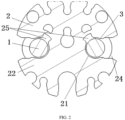
FIG. 2 illustrates a radial cross-sectional view of a self-adjusting centering terminal mounting structure according to the present disclosure. -
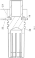
FIG. 3 illustrates an axial cross-sectional view of a self-adjusting centering terminal mounting structure according to the present disclosure. -
FIG. 4 illustrates an enlarged view of a mounting clearance inFIG. 3 . -
FIG. 5 illustrates a schematic diagram of a preset hole of a self-adjusting centering terminal mounting structure according to the present disclosure. - 1: conductive terminal; 2: terminal clamping seat; 3: mounting clearance; 4: preset hole; 12: fixed section; 14: clamping groove; 21: mounting hole; 22: mounting panel; 23: reinforcing rib; 24: passage; 25: notch; 31: radial clearance; 32: axial clearance; 141: clamping-groove bottom circumferential surface; 142: clamping-groove side surface; 213: mounting-hole top peripheral surface; 214: mounting-hole side surface.
- It should be noted that the embodiments in the present disclosure and the features in the embodiments can be combined with each other without conflict. The present disclosure will be described in detail with reference to the drawings and the embodiments.
- A self-adjusting centering terminal mounting structure, including a
conductive terminal 1 and aterminal clamping seat 2. Theconductive terminal 1 includes afixed section 12, and thefixed section 12 is externally provided with aclamping groove 14. Theterminal clamping seat 2 is internally provided with amounting hole 21. Theclamping groove 14 of theconductive terminal 1 is disposed in themounting hole 21, and amounting clearance 3 is formed between theclamping groove 14 and themounting hole 21, as illustrated inFIGS. 1 to 4 . - Since there is a
large mounting clearance 3 between theclamping groove 14 and themounting hole 21, theconductive terminal 1 can move freely in a certain range along an axial direction and a radial direction of themounting hole 21, so that each pair of terminals of the plugged structure can be plugged coaxially, which realizes automatic centering adjustment between theconductive terminals 1 of a plugged structure, thereby not only adapting to plugging and unplugging of different charging stands or charging gun heads, but also avoiding the spread of `failure infection'. - In this embodiment, the
mounting clearance 3 includes aradial clearance 31, which may be in a range of 0.3 mm to 3.7 mm, and theconductive terminal 1 is movable in its radial direction within theradial clearance 31. Themounting clearance 3 also includes anaxial clearance 32, which may be in a range of 0.4 mm to 12.3 mm, and theconductive terminal 1 is movable in its axial direction within theaxial clearance 32, as illustrated inFIG. 4 . Of course, the sizes of theradial clearance 31 and theaxial clearance 32 may also be determined as required. - The radial direction of the
conductive terminal 1 is an up-and-down direction inFIG. 4 , and the axial direction thereof is a left-and-right direction inFIG. 4 . Theclamping groove 14 of theconductive terminal 1 includes a clamping-groove bottomperipheral surface 141 and two clamping-groove side surfaces 142. Themounting hole 21 of theterminal clamping seat 2 includes a mounting-hole topperipheral surface 213 and two mounting-hole side surfaces 214. - Specifically, the
radial clearance 31 is a distance, when one side of the clamping-groove bottomperipheral surface 141 is close to one side of the mounting-hole topperipheral surface 213, between the other side of the clamping-groove bottomperipheral surface 141 and the other side of the mounting-hole topperipheral surface 213; theaxial clearance 32 is a maximum distance between one clamping-groove side surface 142 and the mounting-hole side surface 214 adjacent thereto. - The
radial clearance 31 and theaxial clearance 32 are provided to allow theconductive terminal 1 to have a space for angle adjustment and point at different angles. However, if the angle is too large, theconductive terminal 1 will touch other parts of the charging stand and cause bumping, resulting in damage to theconductive terminal 1 or other parts. - Therefore, the inventor uses different
radial clearances 31 andaxial clearances 32 to repeatedly test and observe which combinations of theradial clearance 31 and theaxial clearance 32 would cause theconductive terminal 1 to touch other components. The inventor selects tenconductive terminals 1 with the same diameter for tests, sets differentradial clearances 31 andaxial clearances 32 to match thesame mounting hole 21, observes whether theconductive terminals 1 touch other devices, and records the results. The test results are shown in Table 1. - In this embodiment, it is ideal that the
conductive terminals 1 do not touch other devices.

- As can be seen from Table 1, if the
radial clearance 31 is greater than 3.7 mm, theconductive terminal 1 will touch other components of the charging stand regardless of the axial clearance, so 3.7 mm is the maximum value of theradial clearance 31; and if theaxial clearance 32 is greater than 12.3 mm, theconductive terminal 1 will touch other components of the charging stand regardless of the radial clearance, so 12.3 mm is the maximum value of theaxial clearance 32. However, if theradial clearance 31 is less than 0.3 mm or the axial clearance is less than 0.4 mm, the centering amount of theconductive terminal 1 is too small to have practical application significance. Therefore, the inventor selects theradial clearance 31 of 0.3 mm to 3.7 mm and theaxial clearance 32 of 0.4 mm to 12.3 mm as a preferable choice. The above ranges have the following advantages: it can ensure the effectiveness of product centering, improve the service life of the terminals, and reduce the contact resistance to avoid the risks of an excessive temperature rise and a fire caused by mis-centering. Meanwhile, the inventor finds in practical works that if theradial clearance 31 or theaxial clearance 32 is too small, the mounting is difficult, and the plating layer on theconductive terminal 1 may be easily scraped off during the mounting. However, if the clearance is too large, theconductive terminal 1 will easily have more impacts with theterminal clamping seat 2, so the inventor selects theradial clearance 31 of 0.5 mm to 2 mm and theaxial clearance 32 of 1 mm to 8 mm as a more preferable choice. - Meanwhile, in order to verify the influence of different
radial clearances 31 andaxial clearances 32 on the `failure infection' of theconductive terminal 1, the inventor conducts relevant tests. The test method is to select ten groups of charging stands, set different combinations ofradial clearances 31 andaxial clearances 32 respectively, then plug the ten groups of charging stands with ten groups of brand-new mating charging gun heads respectively, and observe whether the terminals of the charging gun heads have the phenomenon of `failure infection', which is manifested as that the connection between the terminals is too tight or the plating layer on the terminal surface is scraped off. If there is a `failure infection' phenomenon, it is considered as unqualified.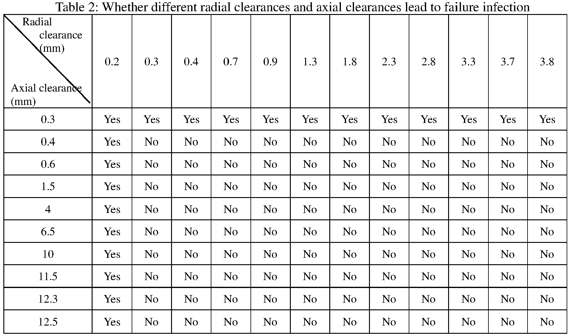
- As shown in Table 2, if the
axial clearance 32 is less than 0.4mm, the `failure infection' occurs regardless of theradial clearance 31, because the space for moving in the axial direction is too small, which is manifested as that the connection is too tight or even the plating layer on the surface of the movable test terminal is scraped off, thereby affecting the normal use. Similarly, the inventor finds that if the radial clearance is less than 0.3 mm, the `failure infection' occurs regardless of the axial clearance, because the space for moving in the radial direction is too small, which is also manifested as that the connection is too tight or even the plating layer on the surface of the movable test terminal is scraped off, thereby affecting the normal use. Therefore, in combination with Table 1, the inventor selects theradial clearance 31 of 0.3 mm to 3.7 mm and theaxial clearance 32 of 0.4 mm to 12.3 mm as a preferable choice. - Meanwhile, the inventor also tests the centering effect. The test method is to take several brand-new charging stands of the same specification, each having two mating terminals; the inventor selects the
conductive terminals 1 with different combinations of theaxial clearances 32 and theradial clearances 31 to be respectively plugged with 100 charging stands, and if the plugging is successful at one time, it is considered as qualified. The one-time plugging success rate of each combination with 100 charging stands is recorded, and the success rate reaching 95% is qualified. The results are shown in Table 3.
- As can be seen from Table 3, if the
axial clearance 32 is less than 0.4 mm, the centering success rate cannot reach the qualified level of 95% regardless of theradial clearance 31; and if theradial clearance 31 is less than 0.3 mm, the centering success rate cannot reach the qualified level of 95% regardless of theaxial clearance 32. Meanwhile, if theradial clearance 31 is greater than 3.8 mm or theaxial clearance 32 is greater than 12.3 mm, the plugging success rate is also less than 95% due to the excessive swing of theconductive terminal 1. Therefore, in combination with Table 1, the inventor selects theradial clearance 31 of 0.3 mm to 3.7 mm and theaxial clearance 32 of 0.4 mm to 12.3 mm as a preferable choice. - In this embodiment, an elastic soft rubber ring of solid or hollow structure may also be provided between the clamping
groove 14 and the mountinghole 21. The elastic soft rubber ring has a concave cross-section, and is matched and sleeved between the clampinggroove 14 of theconductive terminal 1 and the mountinghole 21 of theterminal clamping seat 2. The elastic soft rubber ring may be made of existing rubber, and can prevent theconductive terminal 1 from accidentally falling off theterminal clamping seat 2, and also play a buffering role when theconductive terminal 1 is plugged into the mountinghole 21, so as to reduce the impact of theconductive terminal 1 on theterminal clamping seat 2. - In this embodiment, the
terminal clamping seat 2 includes a mountingpanel 22 on which the mountinghole 21 is located. For example, the mountingpanel 22 may be provided with two or three mountingholes 21. Accordingly, the self-adjusting centering terminal mounting structure includes two or threeconductive terminals 1, which are plugged into the mounting holes 21 on a one-to-one basis. - In this embodiment, the
terminal clamping seat 2 further includes reinforcingribs 23, which are located around the mountinghole 21 and disposed perpendicular to the mountingpanel 22. In this embodiment, the reinforcingribs 23 are used to enhance the strength of the part of the mountingpanel 22 at the mountinghole 21. The reinforcingribs 23 are located at the back of the mountingpanel 22 and around the mountinghole 21, and have arc-shaped cross-sections. - In this embodiment, for the convenience of mounting, a
passage 24 is provided between an edge of the mountingpanel 22 and the mountinghole 21, and the clampinggroove 14 of theconductive terminal 1 can enter the mountinghole 21 via thepassage 24 that may be referred to as a first passage. A width of thepassage 24 is smaller than a diameter of the mountinghole 21. - In an exemplary embodiment, the mounting
panel 22 further includes apreset hole 4 and apassage 24 that may be referred to as a second passage. As illustrated inFIG. 5 , thepreset hole 4 is in communication with the mountinghole 21 through thepassage 24, and a diameter of thepreset hole 4 is greater than a maximum cross-sectional diameter of theconductive terminal 1. If the mountinghole 21 is not disposed at the edge of theterminal clamping seat 2, theconductive terminal 1 cannot be pushed into the mountinghole 21 from the lateral side of theterminal clamping seat 2. In this case, theconductive terminal 1 may be inserted into thepreset hole 4 from above or below theterminal clamping seat 2, and then the clampinggroove 14 may enter the mountinghole 21 through thepassage 24 to complete the mounting of theconductive terminal 1. Both or one of the first passage and the second passage may be existed provided. - In an exemplary embodiment, a ratio of a minimum width of the
passage 24 to a minimum diameter of the clamping groove 14 (i.e., a diameter of the clampinggroove 14 at the clamping-groove bottom peripheral surface 141) is 93% to 98.5%. That is, the width of thepassage 24 is smaller than the radial cross-sectional diameter of the clampinggroove 14, so that theconductive terminal 1 will not fall off the mountinghole 21 when theconductive terminal 1 is assembled with theterminal clamping seat 2. However, if thepassage 24 is too narrow, the assembly is difficult. In order to verify the influence of the ratio of the minimum width of thepassage 24 to the minimum diameter of the clampinggroove 14 on the assembly effect, the inventor conducts relevant experiments. The experiment method is to push theconductive terminal 1 to make it clamp with theterminal clamping seat 2 from thepassage 24 using a pushing force of 50 N; if theconductive terminal 1 can be pushed into theterminal clamping seat 2, it is considered as qualified, and otherwise unqualified; theterminal clamping seat 2 after plugging is subjected to a shaking experiment with a frequency of 8 Hz, which is similar to the driving environment, for a duration of 2 minutes, and if theconductive terminal 1 falls off the mountinghole 21, it is considered as unqualified, and otherwise qualified. The experiment results are shown in Table 4.Table 4: Influence of a ratio of the minimum width of the passage to the minimum diameter of the clamping groove on the assembly Ratio (%) 91% 92% 93% 94% 95% 96% 97% 98% 98.5% 99% Whether pushed into No No Yes Yes Yes Yes Yes Yes Yes Yes Whether fall off No No No No No No No No No Yes - As can be seen from Table 4, if the ratio of the minimum width of the
passage 24 to the radial cross-sectional diameter of the clampinggroove 14 is less than 93%, the assembly cannot be done under the pushing force of 50 N, because the minimum width of thepassage 24 is much smaller than the radial cross-sectional diameter of the clamping groove. Therefore, the inventor selects the ratio of the minimum width of thepassage 24 to the diameter of the clampinggroove 14 being at least 93%. As also can be seen from Table 2, if the ratio of the minimum width of thepassage 24 to the radial cross-sectional diameter of the clampinggroove 14 is greater than 98.5%, theconductive terminal 1 will fall off the mountinghole 21 in the vibration experiment, which cannot meet the actual working requirement, so the inventor selects the ratio of the minimum width of thepassage 24 to the radial cross-sectional diameter of the clampinggroove 14 being 93% to 98.5%. Specifically, the ratio may be 98%, 97.5%, 97%, 96%, 95% or the like. In a specific embodiment, the radial cross-sectional diameter of the clampinggroove 14 is 8 mm, and the minimum width of thepassage 24 is 7.8 mm. - In this embodiment, the mounting
panel 22 is provided with anotch 25, which is in communication with the mountinghole 21, and thenotch 25 and thepassage 24 are located on two sides of the mountinghole 21 respectively. The notch enables thepassage 24 to maintain a resilience. When theconductive terminal 1 passes through thepassage 24, both sides of thepassage 24 are squeezed and more likely to be deformed due to thenotch 25, thereby ensuring that theconductive terminal 1 can more easily enter the mountinghole 21. - In this embodiment, an assembly force between the clamping
groove 14 and thepassage 24 is 6 N to 55 N. In order to plug theconductive terminal 1 into the mountinghole 21 of theterminal clamping seat 2, a certain assembly force is required. If the assembly force is too small, theconductive terminal 1 cannot be plugged, and if the assembly force is too large, theconductive terminal 1 or theterminal clamping seat 2 will be easily damaged. In order to verify the influence of the assembly force between the clampinggroove 14 and thepassage 24 on the plugging effect, the inventor conducts relevant experiments. The experiment method is to select the sameconductive terminals 1 and the sameterminal clamping seats 2, and plugs theconductive terminal 1 into theterminal clamping seat 2 with different forces. It is considered as qualified if the plugging is smooth without damaging theconductive terminal 1 or theterminal clamping seat 2, and otherwise unqualified. The experimental results are shown in Table 5.Table 5: Influence of different assembly forces between the clamping groove and the passage on the plugging effect Plugging force (N) 5 6 7 8 10 20 30 40 48 52 55 60 Whether plugged into No Yes Yes Yes Yes Yes Yes Yes Yes Yes Yes Yes Whether damaged No No No No No No No No No No No Yes - As can be seen from Table 5, if the assembly force is less than 6 N, the
conductive terminal 1 cannot be plugged into theterminal clamping seat 2. Therefore, the inventor selects the minimum assembly force to be 6 N. If the assembly force is greater than 55 N, theconductive terminal 1 is damaged, which is manifested in scratches in the clampinggroove 14. Therefore, the inventor selects the assembly force between the clampinggroove 14 and thepassage 24 to be 6 N to 55 N. The specific plugging force may be 8 N, 10 N, 15 N, 25 N, etc. - In this embodiment, the material of the mounting
panel 22 has an impact strength of 115 MPa to 1300 MPa. The impact strength is used to evaluate the impact resistance of a material or to judge the brittleness and toughness of the material, so the impact strength is also called impact toughness. The impact strength can directly reflect the impact resistance of the material. In this embodiment, if the impact strength of the mountingpanel 22 is too small, theconductive terminal 1 will damage theterminal clamping seat 2 when being plugged into theterminal clamping seat 2, and if the impact strength of the mountingpanel 22 is too large, theterminal clamping seat 2 cannot be deformed and then cannot be plugged. In order to select a suitable material to make the mountingpanel 22, the inventor conducts experiments. The experiment method is to select the same impact test environment and the mountingpanels 22 of the same specification but different impact strengths, and use an external force of 55 N to carry out impact tests on the mounting panels. It is considered as qualified if the mounting panel is not deformed after the impact, and otherwise unqualified. The results are shown in Table 6.Table 6: Influence of mounting panels made of materials with different impact strengths on the plugging effect Impact strength (MPa) 110 115 130 150 200 400 650 800 100 1200 1300 1350 Whether deformed Yes No No No No No No No No No No No - As can be seen from Table 6, if the impact strength of the material of the mounting
panel 22 is less than 115 MPa, the mountingpanel 22 is deformed in the impact experiments, and a long-term use of the mounting panel made of the material with such impact strength will inevitably lead to the damage of the mountingpanel 22 and further lead to the failure of the charging device. Thus, the inventor selects the minimum impact strength of the material of the mountingpanel 22 to be 115 MPa. If the impact strength of the material is greater than 1300 MPa, material selection and processing of the mountingpanel 22 are very difficult, and it is not easy to plug theconductive terminal 1 into the mountingpanel 22. Therefore, the inventor prefers that the impact strength of the material of the mountingpanel 22 is 115 MPa to 1300 MPa, and specifically, 120 MPa, 130 MPa, 140 MPa, 150 MPa, 300 MPa, 450 MPa, etc. - The mounting and working processes of the self-adjusting centering terminal mounting structure are introduced below.
- The clamping
groove 14 of theconductive terminal 1 is disposed in the mountinghole 21, with apreset mounting clearance 3 formed therebetween, and the self-adjusting centering terminal mounting structure is mounted in the charging stand. The terminal in the charging gun head is correspondingly plugged with theconductive terminal 1 that is freely movable in a certain range along the axial direction and radial direction of the mountinghole 21 to adjust the position, so that the axes of each pair of corresponding terminal andconductive terminal 1 are coincident. - The clamping
groove 14 of theconductive terminal 1 is disposed in the mountinghole 21, with apreset mounting clearance 3 formed therebetween, and the self-adjusting centering terminal mounting structure is mounted in the charging gun head. The terminal in the charging stand is correspondingly plugged with theconductive terminal 1 that is freely movable in a certain range along the axial direction and radial direction of the mountinghole 21 to adjust the position, so that the axes of each pair of corresponding terminal andconductive terminal 1 are coincident. - Those described above are only specific embodiments of the present disclosure, rather than limitations to the scope thereof, so the replacement of the equivalent components or the equivalent variations and modifications made according to the patent protection scope of the present disclosure should fall within to the scope of the patent. In addition, free combinations can be made between the technical features, between the technical features and the technical solutions, and between the technical solutions in the present disclosure.
Claims (11)
- A self-adjusting centering terminal mounting structure, comprising a conductive terminal (1) and a terminal clamping seat (2), wherein the conductive terminal (1) comprises a fixed section (12), the fixed section (12) is externally provided with a clamping groove (14), the terminal clamping seat (2) is internally provided with a mounting hole (21), the clamping groove (14) of the conductive terminal (1) is disposed in the mounting hole (21), and a mounting clearance (3) is formed between the clamping groove (14) and the mounting hole (21).
- The self-adjusting centering terminal mounting structure according to claim 1, wherein the mounting clearance (3) comprises a radial clearance (31) which is in a range of 0.3 mm to 3.7 mm, and the conductive terminal (1) is movable in its radial direction within the range of the radial clearance (31).
- The self-adjusting centering terminal mounting structure according to claim 1, wherein the mounting clearance (3) comprises an axial clearance (32) which is in a range of 0.4 mm to 12.3 mm, and the conductive terminal (1) is movable in its axial direction within the range of the axial clearance (32).
- The self-aligning terminal mounting structure according to claim 1, wherein the terminal clamping seat (2) comprises a mounting panel (22), on which the mounting hole (21) is located.
- The self-adjusting and centering terminal mounting structure according to claim 4, wherein the terminal clamping seat (2) further comprises reinforcing ribs (23), which are located around the mounting hole (21) and disposed perpendicular to the mounting panel (22).
- The terminal mounting structure with self-adjustment and centering according to claim 4, wherein a passage (24) is disposed between an edge of the mounting panel (22) and the mounting hole (21), and the clamping groove (14) of the conductive terminal (1) is capable of entering the mounting hole (21) via the passage (24).
- The self-aligning terminal mounting structure according to claim 4, wherein the mounting panel (22) is provided with a preset hole (4) and a passage (24), the preset hole (4) is in communication with the mounting hole (21) through the passage (24), a diameter of the preset hole (4) is greater than a maximum diameter of the conductive terminal (1), and the clamping groove (14) of the conductive terminal (1) is capable of firstly entering the preset hole (4) and then entering the mounting hole (21) through the passage (24).
- The self-adjusting centering terminal mounting structure according to claim 6 or 7, wherein a ratio of a minimum width of the passage (24) to a minimum diameter of the clamping groove (14) is 93% to 98.5%.
- The self-adjusting and centering terminal mounting structure according to claim 6 or 7, wherein the mounting panel (22) is provided with a notch (25) which is in communication with the mounting hole (21), and the notch (25) and the passage (24) are located on two sides of the mounting hole (21) respectively.
- The terminal mounting structure of self-adjusting centering according to claim 6 or 7, wherein an assembly force between the clamping groove (14) and the passage (24) is 6 N to 55 N.
- The self-aligning terminal mounting structure according to claim 4, wherein an impact strength of a material of the mounting panel (22) is 115 MPa to 1300 MPa.
Applications Claiming Priority (2)
| Application Number | Priority Date | Filing Date | Title |
|---|---|---|---|
| CN202122029997.1U CN215816490U (en) | 2021-08-26 | 2021-08-26 | Self-adjusting centering terminal mounting structure |
| PCT/CN2022/114697 WO2023025227A1 (en) | 2021-08-26 | 2022-08-25 | Self-adjusting centering terminal mounting structure |
Publications (3)
| Publication Number | Publication Date |
|---|---|
| EP4395082A1 true EP4395082A1 (en) | 2024-07-03 |
| EP4395082A4 EP4395082A4 (en) | 2025-04-02 |
| EP4395082B1 EP4395082B1 (en) | 2026-04-15 |
Family
ID=80151892
Family Applications (1)
| Application Number | Title | Priority Date | Filing Date |
|---|---|---|---|
| EP22860573.9A Active EP4395082B1 (en) | 2021-08-26 | 2022-08-25 | Self-adjusting centering terminal mounting structure |
Country Status (4)
| Country | Link |
|---|---|
| US (1) | US20240343139A1 (en) |
| EP (1) | EP4395082B1 (en) |
| CN (1) | CN215816490U (en) |
| WO (1) | WO2023025227A1 (en) |
Families Citing this family (2)
| Publication number | Priority date | Publication date | Assignee | Title |
|---|---|---|---|---|
| CN215816490U (en) * | 2021-08-26 | 2022-02-11 | 长春捷翼汽车零部件有限公司 | Self-adjusting centering terminal mounting structure |
| TWI903848B (en) * | 2024-11-05 | 2025-11-01 | 財團法人金屬工業研究發展中心 | Terminal set for charging and terminal block |
Family Cites Families (6)
| Publication number | Priority date | Publication date | Assignee | Title |
|---|---|---|---|---|
| US4968263A (en) * | 1990-03-28 | 1990-11-06 | Molex Incorporated | Multi-pin electrical connector with floating terminal pins |
| US6699054B1 (en) * | 2003-01-15 | 2004-03-02 | Applied Engineering Products, Inc. | Float mount coaxial connector |
| CA2453637C (en) * | 2003-12-18 | 2009-04-07 | Weco Electrical Connectors Inc. | Self-locking terminal pin |
| CN102769223A (en) * | 2011-05-04 | 2012-11-07 | 富士康(昆山)电脑接插件有限公司 | socket connector |
| CN208444990U (en) * | 2018-07-16 | 2019-01-29 | 广东林一新能源科技有限公司 | Automobile cradle and automobile |
| CN215816490U (en) * | 2021-08-26 | 2022-02-11 | 长春捷翼汽车零部件有限公司 | Self-adjusting centering terminal mounting structure |
-
2021
- 2021-08-26 CN CN202122029997.1U patent/CN215816490U/en active Active
-
2022
- 2022-08-25 US US18/685,441 patent/US20240343139A1/en active Pending
- 2022-08-25 EP EP22860573.9A patent/EP4395082B1/en active Active
- 2022-08-25 WO PCT/CN2022/114697 patent/WO2023025227A1/en not_active Ceased
Also Published As
| Publication number | Publication date |
|---|---|
| CN215816490U (en) | 2022-02-11 |
| EP4395082A4 (en) | 2025-04-02 |
| US20240343139A1 (en) | 2024-10-17 |
| EP4395082B1 (en) | 2026-04-15 |
| WO2023025227A1 (en) | 2023-03-02 |
Similar Documents
| Publication | Publication Date | Title |
|---|---|---|
| EP4395082B1 (en) | Self-adjusting centering terminal mounting structure | |
| EP2485335B1 (en) | Contactor and electrical connection device | |
| EP4442545A1 (en) | Dustproof device having self-locking and rebounding functions, and charging device | |
| WO2018133871A1 (en) | Elastic pole, combined member, high-voltage assembly, electrical connector, and battery charging board | |
| CN106680540B (en) | Coaxial connector for probing | |
| US20120071040A1 (en) | Terminal contacting part included in a jig for charging and discharging a secondary battery and the jig including the same | |
| WO2001037381A1 (en) | Ic socket and ic tester | |
| KR101813006B1 (en) | Contactor for semiconductor test | |
| US8111073B2 (en) | Testing device | |
| CN113391242B (en) | A connector terminal assembly positioning rapid detection fixture | |
| CN205333754U (en) | Connecting terminal's testing arrangement | |
| CN220961823U (en) | Test fixture for current sensor | |
| CN219936038U (en) | Three-temperature test fixture for BGA radio frequency assembly | |
| CN208461177U (en) | A kind of assemble mechanism based on electric connector | |
| KR20040073353A (en) | Active part for a surge arrester | |
| EP3696555B1 (en) | Probe device of floating structure | |
| CN112701516B (en) | Adopt nickel plating gilt structure to have CY43 electric connector of jack | |
| CN217425876U (en) | Test probe and test device | |
| CN221446173U (en) | Clamp for testing and testing equipment | |
| CN113125936A (en) | Aging test device | |
| CN207233966U (en) | One kind experiment wire terminal and wire connecting fabric | |
| CN217954676U (en) | Charge and discharge test fixture and energy storage equipment test tooling | |
| CN222422447U (en) | An electrical connector | |
| CN220272797U (en) | High-current multi-pin charging connector | |
| CN213878535U (en) | Industrial flip socket |
Legal Events
| Date | Code | Title | Description |
|---|---|---|---|
| STAA | Information on the status of an ep patent application or granted ep patent |
Free format text: STATUS: THE INTERNATIONAL PUBLICATION HAS BEEN MADE |
|
| PUAI | Public reference made under article 153(3) epc to a published international application that has entered the european phase |
Free format text: ORIGINAL CODE: 0009012 |
|
| STAA | Information on the status of an ep patent application or granted ep patent |
Free format text: STATUS: REQUEST FOR EXAMINATION WAS MADE |
|
| 17P | Request for examination filed |
Effective date: 20240318 |
|
| AK | Designated contracting states |
Kind code of ref document: A1 Designated state(s): AL AT BE BG CH CY CZ DE DK EE ES FI FR GB GR HR HU IE IS IT LI LT LU LV MC MK MT NL NO PL PT RO RS SE SI SK SM TR |
|
| P01 | Opt-out of the competence of the unified patent court (upc) registered |
Free format text: CASE NUMBER: APP_43258/2024 Effective date: 20240724 |
|
| DAV | Request for validation of the european patent (deleted) | ||
| DAX | Request for extension of the european patent (deleted) | ||
| A4 | Supplementary search report drawn up and despatched |
Effective date: 20250304 |
|
| RIC1 | Information provided on ipc code assigned before grant |
Ipc: B60L 53/16 20190101ALN20250226BHEP Ipc: H01R 13/40 20060101ALI20250226BHEP Ipc: H01R 13/631 20060101AFI20250226BHEP |
|
| GRAP | Despatch of communication of intention to grant a patent |
Free format text: ORIGINAL CODE: EPIDOSNIGR1 |
|
| STAA | Information on the status of an ep patent application or granted ep patent |
Free format text: STATUS: GRANT OF PATENT IS INTENDED |
|
| RIC1 | Information provided on ipc code assigned before grant |
Ipc: H01R 13/631 20060101AFI20251030BHEP Ipc: H01R 13/40 20060101ALI20251030BHEP Ipc: B60L 53/16 20190101ALN20251030BHEP |
|
| INTG | Intention to grant announced |
Effective date: 20251118 |
|
| GRAS | Grant fee paid |
Free format text: ORIGINAL CODE: EPIDOSNIGR3 |
|
| GRAA | (expected) grant |
Free format text: ORIGINAL CODE: 0009210 |
|
| STAA | Information on the status of an ep patent application or granted ep patent |
Free format text: STATUS: THE PATENT HAS BEEN GRANTED |
|
| AK | Designated contracting states |
Kind code of ref document: B1 Designated state(s): AL AT BE BG CH CY CZ DE DK EE ES FI FR GB GR HR HU IE IS IT LI LT LU LV MC MK MT NL NO PL PT RO RS SE SI SK SM TR |
|
| REG | Reference to a national code |
Ref country code: CH Ref legal event code: F10 Free format text: ST27 STATUS EVENT CODE: U-0-0-F10-F00 (AS PROVIDED BY THE NATIONAL OFFICE) Effective date: 20260415 |
|
| REG | Reference to a national code |
Ref country code: DE Ref legal event code: R096 Ref document number: 602022034768 Country of ref document: DE |