EP4395060A1 - Battery cell, battery, and electric device - Google Patents
Battery cell, battery, and electric device Download PDFInfo
- Publication number
- EP4395060A1 EP4395060A1 EP22948875.4A EP22948875A EP4395060A1 EP 4395060 A1 EP4395060 A1 EP 4395060A1 EP 22948875 A EP22948875 A EP 22948875A EP 4395060 A1 EP4395060 A1 EP 4395060A1
- Authority
- EP
- European Patent Office
- Prior art keywords
- isolation member
- battery cell
- protrusion
- battery
- clearance groove
- Prior art date
- Legal status (The legal status is an assumption and is not a legal conclusion. Google has not performed a legal analysis and makes no representation as to the accuracy of the status listed.)
- Pending
Links
Images


Classifications
-
- H—ELECTRICITY
- H01—ELECTRIC ELEMENTS
- H01M—PROCESSES OR MEANS, e.g. BATTERIES, FOR THE DIRECT CONVERSION OF CHEMICAL ENERGY INTO ELECTRICAL ENERGY
- H01M50/00—Constructional details or processes of manufacture of the non-active parts of electrochemical cells other than fuel cells, e.g. hybrid cells
- H01M50/10—Primary casings; Jackets or wrappings
- H01M50/147—Lids or covers
- H01M50/148—Lids or covers characterised by their shape
- H01M50/15—Lids or covers characterised by their shape for prismatic or rectangular cells
-
- H—ELECTRICITY
- H01—ELECTRIC ELEMENTS
- H01M—PROCESSES OR MEANS, e.g. BATTERIES, FOR THE DIRECT CONVERSION OF CHEMICAL ENERGY INTO ELECTRICAL ENERGY
- H01M50/00—Constructional details or processes of manufacture of the non-active parts of electrochemical cells other than fuel cells, e.g. hybrid cells
- H01M50/50—Current conducting connections for cells or batteries
- H01M50/528—Fixed electrical connections, i.e. not intended for disconnection
-
- H—ELECTRICITY
- H01—ELECTRIC ELEMENTS
- H01M—PROCESSES OR MEANS, e.g. BATTERIES, FOR THE DIRECT CONVERSION OF CHEMICAL ENERGY INTO ELECTRICAL ENERGY
- H01M50/00—Constructional details or processes of manufacture of the non-active parts of electrochemical cells other than fuel cells, e.g. hybrid cells
- H01M50/50—Current conducting connections for cells or batteries
- H01M50/531—Electrode connections inside a battery casing
- H01M50/533—Electrode connections inside a battery casing characterised by the shape of the leads or tabs
-
- H—ELECTRICITY
- H01—ELECTRIC ELEMENTS
- H01M—PROCESSES OR MEANS, e.g. BATTERIES, FOR THE DIRECT CONVERSION OF CHEMICAL ENERGY INTO ELECTRICAL ENERGY
- H01M50/00—Constructional details or processes of manufacture of the non-active parts of electrochemical cells other than fuel cells, e.g. hybrid cells
- H01M50/50—Current conducting connections for cells or batteries
- H01M50/572—Means for preventing undesired use or discharge
- H01M50/584—Means for preventing undesired use or discharge for preventing incorrect connections inside or outside the batteries
- H01M50/586—Means for preventing undesired use or discharge for preventing incorrect connections inside or outside the batteries inside the batteries, e.g. incorrect connections of electrodes
-
- H—ELECTRICITY
- H01—ELECTRIC ELEMENTS
- H01M—PROCESSES OR MEANS, e.g. BATTERIES, FOR THE DIRECT CONVERSION OF CHEMICAL ENERGY INTO ELECTRICAL ENERGY
- H01M50/00—Constructional details or processes of manufacture of the non-active parts of electrochemical cells other than fuel cells, e.g. hybrid cells
- H01M50/50—Current conducting connections for cells or batteries
- H01M50/572—Means for preventing undesired use or discharge
- H01M50/584—Means for preventing undesired use or discharge for preventing incorrect connections inside or outside the batteries
- H01M50/59—Means for preventing undesired use or discharge for preventing incorrect connections inside or outside the batteries characterised by the protection means
- H01M50/593—Spacers; Insulating plates
-
- H—ELECTRICITY
- H01—ELECTRIC ELEMENTS
- H01M—PROCESSES OR MEANS, e.g. BATTERIES, FOR THE DIRECT CONVERSION OF CHEMICAL ENERGY INTO ELECTRICAL ENERGY
- H01M50/00—Constructional details or processes of manufacture of the non-active parts of electrochemical cells other than fuel cells, e.g. hybrid cells
- H01M50/60—Arrangements or processes for filling or topping-up with liquids; Arrangements or processes for draining liquids from casings
- H01M50/609—Arrangements or processes for filling with liquid, e.g. electrolytes
- H01M50/627—Filling ports
-
- Y—GENERAL TAGGING OF NEW TECHNOLOGICAL DEVELOPMENTS; GENERAL TAGGING OF CROSS-SECTIONAL TECHNOLOGIES SPANNING OVER SEVERAL SECTIONS OF THE IPC; TECHNICAL SUBJECTS COVERED BY FORMER USPC CROSS-REFERENCE ART COLLECTIONS [XRACs] AND DIGESTS
- Y02—TECHNOLOGIES OR APPLICATIONS FOR MITIGATION OR ADAPTATION AGAINST CLIMATE CHANGE
- Y02E—REDUCTION OF GREENHOUSE GAS [GHG] EMISSIONS, RELATED TO ENERGY GENERATION, TRANSMISSION OR DISTRIBUTION
- Y02E60/00—Enabling technologies; Technologies with a potential or indirect contribution to GHG emissions mitigation
- Y02E60/10—Energy storage using batteries
Definitions
- the present application relates to the technical field of battery, and in particular to a battery cell, a battery and an electricity consuming apparatus.
- the present application provides a battery cell, a battery and an electricity consuming apparatus that can improve battery performance.
- At least a portion of an inner wall surface of the clearance groove abuts against an outer surface of the protrusion.
- a depth L1 of the clearance groove accounts for 20% - 80% of a thickness L of the isolation member.
- the depth L1 of the clearance groove accounts for 20% - 80% of the thickness L of the isolation member, preventing the clearance groove from interfering with the protrusion due to the depth L 1 of the clearance groove being too small, and also improving the insufficient limiting effect of the clearance groove on the position of the protrusion due to the depth of the clearance groove being too excessive.
- an orthographic projection of the clearance groove coincides with an orthographic projection of the protrusion.
- the orthographic projection of the clearance groove coincides with the orthographic projection of the protrusion, and the outer surface of the protrusion abuts fully against the clearance groove, so the clearance groove has a greater limiting effect on the position of the protrusion.
- two or more clearance grooves spaced apart in a first direction are provided on the side of the isolation member facing away from the cap plate; and the electrode assembly is provided with two or more protrusions spaced apart in the first direction, each of the protrusions is located correspondingly in each of the clearance grooves; or the electrode assembly is provided with one protrusion, and the one protrusion is located in one of the clearance grooves.
- two or more clearance grooves spaced apart along the first direction are provided on the side of the isolation member facing away from the cap plate; the electrode assembly is provided with two or more protrusions spaced apart along the first direction, and each of the protrusions is correspondingly located in each of the clearance grooves; alternatively, the electrode body is provided with one protrusion, and the one protrusion is located in one of the clearance grooves.
- the clearance groove disposed may be compatible with various protrusions, improving the compatibility of the isolation member.
- a distance between the two clearance grooves in the first direction is at least 20% of a length of the cap assembly.
- the distance between the two clearance grooves is at least 20% of the length of the cap assembly, preventing a short-circuit connection in the battery due to the electrode body being misaligned, which is caused by the distance between the two clearance grooves being too small and the fixing capacity of the isolation member on the electrode body being insufficient.
- the two clearance grooves are symmetrically disposed relative to an axis extending in a second direction, and the first direction intersects with the second direction.
- the symmetrically disposed clearance groove has low machining difficulty and is convenient for manufacturing.
- the isolation member is provided with an abutment portion protruding toward the electrode assembly, the abutment portion is configured to abut against the electrode body, and the clearance groove is disposed at the abutment portion.
- the isolation member includes the abutment portion protruding toward the electrode assembly, and the abutment portion abuts against the electrode body, improving the problem of short circuit in the battery caused by misalignment of the electrode body under the action of external force.
- the isolation member further includes a liquid injection hole disposed to be penetrated, and the liquid injection hole is staggered with the clearance groove.
- the liquid injection hole is configured to fill the electrolyte into the electrode assembly, and the liquid injection hole is staggered with the clearance groove, preventing the protrusion from blocking the liquid injection hole.
- the battery cell further includes a connector, which is connected to the tab and is staggered with the clearance groove.
- the connector is connected to the tab, and the connector is staggered with the clearance groove, preventing the possibility of the clearance groove not being able to abut against the protrusion due to a portion of the connector entering the clearance groove.
- the battery cell further includes a connector, which is connected to the protrusion, and at least a portion of the connector is located in the clearance groove.
- the clearance groove is disposed between two tabs adjacent in the first direction.
- the battery cell further includes an explosion proof valve hole penetrating through the cap plate, the isolation member is provided with a vent hole in communication with the explosion proof valve hole, and the vent hole is staggered with the clearance groove.
- the isolation member is provided with the vent hole in communication with the explosion proof valve hole, and the explosion proof valve will not affect the breathability of the vent hole; the vent hole is staggered with the clearance groove, preventing the protrusion from affecting the gas exhaust of electrode assembly through the vent hole.
- the present application also provides a battery, including the battery cell in any of the embodiments mentioned above in the first aspect.
- plural means two or more; the terms “upper”, “lower”, “left”, “right”, “inner”, “outer”, etc. indicate the orientation or positional relationship, only for convenience of describing the present application and simplifying the description, rather than indicating or implying that the involved device or assembly must have a specific orientation, be configured and operated in a specific orientation, and therefore cannot be understood as a limitation of the present application.
- first, “second” and the like are only used for descriptive purposes, and cannot be understood as indicating or implying relative importance.
- perpendicular need not to be strictly perpendicular, but allows an error within an allowable range.
- parallel need not to be strictly parallel, but allows an error within an allowable range.
- the electricity consuming apparatus may be a vehicle, a mobile phone, a portable device, a notebook computer, a ship, a spacecraft, an electric toy, an electric tool or the like.
- the vehicle may be a fuel car, a gas car or a new energy car, and the new energy car may be a pure electric car, a hybrid car, a range-extended car or the like;
- the spacecraft may include an airplane, a rocket, a space shuttle, a space ship or the like;
- the electric toy may include a fixed-type or mobile-type electric toy, such as a game player, an electric car toy, an electric ship toy, an electric airplane toy or the like;
- the power tool may include a metal cutting power tool, a grinding power tool, an assembly power tool and a railway power tools, such as an electric drill, an electric grinder, an electric wrench, an electric screwdriver, an electric hammer, an impact drill, a concrete vibrator, an electric planers or the like.
- the casing 4 is an assembly configured to cooperate with the cap assembly 6 to form an internal environment of the battery cell 3, wherein the formed internal environment may be configured to accommodate the electrode assembly 5, the electrolyte (not shown in the figure), and other components.
- the casing 4 and the cap assembly 6 may be independent components, an opening may be provided on the casing 4, and the internal environment of the battery cell 3 may be formed by closing the opening at the cap assembly 6,.
- the cap assembly 6 and the casing 4 may also be integral.
- the cap assembly 6 and the casing 4 may firstly form a common connection face before other components enter the casing, and when the interior of the casing 4 is required to be encapsulated, the cap assembly 6 may be then covered onto the casing 4.
- the battery cell 3 includes a cap assembly 6 and an electrode assembly 5
- the cap assembly 6 includes a cap plate 62 and an isolation member 63
- the isolation member 63 is disposed on one side of the cap plate 62
- the electrode assembly 5 is disposed on a side of the isolation member 63 facing away from the cap plate 62
- the electrode assembly 5 includes an electrode body 51 and tabs 52 protruding from the electrode body 51
- a protrusion 521 connected with the electrode body 51 is provided on a peripheral side of at least one of the tabs 52
- a clearance groove 631 is provided on a surface of the isolation member 63 facing away from the cap plate 62 and is configured to accommodate at least a portion of the protrusion 521.
- Fig. 7 shows a structural schematic diagram of another battery cell 3 provided in an embodiment of the present application.
- the clearance groove 631 is provided on a surface of the isolation member 63 facing away from the cap plate 62 and accommodates at least a portion of the protrusion 521, improving the problem of insertion of the tab 52 caused by the interference of the isolation member 63 with the protrusion 521, improving the cooperation relationship between the isolation member 63 and the tab 52, and improving the battery performance.
- a depth L1 of the clearance groove 631 accounts for 20% - 80% of a thickness L of the isolation member 63.
- Fig. 9 shows a structural schematic diagram of another battery cell provided in an embodiment of the present application
- Fig. 10 shows a structural schematic diagram of an isolation member of another battery cell provided in an embodiment of the present application.
- two or more clearance grooves 631 spaced apart along the first direction X are provided on the side of the isolation member 63 facing away from the cap plate 62; the electrode assembly 5 is provided with two or more protrusions 521 spaced apart along the first direction X, and each of the protrusions 521 is correspondingly located in each of the clearance grooves 631.
- the electrode body 51 is provided with one protrusion 521, and the one protrusion 521 is located in one of the clearance grooves 631. With such an arrangement, the clearance groove 631 disposed in this way may be compatible with various protrusions 521, improving the compatibility of the isolation member 63.
- Fig. 11 shows a structural schematic diagram of another battery cell 3 provided in an embodiment of the present application.
- the connector 64 is connected to the tab 52, and the connector 64 is staggered with the clearance groove 631, preventing the possibility of the clearance groove 631 not being able to abut against the protrusion 521 due to a portion of the connector 64 entering the clearance groove 631, and reducing the limiting effect of the isolation member 63 on the position of the tab 521.
- Fig. 12 shows a structural schematic diagram of another battery cell 3 provided in an embodiment of the present application.
- the battery cell further includes a connector 64, which is connected to the protrusion 521, and at least a portion of the connector 64 is located in the clearance groove 631.
- the depth of the clearance groove 631 may not be less than a sum of the thickness of the connector 64 and the thickness of the protrusion 521.
- the connector 64 is connected to the protrusion 521, and at least a portion of the connector 64 is located in the clearance groove 631, ensuring that the isolation member 63 does not interfere with the protrusion 521 via the connector 64.
- the clearance groove 631 is disposed between two adjacent tabs 52 in the first direction X.
- the protrusions 521 are disposed between two tabs 52 adjacent in the first direction X, and only a small portion of the protrusion 521 is disposed at a portion outside the two tabs 52 adjacent in the first direction X. Due to the extremely small extending distance of the portion of protrusion 521 located outside the two tabs 52 in the first direction X, this portion of the protrusion 521 is subjected to less pressure from the isolation member 63, and meantime, due to the short torque, this portion of the protrusion 521 has a relatively high ability to resist deformation. Moreover, the difficulty in manufacturing the clearance groove 631 that corresponds to this portion of the protrusion 521 is relatively high, resulting in half the effort, and thus, the clearance groove 631 is disposed between two tabs 52 adjacent in the first direction.
- the clearance groove 631 is disposed between two tabs 52 adjacent in the first direction X, reducing process difficulty and saving the cost.
- Fig. 13 shows a structural schematic diagram of the cap plate 62 of the battery cell 3 provided in an embodiment of the present application
- Fig. 14 shows a structural schematic diagram of the isolation member 63 of the battery cell 3 provided in an embodiment of the present application.
- the battery cell further includes an explosion proof valve hole 65 that penetrates through the cap plate 62; the isolation member 63 is provided with a vent hole 634 in communication with the explosion proof valve hole 65, and the vent hole 634 is staggered with the clearance groove 631.
- the explosion proof valve is configured to release the pressure inside battery cell 3 when the internal pressure or temperature of battery cell 3 reaches a threshold.
- the explosion proof valve is disposed in the middle of the cap plate 62.
- the isolation member 63 is provided with a vent hole 634, which is configured to discharge gas from the battery cell 3.
- the orthogonal projection of at least a portion of the vent hole 634 coincide with the orthogonal projection of the explosion proof valve hole 651.
- vent hole 634 is disposed in the middle of the isolation member 63.
- a plurality of the vent holes 634 are distributed on the isolation member 63 in rows and columns along the first direction X and the second direction Y
- the isolation member 63 is provided with the vent hole 634 in communication with the explosion proof valve hole 65, and the explosion proof valve will not affect the breathability of the vent hole 634; the vent hole 634 is staggered with the clearance groove 631, preventing the protrusion from affecting the gas exhaust of electrode assembly 5 through the vent hole 634.
- the battery provided in the embodiment of the present application has the same technical effect due to the use of the battery cell provided in the above embodiments, and will not be further described here.
- An embodiment of the present application also provides an electricity consuming apparatus, including the battery provided in the above embodiment, and the battery is configured to provide electrical energy.
- the electricity consuming apparatus provided in the embodiment of the present application has the same technical effect due to the use of the battery provided in the embodiment of the present application, and will not be further described here.
- the present application provides the battery cell 3 including the cap assembly 6 and the electrode assembly 5, the cap assembly 6 includes the cap plate 62 and the isolation member 63, and the isolation member 63 is disposed on one side of the cap plate 62.
- the electrode assembly 5 is disposed on the side of the isolation member 63 facing away from the cap plate 62, the electrode assembly 5 includes the electrode body 51 and tabs 52 protruding from the electrode body 51, and the protrusion 521 connected with the electrode body 51 is disposed on the peripheral side of at least one of the tabs 52.
- the clearance groove 631 is provided on the surface of the isolation member 63 facing away from the cap plate 62, the clearance groove 631 is disposed between two tabs 52 adjacent in the first direction, and the clearance groove 631 is configured to accommodate the protrusion 521; the inner wall surface of the clearance groove 631 abuts against the outer surface of the protrusion 521, and in the direction from the cap plate 62 to the isolation member 63, the orthographic projection of the clearance groove 631 coincides with the orthographic projection of the protrusion 521.
- the isolation member 63 further includes the liquid injection hole 633 disposed to be penetrated, and the liquid injection hole 633 is staggered with the clearance groove 631; the connector 64 is connected to the tab 52, and the connector 64 is staggered with the clearance groove 631; the isolation member 63 is provided with a vent hole 634 in communication with the explosion proof valve hole 65, and the vent hole 634 is staggered with the clearance groove 631.
- the cap assembly 6 includes the cap plate 62 and the isolation member 63, and the isolation member 63 is disposed on one side of the cap plate 62; the electrode terminal 61is disposed on the side of the isolation member 63 facing away from the cap plate 62, and the electrode terminal 61includes the electrode body 51 and tabs 52 protruding from the electrode body 51, the protrusion 521 connected with the electrode body 51 is disposed on the peripheral side of at least one of the tabs 52, increasing the current-flowing area between the tab 52 and the electrode body 51; the clearance groove 631 is provided on the surface of the isolation member 63 facing away from the cap plate 62, and the clearance groove 631 accommodates at least a portion of the protrusion 521, improving the problem of insertion of the tab 52 caused by the interference of the isolation member 63 with the protrusion 521, improving the cooperation relationship between the isolation member 63 and the tab 52, and improving battery performance.
Landscapes
- Chemical & Material Sciences (AREA)
- Chemical Kinetics & Catalysis (AREA)
- Electrochemistry (AREA)
- General Chemical & Material Sciences (AREA)
- Connection Of Batteries Or Terminals (AREA)
Abstract
Description
- This application claims priority to
Chinese Patent Application No. 202221624387.4, titled "BATTERY CELL, BATTERY AND ELECTRICITY CONSUMING APPARATUS" and filed on June 28, 2022 - The present application relates to the technical field of battery, and in particular to a battery cell, a battery and an electricity consuming apparatus.
- Energy conservation and emission reduction are key to the sustainable development of the automotive industry, and the electric vehicle has become an important component of the sustainable development of the automotive industry due to its advantage in energy conservation and environmental protection. For the electric vehicle, battery technology is also an important factor related to its development.
- With increasing demand for power of battery in the market, people have improved the power of the battery by increasing the current-flowing area between the tab and the electrode plate. However, the performance of this type of battery still needs to be improved.
- The present application provides a battery cell, a battery and an electricity consuming apparatus that can improve battery performance.
- In a first aspect, the present application provides a battery cell including a cap assembly and an electrode assembly, the cap assembly includes a cap plate and an isolation member, and the isolation member is disposed on one side of the cap plate; the electrode assembly is disposed on a side of the isolation member facing away from the cap plate, the electrode assembly includes an electrode body and tabs protruding from the electrode body, a protrusion connected with the electrode body is connected on a peripheral side of at least one of the tabs; wherein a clearance groove is provided on a surface of the isolation member facing away from the cap plate, and is configured to accommodate at least a portion of the protrusion.
- In the technical solution of the embodiment of the present application, the cap assembly includes the cap plate and the isolation member, and the isolation member is disposed on one side of the cap plate; the electrode assembly is disposed on the side of the isolation member facing away from the cap plate, that is, the isolation member is disposed between the cap plate and the electrode assembly, improving the short-circuit connection between the cap plate and the electrode assembly. The electrode assembly includes the electrode body and tabs protruding from the electrode body, the protrusion connected with the electrode body is connected on the peripheral side of at least one of the tabs, increasing the current-flowing area between the tab and the electrode body; the clearance groove is provided on the surface of the isolation member facing away from the cap plate, and accommodates at least a portion of the protrusion, improving the problem of insertion of the tab caused by the interference of the isolation member with the protrusion, improving the cooperation relationship between the isolation member and the tab, and improving battery performance.
- In some embodiments, at least a portion of an inner wall surface of the clearance groove abuts against an outer surface of the protrusion.
- In the technical solution of the embodiment of the present application, at least a portion of the inner wall surface of the clearance groove abuts against the outer surface of the protrusion, allowing the isolation member to limit the position of the protrusion, and improving the problem of short-circuit connection in the battery caused by misalignment of the protrusion under the action of external force.
- In some embodiments, in a direction from the cap plate to the isolation member, a depth L1 of the clearance groove accounts for 20% - 80% of a thickness L of the isolation member.
- In the technical solution of the embodiment of the present application, the depth L1 of the clearance groove accounts for 20% - 80% of the thickness L of the isolation member, preventing the clearance groove from interfering with the protrusion due to the
depth L 1 of the clearance groove being too small, and also improving the insufficient limiting effect of the clearance groove on the position of the protrusion due to the depth of the clearance groove being too excessive. - In some embodiments, in a direction from the cap plate to the isolation member, an orthographic projection of the clearance groove coincides with an orthographic projection of the protrusion.
- In the technical solution of the embodiment of the present application, the orthographic projection of the clearance groove coincides with the orthographic projection of the protrusion, and the outer surface of the protrusion abuts fully against the clearance groove, so the clearance groove has a greater limiting effect on the position of the protrusion.
- In some embodiments, two or more clearance grooves spaced apart in a first direction are provided on the side of the isolation member facing away from the cap plate; and the electrode assembly is provided with two or more protrusions spaced apart in the first direction, each of the protrusions is located correspondingly in each of the clearance grooves; or the electrode assembly is provided with one protrusion, and the one protrusion is located in one of the clearance grooves.
- In the technical solution of the embodiment of the present application, two or more clearance grooves spaced apart along the first direction are provided on the side of the isolation member facing away from the cap plate; the electrode assembly is provided with two or more protrusions spaced apart along the first direction, and each of the protrusions is correspondingly located in each of the clearance grooves; alternatively, the electrode body is provided with one protrusion, and the one protrusion is located in one of the clearance grooves. With such an arrangement, the clearance groove disposed may be compatible with various protrusions, improving the compatibility of the isolation member.
- In some embodiments, a distance between the two clearance grooves in the first direction is at least 20% of a length of the cap assembly.
- In the technical solution of the embodiment of the present application, the distance between the two clearance grooves is at least 20% of the length of the cap assembly, preventing a short-circuit connection in the battery due to the electrode body being misaligned, which is caused by the distance between the two clearance grooves being too small and the fixing capacity of the isolation member on the electrode body being insufficient.
- In some embodiments, the two clearance grooves are symmetrically disposed relative to an axis extending in a second direction, and the first direction intersects with the second direction.
- In the technical solution of the embodiment of the present application, the symmetrically disposed clearance groove has low machining difficulty and is convenient for manufacturing.
- In some embodiments, the isolation member is provided with an abutment portion protruding toward the electrode assembly, the abutment portion is configured to abut against the electrode body, and the clearance groove is disposed at the abutment portion.
- In the technical solution of the embodiment of the present application, the isolation member includes the abutment portion protruding toward the electrode assembly, and the abutment portion abuts against the electrode body, improving the problem of short circuit in the battery caused by misalignment of the electrode body under the action of external force.
- In some embodiments, the isolation member further includes a liquid injection hole disposed to be penetrated, and the liquid injection hole is staggered with the clearance groove.
- In the technical solution of the embodiment of the present application, the liquid injection hole is configured to fill the electrolyte into the electrode assembly, and the liquid injection hole is staggered with the clearance groove, preventing the protrusion from blocking the liquid injection hole.
- In some embodiments, the battery cell further includes a connector, which is connected to the tab and is staggered with the clearance groove.
- In the technical solution of the embodiment of the present application, the connector is connected to the tab, and the connector is staggered with the clearance groove, preventing the possibility of the clearance groove not being able to abut against the protrusion due to a portion of the connector entering the clearance groove.
- In some embodiments, the battery cell further includes a connector, which is connected to the protrusion, and at least a portion of the connector is located in the clearance groove.
- In the technical solution of the embodiment of the present application, the connector is connected to the protrusion, and at least a portion of the connector is located in the clearance groove, ensuring that the isolation member does not interfere with the protrusion via the connector.
- In some embodiments, the clearance groove is disposed between two tabs adjacent in the first direction.
- In the technical solution of the present application embodiment, the clearance groove is disposed between two tabs adjacent in the first direction, reducing process difficulty and saving the cost.
- In some embodiments, the battery cell further includes an explosion proof valve hole penetrating through the cap plate, the isolation member is provided with a vent hole in communication with the explosion proof valve hole, and the vent hole is staggered with the clearance groove.
- In the technical solution of the present application embodiment, the isolation member is provided with the vent hole in communication with the explosion proof valve hole, and the explosion proof valve will not affect the breathability of the vent hole; the vent hole is staggered with the clearance groove, preventing the protrusion from affecting the gas exhaust of electrode assembly through the vent hole.
- In a further aspect, the present application also provides a battery, including the battery cell in any of the embodiments mentioned above in the first aspect.
- In another aspect, the present application also provides an electricity consuming apparatus, including the battery in the above embodiment, and the battery is configured to supply electric power.
- The above description is only an overview of the technical solution of the present application. In order to understand the technical means of the present application more clearly to implement the present application in accordance with the content of the specification, and in order to make the above and other purposes, features, and advantages of the present application more obvious and understandable, the specific implementations of the present application are hereby listed.
- The features, advantages, and technical effects of exemplary embodiments of the present application will be described below with reference to the accompanying drawings.
-
Fig. 1 shows a structural schematic diagram of a conventional battery cell in related art; -
Fig. 2 shows a structural schematic diagram of a vehicle provided in an embodiment of the present application; -
Fig. 3 shows a structural schematic diagram of a battery module provided in an embodiment of the present application; -
Fig. 4 shows a structural schematic diagram of a battery module provided in an embodiment of the present application; -
Fig. 5 shows a structural schematic diagram of a battery cell provided in an embodiment of the present application; -
Fig. 6 shows a structural schematic diagram of a battery cell provided in an embodiment of the present application; -
Fig. 7 shows a structural schematic diagram of another battery cell provided in an embodiment of the present application; -
Fig. 8 shows a structural schematic diagram of another battery cell provided in an embodiment of the present application; -
Fig. 9 shows a structural schematic diagram of another battery cell provided in an embodiment of the present application; -
Fig. 10 shows a structural schematic diagram of an isolation member of another battery cell provided in an embodiment of the present application; -
Fig. 11 shows a structural schematic diagram of another battery cell provided in an embodiment of the present application; -
Fig. 12 shows a structural schematic diagram of another battery cell provided in an embodiment of the present application; -
Fig. 13 shows a structural schematic diagram of a cap assembly of a battery cell provided in an embodiment of the present application; and -
Fig. 14 shows a structural schematic diagram of an isolation member of a battery cell provided in an embodiment of the present application. - In the drawings, the figures are not drawn to actual scale.
- 1 vehicle, 2 battery, 101 motor, 102 controller, 202 housing, 2021 first housing portion, 2022 second housing portion, 201 battery module, 3 battery cell, 3' conventional battery cell, 4 casing, 5 electrode assembly, 51 electrode body, 52 tab, 61 electrode terminal, 6 cap assembly, 6' conventional cap assembly, 62 cap plate, 63 isolation member, 63' conventional isolation member, 521 protrusion, 631 clearance groove, 632 elastic member, 633 liquid injection hole, 64 connector, 65 explosion proof valve hole, 634 vent hole, 635 abutment portion.
- Implementations of the present application will be described in further detail below in conjunction with the drawings and the embodiments. The detailed description of the following embodiments and drawings are used to exemplarily illustrate the principle of the present application, but cannot be used to limit the scope of the present application, in other words, the present application is not limited to the described embodiments.
- In the description of the present application, it should be noted that, unless otherwise specified, "plurality" means two or more; the terms "upper", "lower", "left", "right", "inner", "outer", etc. indicate the orientation or positional relationship, only for convenience of describing the present application and simplifying the description, rather than indicating or implying that the involved device or assembly must have a specific orientation, be configured and operated in a specific orientation, and therefore cannot be understood as a limitation of the present application. In addition, the terms "first", "second" and the like are only used for descriptive purposes, and cannot be understood as indicating or implying relative importance. The term "perpendicular" need not to be strictly perpendicular, but allows an error within an allowable range. The term "parallel" need not to be strictly parallel, but allows an error within an allowable range.
- The "embodiments" mentioned in the present application means that specific features, structures or characteristics described in conjunction with the embodiments may be included in at least one embodiment of the present application. This phrase appearing in various places in the description does not necessarily refer to the same embodiment, nor does it refer to an independent or alternative embodiment mutually exclusive with other embodiments. It is understood explicitly and implicitly by those skilled in the art that the embodiments described in the present application may be combined with other embodiments.
- In the description of the present application, it should also be noted that, unless otherwise clearly specified and limited, the terms "mounted", "connected to" and "connected with" should be understood in a broad sense, for example, it may be a fixed connection, a detachable connection or an integral connection, it may be a direct connection, or it may be an indirect connection through intermediate media. For those ordinarily skilled in the art, the specific meaning of the above mentioned terms in the present application can be understood according to specific situations.
- Nowadays, power batteries are becoming increasingly applied seen from the development of the market situation. The power batteries are not only used in energy storage power systems such as hydropower, firepower, wind power, and solar power plants, but also widely used in electric vehicles such as electric bicycles, electric motorcycles, and electric automobiles, as well as in various fields such as military equipment and aerospace. With the continuous expanding application of power batteries, their market demands are also constantly expanding.
- In the present application, a battery cell may include a lithium-ion secondary battery cell, a lithium-ion primary battery cell, a lithium-sulfur battery cell, a sodium lithium ion battery cell, a sodium ion battery cell, a magnesium ion battery cell or the like, which is not limited in the embodiments of the present application. The battery cell may be in a shape of a cylinder, a flatten body, a cuboid or other shapes, which is not limited in the embodiments of the present application.
- The battery mentioned in the embodiments of the present application refers to a single physical module that includes one or more battery cells to provide higher voltage and capacity. For example, the battery mentioned in the present application may include a battery module, a battery pack or the like. The battery generally includes a housing for packaging one or more battery cells. The housing can prevent liquid or other foreign objects from affecting the electrical charge or the electrical discharge of the battery cell.
- The battery cell includes an electrode assembly and an electrolyte, and the electrode assembly includes a positive electrode plate, a negative electrode plate and a separator. The battery cell mainly relies on the movement of metal ions between the positive electrode plate and the negative electrode plate to operate. The positive electrode plate includes a positive current connector and a positive active material layer, and the positive active material layer is applied on a surface of the positive current connector. The positive current collector includes a positive current collecting portion and a positive tab connected to the positive current collecting portion, the positive current collecting portion is coated with the positive active material layer, while the positive tab is not coated with the positive active material layer. Taking a lithium-ion battery as an example, a material for the positive current collector may be aluminum, the positive active material layer may include the positive active material, and the positive active material may be lithium cobalt oxide, lithium iron phosphate, ternary lithium, lithium manganese oxide, or the like. The negative electrode plate includes a negative current collector and a negative active material layer, and the negative active material layer is applied on a surface of the negative current collector. The negative current collector includes a negative current collecting portion and a negative tab connected to the negative collecting portion, the negative current collecting portion is coated with the negative active material layer, while the negative tab is not coated with the negative active material layer. A material for the negative current collector may be copper, the negative active material layer may include the negative active material, and the negative active material may be carbon, silicon, or the like. A material of the separator may be PP (polypropylene), PE (polyethylene) or the like.
- With increasingly widespread application of battery in people's daily life, people have put forward higher requirements for the power of battery. People have found that the weak current-flowing capacity at the tab is one of the reasons that restricts the improvement of the power of the battery. Therefore, the current-flowing area between the tab and the electrode plate may be increased by providing a protrusion on the tab and by adjusting the width of the protrusion, achieving the object of improving the power of the battery.
- Please refer to
Fig. 1, and Fig. 1 shows a structural schematic diagram of a conventional battery cell 3' in related art. - The inventors found that some conventional battery cells 3' have experienced performance degradation such as insertion of the
tab 52, short circuit, or the like. - In order to alleviate the problem of degradation of battery performance, the inventors found through research that the problem of degradation of battery performance is caused by the interference of the conventional cap assembly 6' with the
protrusion 53. After adding theprotrusion 521, the current-flowing capacity of the tab has been improved, but the conventional cap assembly 6' did not undergo adaptive adjustment. This results in that theelectrode assembly 5 does not match well with the conventional cap assembly 6'. The conventional isolation member 63' of the conventional cap assembly 6' may interfere with theprotrusion 521, and under the action of external forces, such as during assembly or transportation, theprotrusion 521 of the central structure of the conventional isolation member 63' may be squeezed by the conventional isolation member 63' to be deformed or inserted into theelectrode body 51, causing the phenomena of degradation of battery performance such as insertion of thetab 52, short circuit, or the like. - In view of the above considerations, in order to improve the problem of degradation of battery performance such as insertion of the
tab 52, short circuit, or the like, the inventors have conducted in-depth research and designed a battery cell. In such a battery cell, a clearance groove is provided on a surface of the isolation member facing away from the cap plate, and the clearance groove is configured to accommodate at least a portion of theprotrusion 521. The clearance groove reduces the interference degree of the isolation member with the protrusion, improves the problem of insertion of thetab 52 caused by the interference of the isolation member with theprotrusion 521, improves the cooperation relationship between the isolation member and thetab 52, and improves battery performance. - The technical solution described in the embodiments of the present application is applicable to an electricity consuming apparatus using the battery.
- The electricity consuming apparatus may be a vehicle, a mobile phone, a portable device, a notebook computer, a ship, a spacecraft, an electric toy, an electric tool or the like. The vehicle may be a fuel car, a gas car or a new energy car, and the new energy car may be a pure electric car, a hybrid car, a range-extended car or the like; the spacecraft may include an airplane, a rocket, a space shuttle, a space ship or the like; the electric toy may include a fixed-type or mobile-type electric toy, such as a game player, an electric car toy, an electric ship toy, an electric airplane toy or the like; the power tool may include a metal cutting power tool, a grinding power tool, an assembly power tool and a railway power tools, such as an electric drill, an electric grinder, an electric wrench, an electric screwdriver, an electric hammer, an impact drill, a concrete vibrator, an electric planers or the like. Embodiments of the present application do not impose specific limitation to the above-mentioned electricity consuming apparatus.
- It should be understood that the technical solution described in the embodiments of the present application is not only applicable to the battery and the electrical device described above, but also to all batteries including the housing and electrical devices using batteries, but for the convenience of explanation, the following embodiments are illustrated by taking the electric vehicle as an example.
- Please refer to
Fig. 2, and Fig. 2 shows a structural schematic diagram of avehicle 1 provided in some embodiments of the present application. Thevehicle 1 may be a fuel car, a gas car or a new energy car, and the new energy car may be a pure electric car, a hybrid car, a range-extended car or the like. Abattery 2 may be disposed inside thevehicle 1, and the battery may be disposed in the bottom, the front or the back of thevehicle 1. Thebattery 2 may be configured to supply power to thevehicle 1, for example, thebattery 2 may be used as an operating power source of thevehicle 1. Thevehicle 1 may further include acontroller 102 and amotor 101, thecontroller 102 may be used to control the battery to supply power to themotor 101, for example, for satisfying the work electricity needs of thevehicle 1 during starting, navigating and driving. - In some embodiments of the present application, the battery may not only serve as an operating power source for the
vehicle 1, but also as a driving power source for thevehicle 1, so as to replace or partially replace the fuel or the natural gas and provide the driving power for thevehicle 1. - In order to meet different electricity needs, the
battery 2 may include a plurality of battery cells, and the battery cell refers to the smallest unit that constitutes a battery module or a battery pack. The plurality of battery cells may be connected in series and/or in parallel through electrode terminals for various applications. Thebattery 2 mentioned in the present application includes the battery module or the battery pack. The plurality of battery cells may be connected in series, in parallel or in hybrid, and the hybrid connection refers to a combination of connections in series and in parallel. In the embodiments of the present application, the plurality of battery cells may directly form the battery pack, or may firstly form the battery module which then forms the battery pack. -
Fig. 3 shows a structural schematic diagram of thebattery 2 in an embodiment of the present application. - As shown in
Fig. 3 , the battery includes ahousing 202 and a battery cell (not shown in the figure), which is accommodated inside thehousing 202. - The
housing 202 may be a simple three-dimensional structure such as a single cuboid, cylinder, or sphere, or a complex three-dimensional structure constituted by a combination of simple three-dimensional structures such as a cuboid, cylinder, or sphere. Thehousing 202 may be made of alloy materials such as aluminum alloy and ferroalloy, or polymer materials such as polycarbonate, polyisocyanurate foam, or composite materials such as glass fiber and epoxy resin. - The
housing 202 is configured to accommodate the battery cell, and thehousing 202 may be of various structural forms. In some embodiments, thehousing 202 may include afirst housing portion 2021 and asecond housing portion 2022. Thefirst housing portion 2021 and thesecond housing portion 2022 cover with each other. Thefirst housing portion 2021 and thesecond housing portion 2022 jointly define an accommodating space for accommodating thebattery cell 3. Thesecond housing portion 2022 may be of a hollow structure having an opening at an end, and thefirst housing portion 2021 may be of a plate-like structure. Thefirst housing portion 2021 is covered at an opening side of thesecond housing portion 2022 to form thehousing 202 including the accommodating space. Alternatively, each of thefirst housing portion 2021 and thesecond housing portion 2022 may be of a hollow structure having an opening on one side. An opening side of thefirst housing portion 2021 is covered at an opening side of thesecond housing portion 2022 to form thehousing 202 including the accommodation space. Apparently, thefirst housing portion 2021 and thesecond housing portion 2022 may be in various shapes, such as a cylinder and a rectangular parallelepiped. - In order to improve the sealing performance after the
first housing portion 2021 is connected with thesecond housing portion 2022, a sealing member, such as a sealant and a sealing ring, may be disposed between thefirst housing portion 2021 and thesecond housing portion 2022. - Assumed that the
first housing portion 2021 is covered at top of thesecond housing portion 2022, thefirst housing portion 2021 may be referred to as an upper housing cover, and thesecond housing portion 2022 be referred to as a lower housing cover. - In the
battery 2, there may be one battery cell or a plurality of battery cells. If a plurality of battery cells are provided, the plurality of battery cells may be connected in series, in parallel or in hybrid, and the hybrid connection means that the plurality of battery cells are connected in a combination of connections in series and in parallel. The plurality of battery cells may be directly connected together in series, in parallel or in hybrid, and then an entirety constituted by the plurality of the battery cells may be accommodated in thehousing 202. Alternatively, the plurality of battery cells may be connected in series, in parallel or in hybrid to form thebattery module 201, and then, a plurality ofbattery modules 201 are connected in series, in parallel or in hybrid to form an entirety and are accommodated in thehousing 202. -
Fig. 4 shows a structural schematic diagram of abattery module 201 according to an embodiment of the present application. - In some embodiments, as shown in
Fig. 3 and Fig. 4 , a plurality ofbattery cells 3 are provided. The plurality ofbattery cells 3 are firstly connected in series, in parallel or in hybrid to form thebattery module 201. The plurality ofbattery modules 201 are then connected in series, in parallel or in hybrid to form an entirety and are accommodated in thehousing 202. - The plurality of
battery cells 3 in thebattery module 201 may be electrically connected through a bus bar, to realize the parallel connection, the series connection or the hybrid connection of the plurality ofbattery cells 3 in thebattery module 201. - In the present application, the
battery cell 3 may include lithium ion battery cell, sodium ion battery cell, or magnesium ion battery cell, etc., and the embodiments of the present application are not limited thereto. Thebattery cell 3 may be of cylindrical, flat, rectangular or other shapes, and the embodiments of the present application are not limited thereto. Thebattery cell 3 is generally divided into three types according to the packaging manner: cylindrical battery cell, square battery cell, and soft-pack battery cell, and the embodiments of the present application are not limited thereto. However, for the sake of brevity, the following embodiments are all illustrated by taking thesquare battery cell 3 as an example. -
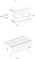
Fig. 5 shows a structural schematic diagram of thebattery cell 3 provided in some embodiments of the present application. Thebattery cell 3 refers to the smallest unit that constitutes the battery. As shown inFig. 5 , thebattery cell 3 includes a cap assembly, acasing 4, and anelectrode assembly 5. - The
electrode assembly 5 is an assembly in thebattery cell 3 that undergoes electrochemical reaction. One ormore electrode assemblies 5 may be included in thecasing 4. Theelectrode assembly 5 is mainly formed by winding or stacking the electrode plates, which are divided into a positive electrode plate and a negative electrode plate, and a separator is generally provided between the positive electrode plate and the negative electrode plate. The portions of the positive and negative electrode plates with active material form theelectrode body 51, while the portions of the positive and negative electrode plates without active material form thetabs 52 respectively. The positive and negative tabs may be located at one end of the main body together, or at two ends of the main body respectively. During the charging and discharging process of the battery, the positive and negative active materials react with the electrolyte, and thetab 52 is connected to theelectrode terminal 61 to form a current circuit. - The
casing 4 is an assembly configured to cooperate with thecap assembly 6 to form an internal environment of thebattery cell 3, wherein the formed internal environment may be configured to accommodate theelectrode assembly 5, the electrolyte (not shown in the figure), and other components. Thecasing 4 and thecap assembly 6 may be independent components, an opening may be provided on thecasing 4, and the internal environment of thebattery cell 3 may be formed by closing the opening at thecap assembly 6,. Optionally, thecap assembly 6 and thecasing 4 may also be integral. Optionally, thecap assembly 6 and thecasing 4 may firstly form a common connection face before other components enter the casing, and when the interior of thecasing 4 is required to be encapsulated, thecap assembly 6 may be then covered onto thecasing 4. Thecasing 4 may be of various shapes and sizes, such as rectangular, cylindrical, hexagonal, and the like. The shape of thecasing 4 may be determined based on the specific shape and size of theelectrode assembly 5. Various materials are available for thecasing 4, and optionally, the material ofcasing 4 may be copper, iron, aluminum, stainless steel, aluminum alloy, plastic, or the like. - In some embodiments, as shown in
Fig. 5 , twoelectrode terminals 61 may be provided in thecap assembly 6. Oneelectrode terminal 61 in thecap assembly 6 is electrically connected to one tab 52 (such as a positive tab) of theelectrode assembly 5, and theother electrode terminal 61 in thecap assembly 6 is electrically connected to the other tab 52 (such as the negative tab) of theelectrode assembly 5. - In some other embodiments, the
casing 4 may be provided with two openings. The two openings are disposed on two opposite sides of thecasing 4. Twocap assemblies 6 are provided. The twocap assemblies 6 cover the two openings of thecasing 4 respectively. In this case, theelectrode terminal 61 in thecap assembly 6 may be in number of one. Theelectrode terminal 61 in onecap assembly 6 is electrically connected to the tab 52 (such as a positive tab) of theelectrode assembly 5, and theelectrode terminal 61 in theother cap assembly 6 is electrically connected to the other tab 52 (such as the negative tab) of theelectrode assembly 5. - Please refer to
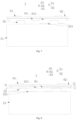
Fig. 6, and Fig. 6 shows a structural schematic diagram of thebattery cell 3 provided in an embodiment of the present application. - In some optional embodiments, as shown in
Fig. 6 , thebattery cell 3 includes acap assembly 6 and anelectrode assembly 5, thecap assembly 6 includes acap plate 62 and anisolation member 63, and theisolation member 63 is disposed on one side of thecap plate 62; theelectrode assembly 5 is disposed on a side of theisolation member 63 facing away from thecap plate 62, theelectrode assembly 5 includes anelectrode body 51 andtabs 52 protruding from theelectrode body 51, aprotrusion 521 connected with theelectrode body 51 is provided on a peripheral side of at least one of thetabs 52; wherein aclearance groove 631 is provided on a surface of theisolation member 63 facing away from thecap plate 62 and is configured to accommodate at least a portion of theprotrusion 521. - The
cap plate 62 covers the opening of thecasing 4, and the shape of thecap plate 62 may be the same as the opening of thecasing 4. Thecap plate 62 may also be of various structures, exemplarily, thecap plate 62 has a plate-like structure. Optionally, thecap plate 62 may be made of metals such as copper, iron, aluminum, stainless steel, aluminum alloy, or the like. - The
isolation member 63 is disposed on one side of thecap plate 62. Theisolation member 63 serves to fix and protect theelectrode assembly 5, as well as to insulate theelectrode assembly 5 from thecap assembly 6, preventing the problem of degradation of battery performance and short circuit caused by the displacement of theelectrode assembly 5 under the action of external force. Theisolation member 63 may be disposed on one side of thecap plate 62 through nesting, clamping, or bonding. Theisolation member 63 may be formed by injection molding, and the shape of theisolation member 63 may be disposed to match with the shape of thecap plate 62. - Optionally, the
isolation member 63 is integrally formed from polyphenyl sulfide (PPS) material, polysulfone (PSU) material, nanomaterial, or the like. PPS material, PSU material, and nanomaterial all have high temperature resistance, corrosion resistance, superior mechanical property and insulation property, which is beneficial to improve the service life of theisolation member 63, thereby improving the quality of thebattery cell 3, and making the battery cell have good environmental protection and fire prevention performance to be more aligned with environmental requirements. In actual production, the user may use PPS material, PSU material, nanomaterial, or other suitable insulation material to form theisolation member 63 according to the structure and cost requirements of thebattery cell 3. - The
protrusion 521 may be connected to any position on the peripheral side of thetab 52, for example, theprotrusion 521 is disposed at an end close to theelectrode body 51 on the peripheral side of thetab 52. Theprotrusion 521 may be disposed on anytab 52. Theprotrusion 521 is connected to thetab 52 and theelectrode body 51. Theprotrusion 521 increases the current-flowing area between thetab 52 and theelectrode body 51, improving the battery performance. - Please refer to
Fig. 7, and Fig. 7 shows a structural schematic diagram of anotherbattery cell 3 provided in an embodiment of the present application. - Optionally, as shown in
Figs. 6 and7 , theprotrusion 521 may be connected to any of thetabs 52, and theisolation member 63 is provided with aclearance groove 631 corresponding to theprotrusion 521. - Please refer to
Fig. 8, and Fig. 8 shows a structural schematic diagram of anotherbattery cell 3 provided in an embodiment of the present application. - Optionally, as shown in
Fig. 8 , each of thetabs 52 is connected with theprotrusion 521, and theisolation member 63 is provided with a plurality ofclearance grooves 631 corresponding to a plurality ofprotrusions 521. Optionally, theclearance groove 631 and theisolation member 63 are formed in the same process, simplifying the process flow. - Optionally, a thickness of the
clearance groove 631 may not be smaller than a thickness of theprotrusion 521, avoiding interference of theisolation member 63 with theprotrusion 521 under the action of external force. - In the
battery cell 3 provided in the embodiment of the present application, thecap assembly 6 includes thecap plate 62 and theisolation member 63, theisolation member 63 is disposed on one side of thecap plate 62, and theelectrode assembly 5 is disposed on a side of theisolation member 63 facing away from thecap plate 62. Theelectrode assembly 5 includes anelectrode body 51 andtabs 52 protruding from theelectrode body 51, and theprotrusion 521 connected with theelectrode body 51 is provided on a peripheral side of at least one of thetabs 52, increasing the current-flowing area between thetab 52 and theelectrode body 51. Theclearance groove 631 is provided on a surface of theisolation member 63 facing away from thecap plate 62 and accommodates at least a portion of theprotrusion 521, improving the problem of insertion of thetab 52 caused by the interference of theisolation member 63 with theprotrusion 521, improving the cooperation relationship between theisolation member 63 and thetab 52, and improving the battery performance. - In some embodiments, as shown in
Fig. 8 , at least a portion of an inner wall surface of theclearance groove 631 abuts against outer surface of theprotrusion 521. - When the
protrusion 521 tends to move under the action of external force, the inner wall surface of theclearance groove 631 abuts against the outer surface of theprotrusion 521, and theclearance groove 631 can provide greater resistance to theprotrusion 521 and improve the problem of degradation of battery performance caused by the misalignment of theprotrusion 521, such as the tilting of theprotrusion 521. - Optionally, at least a portion of the inner wall surface of the
clearance groove 631 abuts against the surface of theprotrusion 521 on a side facing away from theelectrode body 51. The area of the surface of theprotrusion 521 on a side facing away from theelectrode body 51 is the biggest, and the abutment of this surface against theclearance groove 631 can effectively ensure the fixing effect of theclearance groove 631 on theprotrusion 521 and save the cost. - In these embodiments, at least a portion of the inner wall surface of the
clearance groove 631 abuts against the outer surface of theprotrusion 521, allowing theisolation member 63 to limit the position of theprotrusion 521, and improving the problem of short circuit of the battery caused by misalignment of theprotrusion 521 under the action of external force. - In some embodiments, as shown in
Fig. 8 , in a direction from thecap plate 62 to theisolation member 63, a depth L1 of theclearance groove 631 accounts for 20% - 80% of a thickness L of theisolation member 63. - Optionally, the
clearance groove 631 penetrates through theisolation member 63, and theclearance groove 631 with this design reduces the difficulty of machining theclearance groove 631. - Optionally, in a length direction of the
isolation member 63, a length of theclearance groove 631 accounts for 15% - 35% of a length of theisolation member 63. - In these embodiments, the depth L1 of the
clearance groove 631 accounts for 20% - 80% of the thickness L of theisolation member 63, preventing theclearance groove 631 from interfering with theprotrusion 521 due to the depth L1 of theclearance groove 631 being too small, and also improving the insufficient limiting effect of theclearance groove 631 on the position of theprotrusion 521 due to the depth of theclearance groove 631 being too excessive. - In some embodiments, as shown in
Fig. 8 , in the direction from thecap plate 62 to theisolation member 63, an orthographic projection of theclearance groove 631 coincides with an orthographic projection of theprotrusion 521. - The
clearance groove 631 abuts against the surface of theprotrusion 521 facing away from the electrode body, and meanwhile, the orthographic projection of theclearance groove 631 coincides with the orthographic projection of theprotrusion 521, and theclearance groove 631 also abuts fully against a side surface of theprotrusion 521. At this time, the contact area between theclearance groove 631 and theprotrusion 521 is the largest, and theclearance groove 631 provides the greatest resistance to theprotrusion 521. - In these embodiments, the orthographic projection of the
clearance groove 631 coincides with the orthographic projection of theprotrusion 521, and the outer surface of theprotrusion 521 abuts fully against theclearance groove 631. Thus, theclearance groove 631 provides the greatest resistance to theprotrusion 521, and theclearance groove 631 has a greater limiting effect on the position of theprotrusion 521. - Please refer to
Figs. 9 and 10 , in whichFig. 9 shows a structural schematic diagram of another battery cell provided in an embodiment of the present application, andFig. 10 shows a structural schematic diagram of an isolation member of another battery cell provided in an embodiment of the present application. - In some embodiments, as shown in
Figs. 9 and 10 , two ormore clearance grooves 631 spaced apart along the first direction X are provided on the side of theisolation member 63 facing away from thecap plate 62; theelectrode assembly 5 is provided with two ormore protrusions 521 spaced apart along the first direction, and each of theprotrusions 521 is correspondingly located in each of theclearance grooves 631. Alternatively, theelectrode body 51 is provided with oneprotrusion 521, and the oneprotrusion 521 is located in one of theclearance grooves 631. - Optionally, the first direction is the X direction, and the second direction is the Y direction.
- Two or
more clearance grooves 631 spaced apart along the first direction X are provided on the side of theisolation member 63 facing away from thecap plate 62, theprotrusion 521 is located in theclearance groove 631, in a thickness direction of theprotrusion 521, the orthographic projection of theprotrusion 521 is located within the orthographic projection of theclearance groove 631, and theclearance groove 631 may fully accommodate theprotrusion 521. Therefore, in the production and manufacturing process, theisolation member 63 provided with theclearance groove 631 may be produced separately and matched with theelectrode assembly 5 withvarious protrusions 521 of different shapes and sizes, saving the cost. - Optionally, the
clearance grooves 631 spaced apart are of same size and shape, facilitating production and improving production efficiency. - Optionally, an
elastic member 632 is disposed in theclearance groove 631, and theelastic member 632 is reciprocally deformable in a depth direction of theclearance groove 631, allowing thatvarious protrusions 521 of different thicknesses may be configured in theclearance groove 631, improving the compatibility of theisolation member 63. Theelastic member 632 may be made of insulating material, and a stiffness of theelastic member 632 is smaller than that of theisolation member 63, reducing the interference degree of theelastic member 632 with theprotrusion 521. Meantime, theelastic member 632 may abut against theprotrusion 521, functioning to limit the position of theprotrusion 521. - Optionally, the
elastic member 632 may be a buffer layer, a spring, a three-dimensional mesh filler, an elastic plate, or the like made of insulating polymer material. - In these embodiments, two or
more clearance grooves 631 spaced apart along the first direction X are provided on the side of theisolation member 63 facing away from thecap plate 62; theelectrode assembly 5 is provided with two ormore protrusions 521 spaced apart along the first direction X, and each of theprotrusions 521 is correspondingly located in each of theclearance grooves 631. Alternatively, theelectrode body 51 is provided with oneprotrusion 521, and the oneprotrusion 521 is located in one of theclearance grooves 631. With such an arrangement, theclearance groove 631 disposed in this way may be compatible withvarious protrusions 521, improving the compatibility of theisolation member 63. - In some embodiments, as shown in
Figs. 9 and 10 , a distance L2 between the twoclearance grooves 631 in the first direction X is at least 20% of the length of thecap assembly 6. - Optionally, in the second direction Y, a width L3 of the
clearance groove 631 may not exceed 90% of a width L4 of theisolation member 63. - In these embodiments, the distance L2 between the two
clearance grooves 631 is at least 20% of the length of thecap assembly 6, preventing a short circuit in the battery due to theelectrode body 51 being misaligned, which is caused by the distance between the twoclearance grooves 631 being too small and the fixing capacity of theisolation member 63 on theelectrode body 51 being insufficient. - In some embodiments, as shown in
Figs. 9 and 10 , the twoclearance grooves 631 are symmetrically disposed relative to an axis extending along the second direction Y, and the first direction X intersects with the second direction Y - Optionally, the two
clearance grooves 631 are of same shape and size. - In these embodiments, the symmetrically disposed
clearance groove 631 has low machining difficulty and is convenient for manufacturing. - In some embodiments, as shown in
Figs. 9 and 10 , theisolation member 63 further includes aliquid injection hole 633 disposed to be penetrated, and theliquid injection hole 633 is staggered with theclearance groove 631. - The
liquid injection hole 633 is a small hole that penetrates through thecap plate 62 and theisolation member 63, and is configured to fill the electrolyte into theelectrode assembly 5. - In these embodiments, the
liquid injection hole 633 is staggered with theclearance groove 631, preventing theprotrusion 521 from blocking theliquid injection hole 633. - In some embodiments, as shown in
Figs. 9 and 10 , theisolation member 63 is provided with anabutment portion 635 protruding toward theelectrode assembly 5, and theabutment portion 635 is configured to abut against theelectrode body 51, and theclearance groove 631 is disposed at theabutment portion 635. - In these embodiments, the
isolation member 63 includes anabutment portion 635 protruding toward theelectrode assembly 5, and theabutment portion 635 abuts against theelectrode body 51, improving the problem of short circuit in the battery caused by misalignment of theelectrode body 5 under the action of external force. - Please refer to
Fig. 11, and Fig. 11 shows a structural schematic diagram of anotherbattery cell 3 provided in an embodiment of the present application. - In some embodiments, as shown in
Fig. 11 , the battery cell further includes aconnector 64, which is connected to thetab 52, and theconnector 64 is staggered with theclearance groove 631. - The
connector 64 is disposed between thetab 52 and thecap assembly 6, ensuring that thetab 52 and thecap assembly 6 may be connected through theconnector 64 when thetab 52 cannot be directly aligned with theelectrode terminal 61. - Since the
protrusion 521 is disposed at an end of thetab 52 close to theelectrode body 51 and the thickness of theprotrusion 521 is smaller than that of thetab 52, after a portion of theconnector 64 enters theclearance groove 631, theconnector 64 will create a gap between the surface of theclearance groove 631 and theprotrusion 521, reducing the limiting effect of theclearance groove 631 on the position of theprotrusion 521. - Optionally, the
connector 64 may be made of metal such as copper, iron, aluminum, stainless steel, aluminum alloy, or the like. - In these embodiments, the
connector 64 is connected to thetab 52, and theconnector 64 is staggered with theclearance groove 631, preventing the possibility of theclearance groove 631 not being able to abut against theprotrusion 521 due to a portion of theconnector 64 entering theclearance groove 631, and reducing the limiting effect of theisolation member 63 on the position of thetab 521. - Please refer to
Fig. 12, and Fig. 12 shows a structural schematic diagram of anotherbattery cell 3 provided in an embodiment of the present application. - In some embodiments, as shown in
Fig. 12 , the battery cell further includes aconnector 64, which is connected to theprotrusion 521, and at least a portion of theconnector 64 is located in theclearance groove 631. - Optionally, the depth of the
clearance groove 631 may not be less than a sum of the thickness of theconnector 64 and the thickness of theprotrusion 521. - In these embodiments, the
connector 64 is connected to theprotrusion 521, and at least a portion of theconnector 64 is located in theclearance groove 631, ensuring that theisolation member 63 does not interfere with theprotrusion 521 via theconnector 64. - In some embodiments, as shown in
Fig. 12 , theclearance groove 631 is disposed between twoadjacent tabs 52 in the first direction X. - Generally, most of the
protrusions 521 are disposed between twotabs 52 adjacent in the first direction X, and only a small portion of theprotrusion 521 is disposed at a portion outside the twotabs 52 adjacent in the first direction X. Due to the extremely small extending distance of the portion ofprotrusion 521 located outside the twotabs 52 in the first direction X, this portion of theprotrusion 521 is subjected to less pressure from theisolation member 63, and meantime, due to the short torque, this portion of theprotrusion 521 has a relatively high ability to resist deformation. Moreover, the difficulty in manufacturing theclearance groove 631 that corresponds to this portion of theprotrusion 521 is relatively high, resulting in half the effort, and thus, theclearance groove 631 is disposed between twotabs 52 adjacent in the first direction. - In these embodiments, the
clearance groove 631 is disposed between twotabs 52 adjacent in the first direction X, reducing process difficulty and saving the cost. - Please refer to
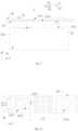
Figs. 13 and 14 , in whichFig. 13 shows a structural schematic diagram of thecap plate 62 of thebattery cell 3 provided in an embodiment of the present application, andFig. 14 shows a structural schematic diagram of theisolation member 63 of thebattery cell 3 provided in an embodiment of the present application. - In some embodiments, as shown in
Figs. 12 to 14 , the battery cell further includes an explosionproof valve hole 65 that penetrates through thecap plate 62; theisolation member 63 is provided with avent hole 634 in communication with the explosionproof valve hole 65, and thevent hole 634 is staggered with theclearance groove 631. - The explosion proof valve is configured to release the pressure inside
battery cell 3 when the internal pressure or temperature ofbattery cell 3 reaches a threshold. - Optionally, the explosion proof valve is disposed in the middle of the
cap plate 62. - The
isolation member 63 is provided with avent hole 634, which is configured to discharge gas from thebattery cell 3. - Optionally, in the thickness direction of the
isolation member 63, the orthogonal projection of at least a portion of thevent hole 634 coincide with the orthogonal projection of the explosion proof valve hole 651. - Optionally, the
vent hole 634 is disposed in the middle of theisolation member 63. - Optionally, a plurality of the vent holes 634 are distributed on the
isolation member 63 in rows and columns along the first direction X and the second direction Y - In some embodiments, the
isolation member 63 is provided with thevent hole 634 in communication with the explosionproof valve hole 65, and the explosion proof valve will not affect the breathability of thevent hole 634; thevent hole 634 is staggered with theclearance groove 631, preventing the protrusion from affecting the gas exhaust ofelectrode assembly 5 through thevent hole 634. - An embodiment of the present application also provides a battery, including the battery cell provided in the above embodiments.
- The battery provided in the embodiment of the present application has the same technical effect due to the use of the battery cell provided in the above embodiments, and will not be further described here.
- An embodiment of the present application also provides an electricity consuming apparatus, including the battery provided in the above embodiment, and the battery is configured to provide electrical energy.
- The electricity consuming apparatus provided in the embodiment of the present application has the same technical effect due to the use of the battery provided in the embodiment of the present application, and will not be further described here.
- Please refer to
Figs. 2 to 14 , according to some embodiments of the present application, the present application provides thebattery cell 3 including thecap assembly 6 and theelectrode assembly 5, thecap assembly 6 includes thecap plate 62 and theisolation member 63, and theisolation member 63 is disposed on one side of thecap plate 62. - The
electrode assembly 5 is disposed on the side of theisolation member 63 facing away from thecap plate 62, theelectrode assembly 5 includes theelectrode body 51 andtabs 52 protruding from theelectrode body 51, and theprotrusion 521 connected with theelectrode body 51 is disposed on the peripheral side of at least one of thetabs 52. - The
clearance groove 631 is provided on the surface of theisolation member 63 facing away from thecap plate 62, theclearance groove 631 is disposed between twotabs 52 adjacent in the first direction, and theclearance groove 631 is configured to accommodate theprotrusion 521; the inner wall surface of theclearance groove 631 abuts against the outer surface of theprotrusion 521, and in the direction from thecap plate 62 to theisolation member 63, the orthographic projection of theclearance groove 631 coincides with the orthographic projection of theprotrusion 521. - The
isolation member 63 further includes theliquid injection hole 633 disposed to be penetrated, and theliquid injection hole 633 is staggered with theclearance groove 631; theconnector 64 is connected to thetab 52, and theconnector 64 is staggered with theclearance groove 631; theisolation member 63 is provided with avent hole 634 in communication with the explosionproof valve hole 65, and thevent hole 634 is staggered with theclearance groove 631. - In these embodiments, the
cap assembly 6 includes thecap plate 62 and theisolation member 63, and theisolation member 63 is disposed on one side of thecap plate 62; the electrode terminal 61is disposed on the side of theisolation member 63 facing away from thecap plate 62, and the electrode terminal 61includes theelectrode body 51 andtabs 52 protruding from theelectrode body 51, theprotrusion 521 connected with theelectrode body 51 is disposed on the peripheral side of at least one of thetabs 52, increasing the current-flowing area between thetab 52 and theelectrode body 51; theclearance groove 631 is provided on the surface of theisolation member 63 facing away from thecap plate 62, and theclearance groove 631 accommodates at least a portion of theprotrusion 521, improving the problem of insertion of thetab 52 caused by the interference of theisolation member 63 with theprotrusion 521, improving the cooperation relationship between theisolation member 63 and thetab 52, and improving battery performance. - Although the present application has been described with reference to the preferred embodiments, various modifications may be made thereto and equivalents may be substituted for parts thereof without departing from the scope of the present application. In particular, as long as there are no structural conflicts, the technical features mentioned in each of the embodiments can be combined in any way. The present application is not limited to the specific embodiments disclosed herein, but includes all technical solutions falling within the scope of the claims.
Claims (15)
- A battery cell, comprising:a cap assembly, comprising a cap plate and an isolation member, the isolation member being disposed on one side of the cap plate; andan electrode assembly, disposed on a side of the isolation member facing away from the cap plate, the electrode assembly comprising an electrode body and tabs protruding from the electrode body, a protrusion connected with the electrode body being connected on a peripheral side of at least one of the tabs;wherein a clearance groove is provided on a surface of the isolation member facing away from the cap plate, and is configured to accommodate at least a portion of the protrusion.
- The battery cell as claimed in claim 1, wherein at least a portion of an inner wall surface of the clearance groove abuts against an outer surface of the protrusion.
- The battery cell as claimed in claim 2, wherein in a direction from the cap plate to the isolation member, a depth L1 of the clearance groove accounts for 20% - 80% of a thickness L of the isolation member.
- The battery cell as claimed in claim 2 or 3, wherein in a direction from the cap plate to the isolation member, an orthographic projection of the clearance groove coincides with an orthographic projection of the protrusion.
- The battery cell as claimed in claim 2, wherein two or more clearance grooves spaced apart in a first direction are provided on the side of the isolation member facing away from the cap plate; and
the electrode assembly is provided with two or more protrusions spaced apart in the first direction, each of the protrusions is located correspondingly in each of the clearance grooves; or the electrode assembly is provided with one protrusion, and the one protrusion is located in one of the clearance grooves. - The battery cell as claimed in claim 5, wherein a distance between the two clearance grooves in the first direction is at least 20% of a length of the cap assembly.
- The battery cell as claimed in claim 5 or 6, wherein the two clearance grooves are symmetrically disposed relative to an axis extending in a second direction, and the first direction intersects with the second direction.
- The battery cell as claimed in any one of claims 1 to 7, wherein the isolation member is provided with an abutment portion protruding toward the electrode assembly, the abutment portion is configured to abut against the electrode body, and the clearance groove is disposed at the abutment portion.
- The battery cell as claimed in any one of claims 1 to 8, wherein the isolation member further comprises a liquid injection hole disposed to be penetrated, and the liquid injection hole is staggered with the clearance groove.
- The battery cell as claimed in any one of claims 1 to 9, further comprising a connector, which is connected to the tab and is staggered with the clearance groove.
- The battery cell as claimed in any one of claims 1 to 9, further comprising a connector, which is connected to the protrusion, and at least a portion of the connector being located in the clearance groove.
- The battery cell as claimed in claim 5, wherein the clearance groove is disposed between two tabs adjacent in the first direction.
- The battery cell as claimed in any one of claims 1 to 12, further comprising an explosion proof valve hole penetrating through the cap plate, wherein
the isolation member is provided with a vent hole in communication with the explosion proof valve hole, and the vent hole is staggered with the clearance groove. - A battery, comprising the battery cell as claimed in any one of claims 1 to 13.
- An electricity consuming apparatus, comprising the battery as claimed in claim 14, the battery being configured to supply electric power.
Applications Claiming Priority (2)
| Application Number | Priority Date | Filing Date | Title |
|---|---|---|---|
| CN202221624387.4U CN217562788U (en) | 2022-06-28 | 2022-06-28 | Battery cell, battery and power consumption device |
| PCT/CN2022/115560 WO2024000785A1 (en) | 2022-06-28 | 2022-08-29 | Battery cell, battery, and electric device |
Publications (2)
| Publication Number | Publication Date |
|---|---|
| EP4395060A1 true EP4395060A1 (en) | 2024-07-03 |
| EP4395060A4 EP4395060A4 (en) | 2025-06-18 |
Family
ID=83503271
Family Applications (1)
| Application Number | Title | Priority Date | Filing Date |
|---|---|---|---|
| EP22948875.4A Pending EP4395060A4 (en) | 2022-06-28 | 2022-08-29 | BATTERY CELL, BATTERY AND ELECTRICAL DEVICE |
Country Status (4)
| Country | Link |
|---|---|
| US (1) | US20240258665A1 (en) |
| EP (1) | EP4395060A4 (en) |
| CN (1) | CN217562788U (en) |
| WO (1) | WO2024000785A1 (en) |
Families Citing this family (3)
| Publication number | Priority date | Publication date | Assignee | Title |
|---|---|---|---|---|
| EP4478527A4 (en) * | 2022-10-27 | 2025-10-29 | Contemporary Amperex Technology Hong Kong Ltd | BATTERY CELL, BATTERY AND ELECTRICAL DEVICE |
| CN116031548B (en) | 2023-02-09 | 2023-06-27 | 深圳海润新能源科技有限公司 | End cover assembly, energy storage device and electric equipment |
| CN119905738B (en) * | 2025-01-21 | 2025-12-02 | 蜂巢能源科技股份有限公司 | Battery case and battery |
Family Cites Families (8)
| Publication number | Priority date | Publication date | Assignee | Title |
|---|---|---|---|---|
| JP4289738B2 (en) * | 1998-10-30 | 2009-07-01 | 三洋電機株式会社 | Sealed battery |
| KR101022634B1 (en) * | 2006-02-20 | 2011-03-22 | 주식회사 엘지화학 | Cap assembly of improved structure and secondary battery comprising the same |
| KR101265199B1 (en) * | 2011-08-08 | 2013-05-23 | 삼성에스디아이 주식회사 | Rechargeable battery |
| JP2014107147A (en) * | 2012-11-28 | 2014-06-09 | Toyota Industries Corp | Electricity storage device |
| KR102324345B1 (en) * | 2015-01-28 | 2021-11-10 | 삼성에스디아이 주식회사 | secondary battery |
| CN210743995U (en) * | 2019-11-06 | 2020-06-12 | 宁德时代新能源科技股份有限公司 | Battery cell, battery module, battery pack and device |
| CN213583958U (en) * | 2020-12-14 | 2021-06-29 | 凯博能源科技有限公司 | Battery cover plate assembly and battery with same |
| CN214672774U (en) * | 2021-06-07 | 2021-11-09 | 凤凰新能源(惠州)有限公司 | Top cover structure of high-rate battery |
-
2022
- 2022-06-28 CN CN202221624387.4U patent/CN217562788U/en active Active
- 2022-08-29 WO PCT/CN2022/115560 patent/WO2024000785A1/en not_active Ceased
- 2022-08-29 EP EP22948875.4A patent/EP4395060A4/en active Pending
-
2024
- 2024-04-12 US US18/634,189 patent/US20240258665A1/en active Pending
Also Published As
| Publication number | Publication date |
|---|---|
| EP4395060A4 (en) | 2025-06-18 |
| CN217562788U (en) | 2022-10-11 |
| WO2024000785A1 (en) | 2024-01-04 |
| US20240258665A1 (en) | 2024-08-01 |
Similar Documents
| Publication | Publication Date | Title |
|---|---|---|
| US20250015426A1 (en) | Housing, battery cell, battery, and power consuming device | |
| US20240258665A1 (en) | Battery cell, battery and electricity consuming apparatus | |
| US11757161B2 (en) | Battery cell, battery and electricity consuming device | |
| CN216903136U (en) | Battery cells, batteries and electrical equipment | |
| US20250055063A1 (en) | Thermal management assembly, battery, and electric apparatus | |
| US20240243450A1 (en) | Adapter assembly, battery cell, battery, and electrical device | |
| US20250015466A1 (en) | End cover assembly, battery cell and battery | |
| US20230369711A1 (en) | End cap, battery cell, battery and power consuming device | |
| US20250079651A1 (en) | Battery Cell, Battery and Electrical Equipment | |
| US20240413495A1 (en) | Battery cell, battery, electric device, and manufacturing method | |
| CN222126913U (en) | Connecting element, battery cell, battery and consumer | |
| US20260018690A1 (en) | High-voltage box, battery, and electrical device | |
| EP4475295A1 (en) | End cover assembly, cell, battery and electrical device | |
| CN118696426A (en) | Electrode assembly, preparation method, battery cell, battery and electrical device | |
| EP4280354A1 (en) | Battery case, battery, electric device, and method and device for preparing battery | |
| US20240347824A1 (en) | End cover assembly, battery cell, battery, and electrical device | |
| CN217562770U (en) | Battery cell, battery and power consumption device | |
| CN216850096U (en) | Battery cell, battery and power consumption device | |
| CN222867820U (en) | End cap assembly, battery cell, battery and electrical device | |
| CN222365642U (en) | Battery cell, battery and electricity utilization device | |
| CN222637462U (en) | Battery box, battery and power consumption device | |
| CN222601186U (en) | Battery box, battery and power utilization device | |
| CN223771297U (en) | Battery cell, battery device and electricity utilization device | |
| CN223967342U (en) | Battery cell, battery device and electricity utilization device | |
| EP4503256A1 (en) | Battery cell, battery, and electric device |
Legal Events
| Date | Code | Title | Description |
|---|---|---|---|
| STAA | Information on the status of an ep patent application or granted ep patent |
Free format text: STATUS: THE INTERNATIONAL PUBLICATION HAS BEEN MADE |
|
| PUAI | Public reference made under article 153(3) epc to a published international application that has entered the european phase |
Free format text: ORIGINAL CODE: 0009012 |
|
| STAA | Information on the status of an ep patent application or granted ep patent |
Free format text: STATUS: REQUEST FOR EXAMINATION WAS MADE |
|
| 17P | Request for examination filed |
Effective date: 20240327 |
|
| AK | Designated contracting states |
Kind code of ref document: A1 Designated state(s): AL AT BE BG CH CY CZ DE DK EE ES FI FR GB GR HR HU IE IS IT LI LT LU LV MC MK MT NL NO PL PT RO RS SE SI SK SM TR |
|
| RAP1 | Party data changed (applicant data changed or rights of an application transferred) |
Owner name: CONTEMPORARY AMPEREX TECHNOLOGY(HONG KONG) LIMITED |
|
| REG | Reference to a national code |
Ref country code: DE Ref legal event code: R079 Free format text: PREVIOUS MAIN CLASS: H01M0050597000 Ipc: H01M0050150000 |
|
| A4 | Supplementary search report drawn up and despatched |
Effective date: 20250519 |
|
| RIC1 | Information provided on ipc code assigned before grant |
Ipc: H01M 50/627 20210101ALI20250513BHEP Ipc: H01M 50/593 20210101ALI20250513BHEP Ipc: H01M 50/586 20210101ALI20250513BHEP Ipc: H01M 50/533 20210101ALI20250513BHEP Ipc: H01M 50/528 20210101ALI20250513BHEP Ipc: H01M 50/15 20210101AFI20250513BHEP |
|
| DAV | Request for validation of the european patent (deleted) | ||
| DAX | Request for extension of the european patent (deleted) | ||
| STAA | Information on the status of an ep patent application or granted ep patent |
Free format text: STATUS: EXAMINATION IS IN PROGRESS |
|
| 17Q | First examination report despatched |
Effective date: 20251219 |