EP4395040A1 - Battery pack and vehicle including same - Google Patents
Battery pack and vehicle including same Download PDFInfo
- Publication number
- EP4395040A1 EP4395040A1 EP23860716.2A EP23860716A EP4395040A1 EP 4395040 A1 EP4395040 A1 EP 4395040A1 EP 23860716 A EP23860716 A EP 23860716A EP 4395040 A1 EP4395040 A1 EP 4395040A1
- Authority
- EP
- European Patent Office
- Prior art keywords
- cell
- battery
- battery pack
- cover
- Prior art date
- Legal status (The legal status is an assumption and is not a legal conclusion. Google has not performed a legal analysis and makes no representation as to the accuracy of the status listed.)
- Pending
Links
Images




Classifications
-
- H—ELECTRICITY
- H01—ELECTRIC ELEMENTS
- H01M—PROCESSES OR MEANS, e.g. BATTERIES, FOR THE DIRECT CONVERSION OF CHEMICAL ENERGY INTO ELECTRICAL ENERGY
- H01M50/00—Constructional details or processes of manufacture of the non-active parts of electrochemical cells other than fuel cells, e.g. hybrid cells
- H01M50/30—Arrangements for facilitating escape of gases
- H01M50/383—Flame arresting or ignition-preventing means
-
- H—ELECTRICITY
- H01—ELECTRIC ELEMENTS
- H01M—PROCESSES OR MEANS, e.g. BATTERIES, FOR THE DIRECT CONVERSION OF CHEMICAL ENERGY INTO ELECTRICAL ENERGY
- H01M50/00—Constructional details or processes of manufacture of the non-active parts of electrochemical cells other than fuel cells, e.g. hybrid cells
- H01M50/30—Arrangements for facilitating escape of gases
- H01M50/35—Gas exhaust passages comprising elongated, tortuous or labyrinth-shaped exhaust passages
- H01M50/367—Internal gas exhaust passages forming part of the battery cover or case; Double cover vent systems
-
- H—ELECTRICITY
- H01—ELECTRIC ELEMENTS
- H01M—PROCESSES OR MEANS, e.g. BATTERIES, FOR THE DIRECT CONVERSION OF CHEMICAL ENERGY INTO ELECTRICAL ENERGY
- H01M10/00—Secondary cells; Manufacture thereof
- H01M10/60—Heating or cooling; Temperature control
- H01M10/61—Types of temperature control
- H01M10/613—Cooling or keeping cold
-
- H—ELECTRICITY
- H01—ELECTRIC ELEMENTS
- H01M—PROCESSES OR MEANS, e.g. BATTERIES, FOR THE DIRECT CONVERSION OF CHEMICAL ENERGY INTO ELECTRICAL ENERGY
- H01M10/00—Secondary cells; Manufacture thereof
- H01M10/60—Heating or cooling; Temperature control
- H01M10/62—Heating or cooling; Temperature control specially adapted for specific applications
- H01M10/625—Vehicles
-
- H—ELECTRICITY
- H01—ELECTRIC ELEMENTS
- H01M—PROCESSES OR MEANS, e.g. BATTERIES, FOR THE DIRECT CONVERSION OF CHEMICAL ENERGY INTO ELECTRICAL ENERGY
- H01M10/00—Secondary cells; Manufacture thereof
- H01M10/60—Heating or cooling; Temperature control
- H01M10/64—Heating or cooling; Temperature control characterised by the shape of the cells
- H01M10/647—Prismatic or flat cells, e.g. pouch cells
-
- H—ELECTRICITY
- H01—ELECTRIC ELEMENTS
- H01M—PROCESSES OR MEANS, e.g. BATTERIES, FOR THE DIRECT CONVERSION OF CHEMICAL ENERGY INTO ELECTRICAL ENERGY
- H01M10/00—Secondary cells; Manufacture thereof
- H01M10/60—Heating or cooling; Temperature control
- H01M10/65—Means for temperature control structurally associated with the cells
- H01M10/653—Means for temperature control structurally associated with the cells characterised by electrically insulating or thermally conductive materials
-
- H—ELECTRICITY
- H01—ELECTRIC ELEMENTS
- H01M—PROCESSES OR MEANS, e.g. BATTERIES, FOR THE DIRECT CONVERSION OF CHEMICAL ENERGY INTO ELECTRICAL ENERGY
- H01M10/00—Secondary cells; Manufacture thereof
- H01M10/60—Heating or cooling; Temperature control
- H01M10/65—Means for temperature control structurally associated with the cells
- H01M10/655—Solid structures for heat exchange or heat conduction
- H01M10/6551—Surfaces specially adapted for heat dissipation or radiation, e.g. fins or coatings
-
- H—ELECTRICITY
- H01—ELECTRIC ELEMENTS
- H01M—PROCESSES OR MEANS, e.g. BATTERIES, FOR THE DIRECT CONVERSION OF CHEMICAL ENERGY INTO ELECTRICAL ENERGY
- H01M10/00—Secondary cells; Manufacture thereof
- H01M10/60—Heating or cooling; Temperature control
- H01M10/65—Means for temperature control structurally associated with the cells
- H01M10/655—Solid structures for heat exchange or heat conduction
- H01M10/6554—Rods or plates
-
- H—ELECTRICITY
- H01—ELECTRIC ELEMENTS
- H01M—PROCESSES OR MEANS, e.g. BATTERIES, FOR THE DIRECT CONVERSION OF CHEMICAL ENERGY INTO ELECTRICAL ENERGY
- H01M10/00—Secondary cells; Manufacture thereof
- H01M10/60—Heating or cooling; Temperature control
- H01M10/65—Means for temperature control structurally associated with the cells
- H01M10/655—Solid structures for heat exchange or heat conduction
- H01M10/6556—Solid parts with flow channel passages or pipes for heat exchange
-
- H—ELECTRICITY
- H01—ELECTRIC ELEMENTS
- H01M—PROCESSES OR MEANS, e.g. BATTERIES, FOR THE DIRECT CONVERSION OF CHEMICAL ENERGY INTO ELECTRICAL ENERGY
- H01M50/00—Constructional details or processes of manufacture of the non-active parts of electrochemical cells other than fuel cells, e.g. hybrid cells
- H01M50/10—Primary casings; Jackets or wrappings
- H01M50/102—Primary casings; Jackets or wrappings characterised by their shape or physical structure
- H01M50/105—Pouches or flexible bags
-
- H—ELECTRICITY
- H01—ELECTRIC ELEMENTS
- H01M—PROCESSES OR MEANS, e.g. BATTERIES, FOR THE DIRECT CONVERSION OF CHEMICAL ENERGY INTO ELECTRICAL ENERGY
- H01M50/00—Constructional details or processes of manufacture of the non-active parts of electrochemical cells other than fuel cells, e.g. hybrid cells
- H01M50/10—Primary casings; Jackets or wrappings
- H01M50/172—Arrangements of electric connectors penetrating the casing
- H01M50/174—Arrangements of electric connectors penetrating the casing adapted for the shape of the cells
- H01M50/178—Arrangements of electric connectors penetrating the casing adapted for the shape of the cells for pouch or flexible bag cells
-
- H—ELECTRICITY
- H01—ELECTRIC ELEMENTS
- H01M—PROCESSES OR MEANS, e.g. BATTERIES, FOR THE DIRECT CONVERSION OF CHEMICAL ENERGY INTO ELECTRICAL ENERGY
- H01M50/00—Constructional details or processes of manufacture of the non-active parts of electrochemical cells other than fuel cells, e.g. hybrid cells
- H01M50/20—Mountings; Secondary casings or frames; Racks, modules or packs; Suspension devices; Shock absorbers; Transport or carrying devices; Holders
- H01M50/204—Racks, modules or packs for multiple batteries or multiple cells
- H01M50/207—Racks, modules or packs for multiple batteries or multiple cells characterised by their shape
- H01M50/211—Racks, modules or packs for multiple batteries or multiple cells characterised by their shape adapted for pouch cells
-
- H—ELECTRICITY
- H01—ELECTRIC ELEMENTS
- H01M—PROCESSES OR MEANS, e.g. BATTERIES, FOR THE DIRECT CONVERSION OF CHEMICAL ENERGY INTO ELECTRICAL ENERGY
- H01M50/00—Constructional details or processes of manufacture of the non-active parts of electrochemical cells other than fuel cells, e.g. hybrid cells
- H01M50/20—Mountings; Secondary casings or frames; Racks, modules or packs; Suspension devices; Shock absorbers; Transport or carrying devices; Holders
- H01M50/249—Mountings; Secondary casings or frames; Racks, modules or packs; Suspension devices; Shock absorbers; Transport or carrying devices; Holders specially adapted for aircraft or vehicles, e.g. cars or trains
-
- H—ELECTRICITY
- H01—ELECTRIC ELEMENTS
- H01M—PROCESSES OR MEANS, e.g. BATTERIES, FOR THE DIRECT CONVERSION OF CHEMICAL ENERGY INTO ELECTRICAL ENERGY
- H01M50/00—Constructional details or processes of manufacture of the non-active parts of electrochemical cells other than fuel cells, e.g. hybrid cells
- H01M50/20—Mountings; Secondary casings or frames; Racks, modules or packs; Suspension devices; Shock absorbers; Transport or carrying devices; Holders
- H01M50/271—Lids or covers for the racks or secondary casings
-
- H—ELECTRICITY
- H01—ELECTRIC ELEMENTS
- H01M—PROCESSES OR MEANS, e.g. BATTERIES, FOR THE DIRECT CONVERSION OF CHEMICAL ENERGY INTO ELECTRICAL ENERGY
- H01M50/00—Constructional details or processes of manufacture of the non-active parts of electrochemical cells other than fuel cells, e.g. hybrid cells
- H01M50/30—Arrangements for facilitating escape of gases
- H01M50/342—Non-re-sealable arrangements
-
- H—ELECTRICITY
- H01—ELECTRIC ELEMENTS
- H01M—PROCESSES OR MEANS, e.g. BATTERIES, FOR THE DIRECT CONVERSION OF CHEMICAL ENERGY INTO ELECTRICAL ENERGY
- H01M50/00—Constructional details or processes of manufacture of the non-active parts of electrochemical cells other than fuel cells, e.g. hybrid cells
- H01M50/30—Arrangements for facilitating escape of gases
- H01M50/342—Non-re-sealable arrangements
- H01M50/3425—Non-re-sealable arrangements in the form of rupturable membranes or weakened parts, e.g. pierced with the aid of a sharp member
-
- H—ELECTRICITY
- H01—ELECTRIC ELEMENTS
- H01M—PROCESSES OR MEANS, e.g. BATTERIES, FOR THE DIRECT CONVERSION OF CHEMICAL ENERGY INTO ELECTRICAL ENERGY
- H01M50/00—Constructional details or processes of manufacture of the non-active parts of electrochemical cells other than fuel cells, e.g. hybrid cells
- H01M50/30—Arrangements for facilitating escape of gases
- H01M50/35—Gas exhaust passages comprising elongated, tortuous or labyrinth-shaped exhaust passages
- H01M50/358—External gas exhaust passages located on the battery cover or case
-
- H—ELECTRICITY
- H01—ELECTRIC ELEMENTS
- H01M—PROCESSES OR MEANS, e.g. BATTERIES, FOR THE DIRECT CONVERSION OF CHEMICAL ENERGY INTO ELECTRICAL ENERGY
- H01M50/00—Constructional details or processes of manufacture of the non-active parts of electrochemical cells other than fuel cells, e.g. hybrid cells
- H01M50/50—Current conducting connections for cells or batteries
- H01M50/502—Interconnectors for connecting terminals of adjacent batteries; Interconnectors for connecting cells outside a battery casing
-
- H—ELECTRICITY
- H01—ELECTRIC ELEMENTS
- H01M—PROCESSES OR MEANS, e.g. BATTERIES, FOR THE DIRECT CONVERSION OF CHEMICAL ENERGY INTO ELECTRICAL ENERGY
- H01M50/00—Constructional details or processes of manufacture of the non-active parts of electrochemical cells other than fuel cells, e.g. hybrid cells
- H01M50/50—Current conducting connections for cells or batteries
- H01M50/502—Interconnectors for connecting terminals of adjacent batteries; Interconnectors for connecting cells outside a battery casing
- H01M50/507—Interconnectors for connecting terminals of adjacent batteries; Interconnectors for connecting cells outside a battery casing comprising an arrangement of two or more busbars within a container structure, e.g. busbar modules
-
- B—PERFORMING OPERATIONS; TRANSPORTING
- B60—VEHICLES IN GENERAL
- B60R—VEHICLES, VEHICLE FITTINGS, OR VEHICLE PARTS, NOT OTHERWISE PROVIDED FOR
- B60R16/00—Electric or fluid circuits specially adapted for vehicles and not otherwise provided for; Arrangement of elements of electric or fluid circuits specially adapted for vehicles and not otherwise provided for
- B60R16/02—Electric or fluid circuits specially adapted for vehicles and not otherwise provided for; Arrangement of elements of electric or fluid circuits specially adapted for vehicles and not otherwise provided for electric constitutive elements
- B60R16/03—Electric or fluid circuits specially adapted for vehicles and not otherwise provided for; Arrangement of elements of electric or fluid circuits specially adapted for vehicles and not otherwise provided for electric constitutive elements for supply of electrical power to vehicle subsystems or for
- B60R16/033—Electric or fluid circuits specially adapted for vehicles and not otherwise provided for; Arrangement of elements of electric or fluid circuits specially adapted for vehicles and not otherwise provided for electric constitutive elements for supply of electrical power to vehicle subsystems or for characterised by the use of electrical cells or batteries
-
- H—ELECTRICITY
- H01—ELECTRIC ELEMENTS
- H01M—PROCESSES OR MEANS, e.g. BATTERIES, FOR THE DIRECT CONVERSION OF CHEMICAL ENERGY INTO ELECTRICAL ENERGY
- H01M2220/00—Batteries for particular applications
- H01M2220/20—Batteries in motive systems, e.g. vehicle, ship, plane
-
- Y—GENERAL TAGGING OF NEW TECHNOLOGICAL DEVELOPMENTS; GENERAL TAGGING OF CROSS-SECTIONAL TECHNOLOGIES SPANNING OVER SEVERAL SECTIONS OF THE IPC; TECHNICAL SUBJECTS COVERED BY FORMER USPC CROSS-REFERENCE ART COLLECTIONS [XRACs] AND DIGESTS
- Y02—TECHNOLOGIES OR APPLICATIONS FOR MITIGATION OR ADAPTATION AGAINST CLIMATE CHANGE
- Y02E—REDUCTION OF GREENHOUSE GAS [GHG] EMISSIONS, RELATED TO ENERGY GENERATION, TRANSMISSION OR DISTRIBUTION
- Y02E60/00—Enabling technologies; Technologies with a potential or indirect contribution to GHG emissions mitigation
- Y02E60/10—Energy storage using batteries
Definitions
- a battery pack which is manufactured in a manner of configuring a battery module by connecting a plurality of battery cells in series or parallel and reconnecting multiple battery modules configured above in series or parallel, has been widely used.
- the cell unit may further include: a bus bar electrically connected to the electrode lead; and a bus bar frame disposed in the opening of the cell cover to support the bus bar.
- the bottom portion may further include a gas passage extending along the inside of the bottom portion, and the pocket may be configured to be connected to the gas passage.
- the bottom portion may further include a membrane that blocks an inlet of the gas passage connected to the pocket, and the membrane may be configured to rupture when the surrounding pressure rises to a predetermined pressure or more to open the inlet of the gas passage.
- the battery pack may further include a heat sink disposed between the cell unit and the bottom portion to cool the battery cell included in the cell unit, and the heat sink may have a guide hole provided in a portion of the heat sink corresponding to the entrance of the pocket to guide the masses to the entrance of the pocket.
- the cell unit is provided in plural, and the plurality of cell units may be stacked on each other in one direction.
- a gas passage leading to the pocket may be provided in the bottom portion of the battery pack case, thereby diversifying gas venting paths inside the battery pack and providing an alternative path in the case where other gas venting paths are blocked.
- the gas flowing through a gas passage provided in the bottom portion of the battery pack case or another gas passage provided on the wall of the corresponding case may be vented in a predetermined direction through a gas valve, so that the gas venting direction of the battery pack mounted on the bottom of the vehicle may be set to the rear direction or lateral direction rather than the upward direction where the occupants are located, thereby improving the safety of the occupants.
- an insertion groove may be provided in the blocking portion of the cell cover such that a jig that comes into contact with the inner surface of the cell cover and changes the slot width of the cell cover is easily inserted thereto, thereby facilitating insertion of a battery cell into the cell cover and preventing damage to the battery cell.
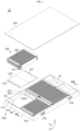
- FIG. 1 illustrates a battery pack 10 according to an embodiment of the present disclosure.
- the battery pack 10 includes a battery assembly 100 and a case 300 that accommodates one or more battery assemblies 100.
- the battery assembly 100 includes a plurality of cell units 200.
- Each cell unit 200 may include at least one battery cell and a cell cover that partially surrounds and covers the at least one battery cell, and may be stacked with other cell units in the width direction (Y-axis direction).
- These multiple cell units 200 may be stacked in one direction to be accommodated in the case 300.
- the case 300 has one or more accommodation rooms R1 having a bottom portion 310 on which the cell unit 200 is seated so that the accommodation room R1 accommodates the cell unit 200.
- the case 300 may be configured such that a plurality of battery assemblies 100 is respectively accommodated in separate accommodation rooms.
- the bottom portion 310 of the accommodation room R1 may include a pocket 310a configured to collect masses discharged and falling from the battery cell included in the cell unit 200.
- the heat sink 320 may have a guide hole 322 that is provided at a portion of the heat sink corresponding to the entrance of the pocket 310a so as to guide the masses to the entrance of the pocket 310a.
- This heat sink 320 may be made of a metal material with high thermal conductivity and heat resistance.
- the case 300 may have an accommodation space R2 for accommodating various electrical components required for the operation of the battery pack 10.
- the battery pack 10 may further include a control module.
- This control module may include a BMS (Battery Management System) that manages charging and discharging operations, SOC (State Of Charge), SOH (State Of Health), etc. of the battery cells included in the battery assembly, and may be mounted in the accommodation space R2 of the case 300.
- BMS Battery Management System
- SOC State Of Charge
- SOH State Of Health
- the support structure 110 may include a pair of side walls 112 and a pair of integrated end covers 114, respectively.
- the side walls 112 together with the integrated end cover 114 to be described later, bring the plurality of cell units 200 into close contact with each other to form a single cell unit block capable of being handled simultaneously.
- the side walls 112 may evenly distribute the pressure applied to the plurality of cell units 200 throughout the cell units 200.
- This side wall 112 may be made of a metal material including aluminum or stainless steel, or may be made of a material obtained from a combination of metal and polymer synthetic resin through insert molding.
- Each integrated end cover 114 may be disposed on one of both ends of the plurality of cell units 200 in the longitudinal direction (X-axis direction) of the plurality of cell units 200.
- the integrated end cover 114 may have one end connected to the first side wall and the other end connected to the second side wall so as to be configured to simultaneously cover openings of two or more cell covers among the cell covers of the plurality of cell units 200.
- the cell unit 200 may include a cell cover 210 that partially covers and supports at least one battery cell to remain in an upright state.
- the cell unit 200 may include at least one battery cell 202 and a cell cover 210.
- the battery cell 202 corresponds to the most basic secondary battery capable of being charged and discharged, and may be manufactured by storing an electrode assembly and electrolyte material inside a case and sealing the case.
- the electrode assembly may be manufactured by interposing a separator between the positive electrode and the negative electrode.
- This battery cell 202 may be configured as a pouch-type secondary battery cell having a predetermined length and height.
- electrode leads 202a electrically connected to the electrode assembly may be provided at both ends of the battery cell 202, respectively, in the longitudinal direction (X-axis direction) thereof.
- the cell cover 210 When the cell unit 200 is seated in the accommodation room R1 of the above-described case 300, the cell cover 210 may be disposed such that the entrance of the slot 214 faces the bottom portion 310 of the accommodation room R1. In this case, the entrance of the pocket 310a provided in the bottom portion 310 may be provided at a position corresponding to the entrance of the slot 214.
- the cell cover 210 may include a first cover portion 210a forming one side wall of the slot 214 into which at least one battery cell is inserted, a second cover portion 210b forming the other side wall of the slot 214, and a third cover portion 210c that connects the first cover portion 210a and the second cover portion 210b to form a distal end of the slot 214.
- the entrance of the slot 214 and the opening 216 through which the electrode lead of at least one battery cell 202 inserted into the slot 214 is exposed may be provided between the first cover portion 210a and the second cover portion 210b.
- the height L1 of the cell cover 210 (or the depth of the slot 214) may be configured to be greater than the height L2 of the battery cell 202 in the upright state. Accordingly, a free space produced inside the slot 214 into which the battery cell 202 is inserted may be used as a gas venting passage.
- the cell unit 200 may further include a bus bar assembly 220.
- the bus bar assembly 220 may include a bus bar 222 electrically connected to the electrode lead 202a of the battery cell 202 inserted into the cell cover 210 and a bus bar frame 224 disposed in the opening 216 of the cell cover 210 and supporting the bus bar 222.
- the cell cover 210 may further include a blocking portion 218 provided at the entrance of the slot 214 to block removal of the battery cell inserted into the slot 214.
- the blocking portion 218 may be configured to protrude from the ends of the first cover portion 210a and the second cover portion 210b toward the entrance of the slot 214, respectively, so as to support the lower ends of the battery cells inserted into the slot 214.
- the blocking portion 218 may have an insertion groove 218a into which a finger of a jig, which comes into contact with the inner surface of the cell cover 210 to change the width of the slot 214, that is, the gap between the first cover portion 210a and the second cover portion 210b, is inserted.
- This cell cover 210 may be formed integrally.
- the cell cover 210 may be manufactured integrally through a sheet metal processing process or an injection process.
- the cell cover 210 in a simplified structure described above may be made of a metal material with higher rigidity than the case of the battery cell, thereby protecting the battery cell covered by the cell cover from external impact or vibration.
- the cell cover 210 may be made of a material including stainless steel (SUS), which is easy to process and has high corrosion resistance.
- FIG. 6 illustrates a cross-sectional view taken along line A1-A1' of the battery pack shown in FIG. 1 .
- a gas passage leading to the pocket may be provided in the bottom portion of the battery pack case, thereby diversifying gas venting paths inside the battery pack and providing an alternative path in the case where other gas venting paths are blocked.
Landscapes
- Chemical & Material Sciences (AREA)
- Chemical Kinetics & Catalysis (AREA)
- Electrochemistry (AREA)
- General Chemical & Material Sciences (AREA)
- Engineering & Computer Science (AREA)
- Manufacturing & Machinery (AREA)
- Aviation & Aerospace Engineering (AREA)
- Battery Mounting, Suspending (AREA)
- Connection Of Batteries Or Terminals (AREA)
- Gas Exhaust Devices For Batteries (AREA)
- Secondary Cells (AREA)
Abstract
Description
- The present application claims priority to
Korean Patent Application No. 10-2022-0110386 filed on August 31, 2022 Korean Patent Application No. 10-2023-0065197 filed on May 19, 2023 - The present disclosure relates to a battery assembly, and a battery pack and a vehicle including the same, and more specifically, relates to a battery pack manufactured in a cell-to-pack manner and a vehicle including the same.
- In general, secondary batteries refer to batteries capable of being repeatedly charged and discharged, such as lithium-ion batteries, lithium polymer batteries, nickel-cadmium batteries, nickel-hydrogen batteries, nickel-zinc batteries, and the like. The output voltage of a battery cell, which is a basic unit of charging and discharging of the secondary batteries, is approximately 2.5V to 4.2V.
- Recently, secondary batteries have been applied to devices that require high output voltage and a large amount of charging capacity, such as electric vehicles or ESSs (Energy Storage Systems), and accordingly, a battery pack, which is manufactured in a manner of configuring a battery module by connecting a plurality of battery cells in series or parallel and reconnecting multiple battery modules configured above in series or parallel, has been widely used.
- However, as disclosed in
Korean Patent Publication No. 10-2379227 Korean Unexamined Patent Publication No. 10-2022-0052183 - In addition, in order to increase the energy density of the battery pack, if the existing cell-to-pack method of installing multiple battery cells directly in the pack case of the battery pack is applied to a pouch-type secondary battery with a soft case, it is difficult to handle or stack battery cells at the same time, and there is a risk of damage to the battery cells during the process of installing the battery cells in the pack case.
- In addition, according to the existing technologies, since particles or foreign substances discharged from the battery cell, in the case of thermal runaway of the battery cell, accumulate inside the battery pack, it is difficult to effectively vent gases, and the internal pressure of the battery pack increases, causing damage to the battery pack or explosion thereof.
- The present disclosure has been designed to solve the problems of the related art, and therefore the present disclosure is directed to providing a battery pack that reduces the overall weight and volume of the battery pack, increases the energy density, and enables safe and easy handling and installation of battery cells when manufacturing the battery pack, and a vehicle including the same.
- In addition, the present disclosure is directed to providing a battery pack that prevents structural damage or explosion of the battery pack when thermal runaway of the battery cell occurs and suppresses chain thermal runaway between battery cells, and a vehicle including the same.
- According to one aspect of the present disclosure, there is provided a battery pack including: a cell unit including at least one battery cell; and a case provided with an accommodation room having a bottom portion on which the cell unit is seated and accommodating the cell unit in the accommodation room, wherein the bottom portion comprises a pocket, the pocket may be configured to collect masses discharged and falling from the battery cell included in the cell unit.
- In an embodiment, the cell unit may further include a cell cover having a slot into which the at least one battery cell is inserted and an opening through which an electrode lead of the at least one battery cell inserted into the slot is exposed, and configured to cover the at least one battery cell inserted into the slot.
- In an embodiment, the cell cover may be disposed such that the entrance of the slot faces the bottom portion, and the entrance of the pocket may be provided at a position corresponding to the entrance of the slot.
- In an embodiment, the entrance of the pocket may be provided at a position corresponding to the entrance portion of the slot, which is adjacent to the electrode lead of the at least one battery cell, among the entrance of the slot.
- In an embodiment, the cell unit may further include: a bus bar electrically connected to the electrode lead; and a bus bar frame disposed in the opening of the cell cover to support the bus bar.
- In an embodiment, the bottom portion may further include a gas passage extending along the inside of the bottom portion, and the pocket may be configured to be connected to the gas passage.
- In an embodiment, the bottom portion may further include a membrane that blocks an inlet of the gas passage connected to the pocket, and the membrane may be configured to rupture when the surrounding pressure rises to a predetermined pressure or more to open the inlet of the gas passage.
- In an embodiment, the battery pack may further include a heat sink disposed between the cell unit and the bottom portion to cool the battery cell included in the cell unit, and the heat sink may have a guide hole provided in a portion of the heat sink corresponding to the entrance of the pocket to guide the masses to the entrance of the pocket.
- In an embodiment, the guide hole may be configured to gradually widen from the pocket to the cell unit.
- In an embodiment, the battery pack may further include a TIM (Thermal Interface Material) interposed between the cell unit and the heat sink.
- In an embodiment, the cell unit is provided in plural, and the plurality of cell units may be stacked on each other in one direction.
- In an embodiment, the at least one battery cell may be configured as a pouch-type secondary battery cell.
- A vehicle according to another aspect of the present disclosure may include the battery pack according to any one of the embodiment described above.
- According to the present disclosure, a pocket configured to collect a mass discharged from a battery cell and falling under its own weight may be provided in the bottom portion of a battery pack case, thereby effectively venting gases in the case of thermal runaway of the battery cell and preventing damage or explosion of the battery pack due to an increase in the internal pressure of the battery pack.
- In addition, since multiple battery cells may be partially covered by a cell cover with a simplified structure and directly mounted in the battery pack case, instead of being accommodated in a separate module case and mounted in the battery pack case, it is possible to reduce the weight and volume of the entire battery pack, increase the energy density of the battery pack, facilitate safe handling and installation of the battery cells when manufacturing the battery pack, and reduce manufacturing costs.
- In addition, a gas passage leading to the pocket may be provided in the bottom portion of the battery pack case, thereby diversifying gas venting paths inside the battery pack and providing an alternative path in the case where other gas venting paths are blocked.
- In addition, the gas flowing through a gas passage provided in the bottom portion of the battery pack case or another gas passage provided on the wall of the corresponding case may be vented in a predetermined direction through a gas valve, so that the gas venting direction of the battery pack mounted on the bottom of the vehicle may be set to the rear direction or lateral direction rather than the upward direction where the occupants are located, thereby improving the safety of the occupants.
- In addition, a blocking portion of the cell cover may support the battery cell inserted into a slot of the cell cover to block removal of the battery cell, thereby preventing the battery cell from changing in its position or leaving out of the cell cover and ensuring the safety and reliability of the battery pack.
- In addition, an insertion groove may be provided in the blocking portion of the cell cover such that a jig that comes into contact with the inner surface of the cell cover and changes the slot width of the cell cover is easily inserted thereto, thereby facilitating insertion of a battery cell into the cell cover and preventing damage to the battery cell.
- Furthermore, those skilled in the art to which the present disclosure pertains will be able to clearly understand from the following description that various embodiments according to the present disclosure are able to solve various technical problems not mentioned above.
-
-
FIG. 1 is a diagram illustrating a battery pack according to an embodiment of the present disclosure. -
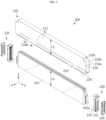
FIG. 2 is an exploded view illustrating a battery assembly of a battery pack according to an embodiment of the present disclosure. -
FIG. 3 is an enlarged view illustrating the area M1 inFIG. 1 . -
FIG. 4 is a diagram illustrating a cell unit of a battery pack according to an embodiment of the present disclosure. -
FIG. 5 is an exploded view illustrating the cell unit shown inFIG. 4 . -
FIG. 6 is a cross-sectional view taken along line A1-A1' of the battery pack shown inFIG. 1 . -
FIG. 7 is a diagram illustrating a lower portion of the cell unit shown inFIG. 6 . -
FIGS. 8 and9 are diagrams illustrating a method of assembling the cell unit shown inFIG. 4 . -
FIG. 10 is a diagram illustrating a cell cover according to a modified embodiment. -
FIG. 11 is a diagram illustrating a cell cover according to another modified embodiment. -
FIG. 12 is a diagram illustrating a vehicle according to an embodiment of the present disclosure. - Hereinafter, embodiments according to the present disclosure will be described in detail with reference to the accompanying drawings to clarify solutions corresponding to the technical problems of the present disclosure. However, in describing the present disclosure, a description of related known technology, which may obscure the gist of the present disclosure, may be omitted. In addition, the terms used in this specification are defined in consideration of the functions in the present disclosure and may vary depending on the intention of the designer, manufacturer, etc. or custom thereof. Therefore, definitions of the terms described below should be made based on the description throughout this specification.
- For reference, in this specification, terms indicating directions are based on the components shown in the attached drawings and are relative terms that may change depending on the postures or positions of the actual components.
-
FIG. 1 illustrates abattery pack 10 according to an embodiment of the present disclosure. - As shown in
FIG. 1 , thebattery pack 10 includes abattery assembly 100 and acase 300 that accommodates one ormore battery assemblies 100. - In addition, the
battery assembly 100 includes a plurality ofcell units 200. Eachcell unit 200 may include at least one battery cell and a cell cover that partially surrounds and covers the at least one battery cell, and may be stacked with other cell units in the width direction (Y-axis direction). - The battery cell included in each
cell unit 200 may be configured as a pouch-type secondary battery cell. In this case, the pouch-type secondary battery cell may be manufactured by storing the electrode assembly and electrolyte material in a pouch-type case and sealing the case. Depending on the embodiment, the battery cell may be configured in various forms, such as a prismatic secondary battery cell or a cylindrical secondary battery cell. - These
multiple cell units 200 may be stacked in one direction to be accommodated in thecase 300. - The
case 300 has one or more accommodation rooms R1 having abottom portion 310 on which thecell unit 200 is seated so that the accommodation room R1 accommodates thecell unit 200. For example, thecase 300 may be configured such that a plurality ofbattery assemblies 100 is respectively accommodated in separate accommodation rooms. - To this end, the
case 300 may include alower case 302 having an opening at the top thereof and an internal space leading to the opening, and anupper case 304 that covers the opening of thelower case 302. - The
lower case 302 may includewalls 312 that divide the interior space thereof into a plurality of accommodation rooms. Agas inlet 314 into which gas generated from thebattery assembly 100 accommodated in the accommodation room R1 flows may be provided on thewall 312 of thelower case 302 adjacent to each accommodation room R1. In addition, agas valve 316 for venting gas may be provided on the outer surface of thelower case 302. A gas passage connecting thegas inlet 314 and thegas valve 316 may be provided inside thelower case 302. - In this case, a gas venting path for venting gas to the
gas valve 316 may be provided individually for each accommodation room. That is, the gas generated from a first accommodation room may vent through a first gas venting path comprised of a first gas inlet, a first gas passage, and a first gas valve, and the gas generated from a second accommodation room may vent through a second gas venting path comprised of a second gas inlet, a second gas passage, and a second gas valve. - As will be described again below, the
bottom portion 310 of the accommodation room R1 may include apocket 310a configured to collect masses discharged and falling from the battery cell included in thecell unit 200. - In addition, the
battery pack 10 may further include aheat sink 320 that is disposed between thecell unit 200 of thebattery assembly 100 and thebottom portion 310 of the accommodation room R1 to cool the battery cells included in thecell unit 200. - In this case, the
heat sink 320 may have aguide hole 322 that is provided at a portion of the heat sink corresponding to the entrance of thepocket 310a so as to guide the masses to the entrance of thepocket 310a. Thisheat sink 320 may be made of a metal material with high thermal conductivity and heat resistance. - Depending on the embodiment, the
heat sink 320 may be configured integrally with thebottom portion 310 of the accommodation room R1. - Meanwhile, the
case 300 may have an accommodation space R2 for accommodating various electrical components required for the operation of thebattery pack 10. - In an embodiment, the
battery pack 10 may further include a control module. This control module may include a BMS (Battery Management System) that manages charging and discharging operations, SOC (State Of Charge), SOH (State Of Health), etc. of the battery cells included in the battery assembly, and may be mounted in the accommodation space R2 of thecase 300. - In addition, the
battery pack 10 may further include a switching unit. This switching unit may be configured to control the electrical connection between thebattery pack 10 and an external circuit. To this end, the switching unit may optionally include a current sensor, a power relay, a fuse, and the like. -
FIG. 2 is an exploded view illustrating thebattery assembly 100 of the battery pack shown inFIG. 1 . - As shown in
FIG. 2 , thebattery assembly 100 according to an embodiment of the present disclosure includes a plurality ofcell units 200 and asupport structure 110. - Each of the plurality of
cell units 200 includes at least one battery cell and is configured to be stacked side by side in the width direction (Y-axis direction). As will be described again below, eachcell unit 200 may include at least one battery cell that is a basic unit of charge and discharge and a cell cover that partially covers and supports the battery cell. - The
support structure 110 is configured to support the plurality ofcell units 200 and maintain the stacked state of the plurality ofcell units 200. To this end, thesupport structure 110 may include aside wall 112 and anintegrated end cover 114. Theside wall 112 and theintegrated end cover 114 may be disposed along the lateral perimeter of the plurality ofcell units 200 stacked on each other. - In an embodiment, the
support structure 110 may include a pair ofside walls 112 and a pair of integrated end covers 114, respectively. - In this case, the
side walls 112 may be configured such that each of them is disposed at both ends of the plurality ofcell units 200 in the width direction (Y-axis direction) or stacking direction of the plurality ofcell units 200, thereby supporting the plurality ofcell units 200. - That is, among the pair of side walls, a first side wall may be disposed adjacent to a first cell unit located at the outermost of one side of the plurality of
cell units 200, and a second side wall may be disposed adjacent to a second cell unit located at the outermost of the other side of the plurality ofcell units 200. - The
side walls 112, together with theintegrated end cover 114 to be described later, bring the plurality ofcell units 200 into close contact with each other to form a single cell unit block capable of being handled simultaneously. In this case, theside walls 112 may evenly distribute the pressure applied to the plurality ofcell units 200 throughout thecell units 200. - This
side wall 112 may be made of a metal material including aluminum or stainless steel, or may be made of a material obtained from a combination of metal and polymer synthetic resin through insert molding. - Each
integrated end cover 114 may be disposed on one of both ends of the plurality ofcell units 200 in the longitudinal direction (X-axis direction) of the plurality ofcell units 200. In addition, theintegrated end cover 114 may have one end connected to the first side wall and the other end connected to the second side wall so as to be configured to simultaneously cover openings of two or more cell covers among the cell covers of the plurality ofcell units 200. - To this end, the
side wall 112 may include aconnection portion 112a provided at both ends thereof and connected to one end or the other end of theintegrated end cover 114. According thereto, theintegrated end cover 114 may include a main body portion, which covers the openings of the plurality ofcell units 200, and acorresponding connection portion 114a extending from the main body portion and connected to theconnection portion 112a of theside wall 112. - In an embodiment, the
integrated end cover 114 may have avent hole 114b for venting gas generated from the battery cell of the cell unit, which is formed in each of portions of the integrated end cover corresponding to the openings of the plurality ofcell units 200. - In addition, as shown in
FIG. 2 , theintegrated end cover 114 may include asupport portion 114c that extends from the main body portion to the lower ends of the plurality ofcell units 200 and supports the lower ends of the plurality ofcell units 200. - This
integrated end cover 114 may be made of a metal material including aluminum or stainless steel or a polymer synthetic resin, or may be made of a material obtained from a combination of metal and polymer synthetic resin through insert molding. - As described above, since the
integrated end cover 114 may be applied to thebattery assembly 100 to support the cell units and integrally cover the openings of the cell units, unit end covers applied to each cell unit may be omitted, and the manufacturing process of the battery assembly may be simplified. -
FIG. 3 is an enlarged view illustrating the area M1 inFIG. 1 . - As shown in
FIG. 3 , theside wall 112 and theintegrated end cover 114 included in thesupport structure 110 of thebattery assembly 100 may be connected to each other, thereby supporting a plurality ofcell units 200. To this end, theconnection portion 112a of theside wall 112 may have an insertion groove into which thecorresponding connection portion 114a of theintegrated end cover 114 is inserted. - The
corresponding connection portion 114a of theintegrated end cover 114 may be inserted into the insertion groove provided in theconnection portion 112a of theside wall 112 and then fixed to theconnection portion 112a of theside wall 112 by a fastening member S1 such as a screw or bolt. - In addition, the
support portion 114c of theintegrated end cover 114 may be configured to extend from the main body portion of theintegrated end cover 114 to the lower ends of the plurality ofcell units 200 and support the lower ends of the plurality ofcell units 200. In this case, thesupport portion 114c of theintegrated end cover 114 may be configured to support a bus bar frame of eachcell unit 200. -
FIG. 4 illustrates acell unit 200 of a battery assembly according to an embodiment of the present disclosure. - As shown in
FIG. 4 , thecell unit 200 may include acell cover 210 that partially covers and supports at least one battery cell to remain in an upright state. - In addition, the
cell unit 200 may further include abus bar assembly 220. Thebus bar assembly 220 may include a bus bar that is electrically connected to an electrode lead of the battery cell inserted into thecell cover 210, and may be disposed at both ends of thecell cover 210 in the longitudinal direction (X-axis direction) thereof. -
FIG. 5 is an exploded view of thecell unit 200 shown inFIG. 4 . - As shown in
FIG. 5 , thecell unit 200 may include at least onebattery cell 202 and acell cover 210. - The
battery cell 202 corresponds to the most basic secondary battery capable of being charged and discharged, and may be manufactured by storing an electrode assembly and electrolyte material inside a case and sealing the case. The electrode assembly may be manufactured by interposing a separator between the positive electrode and the negative electrode. - This
battery cell 202 may be configured as a pouch-type secondary battery cell having a predetermined length and height. In addition, electrode leads 202a electrically connected to the electrode assembly may be provided at both ends of thebattery cell 202, respectively, in the longitudinal direction (X-axis direction) thereof. - The
cell cover 210 may be configured to partially cover and support at least onebattery cell 202 to remain in an upright state. For example, as shown inFIG. 5 , thecell cover 210 may be configured to partially cover and support the threebattery cells 202 stacked on each other, thereby maintaining the battery cells in an upright state. - To this end, the
cell cover 210 may be configured to have aslot 214 into which at least onebattery cell 202 is inserted and anopening 216 through which theelectrode lead 202a of at least onebattery cell 202 inserted into theslot 214 is exposed to the outside of thecell cover 210, and cover at least onebattery cell 202 inserted into theslot 214. - When the
cell unit 200 is seated in the accommodation room R1 of the above-describedcase 300, thecell cover 210 may be disposed such that the entrance of theslot 214 faces thebottom portion 310 of the accommodation room R1. In this case, the entrance of thepocket 310a provided in thebottom portion 310 may be provided at a position corresponding to the entrance of theslot 214. - This
cell cover 210 may be configured in an "n" shape or "u" shape so as to surround three sides of the at least one battery cell. - For example, the
cell cover 210 may include afirst cover portion 210a forming one side wall of theslot 214 into which at least one battery cell is inserted, asecond cover portion 210b forming the other side wall of theslot 214, and athird cover portion 210c that connects thefirst cover portion 210a and thesecond cover portion 210b to form a distal end of theslot 214. - That is, the
first cover portion 210a may cover one side of the battery cells inserted into theslot 214. In addition, thesecond cover portion 210b may cover the other side of the inserted battery cells. In addition, thethird cover portion 210c may cover the top of the inserted battery cells. - In this case, the entrance of the
slot 214 and theopening 216 through which the electrode lead of at least onebattery cell 202 inserted into theslot 214 is exposed may be provided between thefirst cover portion 210a and thesecond cover portion 210b. - The height L1 of the cell cover 210 (or the depth of the slot 214) may be configured to be greater than the height L2 of the
battery cell 202 in the upright state. Accordingly, a free space produced inside theslot 214 into which thebattery cell 202 is inserted may be used as a gas venting passage. - Although it is illustrated in
FIG. 5 that threebattery cells 202 are covered by onecell cover 210, the number of battery cells covered by thecell cover 210 may vary depending on the scale of thecell cover 210. - In an embodiment, the
cell unit 200 may further include abus bar assembly 220. Thebus bar assembly 220 may include abus bar 222 electrically connected to theelectrode lead 202a of thebattery cell 202 inserted into thecell cover 210 and abus bar frame 224 disposed in theopening 216 of thecell cover 210 and supporting thebus bar 222. - In addition, the
bus bar assembly 220 may further include an insulatingcover 226 that is disposed between thebus bar frame 224 and theintegrated end cover 114 of the above-describedsupport structure 110, and prevents short circuit of thebus bar 222. This insulatingcover 226 may be made of polymer synthetic resin with insulating properties. - In an embodiment, the
cell cover 210 may further include a blockingportion 218 provided at the entrance of theslot 214 to block removal of the battery cell inserted into theslot 214. The blockingportion 218 may be configured to protrude from the ends of thefirst cover portion 210a and thesecond cover portion 210b toward the entrance of theslot 214, respectively, so as to support the lower ends of the battery cells inserted into theslot 214. - In addition, in an embodiment, the blocking
portion 218 may have aninsertion groove 218a into which a finger of a jig, which comes into contact with the inner surface of thecell cover 210 to change the width of theslot 214, that is, the gap between thefirst cover portion 210a and thesecond cover portion 210b, is inserted. - This
cell cover 210 may be formed integrally. For example, thecell cover 210 may be manufactured integrally through a sheet metal processing process or an injection process. - The
cell cover 210 in a simplified structure described above may be made of a metal material with higher rigidity than the case of the battery cell, thereby protecting the battery cell covered by the cell cover from external impact or vibration. For example, thecell cover 210 may be made of a material including stainless steel (SUS), which is easy to process and has high corrosion resistance. - Although not shown in
FIGS. 4 and5 , thecell unit 200 may further include a clamping member configured to clamp thecell cover 210. In this case, the clamping member may be configured to clamp thecell cover 210 into which at least one battery cell is inserted so as to prevent theslot 214 of thecell cover 210 from opening or prevent thebattery cell 202 inserted into theslot 214 from being separated from thecell cover 210. This clamping member may be configured as a tape or a band-shaped metal material. -
FIG. 6 illustrates a cross-sectional view taken along line A1-A1' of the battery pack shown inFIG. 1 . - As shown in
FIG. 6 , when thecell unit 200 is seated in the accommodation room R1 of the above-describedcase 300, thecell cover 210 of thecell unit 200 may be disposed such that the entrance of itsslot 214 faces thebottom portion 310 of the accommodation room R1. - In addition, the entrance of the
pocket 310a provided in thebottom portion 310 may be provided at a position corresponding to the entrance of theslot 214. In this case, the entrance of thepocket 310a may be provided at a position corresponding to the entrance of theslot 214 of thecell cover 210, which is adjacent to theelectrode lead 202a of thebattery cell 202 inserted into theslot 214, among the entrance of the slot. This is due to the fact that when the thermal runaway of thebattery cell 202 occurs, gas frequently vents through the edge where theelectrode lead 202a of thebattery cell 202 is located. - Meanwhile, the
heat sink 320 disposed between thecell unit 200 and thebottom portion 310 may have aguide hole 322 that is provided at a portion of the heat sink corresponding to the entrance of thepocket 310a of thebottom portion 310 and guides the masses discharged from thebattery cell 202 to the entrance of thepocket 310a. To this end, theguide hole 322 may be configured to gradually widen from thepocket 310a to thecell unit 200. - In an embodiment, the
battery pack 10 may further include a TIM (Thermal Interface Material) 324 interposed between thecell unit 200 and theheat sink 320. By increasing the heat transfer rate between thecell unit 200 and theheat sink 320 through theTIM 324, the cooling performance of theheat sink 320 may be further improved. - In an embodiment, the
bottom portion 310 of thecase 300 may include agas passage 310b extending along the inside of thebottom portion 310. One end of thegas passage 310b may be connected to thepocket 310a, and the other end thereof may be connected to thegas valve 316 of thecase 300 described above. - In an embodiment, the
bottom portion 310 may further include amembrane 310c that blocks the inlet of thegas passage 310b connected to thepocket 310a. In this case, themembrane 310c may be configured to rupture when the surrounding pressure rises to a predetermined pressure and more, thereby opening the inlet of thegas passage 310b. To this end, notches or grooves in various shapes may be formed in themembrane 310c. -
FIG. 7 shows the lower portion of thecell unit 200 shown inFIG. 6 . - As shown in
FIG. 7 , the body of thebattery cell 202 inserted into thecell cover 210 of thecell unit 200 and thebus bar frame 224 coupled to the end of thecell cover 210 may be positioned at predetermined intervals, thereby providing a venting area VA through which the gas of thebattery cell 202 is vented at the lower end of thecell unit 200. The entrance to thepocket 310a described above may be provided at a position corresponding to the venting area VA. -
FIGS. 8 and9 illustrate a method of assembling thecell unit 200 shown inFIG. 4 . - First, as shown in
FIG. 8 , a finger of a jig may be inserted into thecell cover 210 to expand the gap between thefirst cover portion 210a and thesecond cover portion 210b of thecell cover 210, and then thebattery cell 202 may be safely inserted between thefirst cover portion 210a and thesecond cover portion 210b. - The blocking
portion 218 of thecell cover 210 may have an appropriate length and shape so as not to damage the battery cells inserted as described above. - Next, as shown in
FIG. 9 , after at least onebattery cell 202 is inserted into thecell cover 210, the finger of the jig is removed, so that thefirst cover portion 210a and thesecond cover portion 210b of thecell cover 210 return to their original positions by their own elastic force. - Then, the blocking
portion 218 of thecell cover 210 may support the lower end of thebattery cell 202 inserted between thefirst cover portion 210a and thesecond cover portion 210b to block removal of thebattery cell 202. To this end, the blockingportion 218 may be bent from the end of each of thefirst cover portion 210a and thesecond cover portion 210b toward the inside of thecell cover 210 to form a hook structure. -
FIG. 10 illustrates a battery cell cover 210' according to a modified embodiment. - As shown in
FIG. 10 , a blocking portion 218' of the battery cell cover 210' may be bent from the end of each of thefirst cover portion 210a and thesecond cover portion 210b of the battery cell cover 210' toward the inside of the battery cell cover 210', and then bent toward thethird cover portion 210c to form a hook structure. -
FIG. 11 illustrates abattery cell cover 210" according to another modified embodiment. - As shown in
FIG. 11 , a blockingportion 218" of thebattery cell cover 210" may be bent from the end of each of thefirst cover portion 210a and thesecond cover portion 210b of thebattery cell cover 210" toward thethird cover portion 210c and then bent again in a round shape toward the opposite side of thethird cover portion 210c. As described above, the blockingportion 218" may be configured to support battery cells by a round surface, thereby preventing damage to soft battery cells such as pouch-type battery cells. -
FIG. 12 illustrates avehicle 2 according to an embodiment of the present disclosure. - As shown in
FIG. 12 , thevehicle 2 according to an embodiment of the present disclosure may include at least onebattery pack 10 according to any one of the various embodiments described above. - The
battery pack 10 provided in thevehicle 2 as described above may provide electrical energy required for various operations of thevehicle 2. For reference, the battery pack according to the present disclosure may be applied to ESSs (Energy Storage Systems), as well as various electric devices or electric systems, in addition to vehicles. - As described above, according to the present disclosure, a pocket configured to collect a mass discharged from a battery cell and falling under its own weight may be provided in the bottom portion of a battery pack case, thereby effectively venting gases in the case of thermal runaway of the battery cell and preventing damage or explosion of the battery pack due to an increase in the internal pressure of the battery pack.
- In addition, since multiple battery cells may be partially covered by a cell cover with a simplified structure and directly mounted in the battery pack case, instead of being accommodated in a separate module case and mounted in the battery pack case, it is possible to reduce the weight and volume of the entire battery pack, increase the energy density of the battery pack, facilitate safe handling and installation of the battery cells when manufacturing the battery pack, and reduce manufacturing costs.
- In addition, a gas passage leading to the pocket may be provided in the bottom portion of the battery pack case, thereby diversifying gas venting paths inside the battery pack and providing an alternative path in the case where other gas venting paths are blocked.
- In addition, the gas flowing through a gas passage provided in the bottom portion of the battery pack case or another gas passage provided on the wall of the corresponding case may be vented in a predetermined direction through a gas valve, so that the gas venting direction of the battery pack mounted on the bottom of the vehicle may be set to the rear direction or lateral direction rather than the upward direction where the occupants are located, thereby improving the safety of the occupants.
- In addition, a blocking portion of the cell cover may support the battery cell inserted into a slot of the cell cover to block removal of the battery cell, thereby preventing the battery cell from changing in its position or leaving out of the cell cover and ensuring the safety and reliability of the battery pack.
- In addition, an insertion groove may be provided in the blocking portion of the cell cover such that a jig that comes into contact with the inner surface of the cell cover and changes the slot width of the cell cover is easily inserted thereto, thereby facilitating insertion of a battery cell into the cell cover and preventing damage to the battery cell.
- Furthermore, it goes without saying that the embodiments according to the present disclosure are able to solve various technical problems other than those mentioned in this specification in the relevant technical field as well as related technical fields.
- So far, the present disclosure has been described with reference to specific embodiments. However, those skilled in the art will clearly understand that various modified embodiments may be implemented within the technical scope of the present disclosure. Therefore, the previously disclosed embodiments should be considered as those intended to describe the present disclosure, instead of those intended to limit the present disclosure. In other words, the true scope of the technical idea of the present disclosure is shown in the claims, and all differences within the scope equivalent thereto should be construed as being included in the present disclosure.
Claims (13)
- A battery pack comprising:a cell unit comprising at least one battery cell; anda case provided with an accommodation room having a bottom portion on which the cell unit is seated and configured to accommodate the cell unit in the accommodation room,wherein the bottom portion comprises a pocket, the pocket is configured to collect masses discharged and falling from the battery cell included in the cell unit.
- The battery pack of claim 1, wherein the cell unit further comprises a cell cover having a slot into which the at least one battery cell is inserted and an opening through which an electrode lead of the at least one battery cell inserted into the slot is exposed, and configured to cover the at least one battery cell inserted into the slot.
- The battery pack of claim 2, wherein the cell cover is disposed such that the entrance of the slot faces the bottom portion, and
wherein the entrance of the pocket is provided at a position corresponding to the entrance of the slot. - The battery pack of claim 3, wherein the entrance of the pocket is provided at a position corresponding to the entrance of the slot, which is adjacent to the electrode lead of the at least one battery cell, among the entrance of the slot.
- The battery pack of claim 2, wherein the cell unit further comprises:a bus bar electrically connected to the electrode lead; anda bus bar frame disposed in the opening of the cell cover to support the bus bar.
- The battery pack of claim 1, wherein the bottom portion further comprises a gas passage extending along the inside of the bottom portion, and
wherein the pocket is configured to be connected to the gas passage. - The battery pack of claim 6, wherein the bottom portion further comprises a membrane configured to block an inlet of the gas passage connected to the pocket, and
wherein the membrane is configured to rupture when the surrounding pressure rises to a predetermined pressure or more to open the inlet of the gas passage. - The battery pack of claim 1, further comprising a heat sink disposed between the cell unit and the bottom portion and configured to cool the battery cell included in the cell unit,
wherein the heat sink has a guide hole provided in a portion of the heat sink corresponding to the entrance of the pocket to guide the masses to the entrance of the pocket. - The battery pack of claim 8, wherein the guide hole is configured to gradually widen from the pocket to the cell unit.
- The battery pack of claim 8, further comprising a TIM (Thermal Interface Material) interposed between the cell unit and the heat sink.
- The battery pack of claim 1, wherein the cell unit is provided in plural,
wherein the plurality of cell units is stacked on each other in one direction. - The battery pack of claim 1, wherein the at least one battery cell is configured as a pouch-type secondary battery cell.
- A vehicle comprising the battery pack according to any one of claims 1 to 12.
Applications Claiming Priority (3)
| Application Number | Priority Date | Filing Date | Title |
|---|---|---|---|
| KR20220110386 | 2022-08-31 | ||
| KR1020230065197A KR20240030986A (en) | 2022-08-31 | 2023-05-19 | Battery pack and vehicle including same |
| PCT/KR2023/011533 WO2024049036A1 (en) | 2022-08-31 | 2023-08-04 | Battery pack and vehicle including same |
Publications (2)
| Publication Number | Publication Date |
|---|---|
| EP4395040A1 true EP4395040A1 (en) | 2024-07-03 |
| EP4395040A4 EP4395040A4 (en) | 2025-04-30 |
Family
ID=90098175
Family Applications (1)
| Application Number | Title | Priority Date | Filing Date |
|---|---|---|---|
| EP23860716.2A Pending EP4395040A4 (en) | 2022-08-31 | 2023-08-04 | BATTERY PACK AND VEHICLE WITH IT |
Country Status (4)
| Country | Link |
|---|---|
| US (1) | US20250167387A1 (en) |
| EP (1) | EP4395040A4 (en) |
| JP (1) | JP7815443B2 (en) |
| WO (1) | WO2024049036A1 (en) |
Cited By (2)
| Publication number | Priority date | Publication date | Assignee | Title |
|---|---|---|---|---|
| EP4567995A4 (en) * | 2022-08-31 | 2026-01-21 | Lg Energy Solution Ltd | BATTERY PACK AND VEHICLE WITH IT |
| EP4723298A1 (en) * | 2024-10-02 | 2026-04-08 | Samsung Sdi Co., Ltd. | Battery module and battery pack including the battery module |
Family Cites Families (23)
| Publication number | Priority date | Publication date | Assignee | Title |
|---|---|---|---|---|
| JP3914707B2 (en) * | 2000-06-19 | 2007-05-16 | 本田技研工業株式会社 | Storage element and holding structure thereof |
| JP5331517B2 (en) * | 2008-04-14 | 2013-10-30 | 日産自動車株式会社 | Assembled battery and vehicle equipped with the assembled battery |
| JP6144658B2 (en) * | 2014-10-01 | 2017-06-07 | トヨタ自動車株式会社 | In-vehicle power supply |
| JP6344293B2 (en) * | 2015-04-03 | 2018-06-20 | 株式会社デンソー | Battery pack |
| KR20170069003A (en) * | 2015-12-10 | 2017-06-20 | 삼성에스디아이 주식회사 | Battery Module |
| JP6601235B2 (en) * | 2016-01-26 | 2019-11-06 | 株式会社デンソー | Battery pack |
| JP7010671B2 (en) * | 2017-11-15 | 2022-01-26 | スカッドエレクトロニクスジャパン株式会社 | Lithium ion battery module |
| US11024901B2 (en) * | 2018-01-19 | 2021-06-01 | Hanon Systems | Battery cooling plate with integrated air vents |
| KR102330378B1 (en) * | 2018-04-20 | 2021-11-22 | 주식회사 엘지에너지솔루션 | Battery Pack with degassing flow path |
| KR102379227B1 (en) | 2018-12-26 | 2022-03-24 | 주식회사 엘지에너지솔루션 | Battery module, battery pack comprising the battery module and vehicle comprising the battery pack |
| KR20210019830A (en) | 2019-08-13 | 2021-02-23 | 주식회사 라이프단열 | Roof structure and construction method thereof |
| CN111162241B (en) | 2020-01-19 | 2025-05-23 | 武汉理工大学 | Battery electrolyte drainage structure |
| US20210359374A1 (en) | 2020-05-12 | 2021-11-18 | Samsung Sdi Co., Ltd. | Battery system and vehicle including the battery system |
| EP3965211B1 (en) * | 2020-07-10 | 2023-11-29 | Contemporary Amperex Technology Co., Limited | Box body for battery, battery, electric device, and method and device for preparing battery |
| KR102924941B1 (en) * | 2020-08-13 | 2026-02-09 | 에스케이온 주식회사 | Battery module |
| KR20220052183A (en) | 2020-10-20 | 2022-04-27 | 현대자동차주식회사 | Battery module and battery pack comprising the same |
| ES3057109T3 (en) | 2021-01-11 | 2026-02-26 | Lg Energy Solution Ltd | Battery pack and vehicle including same |
| KR102530748B1 (en) | 2021-01-29 | 2023-05-11 | 주식회사 지앤시바이오 | Apparatus and method for detecting sample using nanowire fet |
| KR102941327B1 (en) | 2021-02-19 | 2026-03-20 | 에스케이온 주식회사 | battery pack |
| CN114374049A (en) | 2022-02-10 | 2022-04-19 | 中创新航科技股份有限公司 | Battery box and battery package |
| CN217062334U (en) | 2022-02-23 | 2022-07-26 | 蜂巢能源科技股份有限公司 | battery pack |
| CN217334327U (en) | 2022-05-16 | 2022-08-30 | 小米汽车科技有限公司 | Battery pack and vehicle |
| EP4350861A4 (en) * | 2022-06-10 | 2025-03-12 | LG Energy Solution, Ltd. | Battery pack, method for manufacturing battery pack, and vehicle including battery pack |
-
2023
- 2023-08-04 JP JP2024534757A patent/JP7815443B2/en active Active
- 2023-08-04 US US18/835,100 patent/US20250167387A1/en active Pending
- 2023-08-04 WO PCT/KR2023/011533 patent/WO2024049036A1/en not_active Ceased
- 2023-08-04 EP EP23860716.2A patent/EP4395040A4/en active Pending
Cited By (2)
| Publication number | Priority date | Publication date | Assignee | Title |
|---|---|---|---|---|
| EP4567995A4 (en) * | 2022-08-31 | 2026-01-21 | Lg Energy Solution Ltd | BATTERY PACK AND VEHICLE WITH IT |
| EP4723298A1 (en) * | 2024-10-02 | 2026-04-08 | Samsung Sdi Co., Ltd. | Battery module and battery pack including the battery module |
Also Published As
| Publication number | Publication date |
|---|---|
| JP2025500825A (en) | 2025-01-15 |
| WO2024049036A1 (en) | 2024-03-07 |
| US20250167387A1 (en) | 2025-05-22 |
| EP4395040A4 (en) | 2025-04-30 |
| JP7815443B2 (en) | 2026-02-17 |
Similar Documents
| Publication | Publication Date | Title |
|---|---|---|
| EP4050718B1 (en) | Battery pack having improved fixing structure and gas discharge structure, and electronic device and vehicle including same | |
| US12586865B2 (en) | Battery module, and battery pack and vehicle comprising the same | |
| CN107431163B (en) | Battery pack and method of making the same | |
| KR102874380B1 (en) | Battery module and battery pack including the same and vehicle including the same | |
| US20250364680A1 (en) | Battery pack and battery pack manufacturing method, and vehicle including battery pack | |
| EP4395040A1 (en) | Battery pack and vehicle including same | |
| EP4471960A1 (en) | Battery module, and battery pack and vehicle comprising same | |
| KR20240012302A (en) | Battery pack and device including the same | |
| US20250183471A1 (en) | Battery Pack and Vehicle Including the Same | |
| KR20240012285A (en) | Battery assembly and battery pack and vehicle including same | |
| KR20240086512A (en) | Battery cell, and battery pack and vehicle including same | |
| KR102926474B1 (en) | Battery pack and vehicle including same | |
| EP3989334A1 (en) | Battery module, and battery pack and vehicle comprising same | |
| EP4418434B1 (en) | Battery module, and battery pack and vehicle including same | |
| EP4567995A1 (en) | Battery pack and vehicle including same | |
| KR20240030986A (en) | Battery pack and vehicle including same | |
| EP4404363A1 (en) | Battery cell, and battery pack and vehicle including same | |
| CN118077092A (en) | Battery pack and vehicle including the battery pack | |
| EP4383428A1 (en) | Battery assembly, and battery pack and vehicle which comprise same | |
| EP4391188B1 (en) | Battery pack and vehicle including the same | |
| EP4557466A1 (en) | Battery pack and device including same | |
| EP4425662A1 (en) | Battery pack and device comprising same | |
| KR20240031064A (en) | Battery pack and vehicle including same | |
| KR20240012293A (en) | Battery pack and device including same | |
| CN117941149A (en) | Battery pack and vehicle including the same |
Legal Events
| Date | Code | Title | Description |
|---|---|---|---|
| STAA | Information on the status of an ep patent application or granted ep patent |
Free format text: STATUS: THE INTERNATIONAL PUBLICATION HAS BEEN MADE |
|
| PUAI | Public reference made under article 153(3) epc to a published international application that has entered the european phase |
Free format text: ORIGINAL CODE: 0009012 |
|
| STAA | Information on the status of an ep patent application or granted ep patent |
Free format text: STATUS: REQUEST FOR EXAMINATION WAS MADE |
|
| 17P | Request for examination filed |
Effective date: 20240327 |
|
| AK | Designated contracting states |
Kind code of ref document: A1 Designated state(s): AL AT BE BG CH CY CZ DE DK EE ES FI FR GB GR HR HU IE IS IT LI LT LU LV MC ME MK MT NL NO PL PT RO RS SE SI SK SM TR |
|
| A4 | Supplementary search report drawn up and despatched |
Effective date: 20250331 |
|
| RIC1 | Information provided on ipc code assigned before grant |
Ipc: H01M 50/249 20210101ALI20250325BHEP Ipc: H01M 10/653 20140101ALI20250325BHEP Ipc: H01M 10/6551 20140101ALI20250325BHEP Ipc: H01M 50/502 20210101ALI20250325BHEP Ipc: H01M 50/342 20210101ALI20250325BHEP Ipc: H01M 50/211 20210101ALI20250325BHEP Ipc: H01M 50/105 20210101ALI20250325BHEP Ipc: H01M 50/367 20210101ALI20250325BHEP Ipc: H01M 50/383 20210101AFI20250325BHEP |
|
| STAA | Information on the status of an ep patent application or granted ep patent |
Free format text: STATUS: EXAMINATION IS IN PROGRESS |
|
| DAV | Request for validation of the european patent (deleted) | ||
| DAX | Request for extension of the european patent (deleted) | ||
| 17Q | First examination report despatched |
Effective date: 20251118 |