EP4395020A2 - Batterie - Google Patents
Batterie Download PDFInfo
- Publication number
- EP4395020A2 EP4395020A2 EP23175539.8A EP23175539A EP4395020A2 EP 4395020 A2 EP4395020 A2 EP 4395020A2 EP 23175539 A EP23175539 A EP 23175539A EP 4395020 A2 EP4395020 A2 EP 4395020A2
- Authority
- EP
- European Patent Office
- Prior art keywords
- terminal post
- battery
- hole
- sealing member
- endpoint
- Prior art date
- Legal status (The legal status is an assumption and is not a legal conclusion. Google has not performed a legal analysis and makes no representation as to the accuracy of the status listed.)
- Withdrawn
Links
Images
Classifications
-
- H—ELECTRICITY
- H01—ELECTRIC ELEMENTS
- H01M—PROCESSES OR MEANS, e.g. BATTERIES, FOR THE DIRECT CONVERSION OF CHEMICAL ENERGY INTO ELECTRICAL ENERGY
- H01M50/00—Constructional details or processes of manufacture of the non-active parts of electrochemical cells other than fuel cells, e.g. hybrid cells
- H01M50/10—Primary casings; Jackets or wrappings
- H01M50/102—Primary casings; Jackets or wrappings characterised by their shape or physical structure
- H01M50/107—Primary casings; Jackets or wrappings characterised by their shape or physical structure having curved cross-section, e.g. round or elliptic
-
- H—ELECTRICITY
- H01—ELECTRIC ELEMENTS
- H01M—PROCESSES OR MEANS, e.g. BATTERIES, FOR THE DIRECT CONVERSION OF CHEMICAL ENERGY INTO ELECTRICAL ENERGY
- H01M50/00—Constructional details or processes of manufacture of the non-active parts of electrochemical cells other than fuel cells, e.g. hybrid cells
- H01M50/10—Primary casings; Jackets or wrappings
- H01M50/116—Primary casings; Jackets or wrappings characterised by the material
- H01M50/117—Inorganic material
- H01M50/119—Metals
-
- H—ELECTRICITY
- H01—ELECTRIC ELEMENTS
- H01M—PROCESSES OR MEANS, e.g. BATTERIES, FOR THE DIRECT CONVERSION OF CHEMICAL ENERGY INTO ELECTRICAL ENERGY
- H01M50/00—Constructional details or processes of manufacture of the non-active parts of electrochemical cells other than fuel cells, e.g. hybrid cells
- H01M50/10—Primary casings; Jackets or wrappings
- H01M50/172—Arrangements of electric connectors penetrating the casing
- H01M50/174—Arrangements of electric connectors penetrating the casing adapted for the shape of the cells
- H01M50/179—Arrangements of electric connectors penetrating the casing adapted for the shape of the cells for cells having curved cross-section, e.g. round or elliptic
-
- H—ELECTRICITY
- H01—ELECTRIC ELEMENTS
- H01M—PROCESSES OR MEANS, e.g. BATTERIES, FOR THE DIRECT CONVERSION OF CHEMICAL ENERGY INTO ELECTRICAL ENERGY
- H01M50/00—Constructional details or processes of manufacture of the non-active parts of electrochemical cells other than fuel cells, e.g. hybrid cells
- H01M50/10—Primary casings; Jackets or wrappings
- H01M50/183—Sealing members
- H01M50/19—Sealing members characterised by the material
- H01M50/191—Inorganic material
-
- H—ELECTRICITY
- H01—ELECTRIC ELEMENTS
- H01M—PROCESSES OR MEANS, e.g. BATTERIES, FOR THE DIRECT CONVERSION OF CHEMICAL ENERGY INTO ELECTRICAL ENERGY
- H01M50/00—Constructional details or processes of manufacture of the non-active parts of electrochemical cells other than fuel cells, e.g. hybrid cells
- H01M50/50—Current conducting connections for cells or batteries
- H01M50/543—Terminals
- H01M50/552—Terminals characterised by their shape
- H01M50/559—Terminals adapted for cells having curved cross-section, e.g. round, elliptic or button cells
-
- Y—GENERAL TAGGING OF NEW TECHNOLOGICAL DEVELOPMENTS; GENERAL TAGGING OF CROSS-SECTIONAL TECHNOLOGIES SPANNING OVER SEVERAL SECTIONS OF THE IPC; TECHNICAL SUBJECTS COVERED BY FORMER USPC CROSS-REFERENCE ART COLLECTIONS [XRACs] AND DIGESTS
- Y02—TECHNOLOGIES OR APPLICATIONS FOR MITIGATION OR ADAPTATION AGAINST CLIMATE CHANGE
- Y02E—REDUCTION OF GREENHOUSE GAS [GHG] EMISSIONS, RELATED TO ENERGY GENERATION, TRANSMISSION OR DISTRIBUTION
- Y02E60/00—Enabling technologies; Technologies with a potential or indirect contribution to GHG emissions mitigation
- Y02E60/10—Energy storage using batteries
Definitions
- a rubber member may be used to seal between a terminal post and a battery case of a battery.
- the rubber member is prone to failure.
- the disclosure provides a battery to improve the service performance of the battery.
- the disclosure provides a battery, including:
- connection In particular, a reference to “the” object or “a” and “an” object is intended to denote also one of a possible plurality of such objects.
- the terms “connect”, “fix” should be broadly interpreted, for example, the term “connect” can be “fixedly connect”, “detachably connect”, “integrally connect”, “electrically connect” or “signal connect”.
- the term “connect” also can be “directly connect” or “indirectly connect via a medium”.
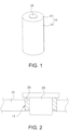
- the battery includes: a battery case 10, where a terminal post through hole 11 is arranged on the battery case 10; a terminal post 20, where the terminal post 20 is arranged in the terminal post through hole 11; and a rigid sealing member 30, where a glass transition temperature of the rigid sealing member 30 is 300°C to 600°C, and the rigid sealing member 30 is at least partially arranged in the terminal post through hole 11 to seal the terminal post 20 and the battery case 10.
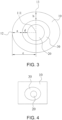
- a circumferential outer edge of a surface of the battery case 10 provided with the terminal post through hole 11 has a first endpoint 12 and a second endpoint 13.
- a center point 111 of the terminal post through hole 11 forms a first connecting line and a second connecting line respectively with the first endpoint 12 and the second endpoint 13.
- the first connecting line is substantially perpendicular to the second connecting line.
- a distance between the first endpoint 12 and a hole wall of the terminal post through hole 11 along an extending direction of the first connecting line is defined as a
- a distance between the second endpoint 13 and the hole wall of the terminal post through hole 11 along an extending direction of the second connecting line is defined as b
- 0.9 ⁇ a/b ⁇ 1.1 0.9 ⁇ a/b ⁇ 1.1.
- a battery of one embodiment of the disclosure includes a battery case 10, a terminal post 20, and a rigid sealing member 30.
- the terminal post 20 is arranged in a terminal post through hole 11 on the battery case 10, and the rigid sealing member 30 is at least partially arranged in the terminal post through hole 11. In this way, the terminal post 20 and the battery case 10 can be effectively sealed. Since the rigid sealing member 30 has a high hardness, problems such as compression deformation failure can be avoided, so that the sealing performance of the rigid sealing member 30 between the terminal post 20 and the battery case 10 can be improved.
- a circumferential outer edge of a surface of the battery case 10 provided with the terminal post through hole 11 has a first endpoint 12 and a second endpoint 13.
- a center point 111 of the terminal post through hole 11 forms a first connecting line and a second connecting line respectively with the first endpoint 12 and the second endpoint 13.
- the first connecting line is substantially perpendicular to the second connecting line.
- a distance between the first endpoint 12 and a hole wall of the terminal post through hole 11 along an extending direction of the first connecting line is defined as a
- a distance between the second endpoint 13 and the hole wall of the terminal post through hole 11 along an extending direction of the second connecting line is defined as b
- 0.9 ⁇ a/b ⁇ 1.1 0.9 ⁇ a/b ⁇ 1.1.
- the distances between the first endpoint 12 and the second endpoint 13 and the rigid sealing member 30 are relatively uniform, to ensure that the battery case 10 can provide relatively balanced compression force to the rigid sealing member 30, thereby avoiding the risk of failure of the rigid sealing member 30 and improving the safety performance of the battery set.
- the rigid sealing member 30 has a high hardness, the rigid sealing member 30 is not prone to problems such as aging. Correspondingly, the mechanical impact resistance of the rigid sealing member 30 may be relatively low. Therefore, it is necessary to avoid the problem of excessive and uneven stress on the rigid sealing member 30.
- the first endpoint 12 and the second endpoint 13 of the battery case 10 that apply an external force to the rigid sealing member 30 are arranged to be at approximately the same distance from the rigid sealing member 30, so that the problem of excessive and uneven stress on the rigid sealing member 30 can be avoided, thereby preventing the rigid sealing member 30 from cracking under a mechanical impact force to affect the sealing performance of the rigid sealing member 30.
- a glass transition temperature of the rigid sealing member 30 is 300°C to 600°C, that is, the temperature at which the rigid sealing member 30 starts to soften is 300°C to 600°C, which is a relatively high temperature. Therefore, the rigid sealing member 30 is not prone to softening, thereby avoiding the problem of sealing failure during the use of the battery.
- the circumferential outer edge of the surface of the battery case 10 provided with the terminal post through hole 11 has the first endpoint 12 and the second endpoint 13.
- the center point 111 of the terminal post through hole 11 forms the first connecting line and the second connecting line respectively with the first endpoint 12 and the second endpoint 13.
- the first connecting line is substantially perpendicular to the second connecting line.
- the first connecting line and the second connecting line are denoted by two dashed lines in FIG. 3 .
- the distance between the first endpoint 12 and the hole wall of the terminal post through hole 11 along the extending direction of the first connecting line is defined as a
- the distance between the second endpoint 13 and the hole wall of the terminal post through hole 11 along the extending direction of the second connecting line is defined as b
- 0.9 ⁇ a/b ⁇ 1.1 the first endpoint 12 and the second endpoint 13 are at approximately the same distance from the rigid sealing member 30, so the forces applied by the first endpoint 12 and the second endpoint 13 on the rigid sealing member 30 are approximately the same, thereby avoiding problems such as cracking of the rigid sealing member 30 under the forces.
- the battery may further include a cell.
- the cell is arranged in the battery case 10.
- the cell may be electrically connected to the battery case 10, or the cell may be connected to the terminal post 20 on the battery case 10.
- the battery may be a wound battery, that is, the first electrode plate, the second electrode plate of a polarity opposite to that of the first electrode plate, and the separator arranged between the first electrode plate and the second electrode plate are wound to obtain a wound cell.
- the battery may be a cylindrical battery.
- the battery may be a wound battery, that is, the first electrode plate, the second electrode plate of a polarity opposite to that of the first electrode plate, and the separator arranged between the first electrode plate and the second electrode plate are wound to obtain a wound cell.
- the rigid sealing member 30 includes glass, ceramic, or glass-ceramic, to avoid aging of the rigid sealing member 30.
- problems such as damage to the rigid sealing member 30 can be avoided by controlling the uniformity of forces applied by the battery case 10 to the terminal post 20, thereby ensuring the sealing performance of the rigid sealing member 30.
- the battery case 10 may be made of steel, aluminum, copper, or a combination thereof, which is not limited herein.
- the rigid sealing member 30 is hot-melted in the terminal post through hole 11, to ensure that the rigid sealing member 30 reliably seals the terminal post 20 and the battery case 10, and improve the efficiency of fabrication and installation of the rigid sealing member 30, thereby improving the installation efficiency of the battery.
- one part of the rigid sealing member 30 may be located inside the terminal post through hole 11, and the other part of the rigid sealing member 30 may be located outside the terminal post through hole 11, so that the sealing performance of the rigid sealing member 30 can be improved.
- One embodiment of the disclosure further provides a battery set, including the battery described above.
Landscapes
- Chemical & Material Sciences (AREA)
- Chemical Kinetics & Catalysis (AREA)
- Electrochemistry (AREA)
- General Chemical & Material Sciences (AREA)
- Inorganic Chemistry (AREA)
- Sealing Battery Cases Or Jackets (AREA)
- Connection Of Batteries Or Terminals (AREA)
Applications Claiming Priority (1)
| Application Number | Priority Date | Filing Date | Title |
|---|---|---|---|
| CN202211733909.9A CN115966821A (zh) | 2022-12-30 | 2022-12-30 | 电池 |
Publications (2)
| Publication Number | Publication Date |
|---|---|
| EP4395020A2 true EP4395020A2 (de) | 2024-07-03 |
| EP4395020A3 EP4395020A3 (de) | 2024-07-10 |
Family
ID=85889490
Family Applications (1)
| Application Number | Title | Priority Date | Filing Date |
|---|---|---|---|
| EP23175539.8A Withdrawn EP4395020A3 (de) | 2022-12-30 | 2023-05-26 | Batterie |
Country Status (2)
| Country | Link |
|---|---|
| EP (1) | EP4395020A3 (de) |
| CN (1) | CN115966821A (de) |
Family Cites Families (4)
| Publication number | Priority date | Publication date | Assignee | Title |
|---|---|---|---|---|
| US20080085451A1 (en) * | 2006-10-06 | 2008-04-10 | Greatbatch Ltd. | Highly Compact Electrochemical Cell |
| DE102013006463B4 (de) * | 2013-04-15 | 2017-01-19 | Schott Ag | Durchführung |
| CN217589378U (zh) * | 2022-06-28 | 2022-10-14 | 中创新航科技股份有限公司 | 电池 |
| CN219086103U (zh) * | 2022-12-30 | 2023-05-26 | 中创新航科技股份有限公司 | 电池 |
-
2022
- 2022-12-30 CN CN202211733909.9A patent/CN115966821A/zh active Pending
-
2023
- 2023-05-26 EP EP23175539.8A patent/EP4395020A3/de not_active Withdrawn
Also Published As
| Publication number | Publication date |
|---|---|
| EP4395020A3 (de) | 2024-07-10 |
| CN115966821A (zh) | 2023-04-14 |
Similar Documents
| Publication | Publication Date | Title |
|---|---|---|
| KR101066257B1 (ko) | 원통형 이차전지 | |
| EP2733778B1 (de) | Jelly-roll mit verbesserter verarbeitbarkeit und batteriezelle damit | |
| KR102361705B1 (ko) | 커버를 갖는 이차 전지 | |
| EP4343931A1 (de) | Batterie | |
| CN114497904A (zh) | 电池的装配方法及电池 | |
| CN114678594A (zh) | 电池 | |
| CN114614208A (zh) | 电池 | |
| WO2019103393A1 (ko) | 최외곽 전극의 구조 및 집전체의 재질에 의해 사용 안전성이 향상된 전극 조립체 및 상기 전극 조립체를 갖는 리튬이온 이차전지 | |
| CN114614209A (zh) | 电池 | |
| EP4386950A1 (de) | Batteriepack | |
| CN218448353U (zh) | 单体电池 | |
| EP4395020A2 (de) | Batterie | |
| CN216720097U (zh) | 电池盖板组件、电池及电池组 | |
| CN217086806U (zh) | 电池及电池组 | |
| CN219086103U (zh) | 电池 | |
| CN114725477A (zh) | 电芯单元、电池及电池的装配方法 | |
| JP2011077019A (ja) | 二次電池 | |
| CN219476835U (zh) | 电池及电池组 | |
| CN218448331U (zh) | 电池 | |
| CN217823030U (zh) | 电池盖板组件及电池 | |
| CN218731628U (zh) | 电池 | |
| CN218448366U (zh) | 单体电池 | |
| CN218957858U (zh) | 电池 | |
| CN216980648U (zh) | 电芯单元及电池 | |
| CN218101465U (zh) | 电池 |
Legal Events
| Date | Code | Title | Description |
|---|---|---|---|
| PUAI | Public reference made under article 153(3) epc to a published international application that has entered the european phase |
Free format text: ORIGINAL CODE: 0009012 |
|
| STAA | Information on the status of an ep patent application or granted ep patent |
Free format text: STATUS: REQUEST FOR EXAMINATION WAS MADE |
|
| PUAL | Search report despatched |
Free format text: ORIGINAL CODE: 0009013 |
|
| 17P | Request for examination filed |
Effective date: 20230526 |
|
| AK | Designated contracting states |
Kind code of ref document: A2 Designated state(s): AL AT BE BG CH CY CZ DE DK EE ES FI FR GB GR HR HU IE IS IT LI LT LU LV MC ME MK MT NL NO PL PT RO RS SE SI SK SM TR |
|
| AK | Designated contracting states |
Kind code of ref document: A3 Designated state(s): AL AT BE BG CH CY CZ DE DK EE ES FI FR GB GR HR HU IE IS IT LI LT LU LV MC ME MK MT NL NO PL PT RO RS SE SI SK SM TR |
|
| RIC1 | Information provided on ipc code assigned before grant |
Ipc: H01M 50/559 20210101ALI20240604BHEP Ipc: H01M 50/191 20210101ALI20240604BHEP Ipc: H01M 50/179 20210101ALI20240604BHEP Ipc: H01M 50/119 20210101ALI20240604BHEP Ipc: H01M 50/107 20210101AFI20240604BHEP |
|
| STAA | Information on the status of an ep patent application or granted ep patent |
Free format text: STATUS: THE APPLICATION IS DEEMED TO BE WITHDRAWN |
|
| 18D | Application deemed to be withdrawn |
Effective date: 20250111 |