EP4395020A2 - Battery - Google Patents
Battery Download PDFInfo
- Publication number
- EP4395020A2 EP4395020A2 EP23175539.8A EP23175539A EP4395020A2 EP 4395020 A2 EP4395020 A2 EP 4395020A2 EP 23175539 A EP23175539 A EP 23175539A EP 4395020 A2 EP4395020 A2 EP 4395020A2
- Authority
- EP
- European Patent Office
- Prior art keywords
- terminal post
- battery
- hole
- sealing member
- endpoint
- Prior art date
- Legal status (The legal status is an assumption and is not a legal conclusion. Google has not performed a legal analysis and makes no representation as to the accuracy of the status listed.)
- Withdrawn
Links
Images
Classifications
-
- H—ELECTRICITY
- H01—ELECTRIC ELEMENTS
- H01M—PROCESSES OR MEANS, e.g. BATTERIES, FOR THE DIRECT CONVERSION OF CHEMICAL ENERGY INTO ELECTRICAL ENERGY
- H01M50/00—Constructional details or processes of manufacture of the non-active parts of electrochemical cells other than fuel cells, e.g. hybrid cells
- H01M50/10—Primary casings; Jackets or wrappings
- H01M50/102—Primary casings; Jackets or wrappings characterised by their shape or physical structure
- H01M50/107—Primary casings; Jackets or wrappings characterised by their shape or physical structure having curved cross-section, e.g. round or elliptic
-
- H—ELECTRICITY
- H01—ELECTRIC ELEMENTS
- H01M—PROCESSES OR MEANS, e.g. BATTERIES, FOR THE DIRECT CONVERSION OF CHEMICAL ENERGY INTO ELECTRICAL ENERGY
- H01M50/00—Constructional details or processes of manufacture of the non-active parts of electrochemical cells other than fuel cells, e.g. hybrid cells
- H01M50/10—Primary casings; Jackets or wrappings
- H01M50/116—Primary casings; Jackets or wrappings characterised by the material
- H01M50/117—Inorganic material
- H01M50/119—Metals
-
- H—ELECTRICITY
- H01—ELECTRIC ELEMENTS
- H01M—PROCESSES OR MEANS, e.g. BATTERIES, FOR THE DIRECT CONVERSION OF CHEMICAL ENERGY INTO ELECTRICAL ENERGY
- H01M50/00—Constructional details or processes of manufacture of the non-active parts of electrochemical cells other than fuel cells, e.g. hybrid cells
- H01M50/10—Primary casings; Jackets or wrappings
- H01M50/172—Arrangements of electric connectors penetrating the casing
- H01M50/174—Arrangements of electric connectors penetrating the casing adapted for the shape of the cells
- H01M50/179—Arrangements of electric connectors penetrating the casing adapted for the shape of the cells for cells having curved cross-section, e.g. round or elliptic
-
- H—ELECTRICITY
- H01—ELECTRIC ELEMENTS
- H01M—PROCESSES OR MEANS, e.g. BATTERIES, FOR THE DIRECT CONVERSION OF CHEMICAL ENERGY INTO ELECTRICAL ENERGY
- H01M50/00—Constructional details or processes of manufacture of the non-active parts of electrochemical cells other than fuel cells, e.g. hybrid cells
- H01M50/10—Primary casings; Jackets or wrappings
- H01M50/183—Sealing members
- H01M50/19—Sealing members characterised by the material
- H01M50/191—Inorganic material
-
- H—ELECTRICITY
- H01—ELECTRIC ELEMENTS
- H01M—PROCESSES OR MEANS, e.g. BATTERIES, FOR THE DIRECT CONVERSION OF CHEMICAL ENERGY INTO ELECTRICAL ENERGY
- H01M50/00—Constructional details or processes of manufacture of the non-active parts of electrochemical cells other than fuel cells, e.g. hybrid cells
- H01M50/50—Current conducting connections for cells or batteries
- H01M50/543—Terminals
- H01M50/552—Terminals characterised by their shape
- H01M50/559—Terminals adapted for cells having curved cross-section, e.g. round, elliptic or button cells
-
- Y—GENERAL TAGGING OF NEW TECHNOLOGICAL DEVELOPMENTS; GENERAL TAGGING OF CROSS-SECTIONAL TECHNOLOGIES SPANNING OVER SEVERAL SECTIONS OF THE IPC; TECHNICAL SUBJECTS COVERED BY FORMER USPC CROSS-REFERENCE ART COLLECTIONS [XRACs] AND DIGESTS
- Y02—TECHNOLOGIES OR APPLICATIONS FOR MITIGATION OR ADAPTATION AGAINST CLIMATE CHANGE
- Y02E—REDUCTION OF GREENHOUSE GAS [GHG] EMISSIONS, RELATED TO ENERGY GENERATION, TRANSMISSION OR DISTRIBUTION
- Y02E60/00—Enabling technologies; Technologies with a potential or indirect contribution to GHG emissions mitigation
- Y02E60/10—Energy storage using batteries
Definitions
- a rubber member may be used to seal between a terminal post and a battery case of a battery.
- the rubber member is prone to failure.
- the disclosure provides a battery to improve the service performance of the battery.
- the disclosure provides a battery, including:
- connection In particular, a reference to “the” object or “a” and “an” object is intended to denote also one of a possible plurality of such objects.
- the terms “connect”, “fix” should be broadly interpreted, for example, the term “connect” can be “fixedly connect”, “detachably connect”, “integrally connect”, “electrically connect” or “signal connect”.
- the term “connect” also can be “directly connect” or “indirectly connect via a medium”.
- the battery includes: a battery case 10, where a terminal post through hole 11 is arranged on the battery case 10; a terminal post 20, where the terminal post 20 is arranged in the terminal post through hole 11; and a rigid sealing member 30, where a glass transition temperature of the rigid sealing member 30 is 300°C to 600°C, and the rigid sealing member 30 is at least partially arranged in the terminal post through hole 11 to seal the terminal post 20 and the battery case 10.
- a circumferential outer edge of a surface of the battery case 10 provided with the terminal post through hole 11 has a first endpoint 12 and a second endpoint 13.
- a center point 111 of the terminal post through hole 11 forms a first connecting line and a second connecting line respectively with the first endpoint 12 and the second endpoint 13.
- the first connecting line is substantially perpendicular to the second connecting line.
- a distance between the first endpoint 12 and a hole wall of the terminal post through hole 11 along an extending direction of the first connecting line is defined as a
- a distance between the second endpoint 13 and the hole wall of the terminal post through hole 11 along an extending direction of the second connecting line is defined as b
- 0.9 ⁇ a/b ⁇ 1.1 0.9 ⁇ a/b ⁇ 1.1.
- a battery of one embodiment of the disclosure includes a battery case 10, a terminal post 20, and a rigid sealing member 30.
- the terminal post 20 is arranged in a terminal post through hole 11 on the battery case 10, and the rigid sealing member 30 is at least partially arranged in the terminal post through hole 11. In this way, the terminal post 20 and the battery case 10 can be effectively sealed. Since the rigid sealing member 30 has a high hardness, problems such as compression deformation failure can be avoided, so that the sealing performance of the rigid sealing member 30 between the terminal post 20 and the battery case 10 can be improved.
- a circumferential outer edge of a surface of the battery case 10 provided with the terminal post through hole 11 has a first endpoint 12 and a second endpoint 13.
- a center point 111 of the terminal post through hole 11 forms a first connecting line and a second connecting line respectively with the first endpoint 12 and the second endpoint 13.
- the first connecting line is substantially perpendicular to the second connecting line.
- a distance between the first endpoint 12 and a hole wall of the terminal post through hole 11 along an extending direction of the first connecting line is defined as a
- a distance between the second endpoint 13 and the hole wall of the terminal post through hole 11 along an extending direction of the second connecting line is defined as b
- 0.9 ⁇ a/b ⁇ 1.1 0.9 ⁇ a/b ⁇ 1.1.
- the distances between the first endpoint 12 and the second endpoint 13 and the rigid sealing member 30 are relatively uniform, to ensure that the battery case 10 can provide relatively balanced compression force to the rigid sealing member 30, thereby avoiding the risk of failure of the rigid sealing member 30 and improving the safety performance of the battery set.
- the rigid sealing member 30 has a high hardness, the rigid sealing member 30 is not prone to problems such as aging. Correspondingly, the mechanical impact resistance of the rigid sealing member 30 may be relatively low. Therefore, it is necessary to avoid the problem of excessive and uneven stress on the rigid sealing member 30.
- the first endpoint 12 and the second endpoint 13 of the battery case 10 that apply an external force to the rigid sealing member 30 are arranged to be at approximately the same distance from the rigid sealing member 30, so that the problem of excessive and uneven stress on the rigid sealing member 30 can be avoided, thereby preventing the rigid sealing member 30 from cracking under a mechanical impact force to affect the sealing performance of the rigid sealing member 30.
- a glass transition temperature of the rigid sealing member 30 is 300°C to 600°C, that is, the temperature at which the rigid sealing member 30 starts to soften is 300°C to 600°C, which is a relatively high temperature. Therefore, the rigid sealing member 30 is not prone to softening, thereby avoiding the problem of sealing failure during the use of the battery.
- the circumferential outer edge of the surface of the battery case 10 provided with the terminal post through hole 11 has the first endpoint 12 and the second endpoint 13.
- the center point 111 of the terminal post through hole 11 forms the first connecting line and the second connecting line respectively with the first endpoint 12 and the second endpoint 13.
- the first connecting line is substantially perpendicular to the second connecting line.
- the first connecting line and the second connecting line are denoted by two dashed lines in FIG. 3 .
- the distance between the first endpoint 12 and the hole wall of the terminal post through hole 11 along the extending direction of the first connecting line is defined as a
- the distance between the second endpoint 13 and the hole wall of the terminal post through hole 11 along the extending direction of the second connecting line is defined as b
- 0.9 ⁇ a/b ⁇ 1.1 the first endpoint 12 and the second endpoint 13 are at approximately the same distance from the rigid sealing member 30, so the forces applied by the first endpoint 12 and the second endpoint 13 on the rigid sealing member 30 are approximately the same, thereby avoiding problems such as cracking of the rigid sealing member 30 under the forces.
- the battery may further include a cell.
- the cell is arranged in the battery case 10.
- the cell may be electrically connected to the battery case 10, or the cell may be connected to the terminal post 20 on the battery case 10.
- the battery may be a wound battery, that is, the first electrode plate, the second electrode plate of a polarity opposite to that of the first electrode plate, and the separator arranged between the first electrode plate and the second electrode plate are wound to obtain a wound cell.
- the battery may be a cylindrical battery.
- the battery may be a wound battery, that is, the first electrode plate, the second electrode plate of a polarity opposite to that of the first electrode plate, and the separator arranged between the first electrode plate and the second electrode plate are wound to obtain a wound cell.
- the rigid sealing member 30 includes glass, ceramic, or glass-ceramic, to avoid aging of the rigid sealing member 30.
- problems such as damage to the rigid sealing member 30 can be avoided by controlling the uniformity of forces applied by the battery case 10 to the terminal post 20, thereby ensuring the sealing performance of the rigid sealing member 30.
- the battery case 10 may be made of steel, aluminum, copper, or a combination thereof, which is not limited herein.
- the rigid sealing member 30 is hot-melted in the terminal post through hole 11, to ensure that the rigid sealing member 30 reliably seals the terminal post 20 and the battery case 10, and improve the efficiency of fabrication and installation of the rigid sealing member 30, thereby improving the installation efficiency of the battery.
- one part of the rigid sealing member 30 may be located inside the terminal post through hole 11, and the other part of the rigid sealing member 30 may be located outside the terminal post through hole 11, so that the sealing performance of the rigid sealing member 30 can be improved.
- One embodiment of the disclosure further provides a battery set, including the battery described above.
Landscapes
- Chemical & Material Sciences (AREA)
- Chemical Kinetics & Catalysis (AREA)
- Electrochemistry (AREA)
- General Chemical & Material Sciences (AREA)
- Inorganic Chemistry (AREA)
- Sealing Battery Cases Or Jackets (AREA)
- Connection Of Batteries Or Terminals (AREA)
Abstract
Description
- The disclosure relates to the technical field of batteries, and particularly to a battery.
- In related technologies, a rubber member may be used to seal between a terminal post and a battery case of a battery. However, after long-term use, the rubber member is prone to failure. Other types of sealing structures, though available, cannot achieve a good sealing effect.
- As a type of sealing structure, glass seal can ensure a good sealing effect. However, limited by structural characteristics, glass seal has never been used in the battery field.
- The disclosure provides a battery to improve the service performance of the battery.
- The disclosure provides a battery, including:
- a battery case, where a terminal post through hole is arranged on the battery case;
- a terminal post, where the terminal post is arranged in the terminal post through hole; and
- a rigid sealing member, where a glass transition temperature of the rigid sealing member is 300°C to 600°C, and the rigid sealing member is at least partially arranged in the terminal post through hole to seal the terminal post and the battery case,
- where, a circumferential outer edge of a surface of the battery case provided with the terminal post through hole has a first endpoint and a second endpoint, a center point of the terminal post through hole forms a first connecting line and a second connecting line respectively with the first endpoint and the second endpoint, the first connecting line is substantially perpendicular to the second connecting line, a distance between the first endpoint and a hole wall of the terminal post through hole along an extending direction of the first connecting line is defined as a, a distance between the second endpoint and the hole wall of the terminal post through hole along an extending direction of the second connecting line is defined as b, and 0.9≤a/b≤1.1.
- For a better understanding of the disclosure, reference may be made to exemplary embodiments shown in the following drawings. The components in the drawings are not necessarily to scale and related elements may be omitted, or in some instances proportions may have been exaggerated, so as to emphasize and clearly illustrate the features described herein. In addition, related elements or components can be variously arranged, as known in the art. Further, in the drawings, like reference numerals designate same or like parts throughout the several views. In the drawings:
-
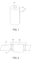
FIG. 1 is a schematic structural diagram of a battery according to an example embodiment; -
FIG. 2 is a partial schematic structural cross-sectional view of a battery according to an example embodiment; -
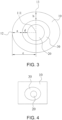
FIG. 3 is a partial schematic structural diagram of a battery according to an example embodiment; and -
FIG. 4 is a partial schematic structural diagram of a battery according to another example embodiment. - 10: battery case; 11: terminal post through hole; 111: center point; 12: first endpoint; 13: second endpoint; 14: first case member; 15: second case member; 20: terminal post; 30: rigid sealing member.
- The technical solutions in the exemplary embodiments of the disclosure will be described clearly and explicitly in conjunction with the drawings in the exemplary embodiments of the disclosure. The description proposed herein is just the exemplary embodiments for the purpose of illustrations only, not intended to limit the scope of the disclosure, so it should be understood that and various modifications and variations could be made thereto without departing from the scope of the disclosure.
- In the description of the disclosure, unless otherwise specifically defined and limited, the terms "first", "second" and the like are only used for illustrative purposes and are not to be construed as expressing or implying a relative importance. The term "plurality" is two or more. The term "and/or" includes any and all combinations of one or more of the associated listed items.
- In particular, a reference to "the" object or "a" and "an" object is intended to denote also one of a possible plurality of such objects. Unless otherwise defined or described, the terms "connect", "fix" should be broadly interpreted, for example, the term "connect" can be "fixedly connect", "detachably connect", "integrally connect", "electrically connect" or "signal connect". The term "connect" also can be "directly connect" or "indirectly connect via a medium". For the persons skilled in the art, the specific meanings of the abovementioned terms in the disclosure can be understood according to the specific situation.
- Further, in the description of the disclosure, it should be understood that spatially relative terms, such as "above", "below" "inside", "outside" and the like, are described based on orientations illustrated in the figures, but are not intended to limit the exemplary embodiments of the disclosure.
- In the context, it should also be understood that when an element or features is provided "outside" or "inside" of another element(s), it can be directly provided "outside" or "inside" of the other element, or be indirectly provided "outside" or "inside" of the another element(s) by an intermediate element.
- One embodiment of the disclosure provides a battery. Referring to
FIG. 1 to FIG. 4 , the battery includes: abattery case 10, where a terminal post throughhole 11 is arranged on thebattery case 10; aterminal post 20, where theterminal post 20 is arranged in the terminal post throughhole 11; and arigid sealing member 30, where a glass transition temperature of therigid sealing member 30 is 300°C to 600°C, and therigid sealing member 30 is at least partially arranged in the terminal post throughhole 11 to seal theterminal post 20 and thebattery case 10. A circumferential outer edge of a surface of thebattery case 10 provided with the terminal post throughhole 11 has afirst endpoint 12 and asecond endpoint 13. Acenter point 111 of the terminal post throughhole 11 forms a first connecting line and a second connecting line respectively with thefirst endpoint 12 and thesecond endpoint 13. The first connecting line is substantially perpendicular to the second connecting line. A distance between thefirst endpoint 12 and a hole wall of the terminal post throughhole 11 along an extending direction of the first connecting line is defined as a, a distance between thesecond endpoint 13 and the hole wall of the terminal post throughhole 11 along an extending direction of the second connecting line is defined as b, and 0.9≤a/b≤1.1. - A battery of one embodiment of the disclosure includes a
battery case 10, aterminal post 20, and arigid sealing member 30. Theterminal post 20 is arranged in a terminal post throughhole 11 on thebattery case 10, and therigid sealing member 30 is at least partially arranged in the terminal post throughhole 11. In this way, theterminal post 20 and thebattery case 10 can be effectively sealed. Since therigid sealing member 30 has a high hardness, problems such as compression deformation failure can be avoided, so that the sealing performance of therigid sealing member 30 between theterminal post 20 and thebattery case 10 can be improved. A circumferential outer edge of a surface of thebattery case 10 provided with the terminal post throughhole 11 has afirst endpoint 12 and asecond endpoint 13. Acenter point 111 of the terminal post throughhole 11 forms a first connecting line and a second connecting line respectively with thefirst endpoint 12 and thesecond endpoint 13. The first connecting line is substantially perpendicular to the second connecting line. A distance between thefirst endpoint 12 and a hole wall of the terminal post throughhole 11 along an extending direction of the first connecting line is defined as a, a distance between thesecond endpoint 13 and the hole wall of the terminal post throughhole 11 along an extending direction of the second connecting line is defined as b, and 0.9≤a/b≤1.1. Therefore, the distances between thefirst endpoint 12 and thesecond endpoint 13 and therigid sealing member 30 are relatively uniform, to ensure that thebattery case 10 can provide relatively balanced compression force to therigid sealing member 30, thereby avoiding the risk of failure of therigid sealing member 30 and improving the safety performance of the battery set. - It should be noted that, in related technologies, a rubber member may be used to seal between a terminal post and a battery case of a battery, and after long-term use, the rubber member deforms due to aging, leading to sealing failure and other problems. In this embodiment, the use of the
rigid sealing member 30 to seal theterminal post 20 and thebattery case 10 can ensure that therigid sealing member 30 effectively seals theterminal post 20 and thebattery case 10 at the initial stage of use. In addition, therigid sealing member 30 is not prone to problems such as aging after long-term use of the battery, thereby avoiding the problem of sealing failure between theterminal post 20 and thebattery case 10 due to the change of the structural performance of therigid sealing member 30. - As the
rigid sealing member 30 has a high hardness, therigid sealing member 30 is not prone to problems such as aging. Correspondingly, the mechanical impact resistance of therigid sealing member 30 may be relatively low. Therefore, it is necessary to avoid the problem of excessive and uneven stress on therigid sealing member 30. In this embodiment, thefirst endpoint 12 and thesecond endpoint 13 of thebattery case 10 that apply an external force to therigid sealing member 30 are arranged to be at approximately the same distance from therigid sealing member 30, so that the problem of excessive and uneven stress on therigid sealing member 30 can be avoided, thereby preventing the rigid sealingmember 30 from cracking under a mechanical impact force to affect the sealing performance of therigid sealing member 30. - A glass transition temperature of the
rigid sealing member 30 is 300°C to 600°C, that is, the temperature at which therigid sealing member 30 starts to soften is 300°C to 600°C, which is a relatively high temperature. Therefore, therigid sealing member 30 is not prone to softening, thereby avoiding the problem of sealing failure during the use of the battery. - As shown in
FIG. 3 , the circumferential outer edge of the surface of thebattery case 10 provided with the terminal post throughhole 11 has thefirst endpoint 12 and thesecond endpoint 13. Thecenter point 111 of the terminal post throughhole 11 forms the first connecting line and the second connecting line respectively with thefirst endpoint 12 and thesecond endpoint 13. The first connecting line is substantially perpendicular to the second connecting line. The first connecting line and the second connecting line are denoted by two dashed lines inFIG. 3 . In addition, the distance between thefirst endpoint 12 and the hole wall of the terminal post throughhole 11 along the extending direction of the first connecting line is defined as a, the distance between thesecond endpoint 13 and the hole wall of the terminal post throughhole 11 along the extending direction of the second connecting line is defined as b, and 0.9≤a/b≤1.1. That is, thefirst endpoint 12 and thesecond endpoint 13 are at approximately the same distance from the rigid sealingmember 30, so the forces applied by thefirst endpoint 12 and thesecond endpoint 13 on the rigid sealingmember 30 are approximately the same, thereby avoiding problems such as cracking of the rigid sealingmember 30 under the forces. - A ratio between the distance a between the
first endpoint 12 and the hole wall of the terminal post throughhole 11 and the distance b between thesecond endpoint 13 and the hole wall of the terminal post throughhole 11 may be 0.9, 0.91, 0.95, 0.96, 0.97, 0.98, 0.99, 1, 1.01, 1.02, 1.03, 1.04, 1.05, 1.06, 1.07, 1.08, 1.09, 1.1, etc. - The
rigid sealing member 30 may be glass, glass-ceramic, ceramic, or other glass- or ceramic-based composite materials, which are not limited herein, to ensure that the rigid sealingmember 30 can have a reliable hardness to avoid problems such as aging. - In one embodiment, a is substantially equal to b. That is, the ratio between the distance a between the
first endpoint 12 and the hole wall of the terminal post throughhole 11 and the distance b between thesecond endpoint 13 and the hole wall of the terminal post throughhole 11 may be 1. Therefore, it can be ensured that the rigid sealingmember 30 receives relatively uniform forces, thereby avoiding the problem of fracture of the rigid sealingmember 30 under the forces, ensuring the sealing performance of the rigid sealingmember 30, and avoiding the problem of sealing failure of the rigid sealingmember 30. - It should be noted that in the disclosure, the term "substantially" means that the determination is made on the basis of considering a machining error, an installation error, a measurement error, and the like. If the machining error, the installation error, the measurement error, and the like are ignored, the first connecting line and the second connecting line may be perpendicular, and a and b may be equal.
- In one embodiment, the circumferential outer edge of the surface of the
battery case 10 provided with the terminal post throughhole 11 may further have a third endpoint. Thecenter point 111 of the terminal post throughhole 11 forms a third connecting line with the third endpoint. The third connecting line may be on the same straight line as the first connecting line. A distance between the third endpoint and the hole wall of the terminal post throughhole 11 along an extending direction of the third connecting line is defined as e, and 0.9≤a/e≤1.1. Further, a/e=1. - In one embodiment, the battery may further include a cell. The cell is arranged in the
battery case 10. The cell may be electrically connected to thebattery case 10, or the cell may be connected to theterminal post 20 on thebattery case 10. - It should be noted that the battery includes a cell and an electrolyte, and is the smallest unit capable of performing an electrochemical reaction such as charging/discharging. The cell is a unit formed by winding or laminating a stack. The stack includes a first electrode plate, a separator, and a second electrode plate. When the first electrode plate is a positive electrode plate, the second electrode plate is a negative electrode plate. The polarities of the first electrode plate and the second electrode plate are interchangeable. The first electrode plate and the second electrode plate are each coated with an active material.
- In one embodiment, as shown in
FIG. 4 , the battery may be a prismatic battery, that is, the battery may be a quadrangular prism battery. The quadrangular prism battery mainly means that the appearance of the battery is of a prism shape, but it is not strictly specified whether each side of the prism must be a straight line in a strict sense. An angle between sides may not be a right angle, but may be a circular are transition. - The battery may be a laminated battery, which can be conveniently formed into a battery module, and can be processed to obtain a battery with a long length. Specifically, the cell is a laminated cell. The cell includes a first electrode plate, a second electrode plate of a polarity opposite to that of the first electrode plate and stacked with the first electrode plate, and a separator arranged between the first electrode plate and the second electrode plate, so that a plurality of pairs of first electrode plates and second electrode plates are stacked to form a laminated cell.
- Alternatively, the battery may be a wound battery, that is, the first electrode plate, the second electrode plate of a polarity opposite to that of the first electrode plate, and the separator arranged between the first electrode plate and the second electrode plate are wound to obtain a wound cell.
- In one embodiment, as shown in
FIG. 1 to FIG. 3 , the battery may be a cylindrical battery. The battery may be a wound battery, that is, the first electrode plate, the second electrode plate of a polarity opposite to that of the first electrode plate, and the separator arranged between the first electrode plate and the second electrode plate are wound to obtain a wound cell. - The surface of the
battery case 10 provided with the terminal post throughhole 11 is a circular surface, the rigid sealingmember 30 effectively seals theterminal post 20 and thebattery case 10, and the circumferential outer surface of the cylindrical battery can provide relatively uniform impact forces to the rigid sealingmember 30, thereby avoiding the problem of fracture of the rigid sealingmember 30 caused by an external force, that is, the rigid sealingmember 30 receives uniform forces during the sealing process, thereby realizing good sealing and improving the connection strength between the rigid sealingmember 30 and thebattery case 10. - In one embodiment, a diameter of the cylindrical battery is greater than or equal to 20 mm, to ensure that the cylindrical battery can have a reliable capacity, thereby ensuring the service performance of the cylindrical battery.
- In one embodiment, a distance between the
center point 111 and thefirst endpoint 12 is defined as c, a thickness of the rigid sealingmember 30 in the terminal post throughhole 11 along the extending direction of the first connecting line is defined as d, and 3%≤d/c≤20%. This not only ensures that the rigid sealingmember 30 has a reliable structural strength, but also ensures that theterminal post 20 can have a reliable current flow area, thereby ensuring the safe use of the battery. - If a ratio between the thickness d of the rigid sealing
member 30 in the terminal post throughhole 11 and the distance c between thecenter point 111 and thefirst endpoint 12 is less than 3%, the overall strength of the rigid sealingmember 30 will be insufficient, affecting the sealing and insulation performance between theterminal post 20 and thebattery case 10. If the ratio between the thickness d of the rigid sealingmember 30 in the terminal post throughhole 11 and the distance c between thecenter point 111 and thefirst endpoint 12 is greater than 20%, the current flow area of theterminal post 20 is insufficient, affecting the electron transmission rate of the battery. In this case, an outer end of thebattery case 10 is close to the rigid sealing member, leading to impact on thebattery case 10, and resulting in the risk of failure of the rigid sealingmember 30 within a short time. - As shown in
FIG. 3 , the distance between thecenter point 111 and thefirst endpoint 12 is defined as c, and the thickness of the rigid sealingmember 30 in the terminal post throughhole 11 along the extending direction of the first connecting line is defined as d. - The ratio between the thickness d of the rigid sealing
member 30 in the terminal post throughhole 11 and the distance c between thecenter point 111 and thefirst endpoint 12 may be 3%, 3.1%, 3.2%, 3.3%, 3.4%, 3.5%, 4%, 4.5%, 5%, 5.5%, 6%, 6.5%, 7%, 7.5%, 8%, 9%, 9.5%, 10%, 11%, 12%, 13%, 14%, 15%, 15.5%, 16%, 17%, 18%, 19%, 19.5%, 19.8%, 19.9%, 20%, etc. - In one embodiment, the rigid sealing
member 30 includes glass, ceramic, or glass-ceramic, to avoid aging of the rigid sealingmember 30. In addition, problems such as damage to the rigid sealingmember 30 can be avoided by controlling the uniformity of forces applied by thebattery case 10 to theterminal post 20, thereby ensuring the sealing performance of the rigid sealingmember 30. - In one embodiment, the rigid sealing
member 30 is an annular sealing structure, to reliably seal theterminal post 20 and thebattery case 10 and avoid problems such as sealing failure between theterminal post 20 and thebattery case 10. - The terminal post through
hole 11 may be a polygonal hole. For example, the terminal post throughhole 11 may be a rectangular hole. A circumferential outer surface of the annular sealing structure formed by the rigid sealingmember 30 may be rectangular, and the portion of theterminal post 20 located in the terminal post throughhole 11 may be a cylindrical structure, a rectangular structure, etc., which is not limited herein. - In one embodiment, the rigid sealing
member 30 includes a circular sealing structure. This not only simplifies the structure, but also realizes reliable sealing between theterminal post 20 and thebattery case 10. In addition, the circular sealing structure is not prone to stress concentration, and protects the rigid sealingmember 30 from structural damage caused by a mechanical impact force, to ensure the structural strength of the rigid sealingmember 30, thereby ensuring reliable sealing between thebattery case 10 and theterminal post 20 by the rigid sealingmember 30. - In one embodiment, as shown in
FIG. 1 , thebattery case 10 includes afirst case member 14 and asecond case member 15 connected to each other. Thefirst case member 14 is a flat plate, thesecond case member 15 is formed with an accommodation cavity, and the arrangement of the terminal post throughhole 11 on the flat plate not only simplifies the structure, but also facilitates the arrangement of theterminal post 20 on thebattery case 10, thereby improving the installation efficiency of the battery. - In one embodiment, the
first case member 14 may be formed with an accommodation cavity, thesecond case member 15 may be formed with an accommodation cavity, and theterminal post 20 may be arranged on thefirst case member 14 or thesecond case member 15. Alternatively, there are twoterminal posts 20, and the twoterminal posts 20 may be arranged on thefirst case member 14 and thesecond case member 15 respectively. - It should be noted that the number of
terminal posts 20 may be one, theterminal post 20 may be electrically connected to one tab of the cell, and another tab of the cell may be electrically connected to thebattery case 10, in which case thebattery case 10 may be insulated from theterminal post 20. The number ofterminal posts 20 may be two, and the twoterminal posts 20 may be arranged on the same side of thebattery case 10. For example, the twoterminal posts 20 may both be arranged on the flat plate. Alternatively, the twoterminal posts 20 may be arranged on two opposite sides of thebattery case 10 respectively. - In one embodiment, the
battery case 10 is a metal piece, to ensure the structural strength of thebattery case 10 and facilitate the installation of the rigid sealingmember 30, thereby improving the reliable sealing between theterminal post 20 and thebattery case 10 by the rigid sealingmember 30. - The
battery case 10 may be made of steel, aluminum, copper, or a combination thereof, which is not limited herein. - It should be noted that the
first case member 14 and thesecond case member 15 may be independently arranged. In some embodiments, thefirst case member 14 and thesecond case member 15 may be integrally formed, a space for accommodating the cell is formed by stamping, and then a sealed connection is achieved by welding. - In one embodiment, the rigid sealing
member 30 is hot-melted in the terminal post throughhole 11, to ensure that the rigid sealingmember 30 reliably seals theterminal post 20 and thebattery case 10, and improve the efficiency of fabrication and installation of the rigid sealingmember 30, thereby improving the installation efficiency of the battery. - In one embodiment, the rigid sealing
member 30 may be entirely located in the terminal post throughhole 11, that is, an upper surface of the rigid sealingmember 30 may be lower than an outer surface of thebattery case 10, or the upper surface of the rigid sealingmember 30 may be even with the outer surface of thebattery case 10. - In one embodiment, as shown in
FIG. 2 , one part of the rigid sealingmember 30 may be located inside the terminal post throughhole 11, and the other part of the rigid sealingmember 30 may be located outside the terminal post throughhole 11, so that the sealing performance of the rigid sealingmember 30 can be improved. - One embodiment of the disclosure further provides a battery set, including the battery described above.
- A battery set of one embodiment of the disclosure includes a battery. The battery includes a
battery case 10, aterminal post 20, and arigid sealing member 30. Theterminal post 20 is arranged in a terminal post throughhole 11 on thebattery case 10, and the rigid sealingmember 30 is at least partially arranged in the terminal post throughhole 11. In this way, theterminal post 20 and thebattery case 10 can be effectively sealed. Since the rigid sealingmember 30 has a high hardness, problems such as compression deformation failure can be avoided, so that the sealing performance of the rigid sealingmember 30 between theterminal post 20 and thebattery case 10 can be improved. A circumferential outer edge of a surface of thebattery case 10 provided with the terminal post throughhole 11 has afirst endpoint 12 and asecond endpoint 13. Acenter point 111 of the terminal post throughhole 11 forms a first connecting line and a second connecting line respectively with thefirst endpoint 12 and thesecond endpoint 13. The first connecting line is substantially perpendicular to the second connecting line. A distance between thefirst endpoint 12 and a hole wall of the terminal post throughhole 11 along an extending direction of the first connecting line is defined as a, a distance between thesecond endpoint 13 and the hole wall of the terminal post throughhole 11 along an extending direction of the second connecting line is defined as b, and 0.9≤a/b≤1.1. Therefore, the distances between thefirst endpoint 12 and thesecond endpoint 13 and the rigid sealingmember 30 are relatively uniform, to ensure that thebattery case 10 can provide relatively balanced compression force to the rigid sealingmember 30, thereby avoiding the risk of failure of the rigid sealingmember 30 and improving the safety performance of the battery. - In one embodiment, the battery set is a battery module or a battery pack.
- The battery module includes a plurality of batteries. The batteries may be prismatic batteries, and the battery module may further include end plates and side plates for fixing the plurality of batteries. The batteries may be cylindrical batteries, and the battery module may further include a tray. The batteries may be fixed on the tray.
- The battery pack includes a plurality of batteries and a casing for fixing the plurality of batteries.
- It should be noted that the battery pack may include a plurality of batteries, and the plurality of batteries are arranged in the casing. The plurality of batteries may be formed into a battery module and then be installed in the casing. Alternatively, the plurality of batteries may be directly arranged in the casing without being formed into a battery module, and the plurality of batteries are fixed by the casing.
- Other embodiments of the disclosure will be apparent to those skilled in the art from consideration of the specification and practice of the disclosure disclosed herein. The disclosure is intended to cover any variations, uses or adaptations of the disclosure. These variations, uses, or adaptations follow the general principles of the disclosure and include common general knowledge or conventional technical means in the art that are not disclosed in the disclosure. The specification and embodiments are illustrative, and the real scope and spirit of the disclosure is defined by the appended claims.
- It should be understood that the disclosure is not limited to the precise structures that have been described above and shown in the drawings, and various modifications and variations can be made without departing from the scope thereof. The scope of the disclosure is limited only by the appended claims.
Claims (12)
- A battery, characterized by comprising:a battery case (10), wherein a terminal post through hole (11) is arranged on the battery case (10);a terminal post (20), wherein the terminal post (20) is arranged in the terminal post through hole (11); anda rigid sealing member (30), wherein a glass transition temperature of the rigid sealing member (30) is 300°C to 600°C, and the rigid sealing member (30) is at least partially arranged in the terminal post through hole (11) to seal the terminal post (20) and the battery case (10),wherein, a circumferential outer edge of a surface of the battery case (10) provided with the terminal post through hole (11) has a first endpoint (12) and a second endpoint (13), a center point (111) of the terminal post through hole (11) forms a first connecting line and a second connecting line respectively with the first endpoint (12) and the second endpoint (13), the first connecting line is substantially perpendicular to the second connecting line, a distance between the first endpoint (12) and a hole wall of the terminal post through hole (11) along an extending direction of the first connecting line is defined as a, a distance between the second endpoint (13) and the hole wall of the terminal post through hole (11) along an extending direction of the second connecting line is defined as b, and 0.9≤a/b≤1.1.
- The battery according to claim 1, characterized in that, a is substantially equal to b.
- The battery according to claim 1, characterized in that, the surface of the battery case (10) provided with the terminal post through hole (11) is a circular surface.
- The battery according to claim 3, characterized in that, a distance between the center point (111) and the first endpoint (12) is defined as c, a thickness of the rigid sealing member (30) in the terminal post through hole (11) along the extending direction of the first connecting line is defined as d, and 3%≤d/c≤20%.
- The battery according to claim 1, characterized in that, the rigid sealing member (30) comprises glass, ceramic, or glass-ceramic.
- The battery according to claim 1, characterized in that, the rigid sealing member (30) is an annular sealing structure.
- The battery according to claim 6, characterized in that, the rigid sealing member (30) comprises a circular sealing structure.
- The battery according to any one of claims 1 to 7, characterized in that, the battery is a cylindrical battery.
- The battery according to claim 8, characterized in that, a diameter of the cylindrical battery is greater than or equal to 20 mm.
- The battery according to any one of claims 1 to 7, characterized in that, the battery case (10) comprises a first case member (14) and a second case member (15) connected to each other, the first case member (14) is a flat plate, the second case member (15) is formed with an accommodation cavity, and
the terminal post through hole (11) is arranged on the flat plate. - The battery according to any one of claims 1 to 7, characterized in that, the battery case (10) is a metal piece.
- The battery according to any one of claims 1 to 7, characterized in that, the rigid sealing member (30) is hot-melted in the terminal post through hole (11).
Applications Claiming Priority (1)
| Application Number | Priority Date | Filing Date | Title |
|---|---|---|---|
| CN202211733909.9A CN115966821A (en) | 2022-12-30 | 2022-12-30 | Battery |
Publications (2)
| Publication Number | Publication Date |
|---|---|
| EP4395020A2 true EP4395020A2 (en) | 2024-07-03 |
| EP4395020A3 EP4395020A3 (en) | 2024-07-10 |
Family
ID=85889490
Family Applications (1)
| Application Number | Title | Priority Date | Filing Date |
|---|---|---|---|
| EP23175539.8A Withdrawn EP4395020A3 (en) | 2022-12-30 | 2023-05-26 | Battery |
Country Status (2)
| Country | Link |
|---|---|
| EP (1) | EP4395020A3 (en) |
| CN (1) | CN115966821A (en) |
Family Cites Families (4)
| Publication number | Priority date | Publication date | Assignee | Title |
|---|---|---|---|---|
| US20080085451A1 (en) * | 2006-10-06 | 2008-04-10 | Greatbatch Ltd. | Highly Compact Electrochemical Cell |
| DE102013006463B4 (en) * | 2013-04-15 | 2017-01-19 | Schott Ag | execution |
| CN217589378U (en) * | 2022-06-28 | 2022-10-14 | 中创新航科技股份有限公司 | Battery with a battery cell |
| CN219086103U (en) * | 2022-12-30 | 2023-05-26 | 中创新航科技股份有限公司 | Battery |
-
2022
- 2022-12-30 CN CN202211733909.9A patent/CN115966821A/en active Pending
-
2023
- 2023-05-26 EP EP23175539.8A patent/EP4395020A3/en not_active Withdrawn
Also Published As
| Publication number | Publication date |
|---|---|
| EP4395020A3 (en) | 2024-07-10 |
| CN115966821A (en) | 2023-04-14 |
Similar Documents
| Publication | Publication Date | Title |
|---|---|---|
| KR101066257B1 (en) | Cylindrical secondary battery | |
| EP2733778B1 (en) | Jelly-roll with improved processability and battery cell including same | |
| KR102361705B1 (en) | Rechargeable battery having cover | |
| EP4343931A1 (en) | Battery | |
| CN114497904A (en) | Battery assembly method and battery | |
| CN114678594A (en) | Battery | |
| CN114614208A (en) | Battery with a battery cell | |
| WO2019103393A1 (en) | Electrode assembly having improved safety of use by means of outermost electrode structure and current collector material, and lithium-ion secondary battery having same | |
| CN114614209A (en) | Battery with a battery cell | |
| EP4386950A1 (en) | Battery pack | |
| CN218448353U (en) | Single battery | |
| EP4395020A2 (en) | Battery | |
| CN216720097U (en) | Battery cover plate assembly, battery and battery pack | |
| CN217086806U (en) | Battery and battery pack | |
| CN219086103U (en) | Battery | |
| CN114725477A (en) | Battery cell unit, battery and assembly method of battery | |
| JP2011077019A (en) | Secondary battery | |
| CN219476835U (en) | Batteries and Battery Packs | |
| CN218448331U (en) | Battery | |
| CN217823030U (en) | Battery cover plate assembly and battery | |
| CN218731628U (en) | Battery | |
| CN218448366U (en) | Single battery | |
| CN218957858U (en) | Battery | |
| CN216980648U (en) | Battery cell unit and battery | |
| CN218101465U (en) | Battery |
Legal Events
| Date | Code | Title | Description |
|---|---|---|---|
| PUAI | Public reference made under article 153(3) epc to a published international application that has entered the european phase |
Free format text: ORIGINAL CODE: 0009012 |
|
| STAA | Information on the status of an ep patent application or granted ep patent |
Free format text: STATUS: REQUEST FOR EXAMINATION WAS MADE |
|
| PUAL | Search report despatched |
Free format text: ORIGINAL CODE: 0009013 |
|
| 17P | Request for examination filed |
Effective date: 20230526 |
|
| AK | Designated contracting states |
Kind code of ref document: A2 Designated state(s): AL AT BE BG CH CY CZ DE DK EE ES FI FR GB GR HR HU IE IS IT LI LT LU LV MC ME MK MT NL NO PL PT RO RS SE SI SK SM TR |
|
| AK | Designated contracting states |
Kind code of ref document: A3 Designated state(s): AL AT BE BG CH CY CZ DE DK EE ES FI FR GB GR HR HU IE IS IT LI LT LU LV MC ME MK MT NL NO PL PT RO RS SE SI SK SM TR |
|
| RIC1 | Information provided on ipc code assigned before grant |
Ipc: H01M 50/559 20210101ALI20240604BHEP Ipc: H01M 50/191 20210101ALI20240604BHEP Ipc: H01M 50/179 20210101ALI20240604BHEP Ipc: H01M 50/119 20210101ALI20240604BHEP Ipc: H01M 50/107 20210101AFI20240604BHEP |
|
| STAA | Information on the status of an ep patent application or granted ep patent |
Free format text: STATUS: THE APPLICATION IS DEEMED TO BE WITHDRAWN |
|
| 18D | Application deemed to be withdrawn |
Effective date: 20250111 |