EP4395010A1 - Fire spreading prevention unit and battery provided with same - Google Patents
Fire spreading prevention unit and battery provided with same Download PDFInfo
- Publication number
- EP4395010A1 EP4395010A1 EP21955068.8A EP21955068A EP4395010A1 EP 4395010 A1 EP4395010 A1 EP 4395010A1 EP 21955068 A EP21955068 A EP 21955068A EP 4395010 A1 EP4395010 A1 EP 4395010A1
- Authority
- EP
- European Patent Office
- Prior art keywords
- thermally conductive
- sheet
- fire spreading
- spreading prevention
- sheets
- Prior art date
- Legal status (The legal status is an assumption and is not a legal conclusion. Google has not performed a legal analysis and makes no representation as to the accuracy of the status listed.)
- Pending
Links
- 238000003892 spreading Methods 0.000 title claims abstract description 168
- 230000002265 prevention Effects 0.000 title claims abstract description 163
- 229920001971 elastomer Polymers 0.000 claims abstract description 84
- 239000005060 rubber Substances 0.000 claims abstract description 83
- 238000010030 laminating Methods 0.000 claims abstract description 9
- OKTJSMMVPCPJKN-UHFFFAOYSA-N Carbon Chemical compound [C] OKTJSMMVPCPJKN-UHFFFAOYSA-N 0.000 claims description 19
- 239000000463 material Substances 0.000 claims description 16
- 239000000454 talc Substances 0.000 claims description 13
- 229910052623 talc Inorganic materials 0.000 claims description 13
- 239000011347 resin Substances 0.000 claims description 12
- 229920005989 resin Polymers 0.000 claims description 12
- 239000010439 graphite Substances 0.000 claims description 9
- 229910002804 graphite Inorganic materials 0.000 claims description 9
- VYPSYNLAJGMNEJ-UHFFFAOYSA-N Silicium dioxide Chemical compound O=[Si]=O VYPSYNLAJGMNEJ-UHFFFAOYSA-N 0.000 claims description 8
- 239000011231 conductive filler Substances 0.000 claims description 7
- 238000001816 cooling Methods 0.000 claims description 7
- 229910052782 aluminium Inorganic materials 0.000 claims description 6
- -1 aluminum compound Chemical class 0.000 claims description 6
- 239000000377 silicon dioxide Substances 0.000 claims description 4
- 230000000149 penetrating effect Effects 0.000 claims description 3
- 238000000034 method Methods 0.000 description 13
- 229910052799 carbon Inorganic materials 0.000 description 10
- 230000004048 modification Effects 0.000 description 9
- 238000012986 modification Methods 0.000 description 9
- 150000001875 compounds Chemical class 0.000 description 6
- 239000000945 filler Substances 0.000 description 6
- 229920002379 silicone rubber Polymers 0.000 description 5
- 239000004945 silicone rubber Substances 0.000 description 5
- 230000000694 effects Effects 0.000 description 4
- 229910052751 metal Inorganic materials 0.000 description 4
- 239000002184 metal Substances 0.000 description 4
- 239000004820 Pressure-sensitive adhesive Substances 0.000 description 3
- 239000000853 adhesive Substances 0.000 description 3
- 230000001070 adhesive effect Effects 0.000 description 3
- 239000002390 adhesive tape Substances 0.000 description 3
- PNEYBMLMFCGWSK-UHFFFAOYSA-N aluminium oxide Inorganic materials [O-2].[O-2].[O-2].[Al+3].[Al+3] PNEYBMLMFCGWSK-UHFFFAOYSA-N 0.000 description 3
- 239000000919 ceramic Substances 0.000 description 3
- 239000002826 coolant Substances 0.000 description 3
- 229910052593 corundum Inorganic materials 0.000 description 3
- 238000002788 crimping Methods 0.000 description 3
- 239000000779 smoke Substances 0.000 description 3
- 229910001845 yogo sapphire Inorganic materials 0.000 description 3
- KAKZBPTYRLMSJV-UHFFFAOYSA-N Butadiene Chemical compound C=CC=C KAKZBPTYRLMSJV-UHFFFAOYSA-N 0.000 description 2
- XEEYBQQBJWHFJM-UHFFFAOYSA-N Iron Chemical compound [Fe] XEEYBQQBJWHFJM-UHFFFAOYSA-N 0.000 description 2
- HBBGRARXTFLTSG-UHFFFAOYSA-N Lithium ion Chemical compound [Li+] HBBGRARXTFLTSG-UHFFFAOYSA-N 0.000 description 2
- PXHVJJICTQNCMI-UHFFFAOYSA-N Nickel Chemical compound [Ni] PXHVJJICTQNCMI-UHFFFAOYSA-N 0.000 description 2
- 229920000459 Nitrile rubber Polymers 0.000 description 2
- PPBRXRYQALVLMV-UHFFFAOYSA-N Styrene Chemical compound C=CC1=CC=CC=C1 PPBRXRYQALVLMV-UHFFFAOYSA-N 0.000 description 2
- GWEVSGVZZGPLCZ-UHFFFAOYSA-N Titan oxide Chemical compound O=[Ti]=O GWEVSGVZZGPLCZ-UHFFFAOYSA-N 0.000 description 2
- MCMNRKCIXSYSNV-UHFFFAOYSA-N Zirconium dioxide Chemical compound O=[Zr]=O MCMNRKCIXSYSNV-UHFFFAOYSA-N 0.000 description 2
- XAGFODPZIPBFFR-UHFFFAOYSA-N aluminium Chemical compound [Al] XAGFODPZIPBFFR-UHFFFAOYSA-N 0.000 description 2
- 229920006231 aramid fiber Polymers 0.000 description 2
- UORVGPXVDQYIDP-UHFFFAOYSA-N borane Chemical compound B UORVGPXVDQYIDP-UHFFFAOYSA-N 0.000 description 2
- 239000003795 chemical substances by application Substances 0.000 description 2
- 239000000470 constituent Substances 0.000 description 2
- 239000012535 impurity Substances 0.000 description 2
- 238000009413 insulation Methods 0.000 description 2
- 229910001416 lithium ion Inorganic materials 0.000 description 2
- HCWCAKKEBCNQJP-UHFFFAOYSA-N magnesium orthosilicate Chemical compound [Mg+2].[Mg+2].[O-][Si]([O-])([O-])[O-] HCWCAKKEBCNQJP-UHFFFAOYSA-N 0.000 description 2
- 238000002360 preparation method Methods 0.000 description 2
- 239000000758 substrate Substances 0.000 description 2
- RNFJDJUURJAICM-UHFFFAOYSA-N 2,2,4,4,6,6-hexaphenoxy-1,3,5-triaza-2$l^{5},4$l^{5},6$l^{5}-triphosphacyclohexa-1,3,5-triene Chemical compound N=1P(OC=2C=CC=CC=2)(OC=2C=CC=CC=2)=NP(OC=2C=CC=CC=2)(OC=2C=CC=CC=2)=NP=1(OC=1C=CC=CC=1)OC1=CC=CC=C1 RNFJDJUURJAICM-UHFFFAOYSA-N 0.000 description 1
- 229910017083 AlN Inorganic materials 0.000 description 1
- 229930091051 Arenine Natural products 0.000 description 1
- 229920002943 EPDM rubber Polymers 0.000 description 1
- 239000004593 Epoxy Substances 0.000 description 1
- 229920000181 Ethylene propylene rubber Polymers 0.000 description 1
- YCKRFDGAMUMZLT-UHFFFAOYSA-N Fluorine atom Chemical compound [F] YCKRFDGAMUMZLT-UHFFFAOYSA-N 0.000 description 1
- 244000043261 Hevea brasiliensis Species 0.000 description 1
- BLRPTPMANUNPDV-UHFFFAOYSA-N Silane Chemical compound [SiH4] BLRPTPMANUNPDV-UHFFFAOYSA-N 0.000 description 1
- RTAQQCXQSZGOHL-UHFFFAOYSA-N Titanium Chemical compound [Ti] RTAQQCXQSZGOHL-UHFFFAOYSA-N 0.000 description 1
- 229920006311 Urethane elastomer Polymers 0.000 description 1
- 150000001336 alkenes Chemical class 0.000 description 1
- 239000000956 alloy Substances 0.000 description 1
- 229910045601 alloy Inorganic materials 0.000 description 1
- 238000005452 bending Methods 0.000 description 1
- 229910000085 borane Inorganic materials 0.000 description 1
- KGBXLFKZBHKPEV-UHFFFAOYSA-N boric acid Chemical compound OB(O)O KGBXLFKZBHKPEV-UHFFFAOYSA-N 0.000 description 1
- 239000004327 boric acid Substances 0.000 description 1
- 239000003990 capacitor Substances 0.000 description 1
- 229910017052 cobalt Inorganic materials 0.000 description 1
- 239000010941 cobalt Substances 0.000 description 1
- GUTLYIVDDKVIGB-UHFFFAOYSA-N cobalt atom Chemical compound [Co] GUTLYIVDDKVIGB-UHFFFAOYSA-N 0.000 description 1
- 239000000498 cooling water Substances 0.000 description 1
- 229910052802 copper Inorganic materials 0.000 description 1
- 229910052878 cordierite Inorganic materials 0.000 description 1
- 230000008878 coupling Effects 0.000 description 1
- 238000010168 coupling process Methods 0.000 description 1
- 238000005859 coupling reaction Methods 0.000 description 1
- 230000000994 depressogenic effect Effects 0.000 description 1
- JSKIRARMQDRGJZ-UHFFFAOYSA-N dimagnesium dioxido-bis[(1-oxido-3-oxo-2,4,6,8,9-pentaoxa-1,3-disila-5,7-dialuminabicyclo[3.3.1]nonan-7-yl)oxy]silane Chemical compound [Mg++].[Mg++].[O-][Si]([O-])(O[Al]1O[Al]2O[Si](=O)O[Si]([O-])(O1)O2)O[Al]1O[Al]2O[Si](=O)O[Si]([O-])(O1)O2 JSKIRARMQDRGJZ-UHFFFAOYSA-N 0.000 description 1
- KZHJGOXRZJKJNY-UHFFFAOYSA-N dioxosilane;oxo(oxoalumanyloxy)alumane Chemical compound O=[Si]=O.O=[Si]=O.O=[Al]O[Al]=O.O=[Al]O[Al]=O.O=[Al]O[Al]=O KZHJGOXRZJKJNY-UHFFFAOYSA-N 0.000 description 1
- 238000007599 discharging Methods 0.000 description 1
- 239000000806 elastomer Substances 0.000 description 1
- 150000002148 esters Chemical class 0.000 description 1
- 238000004880 explosion Methods 0.000 description 1
- 230000005294 ferromagnetic effect Effects 0.000 description 1
- 239000003063 flame retardant Substances 0.000 description 1
- 239000011737 fluorine Substances 0.000 description 1
- 229910052731 fluorine Inorganic materials 0.000 description 1
- 229910052839 forsterite Inorganic materials 0.000 description 1
- 238000009434 installation Methods 0.000 description 1
- 229910052742 iron Inorganic materials 0.000 description 1
- UQSXHKLRYXJYBZ-UHFFFAOYSA-N iron oxide Inorganic materials [Fe]=O UQSXHKLRYXJYBZ-UHFFFAOYSA-N 0.000 description 1
- 239000012948 isocyanate Substances 0.000 description 1
- 150000002513 isocyanates Chemical class 0.000 description 1
- 229920003049 isoprene rubber Polymers 0.000 description 1
- 238000003475 lamination Methods 0.000 description 1
- 239000000391 magnesium silicate Substances 0.000 description 1
- 229910052919 magnesium silicate Inorganic materials 0.000 description 1
- 235000019792 magnesium silicate Nutrition 0.000 description 1
- 229910052863 mullite Inorganic materials 0.000 description 1
- 229920003052 natural elastomer Polymers 0.000 description 1
- 229920001194 natural rubber Polymers 0.000 description 1
- 229910052759 nickel Inorganic materials 0.000 description 1
- JRZJOMJEPLMPRA-UHFFFAOYSA-N olefin Natural products CCCCCCCC=C JRZJOMJEPLMPRA-UHFFFAOYSA-N 0.000 description 1
- NDLPOXTZKUMGOV-UHFFFAOYSA-N oxo(oxoferriooxy)iron hydrate Chemical compound O.O=[Fe]O[Fe]=O NDLPOXTZKUMGOV-UHFFFAOYSA-N 0.000 description 1
- 239000002245 particle Substances 0.000 description 1
- 230000001681 protective effect Effects 0.000 description 1
- 239000011819 refractory material Substances 0.000 description 1
- 229910000077 silane Inorganic materials 0.000 description 1
- 239000007787 solid Substances 0.000 description 1
- 229920003048 styrene butadiene rubber Polymers 0.000 description 1
- 238000004381 surface treatment Methods 0.000 description 1
- 229920002725 thermoplastic elastomer Polymers 0.000 description 1
- 229920001187 thermosetting polymer Polymers 0.000 description 1
- JOYRKODLDBILNP-UHFFFAOYSA-N urethane group Chemical group NC(=O)OCC JOYRKODLDBILNP-UHFFFAOYSA-N 0.000 description 1
- 238000003466 welding Methods 0.000 description 1
Images







Classifications
-
- H—ELECTRICITY
- H01—ELECTRIC ELEMENTS
- H01M—PROCESSES OR MEANS, e.g. BATTERIES, FOR THE DIRECT CONVERSION OF CHEMICAL ENERGY INTO ELECTRICAL ENERGY
- H01M50/00—Constructional details or processes of manufacture of the non-active parts of electrochemical cells other than fuel cells, e.g. hybrid cells
- H01M50/20—Mountings; Secondary casings or frames; Racks, modules or packs; Suspension devices; Shock absorbers; Transport or carrying devices; Holders
- H01M50/204—Racks, modules or packs for multiple batteries or multiple cells
-
- H—ELECTRICITY
- H01—ELECTRIC ELEMENTS
- H01M—PROCESSES OR MEANS, e.g. BATTERIES, FOR THE DIRECT CONVERSION OF CHEMICAL ENERGY INTO ELECTRICAL ENERGY
- H01M10/00—Secondary cells; Manufacture thereof
- H01M10/60—Heating or cooling; Temperature control
- H01M10/61—Types of temperature control
- H01M10/613—Cooling or keeping cold
-
- H—ELECTRICITY
- H01—ELECTRIC ELEMENTS
- H01M—PROCESSES OR MEANS, e.g. BATTERIES, FOR THE DIRECT CONVERSION OF CHEMICAL ENERGY INTO ELECTRICAL ENERGY
- H01M10/00—Secondary cells; Manufacture thereof
- H01M10/60—Heating or cooling; Temperature control
- H01M10/62—Heating or cooling; Temperature control specially adapted for specific applications
- H01M10/625—Vehicles
-
- H—ELECTRICITY
- H01—ELECTRIC ELEMENTS
- H01M—PROCESSES OR MEANS, e.g. BATTERIES, FOR THE DIRECT CONVERSION OF CHEMICAL ENERGY INTO ELECTRICAL ENERGY
- H01M10/00—Secondary cells; Manufacture thereof
- H01M10/60—Heating or cooling; Temperature control
- H01M10/64—Heating or cooling; Temperature control characterised by the shape of the cells
- H01M10/647—Prismatic or flat cells, e.g. pouch cells
-
- H—ELECTRICITY
- H01—ELECTRIC ELEMENTS
- H01M—PROCESSES OR MEANS, e.g. BATTERIES, FOR THE DIRECT CONVERSION OF CHEMICAL ENERGY INTO ELECTRICAL ENERGY
- H01M10/00—Secondary cells; Manufacture thereof
- H01M10/60—Heating or cooling; Temperature control
- H01M10/65—Means for temperature control structurally associated with the cells
- H01M10/653—Means for temperature control structurally associated with the cells characterised by electrically insulating or thermally conductive materials
-
- H—ELECTRICITY
- H01—ELECTRIC ELEMENTS
- H01M—PROCESSES OR MEANS, e.g. BATTERIES, FOR THE DIRECT CONVERSION OF CHEMICAL ENERGY INTO ELECTRICAL ENERGY
- H01M10/00—Secondary cells; Manufacture thereof
- H01M10/60—Heating or cooling; Temperature control
- H01M10/65—Means for temperature control structurally associated with the cells
- H01M10/655—Solid structures for heat exchange or heat conduction
-
- H—ELECTRICITY
- H01—ELECTRIC ELEMENTS
- H01M—PROCESSES OR MEANS, e.g. BATTERIES, FOR THE DIRECT CONVERSION OF CHEMICAL ENERGY INTO ELECTRICAL ENERGY
- H01M10/00—Secondary cells; Manufacture thereof
- H01M10/60—Heating or cooling; Temperature control
- H01M10/65—Means for temperature control structurally associated with the cells
- H01M10/655—Solid structures for heat exchange or heat conduction
- H01M10/6551—Surfaces specially adapted for heat dissipation or radiation, e.g. fins or coatings
-
- H—ELECTRICITY
- H01—ELECTRIC ELEMENTS
- H01M—PROCESSES OR MEANS, e.g. BATTERIES, FOR THE DIRECT CONVERSION OF CHEMICAL ENERGY INTO ELECTRICAL ENERGY
- H01M10/00—Secondary cells; Manufacture thereof
- H01M10/60—Heating or cooling; Temperature control
- H01M10/65—Means for temperature control structurally associated with the cells
- H01M10/655—Solid structures for heat exchange or heat conduction
- H01M10/6554—Rods or plates
- H01M10/6555—Rods or plates arranged between the cells
-
- H—ELECTRICITY
- H01—ELECTRIC ELEMENTS
- H01M—PROCESSES OR MEANS, e.g. BATTERIES, FOR THE DIRECT CONVERSION OF CHEMICAL ENERGY INTO ELECTRICAL ENERGY
- H01M10/00—Secondary cells; Manufacture thereof
- H01M10/60—Heating or cooling; Temperature control
- H01M10/65—Means for temperature control structurally associated with the cells
- H01M10/658—Means for temperature control structurally associated with the cells by thermal insulation or shielding
-
- H—ELECTRICITY
- H01—ELECTRIC ELEMENTS
- H01M—PROCESSES OR MEANS, e.g. BATTERIES, FOR THE DIRECT CONVERSION OF CHEMICAL ENERGY INTO ELECTRICAL ENERGY
- H01M50/00—Constructional details or processes of manufacture of the non-active parts of electrochemical cells other than fuel cells, e.g. hybrid cells
- H01M50/20—Mountings; Secondary casings or frames; Racks, modules or packs; Suspension devices; Shock absorbers; Transport or carrying devices; Holders
-
- H—ELECTRICITY
- H01—ELECTRIC ELEMENTS
- H01M—PROCESSES OR MEANS, e.g. BATTERIES, FOR THE DIRECT CONVERSION OF CHEMICAL ENERGY INTO ELECTRICAL ENERGY
- H01M50/00—Constructional details or processes of manufacture of the non-active parts of electrochemical cells other than fuel cells, e.g. hybrid cells
- H01M50/20—Mountings; Secondary casings or frames; Racks, modules or packs; Suspension devices; Shock absorbers; Transport or carrying devices; Holders
- H01M50/218—Mountings; Secondary casings or frames; Racks, modules or packs; Suspension devices; Shock absorbers; Transport or carrying devices; Holders characterised by the material
- H01M50/22—Mountings; Secondary casings or frames; Racks, modules or packs; Suspension devices; Shock absorbers; Transport or carrying devices; Holders characterised by the material of the casings or racks
- H01M50/231—Mountings; Secondary casings or frames; Racks, modules or packs; Suspension devices; Shock absorbers; Transport or carrying devices; Holders characterised by the material of the casings or racks having a layered structure
-
- H—ELECTRICITY
- H01—ELECTRIC ELEMENTS
- H01M—PROCESSES OR MEANS, e.g. BATTERIES, FOR THE DIRECT CONVERSION OF CHEMICAL ENERGY INTO ELECTRICAL ENERGY
- H01M50/00—Constructional details or processes of manufacture of the non-active parts of electrochemical cells other than fuel cells, e.g. hybrid cells
- H01M50/20—Mountings; Secondary casings or frames; Racks, modules or packs; Suspension devices; Shock absorbers; Transport or carrying devices; Holders
- H01M50/233—Mountings; Secondary casings or frames; Racks, modules or packs; Suspension devices; Shock absorbers; Transport or carrying devices; Holders characterised by physical properties of casings or racks, e.g. dimensions
- H01M50/24—Mountings; Secondary casings or frames; Racks, modules or packs; Suspension devices; Shock absorbers; Transport or carrying devices; Holders characterised by physical properties of casings or racks, e.g. dimensions adapted for protecting batteries from their environment, e.g. from corrosion
-
- Y—GENERAL TAGGING OF NEW TECHNOLOGICAL DEVELOPMENTS; GENERAL TAGGING OF CROSS-SECTIONAL TECHNOLOGIES SPANNING OVER SEVERAL SECTIONS OF THE IPC; TECHNICAL SUBJECTS COVERED BY FORMER USPC CROSS-REFERENCE ART COLLECTIONS [XRACs] AND DIGESTS
- Y02—TECHNOLOGIES OR APPLICATIONS FOR MITIGATION OR ADAPTATION AGAINST CLIMATE CHANGE
- Y02E—REDUCTION OF GREENHOUSE GAS [GHG] EMISSIONS, RELATED TO ENERGY GENERATION, TRANSMISSION OR DISTRIBUTION
- Y02E60/00—Enabling technologies; Technologies with a potential or indirect contribution to GHG emissions mitigation
- Y02E60/10—Energy storage using batteries
Definitions
- the present invention relates to a fire spreading prevention unit and to a battery provided with the same.
- Patent Literature 1 Japanese Patent Laid-Open No. 2018-206604
- the present invention has been made in consideration of the problem described above and an object thereof is to provide: a fire spreading prevention unit that prevents fire spreading by reducing thermal conduction between heat sources during a rise in temperature of the heat sources, that is not easily damaged during expansion of the heat sources, and that can actively dissipate heat from the heat sources; and a battery provided with the same.
- the present invention can provide: a fire spreading prevention unit that prevents fire spreading by reducing thermal conduction between heat sources during a rise in temperature of the heat sources, that is not easily damaged during expansion of the heat sources, and that can actively dissipate heat from the heat sources; and a battery provided with the same.
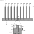
- Figure 1 shows a perspective view of a situation where a fire spreading prevention unit according to the first embodiment is manufactured and an enlarged view of a part B of a thermally conductive member.
- Figure 2 shows a perspective view of a situation after the fire spreading prevention unit shown in Figure 1 is manufactured.
- Figure 3 shows a sectional view taken along line C-C of the fire spreading prevention unit shown in Figure 2 and an enlarged view of a part D.
- the fire spreading prevention unit 1 may be manufactured by inserting the fire spreading prevention sheets 20 into a member before curing of the thermally conductive member 10 and obtaining the thermally conductive member 10 by curing the member before curing.
- Each fire spreading prevention sheet 20 is a multilayer sheet obtained by laminating one or two or more rubber sheets 23, one or two or more heat resistant sheets 21, and one or two or more thermally conductive sheets 22.
- the fire spreading prevention sheet 20 according to this embodiment is a multilayer sheet obtained by laminating one heat resistant sheet 21, one thermally conductive sheet 22, and one rubber sheet 23 in this order.
- the respective numbers of the heat resistant sheets 21, the thermally conductive sheets 22, and the rubber sheets 23 that constitute the fire spreading prevention sheet 20 need only be one or more.
- the heat resistant sheet 21 is a sheet with higher heat resistance than the rubber sheet 23.
- the thermally conductive sheet 22 is a sheet with higher thermal conductivity than the rubber sheet 23 and the heat resistant sheet 21.
- the rubber sheet 23 is a sheet made of a rubber-like elastic body. Terms such as “elastic body” and “cushioning member” may be used in place of the term “rubber-like elastic body”.
- the rubber sheet 23 functions as a protective member that exhibits cushioning characteristics between a plurality of heat sources and prevents the heat resistant sheet 21 from breaking due to a load applied to the heat resistant sheet 21 and also deforms with an expansion of the heat sources.
- the rubber sheet 23 also enables the fire spreading prevention sheet 20 and a heat source that comes into contact with the fire spreading prevention sheet 20 to become readily integrated.
- the rubber sheet 23 may be any of a sponge-like member with internal bubbles and a rubber-like elastic body without any bubbles, the rubber sheet 23 is more preferably a sponge-like member.
- the rubber sheet 23 is constructed to contain: a thermosetting elastomer such as silicone rubber, urethane rubber, isoprene rubber, ethylene-propylene rubber, natural rubber, ethylene-propylene-diene rubber, nitrile rubber (NBR), or styrene-butadiene rubber (SBR); a thermoplastic elastomer that is urethane-based, ester-based, styrene-based, olefin-based, butadiene-based, fluorine-based, or the like; or a combination of these compounds.
- a thermosetting elastomer such as silicone rubber, urethane rubber, isoprene rubber, ethylene-propylene rubber, natural rubber, ethylene-propylene-diene rubber, nitrile rubber (
- the thickness of the rubber sheet 23 is preferably determined by comprehensively considering strength, flexibility, and heat resistance of the sheet.
- the rubber sheet 23 is preferably provided with recesses or grooves on one face or both faces or holes that penetrate the rubber sheet 23 in a thickness direction. This is because air inside the recesses, grooves, or holes exhibits a heat insulation effect.
- one face or both faces of the rubber sheet 23 may be given a mirror finish.
- the thermally conductive sheets 22 each has a protrusion 25 that protrudes beyond the rubber sheets 23 and the heat resistant sheets 21 and that exposes both surfaces in a thickness direction of the thermally conductive sheet 22.
- the fire spreading prevention sheet 20 is inserted into the thermally conductive member 10 with the protrusion 25 facing the thermally conductive member 10 (refer to arrow A in Figure 1 ).
- the fire spreading prevention sheet 20 is erected on the thermally conductive member 10 in a state where the protrusion 25 of the thermally conductive sheet 22 is brought into contact with the thermally conductive member 10.
- the protrusion 25 is a location that exposes the thermally conductive sheet 22 without being covered by the rubber sheet 23 and the heat resistant sheet 21. Therefore, heat transferred from the heat sources to the thermally conductive sheet 22 can be promptly transferred to the thermally conductive member 10.
- the thermally conductive sheet 22 functions as a heat transport passage in the fire spreading prevention sheet 20.
- the thermally conductive sheet 22 may be a sheet made of carbon (such as graphite), Al 2 O 3 , AlN, cBN, or hBN, a resin sheet containing carbon, Al 2 O 3 , AlN, cBN, or hBN as a filler, or a paper sheet containing the filler.
- An example of the resin is aramid fiber.
- the thermally conductive sheet 22 is a sheet containing graphite and/or an aluminum compound.
- the thermally conductive sheet 22 is a graphite sheet or a sheet obtained by dispersing graphite as a filler in resin.
- the thickness of the thermally conductive sheet 22 is not constrained, the thickness preferably ranges from 0.05 to 3 mm and more preferably from 0.08 to 0.6 mm. However, the thickness of the thermally conductive sheet 22 is preferably determined by comprehensively considering strength, flexibility, and heat resistance of the sheet.
- the heat resistant sheet 21 has a function of effectively preventing fire spreading between heat sources.
- the heat resistant sheet 21 is a sheet mainly containing talc.
- the heat resistant sheet 21 may be a sheet containing talc and resin (or paper).
- the resin include aramid fiber.
- a content by percentage of talc in the heat resistant sheet 21 preferably ranges from 55 to 99% by mass and more preferably ranges from 75 to 90% by mass.
- talc is a ceramic with hydrated magnesium silicate as a main component and contains a small amount of impurities such as ferric oxide.
- the heat resistant sheet 21 is a sheet with superior heat resistance and flame retardancy.
- the heat resistant sheet 21 is not limited to a sheet mainly containing talc and need only be constituted of a material with higher heat resistance and higher flame retardancy than at least the rubber sheet 23. Examples of such a material include materials with relatively low thermal conductivity such as silica, mullite, cordierite, steatite, forsterite, titania, and zirconia. More preferably, the heat resistant sheet 21 is a sheet containing talc described above and/or silica described above. Conductivity of the heat resistant sheet 21 is not an issue.
- the heat resistant sheet 21 is preferably a sheet with superior curving properties (or bending properties), and while a thickness of the heat resistant sheet 21 is not constrained, the thickness preferably ranges from 0.05 to 2.0 mm and more preferably from 0.1 to 1.0 mm. Preferably, the thickness of the heat resistant sheet 21 is smaller than that of the rubber sheet 23. However, the thickness of the heat resistant sheet 21 is preferably determined by comprehensively considering strength, flexibility, and heat resistance of the sheet.
- the thermally conductive member 10 is a member disposed between a member (for example, a cooling part) to which heat is to be dissipated from the heat sources and the heat sources.
- a rubber-like elastic body contains a thermally conductive filler 11 with higher thermal conductivity than the rubber-like elastic body (refer to enlarged view of the part B in Figure 1 ).
- the rubber-like elastic body is selected from the same options as the rubber constituting the rubber sheet 23.
- silicone rubber with relatively superior heat resistance is preferable.
- a fire spreading prevention unit 1a according to the second embodiment is provided with fire spreading prevention sheets 20a each disposed to be sandwiched between a plurality of heat sources and the thermally conductive member 10 disposed between a member to which heat from the heat sources is to be transferred and the heat sources.
- the fire spreading prevention sheets 20a are erected on the thermally conductive member 10 at predetermined intervals.
- the fire spreading prevention sheets 20a according to this embodiment each have two heat resistant sheets 21, one thermally conductive sheet 22, and one rubber sheet 23. More specifically, the fire spreading prevention sheets 20a are multilayer sheets each obtained by laminating one heat resistant sheet 21, one thermally conductive sheet 22, one rubber sheet 23, and one heat resistant sheet 21 in this order.
- the heat resistant sheets 21 constitute two outermost layers of the fire spreading prevention sheet 20a.
- the resultant fire spreading prevention sheets 20a are sheets that provide a superior fire spreading prevention effect.
- the protrusion 25 of the thermally conductive sheet 22 protrudes outward beyond the two heat resistant sheets 21 and the one rubber sheet 23.
- the fire spreading prevention sheets 20a are erected on the thermally conductive member 10 by inserting the protrusions 25 into the thermally conductive member 10. Since points other than those described above are in common with the first embodiment, redundant descriptions will be omitted.
- Figure 5 shows a sectional view from a same perspective as the C-C sectional view of the first embodiment and an enlarged view of a part F in the fire spreading prevention unit according to the third embodiment.
- the thermally conductive sheet 22 constitutes one of the outermost layers of the fire spreading prevention sheet 20b. Therefore, the fire spreading prevention sheet 20b can promptly transfer heat from one heat source to the thermally conductive member 10.
- the protrusion 25 of the thermally conductive sheet 22 protrudes outward beyond the two heat resistant sheets 21 and the one rubber sheet 23.
- the fire spreading prevention sheets 20b are erected on the thermally conductive member 10 by inserting the protrusions 25 into the thermally conductive member 10. Since points other than those described above are in common with the respective embodiments described earlier, redundant descriptions will be omitted.
- the plurality of fire spreading prevention sheets 20 are fixed to the thermally conductive film 60 of the tubular bodies 55 by inserting the protrusions 25 into the gaps 65 of the thermally conductive member 50.
- a fixing method of the protrusions 25 and the thermally conductive film 60 is not particularly constrained and examples of the fixing method include adhesion, pressure-sensitive adhesion, and fitting.
- the protrusions 25 may be bent in an L-shape and fixed to front-side surfaces of the tubular bodies 55.
Landscapes
- Chemical & Material Sciences (AREA)
- Chemical Kinetics & Catalysis (AREA)
- Electrochemistry (AREA)
- General Chemical & Material Sciences (AREA)
- Engineering & Computer Science (AREA)
- Manufacturing & Machinery (AREA)
- Secondary Cells (AREA)
- Building Environments (AREA)
Abstract
Description
- Contents described in patents, patent applications, and documents cited in the present application are incorporated by reference into this specification.
- The present invention relates to a fire spreading prevention unit and to a battery provided with the same.
- Currently, with a goal of reducing burdens on the global environment, there is an intensifying worldwide effort to gradually shift from conventional gasoline-powered vehicles and diesel-powered vehicles to electric vehicles. In particular, electric vehicles are becoming popular in European countries such as France, the Netherlands, and Germany as well as in China. The popularization of electric vehicles presents challenges such as development of high-performance batteries and installation of a large number of charging stations.
- Various batteries including the car batteries described above carry a risk of thermal runaway due to an internal short-circuit or the like which may result in ignition, smoke generation, and the like. In recent years, car batteries in which a plurality of battery cells are mounted side by side in an enclosure are known. When ignition, smoke generation, or the like occurs in one battery cell in a battery in which a plurality of battery cells are mounted side by side in this manner, there is a risk that transfer of heat to surrounding battery cells may lead to a greater failure such as ignition, smoke generation, or explosion. Methods of reducing transfer of heat from a battery cell having reached an abnormally high temperature to surrounding battery cells are being studied in order to minimize damage due to such failure. For example, a method of providing a fire spreading prevention member such as a refractory material or a heat insulating layer between the plurality of battery cells is known (refer to Patent Literature 1).
- Patent Literature 1:
Japanese Patent Laid-Open No. 2018-206604 - A temperature of a battery cell rises during charging and discharging. A part of the battery cell may become excessively hot. In such cases, thermal conduction between battery cells must be reduced. In addition, due to the temperature rise of the battery cell, the battery cell and particularly a side surface thereof may possibly expand. Therefore, the fire spreading prevention member between the battery cells is required not to break when a battery cell expands. Furthermore, preferably, not only is the thermal conduction between battery cells reduced but the heat is actively released to the outside to cool the battery cells. This demand applies not only to battery cells but also to other heat sources such as a circuit substrate, an electronic component, and an electronic equipment main body. Moreover, meeting such a demand is also conducive to achieving a sustainable development objective of the present applicant of "securing access by all to sustainable modern energy that is both inexpensive and reliable".
- The present invention has been made in consideration of the problem described above and an object thereof is to provide: a fire spreading prevention unit that prevents fire spreading by reducing thermal conduction between heat sources during a rise in temperature of the heat sources, that is not easily damaged during expansion of the heat sources, and that can actively dissipate heat from the heat sources; and a battery provided with the same.
-
- (1) A fire spreading prevention unit according to an embodiment for achieving the object described above includes: a fire spreading prevention sheet disposed to be sandwiched between a plurality of heat sources; and
- a thermally conductive member disposed between a member to which heat from the heat sources is to be transferred and the heat sources, wherein
- the fire spreading prevention sheet is a multilayer sheet obtained by laminating:
- one or two or more rubber sheets;
- one or two or more heat resistant sheets with higher heat resistance than the rubber sheets; and
- one or two or more thermally conductive sheets with higher thermal conductivity than the rubber sheets and the heat resistant sheets,
- the thermally conductive sheets each have a protrusion that protrudes beyond the rubber sheets and the heat resistant sheets and that exposes both surfaces in a thickness direction of the thermally conductive sheet, and
- (2) In a fire spreading prevention unit according to another embodiment, preferably, the thermally conductive member includes, in a rubber-like elastic body, a thermally conductive filler with higher thermal conductivity than the rubber-like elastic body, and
the protrusion may be inserted into the thermally conductive member from a surface thereof. - (3) In a fire spreading prevention unit according to another embodiment, preferably, the thermally conductive member is provided with a molded body made of rubber or resin as a main material and a thermally conductive film with higher thermal conductivity than the molded body,
- the thermally conductive film is exposed on an outer surface of the molded body, and
- the protrusion may be connected to the thermally conductive film.
- (4) In a fire spreading prevention unit according to another embodiment, preferably, the rubber sheet may be a porous sponge sheet.
- (5) In a fire spreading prevention unit according to another embodiment, preferably, the heat resistant sheet may be a sheet containing talc and/or silica.
- (6) In a fire spreading prevention unit according to another embodiment, preferably, the thermally conductive sheet may be a sheet containing graphite and/or an aluminum compound.
- (7) In a fire spreading prevention unit according to another embodiment, preferably, the multilayer sheet forms a bag having both surfaces in a thickness direction thereof and at least one end surface connecting both surfaces,
- the thermally conductive sheet is disposed inside the bag, and
- the thermally conductive sheet may cause the protrusion to protrude outward by penetrating the bag.
- (8) A battery according to an embodiment for achieving the object described above includes:
- battery cells as a plurality of heat sources inside an enclosure, wherein
- the battery is provided with the fire spreading prevention unit of any one of
claims 1 to 7 inside the enclosure, - the fire spreading prevention sheet is sandwiched between the battery cells, and
- the thermally conductive member is sandwiched between the battery cells and a cooling part of the enclosure.
- The present invention can provide: a fire spreading prevention unit that prevents fire spreading by reducing thermal conduction between heat sources during a rise in temperature of the heat sources, that is not easily damaged during expansion of the heat sources, and that can actively dissipate heat from the heat sources; and a battery provided with the same.
-
- [
Figure 1] Figure 1 shows a perspective view of a situation where a fire spreading prevention unit according to a first embodiment is manufactured and an enlarged view of a part B of a thermally conductive member. - [
Figure 2] Figure 2 shows a perspective view of a situation after the fire spreading prevention unit shown inFigure 1 is manufactured. - [
Figure 3] Figure 3 shows a sectional view taken along line C-C of the fire spreading prevention unit shown inFigure 2 and an enlarged view of a part D. - [
Figure 4] Figure 4 shows a sectional view from a same perspective as the C-C sectional view of the first embodiment and an enlarged view of a part E in a fire spreading prevention unit according to a second embodiment. - [
Figure 5] Figure 5 shows a sectional view from a same perspective as the C-C sectional view of the first embodiment and an enlarged view of a part F in a fire spreading prevention unit according to a third embodiment. - [
Figure 6] Figure 6 shows a sectional view from a same perspective as the C-C sectional view of the first embodiment and an enlarged view of a part G in a fire spreading prevention unit according to a fourth embodiment. - [
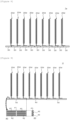
Figure 7] Figure 7 shows a sectional view from a same perspective as the C-C sectional view of the first embodiment in a fire spreading prevention unit according to a fifth embodiment and a fire spreading prevention sheet constituting the fire spreading prevention unit, and a plan view and a right-side view of a thermally conductive member constituting the fire spreading prevention unit. - [
Figure 8] Figure 8 shows a sectional view from a same perspective as the C-C sectional view of the first embodiment in a fire spreading prevention unit according to a sixth embodiment. - [
Figure 9] Figure 9 shows a sectional view from a same perspective as the C-C sectional view of the first embodiment in a fire spreading prevention unit according to a seventh embodiment and a plan view and a right-side view of a thermally conductive member. - [
Figure 10] Figure 10 shows a sectional view of fire spreading prevention sheets according to modifications. - [
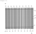
Figure 11] Figure 11 shows a plan view of a thermally conductive member of a fire spreading prevention unit according to an eighth embodiment. - [
Figure 12] Figure 12 shows, by a sectional view from a same perspective as the C-C sectional view of the first embodiment, a situation where the fire spreading prevention unit according to the eighth embodiment is manufactured. - [
Figure 13] Figure 13 shows a longitudinal sectional view of a battery according to the first embodiment. - [
Figure 14] Figure 14 shows a longitudinal sectional view of a battery according to the second embodiment. -
- 1, 1a, 1b, 1c, 1d, 1e, 1f, 1g
- fire spreading prevention unit
- 10, 30, 40, 50
- thermally conductive member
- 11
- thermally conductive filler
- 20, 20a, 20b, 20c, 20d, 20e, 20f
- fire spreading prevention sheet (multilayer sheet)
- 21
- heat resistant sheet
- 22
- thermally conductive sheet
- 23
- rubber sheet (as an example, sponge sheet)
- 25, 25d
- protrusion
- 27
- bag
- 31, 41
- molded body
- 32, 42, 60
- thermally conductive film
- 61
- rubber tube (molded body)
- 70, 70a
- battery
- 71
- enclosure
- 72
- bottom part (member to which heat is to be transferred, cooling part)
- 80
- battery cell (example of heat source)
- Next, respective embodiments of the present invention will be described with reference to the drawings. Note that the respective embodiments described below are not intended to limit the invention as set forth in the accompanying claims and that all of the elements described in the embodiments and combinations thereof are not necessarily essential to solutions proposed by the present invention.
-
Figure 1 shows a perspective view of a situation where a fire spreading prevention unit according to the first embodiment is manufactured and an enlarged view of a part B of a thermally conductive member.Figure 2 shows a perspective view of a situation after the fire spreading prevention unit shown inFigure 1 is manufactured.Figure 3 shows a sectional view taken along line C-C of the fire spreading prevention unit shown inFigure 2 and an enlarged view of a part D. - A fire spreading
prevention unit 1 according to the embodiment is provided with fire spreadingprevention sheets 20 each disposed to be sandwiched between a plurality of heat sources and a thermallyconductive member 10 disposed between a member to which heat from the heat sources is to be transferred and the heat sources. The fire spreadingprevention sheets 20 are erected on the thermallyconductive member 10 at predetermined intervals. Heat sources can be disposed at locations of the predetermined intervals. The fire spreadingprevention unit 1 can be manufactured by making slits in the thermallyconductive member 10 and inserting the fire spreadingprevention sheets 20 into the slits. Alternatively, the fire spreadingprevention unit 1 may be manufactured by inserting the fire spreadingprevention sheets 20 into a member before curing of the thermallyconductive member 10 and obtaining the thermallyconductive member 10 by curing the member before curing. There are nine fire spreadingprevention sheets 20 in this embodiment and subsequent embodiments. As long as there is one or two or more fire spreadingprevention sheets 20, the number thereof can be increased or reduced according to the number of heat sources. While there is one thermallyconductive member 10 in this embodiment, the number of thermallyconductive members 10 is not particularly limited and may be one or two or more. - Each fire spreading
prevention sheet 20 is a multilayer sheet obtained by laminating one or two ormore rubber sheets 23, one or two or more heatresistant sheets 21, and one or two or more thermallyconductive sheets 22. The fire spreadingprevention sheet 20 according to this embodiment is a multilayer sheet obtained by laminating one heatresistant sheet 21, one thermallyconductive sheet 22, and onerubber sheet 23 in this order. The respective numbers of the heatresistant sheets 21, the thermallyconductive sheets 22, and therubber sheets 23 that constitute the fire spreadingprevention sheet 20 need only be one or more. In addition, a method of laminating adjacent sheets is not particularly constrained and a lamination method of interposing connecting means such as an adhesive, a pressure-sensitive adhesive, or a double-sided adhesive tape or a method that does not involve interposing the connecting means (for example, crimping) may be adopted. - The heat
resistant sheet 21 is a sheet with higher heat resistance than therubber sheet 23. The thermallyconductive sheet 22 is a sheet with higher thermal conductivity than therubber sheet 23 and the heatresistant sheet 21. - The
rubber sheet 23 is a sheet made of a rubber-like elastic body. Terms such as "elastic body" and "cushioning member" may be used in place of the term "rubber-like elastic body". Therubber sheet 23 functions as a protective member that exhibits cushioning characteristics between a plurality of heat sources and prevents the heatresistant sheet 21 from breaking due to a load applied to the heatresistant sheet 21 and also deforms with an expansion of the heat sources. In addition, in this embodiment, therubber sheet 23 also enables the fire spreadingprevention sheet 20 and a heat source that comes into contact with the fire spreadingprevention sheet 20 to become readily integrated. - While the
rubber sheet 23 may be any of a sponge-like member with internal bubbles and a rubber-like elastic body without any bubbles, therubber sheet 23 is more preferably a sponge-like member. Preferably, therubber sheet 23 is constructed to contain: a thermosetting elastomer such as silicone rubber, urethane rubber, isoprene rubber, ethylene-propylene rubber, natural rubber, ethylene-propylene-diene rubber, nitrile rubber (NBR), or styrene-butadiene rubber (SBR); a thermoplastic elastomer that is urethane-based, ester-based, styrene-based, olefin-based, butadiene-based, fluorine-based, or the like; or a combination of these compounds. - Preferably, the
rubber sheet 23 is heat resistant to such a degree that therubber sheet 23 does not readily melt, decompose, or the like due to heat transferred from the heat source and can maintain its form. In this embodiment, preferably, therubber sheet 23 is a porous sponge sheet. This is because holes in the sheet contain air that provides a superior heat insulation effect. In addition, preferably, therubber sheet 23 is a sheet that mainly contains silicone rubber. This is because silicone rubber can withstand heat up to around 200°C. In the present application, "mainly" or a "main material" means a ratio exceeding 50% by mass of a whole. More preferably, therubber sheet 23 is a sponge sheet made of silicone rubber. In terms of Shore A hardness, therubber sheet 23 preferably has a hardness of 20 to 80 and more preferably has a hardness of 30 to 70. In order to enhance flame retardancy, therubber sheet 23 may be constructed by dispersing flame-retardant material such as carbon or boric acid in rubber. While a thickness of therubber sheet 23 is not constrained, the thickness preferably ranges from 2 to 20 mm and more preferably from 3 to 8 mm. Preferably, therubber sheet 23 is a thickest layer among the layers constituting the fire spreadingprevention sheet 20. Accordingly, breakage of the heatresistant sheet 21 or the thermallyconductive sheet 22 that constitute the fire spreadingprevention sheet 20 can be reduced. However, the thickness of therubber sheet 23 is preferably determined by comprehensively considering strength, flexibility, and heat resistance of the sheet. When therubber sheet 23 is constructed as a solid rubber sheet, therubber sheet 23 is preferably provided with recesses or grooves on one face or both faces or holes that penetrate therubber sheet 23 in a thickness direction. This is because air inside the recesses, grooves, or holes exhibits a heat insulation effect. In addition, one face or both faces of therubber sheet 23 may be given a mirror finish. - The thermally
conductive sheets 22 each has aprotrusion 25 that protrudes beyond therubber sheets 23 and the heatresistant sheets 21 and that exposes both surfaces in a thickness direction of the thermallyconductive sheet 22. The fire spreadingprevention sheet 20 is inserted into the thermallyconductive member 10 with theprotrusion 25 facing the thermally conductive member 10 (refer to arrow A inFigure 1 ). The fire spreadingprevention sheet 20 is erected on the thermallyconductive member 10 in a state where theprotrusion 25 of the thermallyconductive sheet 22 is brought into contact with the thermallyconductive member 10. Theprotrusion 25 is a location that exposes the thermallyconductive sheet 22 without being covered by therubber sheet 23 and the heatresistant sheet 21. Therefore, heat transferred from the heat sources to the thermallyconductive sheet 22 can be promptly transferred to the thermallyconductive member 10. In other words, the thermallyconductive sheet 22 functions as a heat transport passage in the fire spreadingprevention sheet 20. - The thermally
conductive sheet 22 may be a sheet made of carbon (such as graphite), Al2O3, AlN, cBN, or hBN, a resin sheet containing carbon, Al2O3, AlN, cBN, or hBN as a filler, or a paper sheet containing the filler. An example of the resin is aramid fiber. More preferably, the thermallyconductive sheet 22 is a sheet containing graphite and/or an aluminum compound. In this embodiment, preferably, the thermallyconductive sheet 22 is a graphite sheet or a sheet obtained by dispersing graphite as a filler in resin. While a thickness of the thermallyconductive sheet 22 is not constrained, the thickness preferably ranges from 0.05 to 3 mm and more preferably from 0.08 to 0.6 mm. However, the thickness of the thermallyconductive sheet 22 is preferably determined by comprehensively considering strength, flexibility, and heat resistance of the sheet. - Preferably, the heat
resistant sheet 21 has a function of effectively preventing fire spreading between heat sources. Although any constituent material may be used, preferably, the heatresistant sheet 21 is a sheet mainly containing talc. For example, the heatresistant sheet 21 may be a sheet containing talc and resin (or paper). Examples of the resin include aramid fiber. A content by percentage of talc in the heatresistant sheet 21 preferably ranges from 55 to 99% by mass and more preferably ranges from 75 to 90% by mass. Generally, talc is a ceramic with hydrated magnesium silicate as a main component and contains a small amount of impurities such as ferric oxide. While a type and an amount of the impurities differ depending on where rough talc was produced, the talc contained in the heatresistant sheet 21 is not limited in such aspects. For example, talc subjected to surface treatment by known surface preparation agents such as organic silane-based compounds, organic borane-based compounds, epoxy-based compounds, organic titanate-based compounds, and isocyanate-based compounds may be used. The heatresistant sheet 21 may contain only one type of the talc described above or contain two or more types of talc of which particle sizes, types, surface preparation agents, or the like differ from each other. - Preferably, the heat
resistant sheet 21 is a sheet with superior heat resistance and flame retardancy. The heatresistant sheet 21 is not limited to a sheet mainly containing talc and need only be constituted of a material with higher heat resistance and higher flame retardancy than at least therubber sheet 23. Examples of such a material include materials with relatively low thermal conductivity such as silica, mullite, cordierite, steatite, forsterite, titania, and zirconia. More preferably, the heatresistant sheet 21 is a sheet containing talc described above and/or silica described above. Conductivity of the heatresistant sheet 21 is not an issue. The heatresistant sheet 21 is preferably a sheet with superior curving properties (or bending properties), and while a thickness of the heatresistant sheet 21 is not constrained, the thickness preferably ranges from 0.05 to 2.0 mm and more preferably from 0.1 to 1.0 mm. Preferably, the thickness of the heatresistant sheet 21 is smaller than that of therubber sheet 23. However, the thickness of the heatresistant sheet 21 is preferably determined by comprehensively considering strength, flexibility, and heat resistance of the sheet. - The thermally
conductive member 10 is a member disposed between a member (for example, a cooling part) to which heat is to be dissipated from the heat sources and the heat sources. In this embodiment, in the thermallyconductive member 10, a rubber-like elastic body contains a thermallyconductive filler 11 with higher thermal conductivity than the rubber-like elastic body (refer to enlarged view of the part B inFigure 1 ). Preferably, the rubber-like elastic body is selected from the same options as the rubber constituting therubber sheet 23. As the rubber-like elastic body that constitutes the thermallyconductive member 10, silicone rubber with relatively superior heat resistance is preferable. As the thermallyconductive filler 11, a metal such as Al or Cu can be used in addition to carbon (such as graphite), Al2O3, AlN, cBN, or hBN. A ferromagnetic filler such as iron, cobalt, or nickel may be used as the metal. - The
protrusion 25 of the thermallyconductive sheet 22 is inserted into the thermallyconductive member 10 from a surface thereof. Besides being inserted to a midway position in the thickness direction of the thermallyconductive member 10, theprotrusion 25 may be inserted along an entire length in the thickness direction. In addition, parts of the heatresistant sheet 21 and/or therubber sheet 23 may be inserted into the thermallyconductive member 10 in addition to theprotrusion 25. - Next, a fire spreading prevention unit according to a second embodiment will be described. Redundant descriptions of portions in common with the embodiment described above will be omitted.
-
Figure 4 shows a sectional view from a same perspective as the C-C sectional view of the first embodiment and an enlarged view of a part E in the fire spreading prevention unit according to the second embodiment. - A fire spreading
prevention unit 1a according to the second embodiment is provided with fire spreadingprevention sheets 20a each disposed to be sandwiched between a plurality of heat sources and the thermallyconductive member 10 disposed between a member to which heat from the heat sources is to be transferred and the heat sources. The fire spreadingprevention sheets 20a are erected on the thermallyconductive member 10 at predetermined intervals. The fire spreadingprevention sheets 20a according to this embodiment each have two heatresistant sheets 21, one thermallyconductive sheet 22, and onerubber sheet 23. More specifically, the fire spreadingprevention sheets 20a are multilayer sheets each obtained by laminating one heatresistant sheet 21, one thermallyconductive sheet 22, onerubber sheet 23, and one heatresistant sheet 21 in this order. The heatresistant sheets 21 constitute two outermost layers of the fire spreadingprevention sheet 20a. Therefore, the resultant fire spreadingprevention sheets 20a are sheets that provide a superior fire spreading prevention effect. Theprotrusion 25 of the thermallyconductive sheet 22 protrudes outward beyond the two heatresistant sheets 21 and the onerubber sheet 23. The fire spreadingprevention sheets 20a are erected on the thermallyconductive member 10 by inserting theprotrusions 25 into the thermallyconductive member 10. Since points other than those described above are in common with the first embodiment, redundant descriptions will be omitted. - Next, a fire spreading prevention unit according to a third embodiment will be described. Redundant descriptions of portions in common with the embodiments described above will be omitted.
-
Figure 5 shows a sectional view from a same perspective as the C-C sectional view of the first embodiment and an enlarged view of a part F in the fire spreading prevention unit according to the third embodiment. - A fire spreading
prevention unit 1b according to the third embodiment is provided with fire spreadingprevention sheets 20b each disposed to be sandwiched between a plurality of heat sources and the thermallyconductive member 10 disposed between a member to which heat from the heat sources is to be transferred and the heat sources. The fire spreadingprevention sheets 20b are erected on the thermallyconductive member 10 at predetermined intervals. The fire spreadingprevention sheets 20b according to this embodiment each have two heatresistant sheets 21, one thermallyconductive sheet 22, and onerubber sheet 23. More specifically, the fire spreadingprevention sheets 20b are multilayer sheets each obtained by laminating one thermallyconductive sheet 22, one heatresistant sheet 21, onerubber sheet 23, and one heatresistant sheet 21 in this order. The thermallyconductive sheet 22 constitutes one of the outermost layers of the fire spreadingprevention sheet 20b. Therefore, the fire spreadingprevention sheet 20b can promptly transfer heat from one heat source to the thermallyconductive member 10. Theprotrusion 25 of the thermallyconductive sheet 22 protrudes outward beyond the two heatresistant sheets 21 and the onerubber sheet 23. The fire spreadingprevention sheets 20b are erected on the thermallyconductive member 10 by inserting theprotrusions 25 into the thermallyconductive member 10. Since points other than those described above are in common with the respective embodiments described earlier, redundant descriptions will be omitted. - Next, a fire spreading prevention unit according to a fourth embodiment will be described. Redundant descriptions of portions in common with the embodiments described above will be omitted.
-
Figure 6 shows a sectional view from a same perspective as the C-C sectional view of the first embodiment and an enlarged view of a part G in the fire spreading prevention unit according to the fourth embodiment. - A fire spreading
prevention unit 1c according to the fourth embodiment is provided with fire spreadingprevention sheets 20c each disposed to be sandwiched between a plurality of heat sources and the thermallyconductive member 10 disposed between a member to which heat from the heat sources is to be transferred and the heat sources. The fire spreadingprevention sheets 20c are erected on the thermallyconductive member 10 at predetermined intervals. The fire spreadingprevention sheets 20c according to this embodiment each have two heatresistant sheets 21, two thermallyconductive sheets 22, and onerubber sheet 23. More specifically, the fire spreadingprevention sheets 20c are multilayer sheets each obtained by laminating one thermallyconductive sheet 22, one heatresistant sheet 21, onerubber sheet 23, one heatresistant sheet 21, and one thermallyconductive sheet 22 in this order. The thermallyconductive sheets 22 constitute two outermost layers of each fire spreadingprevention sheet 20c. Therefore, the fire spreadingprevention sheet 20c can more promptly transfer heat from the heat sources sandwiching thesheet 20c to the thermallyconductive member 10. Theprotrusions 25 of the thermallyconductive sheets 22 protrude outward beyond the two heatresistant sheets 21 and the onerubber sheet 23. The fire spreadingprevention sheet 20c is erected on the thermallyconductive member 10 by inserting the twoprotrusions 25 into the thermallyconductive member 10. Since points other than those described above are in common with the respective embodiments described earlier, redundant descriptions will be omitted. - Next, a fire spreading prevention unit according to a fifth embodiment will be described. Redundant descriptions of portions in common with the embodiments described above will be omitted.
-
Figure 7 shows a sectional view from a same perspective as the C-C sectional view of the first embodiment in the fire spreading prevention unit according to the fifth embodiment and a fire spreading prevention sheet constituting the fire spreading prevention unit, and a plan view and a right-side view of a thermally conductive member constituting the fire spreading prevention unit. - A fire spreading
prevention unit 1d according to the fifth embodiment is provided with fire spreadingprevention sheets 20d each disposed to be sandwiched between a plurality of heat sources and a thermallyconductive member 30 disposed between a member to which heat from the heat sources is to be transferred and the heat sources. The fire spreadingprevention sheets 20d are erected on the thermallyconductive member 30 at predetermined intervals. While the fire spreadingprevention sheets 20d according to this embodiment each have a same layer structure as the fire spreadingprevention sheets 20 according to the first embodiment, the fire spreadingprevention sheets 20d differ from the fire spreadingprevention sheets 20 in that aprotrusion 25d of the thermallyconductive sheet 22 is bent in an L-shape in a sectional view. - The thermally
conductive member 30 is not the single thermallyconductive member 10 that constitutes the fire spreadingprevention unit 1 according to the first embodiment but, instead, 10 plate-shaped members.Figure 7 shows a plan view and a right-side view of one of the plate-shaped thermallyconductive members 30. The thermallyconductive member 30 is provided with a moldedbody 31 made of rubber or resin as a main material and a thermallyconductive film 32 with higher thermal conductivity than the moldedbody 31. Preferably, the moldedbody 31 is made of similar options to the rubber of therubber sheet 23. Preferably, the thermallyconductive film 32 is a carbon film with carbon (including graphite) as a main material or a film obtained by dispersing a thermally conductive filler (a filler such as carbon, metal, or ceramics) in a resin. - The thermally
conductive film 32 is exposed on an outer surface of the moldedbody 31. More specifically, the moldedbody 31 has a thin rectangular parallelepiped shape. The thermallyconductive film 32 with a band shape is fixed while proceeding in a length direction (a direction of a longest side) of the moldedbody 31 in a bellows-like pattern and being alternately exposed on a front-side surface and a rear-side surface in a thickness direction of the moldedbody 31. Theprotrusion 25d is fixed to the thermallyconductive member 30 to come into contact with side surfaces and a bottom surface of the thermallyconductive member 30 and to come into contact with the thermallyconductive film 32. A method of fixing theprotrusion 25d and the thermallyconductive member 30 is not particularly constrained and a method of interposing an adhesive, a pressure-sensitive adhesive, or a double-sided adhesive tape or a method such as crimping that does not involve an interposed object may be adopted. - Next, a fire spreading prevention unit according to a sixth embodiment will be described. Redundant descriptions of portions in common with the embodiments described above will be omitted.
-
Figure 8 shows a sectional view from a same perspective as the C-C sectional view of the first embodiment in the fire spreading prevention unit according to the sixth embodiment. - A fire spreading
prevention unit 1e according to the sixth embodiment has a similar configuration to the fire spreadingprevention unit 1d according to the fifth embodiment with the exception of having the fire spreadingprevention sheets 20d of the fifth embodiment being fixed to the thermallyconductive film 32 on the front-side surface of the thermallyconductive member 30. In this manner, theprotrusion 25d may be fixed to the front-side surface of the thermallyconductive member 30. The thermallyconductive member 30 may be a single member with the same structure as that described above. - Next, a fire spreading prevention unit according to a seventh embodiment will be described. Redundant descriptions of portions in common with the embodiments described above will be omitted.
-
Figure 9 shows a sectional view from a same perspective as the C-C sectional view of the first embodiment in the fire spreading prevention unit according to the seventh embodiment and a plan view and a right-side view of a thermally conductive member. - A fire spreading
prevention unit 1f according to the seventh embodiment has a similar configuration to the fire spreadingprevention unit 1e according to the sixth embodiment with the exception of changing the thermallyconductive member 30 of the sixth embodiment to a thermallyconductive member 40. There are a total of 15 thermallyconductive members 40, with three in a direction in which the fire spreadingprevention sheets 20d are lined up and five in a depth direction of a paper plane. However, there are no constraints on the number of the thermallyconductive members 40. -
Figure 9 shows a plan view and a right-side view of one of the thermallyconductive members 40 with a plate shape. The thermallyconductive member 40 is provided with a moldedbody 41 made of rubber or resin as a main material and a thermallyconductive film 42 with higher thermal conductivity than the moldedbody 41. Preferably, the moldedbody 41 is made of similar options to the rubber of therubber sheet 23. Preferably, the thermallyconductive film 42 is a carbon film with carbon (including graphite) as a main material or a film obtained by dispersing a thermally conductive filler (a filler such as carbon, metal, or ceramics) in a resin. - The thermally
conductive film 42 is exposed on an outer surface of the moldedbody 41. More specifically, the moldedbody 41 has a thin rectangular parallelepiped shape. The thermallyconductive film 42 with a band shape is fixed while proceeding in a width direction (a direction of a second-longest side) of the moldedbody 41 in a bellows-like pattern and being alternately exposed on a front-side surface and a rear-side surface in a thickness direction of the moldedbody 41. The thermallyconductive film 42 is fixed in two rows in a length direction (a direction of a longest side) of the moldedbody 41. Theprotrusion 25d is fixed to a front-side surface of the thermallyconductive member 40 to come into contact with the thermallyconductive film 42 of the thermallyconductive member 40. A method of fixing theprotrusion 25d and the thermallyconductive member 40 is not particularly constrained and a method of interposing an adhesive, a pressure-sensitive adhesive, or a double-sided adhesive tape or a method such as crimping that does not involve an interposed object may be adopted. Theprotrusion 25d may be fixed to the rear-side surface of the thermallyconductive member 40. The thermallyconductive member 40 may be a single member with the same structure as that described above. - Next, modifications of a fire spreading prevention sheet that constitutes a fire spreading prevention unit will be described.
-
Figure 10 shows a sectional view of the fire spreading prevention sheets according to the modifications. - A fire spreading
prevention sheet 20e according to a first modification is a multilayer sheet constituted of four layers: the heatresistant sheet 21, the thermallyconductive sheet 22, therubber sheet 23, and the heatresistant sheet 21. The multilayer sheet forms abag 27 having both surfaces in a thickness direction thereof and oneend surface 21a connecting both surfaces. In other words, thebag 27 is formed by the heatresistant sheets 21. The thermallyconductive sheet 21 and therubber sheet 23 are disposed inside thebag 27. The thermallyconductive sheet 21 causes theprotrusion 25 to protrude outward by penetrating thebag 27 from anopening 21b formed in a part of theend surface 21a. - A fire spreading
prevention sheet 20f according to a second modification is a multilayer sheet constituted of five layers: the heatresistant sheet 21, therubber sheet 23, the thermallyconductive sheet 22, therubber sheet 23, and the heatresistant sheet 21. The configuration of the fire spreadingprevention sheet 20f is otherwise similar to that of the fire spreadingprevention sheet 20e according to the first modification. Note that thebag 27 may be formed by therubber sheets 23 instead of the heatresistant sheets 21. In addition, thebag 27 has a form in which only a surface (an upper end surface inFigure 10 ) opposing theend surface 21a is open. However, the upper end surface may be closed. Thebag 27 may have a form in which a periphery thereof is completely closed. - Next, a fire spreading prevention unit according to an eighth embodiment will be described. Redundant descriptions of portions in common with the embodiments described above will be omitted.
-
Figure 11 shows a plan view of a thermally conductive member of the fire spreading prevention unit according to the eighth embodiment.Figure 12 shows, by a sectional view from a same perspective as the C-C sectional view of the first embodiment, a situation where the fire spreading prevention unit according to the eighth embodiment is manufactured. - A thermally
conductive member 50 constituting a fire spreadingprevention unit 1g according to the eighth embodiment is provided with arubber tube 61 that is an example of a molded body made of rubber or resin as a main material and a thermallyconductive film 60 with higher thermal conductivity than therubber tube 61. The thermallyconductive film 60 is exposed on an outer surface of therubber tube 61. Hereinafter, a more specific configuration of the thermallyconductive member 50 will be described. - The thermally
conductive member 50 has a form in which a plurality of elongatedtubular bodies 55 are lined up and coupled to each other. In this embodiment, the thermallyconductive member 50 is provided with 20tubular bodies 55. However, the number oftubular bodies 55 is not limited to 20 and need only be two or more. In this embodiment, strings 56 are adopted as means to couple thetubular bodies 55 to each other. However, coupling means other than thestrings 56 may be used. The thermallyconductive member 50 hasgaps 65 between thetubular bodies 55. Thegaps 65 are spaces necessary for thetubular bodies 55 to collapse when the thermallyconductive member 50 is compressed in the thickness direction. In addition, thegaps 65 can also act as spaces into which theprotrusion 25 of the fire spreadingprevention sheets 20 can be inserted. - The
tubular bodies 55 each have a form in which the thermallyconductive film 60 with a band shape is spirally bound around an outer surface of therubber tube 61 with a cylindrical shape which has a throughpassage 62 in a longitudinal direction. A shape of therubber tube 61 is not limited to a cylindrical shape and may be another shape such as an elliptic cylinder or a rectangular cylinder. The thermallyconductive film 60 and therubber tube 61 may be fixed using any means such as adhesion, welding, and pressure-sensitive adhesion. Preferably, therubber tube 61 can be formed of a selective rubber material similar to that of therubber sheet 23. The thermallyconductive film 60 can be formed of a selective material similar to that of the thermallyconductive film 42 according to the seventh embodiment. - Preferably, the plurality of fire spreading
prevention sheets 20 are fixed to the thermallyconductive film 60 of thetubular bodies 55 by inserting theprotrusions 25 into thegaps 65 of the thermallyconductive member 50. A fixing method of theprotrusions 25 and the thermallyconductive film 60 is not particularly constrained and examples of the fixing method include adhesion, pressure-sensitive adhesion, and fitting. As indicated by a dotted arrow S, theprotrusions 25 may be bent in an L-shape and fixed to front-side surfaces of thetubular bodies 55. Alternatively, as indicated by a dotted arrow T, theprotrusions 25 may penetrate the thickness direction of the thermallyconductive member 50 from thegaps 65, be bent in an L-shape, and be fixed to side surfaces and rear-side surfaces of thetubular bodies 55. - Next, preferred embodiments of a battery according to the present invention will be described.
- First, a battery according to the first embodiment will be described.
-
Figure 13 shows a longitudinal sectional view of the battery according to the first embodiment. - In this case, a "longitudinal sectional view" means a cutaway view of a
battery 70 in a length direction ofbattery cells 80 inside anenclosure 71 of thebattery 70. While thebattery 70 is provided with 10battery cells 80 inFigure 13 , the number ofbattery cells 80 is not particularly limited. - In this embodiment, the
battery 70 is, for example, a car battery. Thebattery 70 has a bottomedenclosure 71 that opens on one side. Preferably, theenclosure 71 is made of aluminum or an aluminum-based alloy. Thebattery 70 is provided with thebattery cells 80 as a plurality of heat sources inside theenclosure 71. Thebattery 70 is provided with the fire spreadingprevention unit 1 according to the first embodiment inside theenclosure 71. The fire spreadingprevention sheets 20 are each sandwiched between thebattery cells 80. The thermallyconductive member 10 is sandwiched between thebattery cells 80 and a bottom part 72 (an example of the cooling part) of theenclosure 71. A type of thebattery 70 is not limited and thebattery 70 is preferably a lithium-ion battery. An electrode is provided to protrude above eachbattery cell 80. Preferably, the plurality ofbattery cells 80 are subjected to forces using a screw or the like inside theenclosure 71 from both sides of theenclosure 71 in a compressing direction so that thebattery cells 80 come into close contact with each other (not illustrated). One or a plurality of water-cooledpipes 73 are provided in thebottom part 72 of theenclosure 71 in order to supply cooling water that is an example of acoolant 75. Thecoolant 75 may be referred to as a cooling medium or a cooling material. - In this manner, the
battery 70 interposes the fire spreadingprevention sheets 20 between thebattery cells 80, interposes the thermallyconductive member 10 between thebattery cells 80 and the bottom part 72 (a member to which heat is to be transferred) of theenclosure 71, and brings theprotrusions 25 of the thermallyconductive sheets 22 of the fire spreadingprevention sheet 20 into contact with the thermallyconductive member 10. Therefore, when one of thebattery cells 80 overheats, heat can be transferred from thebattery cell 80 to thebottom part 72 via the thermallyconductive member 10, thermal conduction from theoverheated battery cell 80 to anadjacent battery cell 80 can be reduced, and conducted heat can be transferred from the thermallyconductive sheets 22 to the thermallyconductive member 10 via theprotrusions 25. Of theprotrusions 25, not only end surfaces but both surfaces in the thickness direction can also be used as thermal conduction locations. As a result, heat transfer from the fire spreadingprevention sheets 20 to the thermallyconductive member 10 can be promoted. - The
battery 70 may be provided with the fire spreadingprevention units prevention sheets prevention sheets - Next, a battery according to the second embodiment will be described. Redundant descriptions of portions of the second embodiment in common with the first embodiment will be omitted.
-
Figure 14 shows a longitudinal sectional view of the battery according to the second embodiment. - In this embodiment, a
battery 70a has the bottomedenclosure 71 that opens on one side. Thebattery 70a is provided with thebattery cells 80 as a plurality of heat sources inside theenclosure 71. Thebattery 70a is provided with the fire spreadingprevention unit 1d according to the fifth embodiment inside theenclosure 71. The fire spreadingprevention sheets 20d are sandwiched between thebattery cells 80. The thermallyconductive member 30 is sandwiched between thebattery cells 80 and the bottom part 72 (an example of the cooling part) of theenclosure 71. A type of thebattery 70a is not limited and thebattery 70a is preferably a lithium-ion battery. - In this manner, the
battery 70a interposes the fire spreadingprevention sheets 20d between thebattery cells 80, interposes the thermallyconductive member 30 between thebattery cells 80 and the bottom part 72 (a member to which heat is to be transferred) of theenclosure 71, and brings theprotrusions 25d of the thermallyconductive sheets 22 of the fire spreadingprevention sheet 20d into contact with the thermallyconductive member 30. Therefore, when one of thebattery cells 80 overheats, heat can be transferred from thebattery cell 80 to thebottom part 72 via the thermallyconductive member 30, thermal conduction from theoverheated battery cell 80 to anadjacent battery cell 80 can be reduced, and conducted heat can be transferred from the thermallyconductive sheets 22 to the thermallyconductive member 30 via theprotrusions 25d. Of theprotrusions 25d, not only end surfaces but at least one surface in the thickness direction can also be used as thermal conduction locations. As a result, heat transfer from the fire spreadingprevention sheets 20d to the thermallyconductive member 30 can be promoted. - The
battery 70a may be provided with the fire spreadingprevention units prevention sheets 20d may be replaced with the fire spreadingprevention sheets - While preferred embodiments of the present invention have been described above, the present invention is not limited to the embodiments and various modifications can be made and implemented.
- In the fire spreading
prevention units rubber sheet 23 may be provided with a large number of depressions that are depressed inward from one surface of therubber sheet 23. The thermallyconductive members like protrusions 25 into contact with the thermallyconductive films protrusions 25d into contact with the thermallyconductive films - The heat sources are not limited to the
battery cells 80 and include all objects that emit heat such as a circuit substrate and an electronic equipment main body. For example, the heat sources may be electronic components such as a capacitor and an IC chip. The fire spreadingprevention units batteries - The plurality of constituent elements of the respective embodiments described above can be freely combined with each other except in cases where they cannot. For example, the
protrusions 20 of the fire spreadingprevention sheets protrusions 25 to be used in the fire spreadingprevention units - The present invention is applicable in fields where preventing fire spreading between heat sources or from a heat source to another location is desirable.
Claims (8)
- A fire spreading prevention unit, comprising:a fire spreading prevention sheet disposed to be sandwiched between a plurality of heat sources; anda thermally conductive member disposed between a member to which heat from the heat sources is to be transferred and the heat sources, whereinthe fire spreading prevention sheet is a multilayer sheet obtained by laminating:one or two or more rubber sheets;one or two or more heat resistant sheets with higher heat resistance than the rubber sheets; andone or two or more thermally conductive sheets with higher thermal conductivity than the rubber sheets and the heat resistant sheets,the thermally conductive sheets each have a protrusion that protrudes beyond the rubber sheets and the heat resistant sheets and that exposes both surfaces in a thickness direction of the thermally conductive sheet, andthe fire spreading prevention sheet is erected on the thermally conductive member in a state where the protrusion of the thermally conductive sheet is brought into contact with the thermally conductive member.
- The fire spreading prevention unit of claim 1, whereinthe thermally conductive member includes, in a rubber-like elastic body, a thermally conductive filler with higher thermal conductivity than the rubber-like elastic body, andthe protrusion is inserted into the thermally conductive member from a surface thereof.
- The fire spreading prevention unit of claim 1, whereinthe thermally conductive member is provided with a molded body made of rubber or resin as a main material and a thermally conductive film with higher thermal conductivity than the molded body,the thermally conductive film is exposed on an outer surface of the molded body, andthe protrusion is connected to the thermally conductive film.
- The fire spreading prevention unit of any one of claims 1 to 3, wherein the rubber sheet is a porous sponge sheet.
- The fire spreading prevention unit of any one of claims 1 to 4, wherein the heat resistant sheet is a sheet containing talc and/or silica.
- The fire spreading prevention unit of any one of claims 1 to 5, wherein the thermally conductive sheet is a sheet containing graphite and/or an aluminum compound.
- The fire spreading prevention unit of any one of claims 1 to 6, whereinthe multilayer sheet forms a bag having both surfaces in a thickness direction thereof and at least one end surface connecting both surfaces,the thermally conductive sheet is disposed inside the bag, andthe thermally conductive sheet causes the protrusion to protrude outward by penetrating the bag.
- A battery, comprising battery cells as a plurality of heat sources inside an enclosure,the battery comprising the fire spreading prevention unit of any one of claims 1 to 7 inside the enclosure, whereinthe fire spreading prevention sheet is sandwiched between the battery cells, andthe thermally conductive member is sandwiched between the battery cells and a cooling part of the enclosure.
Applications Claiming Priority (1)
| Application Number | Priority Date | Filing Date | Title |
|---|---|---|---|
| PCT/JP2021/031461 WO2023026458A1 (en) | 2021-08-27 | 2021-08-27 | Fire spreading prevention unit and battery provided with same |
Publications (2)
| Publication Number | Publication Date |
|---|---|
| EP4395010A1 true EP4395010A1 (en) | 2024-07-03 |
| EP4395010A4 EP4395010A4 (en) | 2025-03-19 |
Family
ID=85322550
Family Applications (1)
| Application Number | Title | Priority Date | Filing Date |
|---|---|---|---|
| EP21955068.8A Pending EP4395010A4 (en) | 2021-08-27 | 2021-08-27 | FIRE SPREAD PREVENTION UNIT AND BATTERY |
Country Status (3)
| Country | Link |
|---|---|
| EP (1) | EP4395010A4 (en) |
| JP (1) | JP7603826B2 (en) |
| WO (1) | WO2023026458A1 (en) |
Families Citing this family (5)
| Publication number | Priority date | Publication date | Assignee | Title |
|---|---|---|---|---|
| JP2025035695A (en) * | 2023-09-04 | 2025-03-14 | イビデン株式会社 | Heat transfer suppression sheet, heat transfer suppression sheet with base, and battery pack |
| JP2025038714A (en) * | 2023-09-07 | 2025-03-19 | イビデン株式会社 | Heat transfer suppression sheet, heat transfer suppression member, and battery pack |
| KR20250139704A (en) * | 2024-03-15 | 2025-09-23 | 주식회사 엘지에너지솔루션 | Battery module, battery pack and vehicle including the same |
| WO2025197214A1 (en) * | 2024-03-19 | 2025-09-25 | 信越ポリマー株式会社 | Cushion member, method for manufacturing same, and battery |
| WO2026034347A1 (en) * | 2024-08-07 | 2026-02-12 | 阿波製紙株式会社 | Inorganic powder sheet and method for manufacturing same |
Family Cites Families (9)
| Publication number | Priority date | Publication date | Assignee | Title |
|---|---|---|---|---|
| JP6234171B2 (en) * | 2013-11-05 | 2017-11-22 | 信越ポリマー株式会社 | Battery module |
| JP6172016B2 (en) * | 2014-03-26 | 2017-08-02 | 株式会社デンソー | Battery module and battery pack |
| JP2018206604A (en) | 2017-06-05 | 2018-12-27 | 積水化学工業株式会社 | Cell, battery module, battery pack, and battery |
| CN118486950A (en) * | 2018-01-25 | 2024-08-13 | 松下知识产权经营株式会社 | Battery pack |
| JP2020140804A (en) * | 2019-02-27 | 2020-09-03 | トヨタ自動車株式会社 | Batteries |
| JP7235562B2 (en) * | 2019-03-29 | 2023-03-08 | イビデン株式会社 | Heat transfer suppression sheet, heat transfer suppression sheet for assembled battery, and assembled battery |
| JP7441643B2 (en) * | 2019-12-23 | 2024-03-01 | 信越ポリマー株式会社 | Cell unit, battery including the same, and battery manufacturing method |
| JP7416613B2 (en) * | 2019-12-23 | 2024-01-17 | 信越ポリマー株式会社 | Multilayer sheet and cell unit equipped with the same |
| CN216413148U (en) * | 2020-02-18 | 2022-04-29 | 罗杰斯公司 | Thermal management multilayer sheet, battery, and battery pack |
-
2021
- 2021-08-27 WO PCT/JP2021/031461 patent/WO2023026458A1/en not_active Ceased
- 2021-08-27 JP JP2023543599A patent/JP7603826B2/en active Active
- 2021-08-27 EP EP21955068.8A patent/EP4395010A4/en active Pending
Also Published As
| Publication number | Publication date |
|---|---|
| WO2023026458A1 (en) | 2023-03-02 |
| JP7603826B2 (en) | 2024-12-20 |
| EP4395010A4 (en) | 2025-03-19 |
| JPWO2023026458A1 (en) | 2023-03-02 |
Similar Documents
| Publication | Publication Date | Title |
|---|---|---|
| EP4395010A1 (en) | Fire spreading prevention unit and battery provided with same | |
| CN109997274B (en) | Wall structure of battery unit, battery submodule, battery module or battery system | |
| CN102187493B (en) | Battery pack | |
| KR101459828B1 (en) | Radiant heat plate for battery cell module and battery cell module having the same | |
| EP3512033B1 (en) | Heat dissipating structure and battery provided with the same | |
| US12266778B2 (en) | Multilayer sheet and cell unit therewith | |
| JP2009301877A (en) | Battery pack device | |
| CN103038933A (en) | Battery module | |
| US11495842B2 (en) | Heat dissipating structure and battery provided with the same | |
| CN102113166A (en) | Battery pack | |
| JP2012014938A (en) | Battery module | |
| KR20190138358A (en) | Battery Module | |
| WO2021106444A1 (en) | Heat conductive member and battery provided with same | |
| JP5131055B2 (en) | Assembled battery device and retaining member for assembled battery device | |
| KR102767949B1 (en) | Heat insulation sheet for battery pack and battery pack comprising the same | |
| KR101976588B1 (en) | Assembly type heat dissipation cartridge and battery pack for electric vehicle using the same | |
| JP5327016B2 (en) | Battery module | |
| CN213638645U (en) | Heat dissipation structure and battery | |
| US20210218099A1 (en) | Battery module with improved stability | |
| KR101966183B1 (en) | Heat dissipation cartridge and battery pack for electric vehicle using the same | |
| JP7402705B2 (en) | Thermal conductive structure and battery equipped with the same | |
| CN116315411A (en) | Spacer and battery cell stack including the spacer | |
| WO2018101695A1 (en) | Wall structure of battery cell, battery sub-module, battery module, or battery system | |
| EP4372871B1 (en) | Battery module comprising cooling plate filled with phase change material | |
| KR101976589B1 (en) | Heat dissipation cartridge and battery pack for electric vehicle using the same |
Legal Events
| Date | Code | Title | Description |
|---|---|---|---|
| STAA | Information on the status of an ep patent application or granted ep patent |
Free format text: STATUS: THE INTERNATIONAL PUBLICATION HAS BEEN MADE |
|
| PUAI | Public reference made under article 153(3) epc to a published international application that has entered the european phase |
Free format text: ORIGINAL CODE: 0009012 |
|
| STAA | Information on the status of an ep patent application or granted ep patent |
Free format text: STATUS: REQUEST FOR EXAMINATION WAS MADE |
|
| 17P | Request for examination filed |
Effective date: 20240308 |
|
| AK | Designated contracting states |
Kind code of ref document: A1 Designated state(s): AL AT BE BG CH CY CZ DE DK EE ES FI FR GB GR HR HU IE IS IT LI LT LU LV MC MK MT NL NO PL PT RO RS SE SI SK SM TR |
|
| DAV | Request for validation of the european patent (deleted) | ||
| DAX | Request for extension of the european patent (deleted) | ||
| A4 | Supplementary search report drawn up and despatched |
Effective date: 20250213 |
|
| RIC1 | Information provided on ipc code assigned before grant |
Ipc: H01M 10/613 20140101ALI20250207BHEP Ipc: H01M 50/204 20210101ALI20250207BHEP Ipc: H01M 10/658 20140101ALI20250207BHEP Ipc: H01M 10/655 20140101ALI20250207BHEP Ipc: H01M 10/647 20140101AFI20250207BHEP |