EP4395008A1 - Battery module, battery and electrical device - Google Patents
Battery module, battery and electrical device Download PDFInfo
- Publication number
- EP4395008A1 EP4395008A1 EP23777758.6A EP23777758A EP4395008A1 EP 4395008 A1 EP4395008 A1 EP 4395008A1 EP 23777758 A EP23777758 A EP 23777758A EP 4395008 A1 EP4395008 A1 EP 4395008A1
- Authority
- EP
- European Patent Office
- Prior art keywords
- battery
- protective film
- heating film
- film
- heating
- Prior art date
- Legal status (The legal status is an assumption and is not a legal conclusion. Google has not performed a legal analysis and makes no representation as to the accuracy of the status listed.)
- Pending
Links
Images


Classifications
-
- H—ELECTRICITY
- H01—ELECTRIC ELEMENTS
- H01M—PROCESSES OR MEANS, e.g. BATTERIES, FOR THE DIRECT CONVERSION OF CHEMICAL ENERGY INTO ELECTRICAL ENERGY
- H01M10/00—Secondary cells; Manufacture thereof
- H01M10/60—Heating or cooling; Temperature control
- H01M10/65—Means for temperature control structurally associated with the cells
- H01M10/657—Means for temperature control structurally associated with the cells by electric or electromagnetic means
- H01M10/6571—Resistive heaters
-
- H—ELECTRICITY
- H01—ELECTRIC ELEMENTS
- H01M—PROCESSES OR MEANS, e.g. BATTERIES, FOR THE DIRECT CONVERSION OF CHEMICAL ENERGY INTO ELECTRICAL ENERGY
- H01M10/00—Secondary cells; Manufacture thereof
- H01M10/60—Heating or cooling; Temperature control
- H01M10/61—Types of temperature control
- H01M10/615—Heating or keeping warm
-
- H—ELECTRICITY
- H01—ELECTRIC ELEMENTS
- H01M—PROCESSES OR MEANS, e.g. BATTERIES, FOR THE DIRECT CONVERSION OF CHEMICAL ENERGY INTO ELECTRICAL ENERGY
- H01M10/00—Secondary cells; Manufacture thereof
- H01M10/60—Heating or cooling; Temperature control
- H01M10/62—Heating or cooling; Temperature control specially adapted for specific applications
- H01M10/625—Vehicles
-
- H—ELECTRICITY
- H01—ELECTRIC ELEMENTS
- H01M—PROCESSES OR MEANS, e.g. BATTERIES, FOR THE DIRECT CONVERSION OF CHEMICAL ENERGY INTO ELECTRICAL ENERGY
- H01M10/00—Secondary cells; Manufacture thereof
- H01M10/60—Heating or cooling; Temperature control
- H01M10/64—Heating or cooling; Temperature control characterised by the shape of the cells
- H01M10/647—Prismatic or flat cells, e.g. pouch cells
-
- H—ELECTRICITY
- H01—ELECTRIC ELEMENTS
- H01M—PROCESSES OR MEANS, e.g. BATTERIES, FOR THE DIRECT CONVERSION OF CHEMICAL ENERGY INTO ELECTRICAL ENERGY
- H01M10/00—Secondary cells; Manufacture thereof
- H01M10/60—Heating or cooling; Temperature control
- H01M10/65—Means for temperature control structurally associated with the cells
- H01M10/658—Means for temperature control structurally associated with the cells by thermal insulation or shielding
-
- H—ELECTRICITY
- H01—ELECTRIC ELEMENTS
- H01M—PROCESSES OR MEANS, e.g. BATTERIES, FOR THE DIRECT CONVERSION OF CHEMICAL ENERGY INTO ELECTRICAL ENERGY
- H01M50/00—Constructional details or processes of manufacture of the non-active parts of electrochemical cells other than fuel cells, e.g. hybrid cells
- H01M50/20—Mountings; Secondary casings or frames; Racks, modules or packs; Suspension devices; Shock absorbers; Transport or carrying devices; Holders
- H01M50/204—Racks, modules or packs for multiple batteries or multiple cells
- H01M50/207—Racks, modules or packs for multiple batteries or multiple cells characterised by their shape
- H01M50/209—Racks, modules or packs for multiple batteries or multiple cells characterised by their shape adapted for prismatic or rectangular cells
-
- H—ELECTRICITY
- H01—ELECTRIC ELEMENTS
- H01M—PROCESSES OR MEANS, e.g. BATTERIES, FOR THE DIRECT CONVERSION OF CHEMICAL ENERGY INTO ELECTRICAL ENERGY
- H01M50/00—Constructional details or processes of manufacture of the non-active parts of electrochemical cells other than fuel cells, e.g. hybrid cells
- H01M50/20—Mountings; Secondary casings or frames; Racks, modules or packs; Suspension devices; Shock absorbers; Transport or carrying devices; Holders
- H01M50/249—Mountings; Secondary casings or frames; Racks, modules or packs; Suspension devices; Shock absorbers; Transport or carrying devices; Holders specially adapted for aircraft or vehicles, e.g. cars or trains
-
- H—ELECTRICITY
- H05—ELECTRIC TECHNIQUES NOT OTHERWISE PROVIDED FOR
- H05B—ELECTRIC HEATING; ELECTRIC LIGHT SOURCES NOT OTHERWISE PROVIDED FOR; CIRCUIT ARRANGEMENTS FOR ELECTRIC LIGHT SOURCES, IN GENERAL
- H05B3/00—Ohmic-resistance heating
- H05B3/20—Heating elements having extended surface area substantially in a two-dimensional [2D] plane, e.g. plate-heater
- H05B3/22—Heating elements having extended surface area substantially in a two-dimensional [2D] plane, e.g. plate-heater non-flexible
- H05B3/28—Heating elements having extended surface area substantially in a two-dimensional [2D] plane, e.g. plate-heater non-flexible heating conductor embedded in insulating material
-
- H—ELECTRICITY
- H05—ELECTRIC TECHNIQUES NOT OTHERWISE PROVIDED FOR
- H05B—ELECTRIC HEATING; ELECTRIC LIGHT SOURCES NOT OTHERWISE PROVIDED FOR; CIRCUIT ARRANGEMENTS FOR ELECTRIC LIGHT SOURCES, IN GENERAL
- H05B3/00—Ohmic-resistance heating
- H05B3/20—Heating elements having extended surface area substantially in a two-dimensional [2D] plane, e.g. plate-heater
- H05B3/34—Heating elements having extended surface area substantially in a two-dimensional [2D] plane, e.g. plate-heater flexible, e.g. heating nets or webs
-
- H—ELECTRICITY
- H05—ELECTRIC TECHNIQUES NOT OTHERWISE PROVIDED FOR
- H05B—ELECTRIC HEATING; ELECTRIC LIGHT SOURCES NOT OTHERWISE PROVIDED FOR; CIRCUIT ARRANGEMENTS FOR ELECTRIC LIGHT SOURCES, IN GENERAL
- H05B3/00—Ohmic-resistance heating
- H05B3/20—Heating elements having extended surface area substantially in a two-dimensional [2D] plane, e.g. plate-heater
- H05B3/34—Heating elements having extended surface area substantially in a two-dimensional [2D] plane, e.g. plate-heater flexible, e.g. heating nets or webs
- H05B3/36—Heating elements having extended surface area substantially in a two-dimensional [2D] plane, e.g. plate-heater flexible, e.g. heating nets or webs heating conductor embedded in insulating material
-
- B—PERFORMING OPERATIONS; TRANSPORTING
- B60—VEHICLES IN GENERAL
- B60L—PROPULSION OF ELECTRICALLY-PROPELLED VEHICLES; SUPPLYING ELECTRIC POWER FOR AUXILIARY EQUIPMENT OF ELECTRICALLY-PROPELLED VEHICLES; ELECTRODYNAMIC BRAKE SYSTEMS FOR VEHICLES IN GENERAL; MAGNETIC SUSPENSION OR LEVITATION FOR VEHICLES; MONITORING OPERATING VARIABLES OF ELECTRICALLY-PROPELLED VEHICLES; ELECTRIC SAFETY DEVICES FOR ELECTRICALLY-PROPELLED VEHICLES
- B60L50/00—Electric propulsion with power supplied within the vehicle
- B60L50/50—Electric propulsion with power supplied within the vehicle using propulsion power supplied by batteries or fuel cells
- B60L50/60—Electric propulsion with power supplied within the vehicle using propulsion power supplied by batteries or fuel cells using power supplied by batteries
-
- H—ELECTRICITY
- H01—ELECTRIC ELEMENTS
- H01M—PROCESSES OR MEANS, e.g. BATTERIES, FOR THE DIRECT CONVERSION OF CHEMICAL ENERGY INTO ELECTRICAL ENERGY
- H01M2220/00—Batteries for particular applications
- H01M2220/20—Batteries in motive systems, e.g. vehicle, ship, plane
-
- Y—GENERAL TAGGING OF NEW TECHNOLOGICAL DEVELOPMENTS; GENERAL TAGGING OF CROSS-SECTIONAL TECHNOLOGIES SPANNING OVER SEVERAL SECTIONS OF THE IPC; TECHNICAL SUBJECTS COVERED BY FORMER USPC CROSS-REFERENCE ART COLLECTIONS [XRACs] AND DIGESTS
- Y02—TECHNOLOGIES OR APPLICATIONS FOR MITIGATION OR ADAPTATION AGAINST CLIMATE CHANGE
- Y02E—REDUCTION OF GREENHOUSE GAS [GHG] EMISSIONS, RELATED TO ENERGY GENERATION, TRANSMISSION OR DISTRIBUTION
- Y02E60/00—Enabling technologies; Technologies with a potential or indirect contribution to GHG emissions mitigation
- Y02E60/10—Energy storage using batteries
Definitions
- embodiments of the present application provide a battery module, a battery and a power consuming device, in which a heating film inside the battery can be physically protected to prevent metal wire in the heating film from being damaged or broken, thereby improving the overall safety and reliability of the heating film and in turn improving the safety performance of the battery.
- the protective film is attached to the side of the heating film away from the battery cells, that is, the protective film can physically protect the heating film without affecting the normal heating function of the heating film on the battery cells.
- the protective film extends in an extension direction of the heating film, that is, extends in the first direction, so that the protective film covers the first surface of the heating film and can fully protect the heating film, thereby further improving the protective effect of the protective film on the heating film.
- the one-piece protective film is also conducive to increasing the strength of the protective film itself.
- the battery cell includes two first walls spaced apart from each other and arranged oppositely in a second direction
- the battery module includes two heating films respectively attached to the two first walls and two protective films respectively attached to the two heating films, the first direction being perpendicular to the second direction.
- providing the heating films on both sides of the battery cell can improve the heating effect on the battery cell.
- Providing the protective films on both sides can physically protect the heating films on both sides, thereby improving the overall safety performance of the battery.
- the battery module further includes end plates arranged at two ends of the plurality of battery cells in the first direction, end portions of the heating film and the protective film in the first direction being fixedly connected to the end plates.
- the heating film is provided on the first walls of the battery cells, and the protective film is provided on the first surface of the heating film. Allowing the heating film and the protective film to be fixedly connected to the end plates of the battery module can avoid failure of the heating film and the protective film due to sliding from their original positions during transportation, etc. The fixed connection of the heating film and the protective film with the end plates of the battery module can ensure their normal operation.
- the end portions of the protective film in the first direction are provided with holes, and the protective film is fixedly connected to the end plates through the holes.
- the protective film is fixedly connected to the end plates to achieve protection of the protective film on the heating film.
- the end portions of the protective film in the first direction are provided with the holes, and the protective film is fixedly connected to the end plates through the holes.
- the heating film and the protective film are fixedly connected to the end plates, so as to maintain their functions in the battery module.
- the bonding of the first surface of the protective film to the heating film can further improve the fixing between the protective film and the heating film, so as to avoid failure of the fixed connection between the protective film and the end plates to cause the protective film to no longer protect the heating film.
- the protective film has a thickness of 100 ⁇ m to 200 ⁇ m.
- the protective film is configured to physically protect metal wire in the heating film. Therefore, the protective film is preferably made of an insulating, non-metallic material. The protective film made of a non-metallic material can better protect the heating film than those made of other materials.
- using the protective film made of polyethylene terephthalate or high polymer of polypropylene can minimize the cost.
- the heating film 66 may be arranged on one side or both sides of the battery cells 6. If both sides of the battery cells 6 are provided with the heating films 66, the heating films 66 have better heating effect on the battery cells 6.
- FIG. 6 is a schematic diagram of a structure of a protective film according to an embodiment of the present application. As shown in FIG. 6 , the end portions of the protective film 68 in the first direction are provided with holes 681, and the protective film 68 is fixedly connected to the end plates 67 through the holes 681.
Landscapes
- Chemical & Material Sciences (AREA)
- Chemical Kinetics & Catalysis (AREA)
- Electrochemistry (AREA)
- General Chemical & Material Sciences (AREA)
- Engineering & Computer Science (AREA)
- Manufacturing & Machinery (AREA)
- Physics & Mathematics (AREA)
- Electromagnetism (AREA)
- Aviation & Aerospace Engineering (AREA)
- Battery Mounting, Suspending (AREA)
Abstract
Description
- The patent application claims priority to
Chinese Patent Application No. 202220746628.6, entitled "BATTERY MODULE, BATTERY, AND POWER CONSUMING DEVICE", filed on April 1, 2022 - The present application relates to the technical field of batteries, and in particular to a battery module, a battery, and a power consuming device.
- With the increasing environmental pollution, more and more attention has been focused on new energy industry. In the new energy industry, battery technology is an important factor for development.
- In the development of battery technology, the safety performance of batteries is also a noticeable issue. How to improve the safety performance of batteries is an urgent technical problem to be solved in the battery technology.
- In view of the above problem, embodiments of the present application provide a battery module, a battery and a power consuming device, in which a heating film inside the battery can be physically protected to prevent metal wire in the heating film from being damaged or broken, thereby improving the overall safety and reliability of the heating film and in turn improving the safety performance of the battery.
- In a first aspect, a battery module is provided. The battery module includes: a plurality of battery cells arranged in a first direction; a heating film extending in the first direction and attached to a first wall of each of the plurality of battery cells, the first wall being parallel to the first direction, the heating film being configured to heat the plurality of battery cells; and a protective film extending in the first direction and attached to a first surface of the heating film away from the battery cell, the protective film being configured to protect the heating film.
- In the embodiments of the present application, the battery module includes the plurality of battery cells arranged in the first direction and the heating film configured to heat the battery cells. The heating film is attached to the first walls of the plurality of battery cells, that is, the heating film also extends in the first direction. The battery module further includes the protective film configured to protect the heating film. Providing the protective film and allowing the protective film to be attached to the first surface of the heating film away from the battery cells can not only ensure the heating function of the heating film on the battery cells, but also physically protect the heating film to prevent metal wire in the heating film from being damaged or broken by external collisions, thereby improving the overall safety and reliability of the heating film and in turn improving the safety performance of the battery.
- In a possible implementation, the protective film covers the first surface of the heating film.
- In the embodiments of the present application, the protective film is attached to the side of the heating film away from the battery cells, that is, the protective film can physically protect the heating film without affecting the normal heating function of the heating film on the battery cells. The protective film extends in an extension direction of the heating film, that is, extends in the first direction, so that the protective film covers the first surface of the heating film and can fully protect the heating film, thereby further improving the protective effect of the protective film on the heating film. In addition, the one-piece protective film is also conducive to increasing the strength of the protective film itself.
- In a possible implementation, the battery cell includes two first walls spaced apart from each other and arranged oppositely in a second direction, and the battery module includes two heating films respectively attached to the two first walls and two protective films respectively attached to the two heating films, the first direction being perpendicular to the second direction.
- In the embodiments of the present application, providing the heating films on both sides of the battery cell can improve the heating effect on the battery cell. Providing the protective films on both sides can physically protect the heating films on both sides, thereby improving the overall safety performance of the battery.
- In a possible implementation, the battery module further includes end plates arranged at two ends of the plurality of battery cells in the first direction, end portions of the heating film and the protective film in the first direction being fixedly connected to the end plates.
- In the embodiments of the present application, the heating film is provided on the first walls of the battery cells, and the protective film is provided on the first surface of the heating film. Allowing the heating film and the protective film to be fixedly connected to the end plates of the battery module can avoid failure of the heating film and the protective film due to sliding from their original positions during transportation, etc. The fixed connection of the heating film and the protective film with the end plates of the battery module can ensure their normal operation.
- In a possible implementation, the end portions of the protective film in the first direction are provided with holes, and the protective film is fixedly connected to the end plates through the holes.
- In the embodiments of the present application, the protective film is fixedly connected to the end plates to achieve protection of the protective film on the heating film. The end portions of the protective film in the first direction are provided with the holes, and the protective film is fixedly connected to the end plates through the holes. This fixing method is simple to implement and highly operable, and is conducive to wide application in production.
- In a possible implementation, the heating film is bonded to the first surface of the protective film.
- In the embodiments of the present application, the heating film and the protective film are fixedly connected to the end plates, so as to maintain their functions in the battery module. The bonding of the first surface of the protective film to the heating film can further improve the fixing between the protective film and the heating film, so as to avoid failure of the fixed connection between the protective film and the end plates to cause the protective film to no longer protect the heating film.
- In a possible implementation, the protective film has a thickness of 100 µm to 200 µm.
- In the embodiments of the present application, the protective film that is too thin may fail to play a proper protective role, and the protective film that is too thick will increase the production cost. Allowing the thickness of the protective film to be between 100 µm and 200 µm can not only ensure the protective effect of the protective film itself, but also reduce the cost, which is conducive to mass production.
- In a possible implementation, the protective film is made of a non-metallic material.
- In the embodiments of the present application, the protective film is configured to physically protect metal wire in the heating film. Therefore, the protective film is preferably made of an insulating, non-metallic material. The protective film made of a non-metallic material can better protect the heating film than those made of other materials.
- In a possible implementation, the protective film is made of a high polymer material.
- In the embodiments of the present application, owing to the low cost of high polymer materials, the protective film made of a high polymer material can not only have a good protective effect, but also have a lower cost than those made of other non-metallic materials, which is conducive to wide application in actual production.
- In a possible implementation, the protective film is made of polyethylene terephthalate or high polymer of polypropylene.
- In the embodiments of the present application, using the protective film made of polyethylene terephthalate or high polymer of polypropylene can minimize the cost.
- In a possible implementation, the protective film is made of a transparent material.
- In the embodiments of the present application, the heating film is attached to the first walls of the plurality of battery cells to heat the plurality of battery cells, and the protective film is attached to the first surface of the heating film to physically protect the metal wire in the heating film so as to prevent the metal wire from being broken, etc. The protective film is made of the transparent material so that, during the operation, an operator can observe through the protective film whether there are wrinkles or other abnormalities in the heating film.
- In a second aspect, a battery is provided. The battery includes: a case; and a battery module in the foregoing embodiments, the battery module being accommodated in the case.
- In a third aspect, a power consuming device is provided. The power consuming device includes a battery in the foregoing embodiments, the battery being configured to supply electric energy.
- To more clearly illustrate the technical solutions of the embodiments of the present application, the accompanying drawings required in the embodiments of the present application will be briefly described below. It will be apparent that the accompanying drawings described below are merely some of the embodiments of the present application, and for those of ordinary skill in the art, other drawings can be obtained based on these accompanying drawings without any inventive efforts.
-
FIG. 1 is a schematic diagram of a structure of a vehicle according to an embodiment of the present application; -
FIG. 2 is a schematic exploded view of a structure of a battery according to an embodiment of the present application; -
FIG. 3 is a schematic exploded view of a structure of a battery cell according to an embodiment of the present application; -
FIG. 4 is a schematic diagram of a structure of a battery module according to an embodiment of the present application; -
FIG. 5 is a schematic diagram of a structure of a battery module according to another embodiment of the present application; and -
FIG. 6 is a schematic diagram of a structure of a protective film according to an embodiment of the present application. -
-
vehicle 1,battery 2,battery module 3,battery cell 6; -
controller 11,motor 12, case 20,electrode assembly 61,shell 62,electrode terminal 63, connectingmember 64,pressure relief mechanism 65,heating film 66,end plate 67,protective film 68; -
first case portion 201, second case portion 202,accommodating space 203,housing 621,end cap 622,positive electrode terminal 631,negative electrode terminal 632, connectingwire harness 661, reserved slit 662,hole 681. - The embodiments of the technical solutions of the present application will be described below in detail with reference to the accompanying drawings. The following embodiments are merely intended to more clearly illustrate the technical solutions of the present application, and therefore merely serve as examples but are not intended to limit the scope of protection of the present application.
- Unless otherwise defined, all technical and scientific terms used herein have the same meanings as those commonly understood by those skilled in the art to which the present application belongs. The terms used herein are merely for the purpose of describing specific embodiments, but are not intended to limit the present application. The terms "including" and "having" and any variations thereof in the specification and the claims of the present application and in the brief description of the accompanying drawings described above are intended to cover non-exclusive inclusion.
- In the description of the embodiments of the present application, the technical terms "first", "second", etc. are merely used for distinguishing different objects, and are not to be construed as indicating or implying relative importance or implicitly indicating the number, particular order or primary-secondary relationship of the indicated technical features. In the description of the embodiments of the present application, the phrase "multiple" means two or more, unless otherwise explicitly and specifically defined.
- The phrase "embodiment" herein means that the specific features, structures or characteristics described with reference to the embodiment can be encompassed in at least one embodiment of the present application. The phrase at various locations in the specification does not necessarily refer to the same embodiment, or an independent or alternative embodiment exclusive of another embodiment. Those skilled in the art should understand explicitly or implicitly that the embodiment herein can be combined with other embodiments.
- In the description of the embodiments of the present application, the term "and/or" is merely intended to describe the associated relationship of associated objects, representing that three relationships may exist. For example, A and/or B may be expressed as: only A exists, both A and B exist, and only B exists. In addition, the character "/" herein generally indicates an "or" relationship between the associated objects.
- In the description of the embodiments of the present application, the term "multiple" means two or more (including two), similarly the term "multiple groups" means two or more groups (including two groups), and the term "multiple pieces" means two or more pieces (including two pieces).
- In the description of the embodiments of the present application, the orientations or positional relationships indicated by the technical terms "central", "longitudinal", "transverse", "length", "width", "thickness", "upper", "lower", "front", "rear", "left", "right", "vertical", "horizontal", "top", "bottom", "inner", "outer", "clockwise", "counterclockwise", "axial", "radial", "circumferential", etc. are based on the orientations or positional relationships shown in the accompanying drawings, are merely intended to facilitate and simplify the description of the embodiments of the present application, rather than indicating or implying that the apparatus or element referred to must have a particular orientation or be constructed and operated in a particular orientation, and therefore cannot be construed as limiting the embodiments of the present application.
- In the description of the embodiments of the present application, unless otherwise explicitly specified and defined, the technical terms such as "mounting", "connecting", "connection" and "fixing" should be understood in a broad sense. For example, they may be a fixed connection, a detachable connection, or an integrated connection; may be a mechanical connection or an electric connection; and may be a direct connection or an indirect connection by means of an intermediate medium, or may be communication between interiors of two elements or interaction between the two elements. For those of ordinary skill in the art, the specific meanings of the above terms in the embodiments of the present application can be understood according to specific situations.
- In the present application, the battery cell may be a lithium metal secondary battery, a sodium metal battery, a magnesium metal battery, etc., which will not be limited in the embodiments of the present application. The battery cell may be cylindrical, flat or have other shapes, which will not be limited in the embodiments of the present application. The battery cells are generally classified into three types depending on the way of package: cylindrical battery cells, prismatic battery cells and pouch battery cells, which will also not be limited in the embodiments of the present application. For ease of description, a lithium metal battery is taken as an example for description in the following embodiments.
- A battery mentioned in the embodiments of the present application refers to a single physical module including one or more battery cells to provide a higher voltage and capacity. For example, the battery mentioned in the present application may include a battery module, a battery pack, etc. The battery generally includes a case for packaging one or more battery cells. The case can prevent liquid or other foreign matters from affecting charging or discharging of the battery cell(s).
- With its gradual maturity, new energy technology is applied in more and more industries. In a new energy vehicle, a battery case is installed in the vehicle as an energy source. The battery in the battery case discharges to drive operation of an electric motor of the new energy vehicle. However, an existing battery case may be affected by the ambient temperature when in use. Taking a lithium-ion battery as an example, the battery has an extremely poor discharge capacity at a low temperature, and even if the battery is fully charged, the driving capacity of the vehicle will be greatly reduced. In addition, low-temperature charging greatly affects the service life of the traction battery, because at a low temperature, charged ions inside the battery have poor conductivity, and the transfer and embedding capabilities of the charges inside the structure of a negative material are also poor. If the battery is charged with normal current at a low temperature, a large number of lithium ions accumulate on, but cannot be embedded in, the surface of the negative electrode, and electrons will be deposited on the surface of the electrode to form pure lithium accumulation. However, metal lithium is very prone to uneven crystal growth, and when dendrites grow to a sufficient size, they may pierce a separator, resulting in direct connection between the positive electrode and the negative electrode, causing internal short circuit in the battery.
- In order to solve the problem that the operation is affected when the battery case is interfered by the external temperature, it has been proposed to add, in the battery module in the battery case, a heating film that can heat the battery cells. The heating film is fixed to a side of the battery cell by means of bonding, and can generate heat when energized and transfer the heat to the battery cells so as to increase the operating temperature of the battery cells. However, at present, a heating layer of the heating film is generally made of copper wire. During the assembly process of the battery, the heating layer in the heating film is easy to be damaged or even broken. An energizing circuit in the heating film is a high-voltage circuit. When the copper wire is broken, two ends of the broken wire may be loaded with high voltage that will cause sparking and failure of the copper wire or the electrode, eventually resulting in fire and failure of the heating film or even the entire battery to cause serious safety accidents.
- In order to solve the problem described above, the embodiments of the present application provide a technical solution, in which a heating film inside a battery is physically protected by means of a protective film so as to prevent metal wire in the heating film from being damaged or broken, thereby improving the overall safety and reliability of the heating film and in turn improving the safety performance of the battery.
- The protective film described in the embodiments of the present application is suitable for use in a battery module, a battery, and a power consuming device using a battery.
- The power consuming device may be a vehicle, a mobile phone, a portable device, a notebook computer, a ship, a spacecraft, an electric toy, an electric tool, etc. The vehicle may be a fuel vehicle, a gas vehicle or a new-energy vehicle. The new-energy vehicle may be a battery electric vehicle, a hybrid vehicle, an extended-range vehicle, etc. The spacecraft includes an airplane, a rocket, an aerospace plane, a spaceship, etc. The electric toy includes a stationary or mobile electric toy, such as a game machine, an electric toy car, an electric toy ship, and an electric toy airplane. The electric tool includes a metal cutting electric tool, a grinding electric tool, an assembly power tool, and a railway power tool such as an electric drill, an electric grinder, an electric wrench, an electric screwdriver, an electric hammer, an electric impact drill, a concrete vibrator and an electric planer. The power consuming devices mentioned above are not specifically limited in the embodiments of the present application.
- For ease of description, an example in which the power consuming device is a vehicle is taken for description in the following embodiments.
-
FIG. 1 is a schematic diagram of a structure of avehicle 1 according to an embodiment of the present application. As shown inFIG. 1 , abattery 2 is provided inside thevehicle 1, and thebattery 2 may be arranged at the bottom, the head or the rear of thevehicle 1. Thebattery 2 can be used to supply power to thevehicle 1. For example, thebattery 2 may serve as an operating power supply for thevehicle 1. - The
vehicle 1 may further include acontroller 11 and amotor 12. Thecontroller 11 is used to control thebattery 2 to supply power to themotor 12 to meet, for example, the operating power demand during starting, navigation and traveling of thevehicle 1. - In some embodiments of the present application, the
battery 2 can not only serve as an operation power supply for thevehicle 1, but also serve as a driving power supply for thevehicle 1, in place of or partially in place of fuel or natural gas, to supply driving power to thevehicle 1. -
FIG. 2 is a schematic exploded view of thebattery 2 according to an embodiment of the present application. As shown inFIG. 2 , thebattery 2 includes a case 20, abattery module 3, aheating film 66 and a protective film 68 (theprotective film 68 covers the heating film 66). Thebattery module 3 includesmultiple battery cells 6. Thebattery module 3, theheating film 66 and theprotective film 68 are accommodated in the case 20. - The case 20 is configured to accommodate the
battery cells 6. The case 20 may be of various structures. In some embodiments, the case 20 may include afirst case portion 201 and a second case portion 202, thefirst case portion 201 and the second case portion 202 fit together in a covering manner, and thefirst case portion 201 and the second case portion 202 jointly define anaccommodating space 203 for accommodating thebattery cells 6. The second case portion 202 may be of a hollow structure with one end open, thefirst case portion 201 is of a plate-like structure, and thefirst case portion 201 fits with the open side of the second case portion 202 in a covering manner to form the case 20 having theaccommodating space 203. Thefirst case portion 201 and the second case portion 202 may each also be of a hollow structure with one side open, and the open side of thefirst case portion 201 fits with the open side of the second case portion 202 in a covering manner to form the case 20 having theaccommodating space 203. Of course, thefirst case portion 201 and the second case portion 202 may be in various shapes such as a cylinder and a cuboid. - To improve the sealing performance after the
first case portion 201 is connected to the second case portion 202, a sealing member such as sealant or a sealing ring may be provided between thefirst case portion 201 and the second case portion 202. - Assuming that the
first case portion 201 fits with the top of the second case portion 202 in a covering manner, thefirst case portion 201 may be referred to as an upper case cover, and the second case portion 202 may be referred to as a lower case body. - In the
battery 2,multiple battery cells 6 are provided. Themultiple battery cells 6 may be in series connection, in parallel connection or in series-parallel connection. The series-parallel connection means that some of themultiple battery cells 6 are in series connection and some are in parallel connection. Themultiple battery cells 6 may be directly combined together in series connection, in parallel connection or in series-parallel connection, and then a unit composed of themultiple battery cells 6 is accommodated in the case 20. Of course, it is also possible thatmultiple battery cells 6 are in series connection, in parallel connection or in series-parallel connection to form a battery module (not shown), and then multiple battery modules are in series connection, in parallel connection or in series-parallel connection to form a unit and are accommodated in the case 20. Themultiple battery cells 6 in the battery module may be electrically connected to each other by means of a busbar component so as to achieve the series connection, parallel connection or series-parallel connection between themultiple battery cells 6 in the battery module. -
FIG. 3 is a schematic diagram of a structure of abattery cell 6 according to an embodiment of the present application. Thebattery cell 6 includes one ormore electrode assemblies 61, ahousing 621, and anend cap 622. Thehousing 621 and theend cap 622 form a shell or abattery box 62. Walls of thehousing 621 and theend cap 622 are both referred to as walls of thebattery cell 6. For acuboid battery cell 6, the walls of thehousing 621 include a bottom wall and four side walls. Thehousing 621 may be shaped depending on the shape of a combination of the one ormore electrode assemblies 61. For example, thehousing 621 may be a hollow cuboid, cube or cylinder, and one of faces of thehousing 621 is provided with an opening through which the one ormore electrode assemblies 61 can be placed into thehousing 621. For example, when thehousing 621 is a hollow cuboid or cube, one of flat faces of thehousing 621 is an open face, that is, this flat face has no wall body so as to achieve communication between the inside and the outside of thehousing 621. When thehousing 621 is a hollow cylinder, an end face of thehousing 621 is an open face, that is, this end face has no wall body so as to achieve communication between the inside and the outside of thehousing 621. Theend cap 622 covers the opening and is connected to thehousing 621 to form an enclosed chamber for placing theelectrode assembly 61. Thehousing 621 is filled with an electrolyte, such as an electrolytic solution. - The
battery cell 6 may further include twoelectrode terminals 63. The twoelectrode terminals 63 may be arranged on theend cap 622. Theend cap 622 is generally in the shape of a flat plate, the twoelectrode terminals 63 are fixed to a flat-plate face of theend cap 622, and the twoelectrode terminals 63 are respectively apositive electrode terminal 631 and anegative electrode terminal 632. Eachelectrode terminal 63 is correspondingly provided with a connecting member 64 (or referred to as a current collecting member 64) that is located between theend cap 622 and theelectrode assembly 61 to achieve electrical connection between theelectrode assembly 61 and theelectrode terminal 63. - In the
battery cell 6, according to the requirements in actual application, one ormore battery assemblies 61 may be provided. As shown inFIG. 6 , fourindependent battery assemblies 61 are provided in thebattery cell 6. - The
battery cell 6 may be further provided with apressure relief mechanism 65. Thepressure relief mechanism 65 is configured to be actuated, when the internal pressure or temperature of thebattery cell 6 reaches a threshold, to relieve the internal pressure or temperature. - The
pressure relief mechanism 65 may be of various possible pressure relief structures, which is not limited in the embodiments of the present application. For example, thepressure relief mechanism 65 may be a temperature-sensitive pressure relief mechanism that is configured to melt when the internal temperature of thebattery cell 6 provided with thepressure relief mechanism 65 reaches a threshold; and/or thepressure relief mechanism 65 may be a pressure-sensitive pressure relief mechanism that is configured to fracture when the internal pressure of thebattery cell 6 provided with thepressure relief mechanism 65 reaches a threshold. -
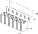
FIG. 4 is a schematic diagram of a structure of a battery module according to an embodiment of the present application. As shown inFIG. 4 , thebattery module 3 includes:multiple battery cells 6, themultiple battery cells 6 being arranged in a first direction; aheating film 66 extending in the first direction and attached to a first wall of eachbattery cell 6 of themultiple battery cells 6, the first wall being parallel to the first direction, theheating film 66 being configured to heat themultiple battery cells 6; and aprotective film 68, theprotective film 68 extending in the first direction and attached to a first surface of theheating film 66 away from thebattery cells 6, theprotective film 68 being configured to protect theheating film 66. - As mentioned above, in order to prevent the battery from being affected by external environments such as low temperature, the
heating film 66 is attached to the first walls of thebattery cells 6 in thebattery module 3. In order to protect theheating film 66, theprotective film 68 is attached to the first surface of theheating film 66 away from thebattery cells 6 in the first direction. - In the foregoing solution, the
battery module 3 includes themultiple battery cells 6 arranged in the first direction and theheating film 66 configured to heat thebattery cells 6. Theheating film 66 is attached to the first walls of themultiple battery cells 6, that is, theheating film 66 also extends in the first direction. Thebattery module 3 further includes theprotective film 68, and theprotective film 68 is configured to protect theheating film 66. Providing theprotective film 68 and allowing theprotective film 68 to be attached to the first surface of theheating film 66 away from thebattery cells 6 can not only ensure the heating function of theheating film 66 on thebattery cells 6, but also physically protect theheating film 66 to prevent metal wire in theheating film 66 from being damaged or broken by external collisions, thereby improving the overall safety and reliability of theheating film 66 and in turn improving the safety performance of thebattery 2. - Optionally, the
protective film 68 covers the first surface of theheating film 66. - The
protective film 68 covers theheating film 66, and theprotective film 68 can only protect the covered region of theheating film 66. Theprotective film 68 cannot protect the region of theheating film 66 that is not covered by theprotective film 68. - In the foregoing solution, the
protective film 68 is attached to the side of theheating film 66 away from thebattery cells 6, that is, theprotective film 68 can physically protect theheating film 66 without affecting the normal heating function of theheating film 66 on thebattery cells 6. Theprotective film 68 extends in an extension direction of theheating film 66, that is, extends in the first direction, so that theprotective film 68 completely covers the first surface of theheating film 66 and can fully protect theheating film 66, thereby further improving the protective effect of theprotective film 68 on theheating film 66. In addition, the one-pieceprotective film 68 is also conducive to increasing the strength of theprotective film 68 itself. -
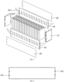
FIG. 5 is a schematic diagram of a structure of a battery module according to another embodiment of the present application. As shown inFIG. 5 , thebattery cell 6 includes two first walls spaced apart from each other and arranged oppositely in a second direction, and thebattery module 3 includes twoheating films 66 respectively attached to the two first walls and twoprotective films 68 respectively attached to the twoheating films 66, the first direction being perpendicular to the second direction. - The
heating film 66 may be arranged on one side or both sides of thebattery cells 6. If both sides of thebattery cells 6 are provided with theheating films 66, theheating films 66 have better heating effect on thebattery cells 6. - In the foregoing solution, providing the
heating films 66 on both sides of thebattery cells 6 can improve the heating effect on thebattery cells 6; and accordingly, providing theprotective films 68 on both sides can physically protect theheating films 66 on both sides, thereby improving the overall safety performance of the battery. - Optionally, the
battery module 3 further includesend plates 67. Theend plates 67 are arranged at two ends of themultiple battery cells 6 in the first direction, and end portions of theheating film 66 and theprotective film 68 in the first direction are fixedly connected to theend plates 67. - As shown in
FIG. 5 , a connectingwire harness 661 is provided on theheating film 66. The twoheating films 66 on thebattery cells 6 in the second direction are connected in series by means of the connectingwire harness 661 to jointly heat thebattery cells 6. The positions of theheating film 66 and theprotective film 68 in thebattery cells 6 cannot be changed, in order to maintain their actions on thebattery cells 6. - In the foregoing solution, the
heating film 66 is arranged on the first walls of thebattery cells 6, and theprotective film 68 is arranged on the first surface of theheating film 66. Allowing theheating film 66 and theprotective film 68 to be fixedly connected to theend plates 67 of thebattery module 3 can fix the positions of theheating film 66 and theprotective film 68 so as to avoid failure of theheating film 66 and theprotective film 68 due to theheating film 66 and theprotective film 68 sliding from their original positions during transportation, etc. The fixed connection of theheating film 66 and theprotective film 68 with theend plates 67 of thebattery module 3 can ensure their normal operation. -
FIG. 6 is a schematic diagram of a structure of a protective film according to an embodiment of the present application. As shown inFIG. 6 , the end portions of theprotective film 68 in the first direction are provided withholes 681, and theprotective film 68 is fixedly connected to theend plates 67 through theholes 681. - The
protective film 68 is connected to theend plates 67 in various manners, as long as they are fixedly connected to each other, which is not limited in the present application. However, during the actual production process, choosing a convenient and highly operable connecting method is conducive to widespread promotion in practical applications. - In the foregoing solution, the
protective film 68 is fixedly connected to theend plates 67 to achieve continuous protection of theprotective film 68 on theheating film 66. The fixing method in which the end portions of theprotective film 68 in the first direction are provided with theholes 681 so that theprotective film 681 is fixedly connected to theend plates 67 through theholes 681 is simple to implement, is highly operable, and is conducive to wide application in production. - Optionally, the
heating film 66 is bonded to the first surface of theprotective film 68. - The
heating film 66 and theprotective film 68 are fixedly connected to theend plates 67, so as to maintain their functions in thebattery module 3. If the method of fixing theheating film 66 and theprotective film 68 to theend plates 67 is destroyed, the heating film and the protective film cannot be in action on thebattery cells 6 in thebattery module 3. - Bonding the
heating film 66 to thebattery cells 6 and bonding theheating film 66 to the first surface of theprotective film 68 can further improve the fixing of theheating film 66 and theprotective film 68 in thebattery module 3, so as to avoid failure of the fixed connection between theprotective film 68 and theend plates 67 to cause theprotective film 68 to no longer protect theheating film 66. In addition, bonding theprotective film 68 to theheating film 66 before theprotective film 68 is fixedly connected to theend plates 67 can prevent separation of theprotective film 68 and theheating film 66 during transportation. - Optionally, the
protective film 68 has a thickness of 100 µm to 200 µm. - The thickness of the
protective film 68 has certain effect on its performance. If theprotective film 68 is too thin, theprotective film 68 may fail to play a proper protective role; and theprotective film 68 that is too thick will increase the production cost. - In the foregoing solution, allowing the thickness of the
protective film 68 to be between 100 µm and 200 µm can not only ensure the protective effect of theprotective film 68 itself, but also reduce the cost, which is conducive to mass production. - Optionally, the
protective film 68 is made of a non-metallic material. - The non-metallic materials usually refer to glass, ceramics, graphite and rock which are mainly composed of inorganic substances, and wood, plastics and rubber which are main composed of organic substances, and are composed of crystalline or amorphous substances. In the embodiments of the present application, the metal wire in the
heating film 66 is made of metal. Therefore, theprotective film 68 in the present application may be made of glass, wood, plastics, rubber or other materials, that is, made of an insulating material. - In the foregoing solution, the
protective film 68 is configured to physically protect the metal wire in theheating film 66. Therefore, theprotective film 68 is preferably made of an insulating non-metallic material. Theprotective film 68 made of a non-metallic material can better protect theheating film 66 than those made of other materials. - Optionally, the
protective film 68 is made of a high polymer material. - As shown in
FIG. 5 , reservedslits 662 are provided in theheating film 66. When thebattery cells 6 are heated by theheating film 66, thebattery cells 6 expand after being heated. In order to prevent irreversible deformation of theheating film 66 due to the expansion of thebattery cells 6, thereserved slits 662 are provided in theheating film 66 to improve the deformation capability of theheating film 66. - In the embodiments of the present application, the
protective film 68 may be made of a high polymer material, such as rubber, fiber and plastics, having good deformation capability so as to prevent theprotective film 68 from being damaged due to its inadaptation to the deformation when theheating film 66 deforms. - In the foregoing solution, the
protective film 68 made of a high polymer material can not only have good deformation capability and protective capability, but also have a lower cost than those made of other non-metallic materials, which is conducive to wide application in actual production. - Optionally, the
protective film 68 is made of polyethylene terephthalate or high polymer of polypropylene. - In the foregoing solution, using the
protective film 68 made of polyethylene terephthalate or high polymer of polypropylene can minimize the cost. - Optionally, the
protective film 68 is made of a transparent material. - When the
battery cells 6 is heated by theheating film 66, the heating effect on thebattery cells 6 may be reduced if the surface of theheating film 66 is wrinkled, etc. - In the foregoing solution, the
heating film 66 is attached to the first walls of themultiple battery cells 6 to heat themultiple battery cells 6; and theprotective film 68 is attached to the first surface of theheating film 66 to physically protect the metal wire in theheating film 66 so as to prevent the metal wire from being broken. Theprotective film 68 is made of the transparent material, so that during the operation, an operator can observe through theprotective film 68 whether there are wrinkles or other abnormalities in theheating film 66. - An embodiment of the present application further provides a
battery 2, including: a case 20; and abattery module 3 according to the foregoing embodiments, thebattery module 3 being accommodated in the case 20. - An embodiment of the present application further provides a power consuming device, including a
battery 2 according to the foregoing embodiments, thebattery 2 being configured to supply electric energy. - Although the present application has been described with reference to the preferred embodiments, various modifications can be made, and equivalents can be provided to substitute for the components thereof without departing from the scope of the present application. In particular, the technical features mentioned in the embodiments can be combined in any manner, provided that there is no structural conflict. The present application is not limited to the specific embodiments disclosed herein, but includes all the technical solutions that fall within the scope of the claims.
Claims (13)
- A battery module (3), comprising:a plurality of battery cells (6), the plurality of battery cells (6) being arranged in a first direction;a heating film (66) extending in the first direction and attached to a first wall of each battery cell (6) of the plurality of battery cells (6), the first wall being parallel to the first direction, the heating film (66) being configured to heat the plurality of battery cells (6); anda protective film (68), the protective film (68) extending in the first direction and attached to a first surface of the heating film (66) away from the battery cell (6), the protective film (68) being configured to protect the heating film (66).
- The battery module (3) according to claim 1, wherein the protective film (68) covers the first surface of the heating film (66).
- The battery module (3) according to claim 1, wherein the battery cell (6) comprises two first walls spaced apart from each other and arranged oppositely in a second direction, and the battery module (3) comprises two heating films (66) respectively attached to the two first walls and two protective films (68) respectively attached to the two heating films (66), the first direction being perpendicular to the second direction.
- The battery module (3) according to claim 1, the battery module (3) further comprising:
end plates (67) arranged at two ends of the plurality of battery cells (6) in the first direction, end portions of the heating film (66) and the protective film (68) in the first direction being fixedly connected to the end plates (67). - The battery module (3) according to claim 4, wherein the end portions of the protective film 68 in the first direction are provided with holes (681), and the protective film (68) is fixedly connected to the end plates (67) through the holes (681).
- The battery module (3) according to any one of claims 1 to 5, wherein the protective film (68) is bonded to the first surface of the heating film (66).
- The battery module (3) according to any one of claims 1 to 5, wherein the protective film (68) has a thickness of 100 µm to 200 µm.
- The battery module (3) according to any one of claims 1 to 5, wherein the protective film (68) is made of a non-metallic material.
- The battery module (3) according to any one of claims 1 to 5, wherein the protective film (68) is made of a high polymer material.
- The battery module (3) according to claim 9, wherein the protective film (68) is made of polyethylene terephthalate or high polymer of polypropylene.
- The battery module (3) according to any one of claims 1 to 5, wherein the protective film (68) is made of a transparent material.
- A battery (2), comprising:a case (20); anda battery module (3) of any one of claims 1 to 11, the battery module (3) being accommodated in the case (20).
- A power consuming device, comprising a battery (2) of claim 12, the battery (2) being configured to supply electric energy.
Applications Claiming Priority (2)
| Application Number | Priority Date | Filing Date | Title |
|---|---|---|---|
| CN202220746628.6U CN217182275U (en) | 2022-04-01 | 2022-04-01 | Battery modules, batteries, electrical equipment |
| PCT/CN2023/079727 WO2023185380A1 (en) | 2022-04-01 | 2023-03-06 | Battery module, battery and electrical device |
Publications (2)
| Publication Number | Publication Date |
|---|---|
| EP4395008A1 true EP4395008A1 (en) | 2024-07-03 |
| EP4395008A4 EP4395008A4 (en) | 2025-03-26 |
Family
ID=82745903
Family Applications (1)
| Application Number | Title | Priority Date | Filing Date |
|---|---|---|---|
| EP23777758.6A Pending EP4395008A4 (en) | 2022-04-01 | 2023-03-06 | Battery module, battery and electrical device |
Country Status (5)
| Country | Link |
|---|---|
| US (1) | US20240313299A1 (en) |
| EP (1) | EP4395008A4 (en) |
| CN (1) | CN217182275U (en) |
| DE (1) | DE202023003149U1 (en) |
| WO (1) | WO2023185380A1 (en) |
Families Citing this family (3)
| Publication number | Priority date | Publication date | Assignee | Title |
|---|---|---|---|---|
| CN217182275U (en) * | 2022-04-01 | 2022-08-12 | 宁德时代新能源科技股份有限公司 | Battery modules, batteries, electrical equipment |
| CN115189074B (en) * | 2022-09-09 | 2022-12-09 | 深圳海润新能源科技有限公司 | Battery module and battery pack |
| CN222927643U (en) * | 2024-06-20 | 2025-05-30 | 宁德时代新能源科技股份有限公司 | Battery and electricity utilization device |
Family Cites Families (6)
| Publication number | Priority date | Publication date | Assignee | Title |
|---|---|---|---|---|
| JP2006334331A (en) * | 2005-05-30 | 2006-12-14 | Noboru Oyamada | Sheet type heat generator |
| JP3224790U (en) * | 2019-08-30 | 2020-01-23 | ピュアエナジー株式会社 | Storage battery and storage battery system |
| CN212874605U (en) * | 2020-09-11 | 2021-04-02 | 湖北亿纬动力有限公司 | Battery heating film structure and battery module |
| CN113571809A (en) * | 2021-07-15 | 2021-10-29 | 北京海博思创科技股份有限公司 | Battery packs and vehicles |
| CN216872109U (en) * | 2022-02-10 | 2022-07-01 | 宁德时代新能源科技股份有限公司 | A heating assembly, battery and electric device |
| CN217182275U (en) * | 2022-04-01 | 2022-08-12 | 宁德时代新能源科技股份有限公司 | Battery modules, batteries, electrical equipment |
-
2022
- 2022-04-01 CN CN202220746628.6U patent/CN217182275U/en active Active
-
2023
- 2023-03-06 DE DE202023003149.4U patent/DE202023003149U1/en active Active
- 2023-03-06 WO PCT/CN2023/079727 patent/WO2023185380A1/en not_active Ceased
- 2023-03-06 EP EP23777758.6A patent/EP4395008A4/en active Pending
-
2024
- 2024-05-23 US US18/672,019 patent/US20240313299A1/en active Pending
Also Published As
| Publication number | Publication date |
|---|---|
| CN217182275U (en) | 2022-08-12 |
| US20240313299A1 (en) | 2024-09-19 |
| EP4395008A4 (en) | 2025-03-26 |
| DE202023003149U1 (en) | 2026-04-30 |
| WO2023185380A1 (en) | 2023-10-05 |
Similar Documents
| Publication | Publication Date | Title |
|---|---|---|
| US11764437B2 (en) | Battery, power consumption apparatus, and method and apparatus for producing battery | |
| US11699829B2 (en) | Box of battery, battery, power consumpiion apparatus, method for producing battery and apparatus for producing battery | |
| EP4395008A1 (en) | Battery module, battery and electrical device | |
| EP4092818A1 (en) | Battery box body, battery, electric device, method and apparatus for preparing box body | |
| EP4485655B1 (en) | Battery and electric device | |
| CN218414802U (en) | Battery cells, batteries and electrical devices | |
| US12519183B2 (en) | Battery cell, battery, and electrical device | |
| EP4675730A1 (en) | Battery, electric device and energy storage device | |
| CN218919088U (en) | End cover assembly of battery unit, battery and electricity utilization device | |
| US20250385382A1 (en) | Battery, electrical device, and energy storage device | |
| US20220311084A1 (en) | Battery, power consumption apparatus, method and apparatus for producing battery | |
| CN217740616U (en) | Single cells, batteries and electrical devices | |
| WO2023143286A1 (en) | Battery cell, battery, and electric device | |
| EP4181281A1 (en) | Battery, electric device, and method and device for preparing battery | |
| US20250379344A1 (en) | Battery and electrical apparatus | |
| EP4376147A1 (en) | Battery, electric device, and method and device for preparing battery | |
| US12125613B2 (en) | Cable, battery and electricity consuming device | |
| CN116569394A (en) | Battery cell, battery, electric device, method and device for manufacturing battery cell | |
| EP4297144A1 (en) | Electrode assembly and battery cell related to same, and battery, apparatus and manufacturing method | |
| CN223638545U (en) | Battery cells, battery devices, electrical devices, and energy storage devices | |
| US20240243424A1 (en) | Battery, power consumption apparatus, method and apparatus for preparing battery | |
| CN223941799U (en) | Battery monomer, battery device and electric equipment | |
| US20250096400A1 (en) | Battery cell, battery, electrical device and method for wrapping around battery cell with insulating film | |
| EP4478479A1 (en) | Battery cell, battery, and electrical device | |
| EP4435944A1 (en) | Battery protection structure, battery, electric device, and method and apparatus for manufacturing battery |
Legal Events
| Date | Code | Title | Description |
|---|---|---|---|
| STAA | Information on the status of an ep patent application or granted ep patent |
Free format text: STATUS: THE INTERNATIONAL PUBLICATION HAS BEEN MADE |
|
| PUAI | Public reference made under article 153(3) epc to a published international application that has entered the european phase |
Free format text: ORIGINAL CODE: 0009012 |
|
| STAA | Information on the status of an ep patent application or granted ep patent |
Free format text: STATUS: REQUEST FOR EXAMINATION WAS MADE |
|
| 17P | Request for examination filed |
Effective date: 20240326 |
|
| AK | Designated contracting states |
Kind code of ref document: A1 Designated state(s): AL AT BE BG CH CY CZ DE DK EE ES FI FR GB GR HR HU IE IS IT LI LT LU LV MC ME MK MT NL NO PL PT RO RS SE SI SK SM TR |
|
| RAP1 | Party data changed (applicant data changed or rights of an application transferred) |
Owner name: CONTEMPORARY AMPEREX TECHNOLOGY(HONG KONG) LIMITED |
|
| A4 | Supplementary search report drawn up and despatched |
Effective date: 20250224 |
|
| RIC1 | Information provided on ipc code assigned before grant |
Ipc: H01M 10/625 20140101ALI20250218BHEP Ipc: H01M 10/6571 20140101ALI20250218BHEP Ipc: H01M 10/615 20140101AFI20250218BHEP |
|
| DAV | Request for validation of the european patent (deleted) | ||
| DAX | Request for extension of the european patent (deleted) | ||
| STAA | Information on the status of an ep patent application or granted ep patent |
Free format text: STATUS: EXAMINATION IS IN PROGRESS |
|
| 17Q | First examination report despatched |
Effective date: 20260122 |