EP4092818A1 - Battery box body, battery, electric device, method and apparatus for preparing box body - Google Patents
Battery box body, battery, electric device, method and apparatus for preparing box body Download PDFInfo
- Publication number
- EP4092818A1 EP4092818A1 EP21742028.0A EP21742028A EP4092818A1 EP 4092818 A1 EP4092818 A1 EP 4092818A1 EP 21742028 A EP21742028 A EP 21742028A EP 4092818 A1 EP4092818 A1 EP 4092818A1
- Authority
- EP
- European Patent Office
- Prior art keywords
- pressure relief
- battery
- collection chamber
- thermal management
- management component
- Prior art date
- Legal status (The legal status is an assumption and is not a legal conclusion. Google has not performed a legal analysis and makes no representation as to the accuracy of the status listed.)
- Granted
Links
- 238000000034 method Methods 0.000 title abstract description 11
- 230000007246 mechanism Effects 0.000 claims abstract description 139
- 239000012530 fluid Substances 0.000 claims abstract description 36
- 230000001681 protective effect Effects 0.000 claims description 71
- 239000000463 material Substances 0.000 claims description 58
- 238000002844 melting Methods 0.000 claims description 29
- 230000008018 melting Effects 0.000 claims description 29
- 238000007373 indentation Methods 0.000 claims description 13
- 230000007423 decrease Effects 0.000 claims description 3
- 238000004519 manufacturing process Methods 0.000 claims description 3
- 238000010586 diagram Methods 0.000 description 15
- 239000007789 gas Substances 0.000 description 11
- 230000000712 assembly Effects 0.000 description 7
- 238000000429 assembly Methods 0.000 description 7
- 238000009434 installation Methods 0.000 description 7
- 238000001816 cooling Methods 0.000 description 6
- 230000002708 enhancing effect Effects 0.000 description 6
- 238000004891 communication Methods 0.000 description 5
- 238000011161 development Methods 0.000 description 5
- 238000005516 engineering process Methods 0.000 description 5
- 239000007788 liquid Substances 0.000 description 5
- 239000007773 negative electrode material Substances 0.000 description 5
- 239000007774 positive electrode material Substances 0.000 description 5
- 238000003466 welding Methods 0.000 description 5
- 230000008859 change Effects 0.000 description 4
- 230000000694 effects Effects 0.000 description 4
- 239000008151 electrolyte solution Substances 0.000 description 4
- 239000000243 solution Substances 0.000 description 4
- LYCAIKOWRPUZTN-UHFFFAOYSA-N Ethylene glycol Chemical compound OCCO LYCAIKOWRPUZTN-UHFFFAOYSA-N 0.000 description 3
- HBBGRARXTFLTSG-UHFFFAOYSA-N Lithium ion Chemical compound [Li+] HBBGRARXTFLTSG-UHFFFAOYSA-N 0.000 description 3
- 239000004743 Polypropylene Substances 0.000 description 3
- 229910001128 Sn alloy Inorganic materials 0.000 description 3
- 239000000956 alloy Substances 0.000 description 3
- 239000002826 coolant Substances 0.000 description 3
- 238000013461 design Methods 0.000 description 3
- 229910001416 lithium ion Inorganic materials 0.000 description 3
- XLYOFNOQVPJJNP-UHFFFAOYSA-N water Chemical compound O XLYOFNOQVPJJNP-UHFFFAOYSA-N 0.000 description 3
- 230000009471 action Effects 0.000 description 2
- 239000000853 adhesive Substances 0.000 description 2
- 230000001070 adhesive effect Effects 0.000 description 2
- 229910052782 aluminium Inorganic materials 0.000 description 2
- XAGFODPZIPBFFR-UHFFFAOYSA-N aluminium Chemical compound [Al] XAGFODPZIPBFFR-UHFFFAOYSA-N 0.000 description 2
- 239000012809 cooling fluid Substances 0.000 description 2
- 230000001066 destructive effect Effects 0.000 description 2
- 238000007599 discharging Methods 0.000 description 2
- 238000004134 energy conservation Methods 0.000 description 2
- 229920006351 engineering plastic Polymers 0.000 description 2
- 238000004880 explosion Methods 0.000 description 2
- 238000010438 heat treatment Methods 0.000 description 2
- 230000006872 improvement Effects 0.000 description 2
- VNWKTOKETHGBQD-UHFFFAOYSA-N methane Chemical compound C VNWKTOKETHGBQD-UHFFFAOYSA-N 0.000 description 2
- -1 polypropylene Polymers 0.000 description 2
- 229920001155 polypropylene Polymers 0.000 description 2
- 229910001415 sodium ion Inorganic materials 0.000 description 2
- 239000000126 substance Substances 0.000 description 2
- OKTJSMMVPCPJKN-UHFFFAOYSA-N Carbon Chemical compound [C] OKTJSMMVPCPJKN-UHFFFAOYSA-N 0.000 description 1
- RYGMFSIKBFXOCR-UHFFFAOYSA-N Copper Chemical compound [Cu] RYGMFSIKBFXOCR-UHFFFAOYSA-N 0.000 description 1
- 235000015842 Hesperis Nutrition 0.000 description 1
- 235000012633 Iberis amara Nutrition 0.000 description 1
- DGAQECJNVWCQMB-PUAWFVPOSA-M Ilexoside XXIX Chemical compound C[C@@H]1CC[C@@]2(CC[C@@]3(C(=CC[C@H]4[C@]3(CC[C@@H]5[C@@]4(CC[C@@H](C5(C)C)OS(=O)(=O)[O-])C)C)[C@@H]2[C@]1(C)O)C)C(=O)O[C@H]6[C@@H]([C@H]([C@@H]([C@H](O6)CO)O)O)O.[Na+] DGAQECJNVWCQMB-PUAWFVPOSA-M 0.000 description 1
- WHXSMMKQMYFTQS-UHFFFAOYSA-N Lithium Chemical compound [Li] WHXSMMKQMYFTQS-UHFFFAOYSA-N 0.000 description 1
- JLVVSXFLKOJNIY-UHFFFAOYSA-N Magnesium ion Chemical compound [Mg+2] JLVVSXFLKOJNIY-UHFFFAOYSA-N 0.000 description 1
- FKNQFGJONOIPTF-UHFFFAOYSA-N Sodium cation Chemical compound [Na+] FKNQFGJONOIPTF-UHFFFAOYSA-N 0.000 description 1
- IDSMHEZTLOUMLM-UHFFFAOYSA-N [Li].[O].[Co] Chemical class [Li].[O].[Co] IDSMHEZTLOUMLM-UHFFFAOYSA-N 0.000 description 1
- JDZCKJOXGCMJGS-UHFFFAOYSA-N [Li].[S] Chemical compound [Li].[S] JDZCKJOXGCMJGS-UHFFFAOYSA-N 0.000 description 1
- 238000009825 accumulation Methods 0.000 description 1
- 239000003570 air Substances 0.000 description 1
- 230000009286 beneficial effect Effects 0.000 description 1
- 229910052799 carbon Inorganic materials 0.000 description 1
- 239000000112 cooling gas Substances 0.000 description 1
- 239000000110 cooling liquid Substances 0.000 description 1
- 229910052802 copper Inorganic materials 0.000 description 1
- 239000010949 copper Substances 0.000 description 1
- 238000005336 cracking Methods 0.000 description 1
- 238000009792 diffusion process Methods 0.000 description 1
- QHGJSLXSVXVKHZ-UHFFFAOYSA-N dilithium;dioxido(dioxo)manganese Chemical compound [Li+].[Li+].[O-][Mn]([O-])(=O)=O QHGJSLXSVXVKHZ-UHFFFAOYSA-N 0.000 description 1
- 239000000428 dust Substances 0.000 description 1
- 239000003792 electrolyte Substances 0.000 description 1
- 230000007613 environmental effect Effects 0.000 description 1
- 239000012634 fragment Substances 0.000 description 1
- 239000002737 fuel gas Substances 0.000 description 1
- 239000003292 glue Substances 0.000 description 1
- 238000002955 isolation Methods 0.000 description 1
- 229910052744 lithium Inorganic materials 0.000 description 1
- 229910000625 lithium cobalt oxide Inorganic materials 0.000 description 1
- GELKBWJHTRAYNV-UHFFFAOYSA-K lithium iron phosphate Chemical compound [Li+].[Fe+2].[O-]P([O-])([O-])=O GELKBWJHTRAYNV-UHFFFAOYSA-K 0.000 description 1
- 229910001425 magnesium ion Inorganic materials 0.000 description 1
- 229910052751 metal Inorganic materials 0.000 description 1
- 239000002184 metal Substances 0.000 description 1
- 229910021645 metal ion Inorganic materials 0.000 description 1
- 239000000203 mixture Substances 0.000 description 1
- 239000003345 natural gas Substances 0.000 description 1
- 238000004806 packaging method and process Methods 0.000 description 1
- 230000000149 penetrating effect Effects 0.000 description 1
- 230000008569 process Effects 0.000 description 1
- 238000012545 processing Methods 0.000 description 1
- 230000009467 reduction Effects 0.000 description 1
- 238000007789 sealing Methods 0.000 description 1
- 238000000926 separation method Methods 0.000 description 1
- 229910052710 silicon Inorganic materials 0.000 description 1
- 239000010703 silicon Substances 0.000 description 1
- 239000011734 sodium Substances 0.000 description 1
- 239000007921 spray Substances 0.000 description 1
- 239000002699 waste material Substances 0.000 description 1
- 238000004804 winding Methods 0.000 description 1
Images


Classifications
-
- H—ELECTRICITY
- H01—ELECTRIC ELEMENTS
- H01M—PROCESSES OR MEANS, e.g. BATTERIES, FOR THE DIRECT CONVERSION OF CHEMICAL ENERGY INTO ELECTRICAL ENERGY
- H01M50/00—Constructional details or processes of manufacture of the non-active parts of electrochemical cells other than fuel cells, e.g. hybrid cells
- H01M50/60—Arrangements or processes for filling or topping-up with liquids; Arrangements or processes for draining liquids from casings
- H01M50/609—Arrangements or processes for filling with liquid, e.g. electrolytes
- H01M50/618—Pressure control
-
- H—ELECTRICITY
- H01—ELECTRIC ELEMENTS
- H01M—PROCESSES OR MEANS, e.g. BATTERIES, FOR THE DIRECT CONVERSION OF CHEMICAL ENERGY INTO ELECTRICAL ENERGY
- H01M50/00—Constructional details or processes of manufacture of the non-active parts of electrochemical cells other than fuel cells, e.g. hybrid cells
- H01M50/30—Arrangements for facilitating escape of gases
- H01M50/342—Non-re-sealable arrangements
- H01M50/3425—Non-re-sealable arrangements in the form of rupturable membranes or weakened parts, e.g. pierced with the aid of a sharp member
-
- H—ELECTRICITY
- H01—ELECTRIC ELEMENTS
- H01M—PROCESSES OR MEANS, e.g. BATTERIES, FOR THE DIRECT CONVERSION OF CHEMICAL ENERGY INTO ELECTRICAL ENERGY
- H01M10/00—Secondary cells; Manufacture thereof
- H01M10/60—Heating or cooling; Temperature control
- H01M10/61—Types of temperature control
- H01M10/613—Cooling or keeping cold
-
- H—ELECTRICITY
- H01—ELECTRIC ELEMENTS
- H01M—PROCESSES OR MEANS, e.g. BATTERIES, FOR THE DIRECT CONVERSION OF CHEMICAL ENERGY INTO ELECTRICAL ENERGY
- H01M10/00—Secondary cells; Manufacture thereof
- H01M10/60—Heating or cooling; Temperature control
- H01M10/64—Heating or cooling; Temperature control characterised by the shape of the cells
- H01M10/647—Prismatic or flat cells, e.g. pouch cells
-
- H—ELECTRICITY
- H01—ELECTRIC ELEMENTS
- H01M—PROCESSES OR MEANS, e.g. BATTERIES, FOR THE DIRECT CONVERSION OF CHEMICAL ENERGY INTO ELECTRICAL ENERGY
- H01M10/00—Secondary cells; Manufacture thereof
- H01M10/60—Heating or cooling; Temperature control
- H01M10/65—Means for temperature control structurally associated with the cells
- H01M10/655—Solid structures for heat exchange or heat conduction
- H01M10/6556—Solid parts with flow channel passages or pipes for heat exchange
-
- H—ELECTRICITY
- H01—ELECTRIC ELEMENTS
- H01M—PROCESSES OR MEANS, e.g. BATTERIES, FOR THE DIRECT CONVERSION OF CHEMICAL ENERGY INTO ELECTRICAL ENERGY
- H01M10/00—Secondary cells; Manufacture thereof
- H01M10/60—Heating or cooling; Temperature control
- H01M10/65—Means for temperature control structurally associated with the cells
- H01M10/656—Means for temperature control structurally associated with the cells characterised by the type of heat-exchange fluid
- H01M10/6567—Liquids
-
- H—ELECTRICITY
- H01—ELECTRIC ELEMENTS
- H01M—PROCESSES OR MEANS, e.g. BATTERIES, FOR THE DIRECT CONVERSION OF CHEMICAL ENERGY INTO ELECTRICAL ENERGY
- H01M50/00—Constructional details or processes of manufacture of the non-active parts of electrochemical cells other than fuel cells, e.g. hybrid cells
- H01M50/20—Mountings; Secondary casings or frames; Racks, modules or packs; Suspension devices; Shock absorbers; Transport or carrying devices; Holders
- H01M50/204—Racks, modules or packs for multiple batteries or multiple cells
- H01M50/207—Racks, modules or packs for multiple batteries or multiple cells characterised by their shape
- H01M50/209—Racks, modules or packs for multiple batteries or multiple cells characterised by their shape adapted for prismatic or rectangular cells
-
- H—ELECTRICITY
- H01—ELECTRIC ELEMENTS
- H01M—PROCESSES OR MEANS, e.g. BATTERIES, FOR THE DIRECT CONVERSION OF CHEMICAL ENERGY INTO ELECTRICAL ENERGY
- H01M50/00—Constructional details or processes of manufacture of the non-active parts of electrochemical cells other than fuel cells, e.g. hybrid cells
- H01M50/20—Mountings; Secondary casings or frames; Racks, modules or packs; Suspension devices; Shock absorbers; Transport or carrying devices; Holders
- H01M50/249—Mountings; Secondary casings or frames; Racks, modules or packs; Suspension devices; Shock absorbers; Transport or carrying devices; Holders specially adapted for aircraft or vehicles, e.g. cars or trains
-
- H—ELECTRICITY
- H01—ELECTRIC ELEMENTS
- H01M—PROCESSES OR MEANS, e.g. BATTERIES, FOR THE DIRECT CONVERSION OF CHEMICAL ENERGY INTO ELECTRICAL ENERGY
- H01M50/00—Constructional details or processes of manufacture of the non-active parts of electrochemical cells other than fuel cells, e.g. hybrid cells
- H01M50/30—Arrangements for facilitating escape of gases
- H01M50/35—Gas exhaust passages comprising elongated, tortuous or labyrinth-shaped exhaust passages
- H01M50/367—Internal gas exhaust passages forming part of the battery cover or case; Double cover vent systems
-
- H—ELECTRICITY
- H01—ELECTRIC ELEMENTS
- H01M—PROCESSES OR MEANS, e.g. BATTERIES, FOR THE DIRECT CONVERSION OF CHEMICAL ENERGY INTO ELECTRICAL ENERGY
- H01M50/00—Constructional details or processes of manufacture of the non-active parts of electrochemical cells other than fuel cells, e.g. hybrid cells
- H01M50/30—Arrangements for facilitating escape of gases
- H01M50/375—Vent means sensitive to or responsive to temperature
-
- H—ELECTRICITY
- H01—ELECTRIC ELEMENTS
- H01M—PROCESSES OR MEANS, e.g. BATTERIES, FOR THE DIRECT CONVERSION OF CHEMICAL ENERGY INTO ELECTRICAL ENERGY
- H01M50/00—Constructional details or processes of manufacture of the non-active parts of electrochemical cells other than fuel cells, e.g. hybrid cells
- H01M50/60—Arrangements or processes for filling or topping-up with liquids; Arrangements or processes for draining liquids from casings
- H01M50/691—Arrangements or processes for draining liquids from casings; Cleaning battery or cell casings
-
- H—ELECTRICITY
- H01—ELECTRIC ELEMENTS
- H01M—PROCESSES OR MEANS, e.g. BATTERIES, FOR THE DIRECT CONVERSION OF CHEMICAL ENERGY INTO ELECTRICAL ENERGY
- H01M2200/00—Safety devices for primary or secondary batteries
- H01M2200/10—Temperature sensitive devices
-
- H—ELECTRICITY
- H01—ELECTRIC ELEMENTS
- H01M—PROCESSES OR MEANS, e.g. BATTERIES, FOR THE DIRECT CONVERSION OF CHEMICAL ENERGY INTO ELECTRICAL ENERGY
- H01M2200/00—Safety devices for primary or secondary batteries
- H01M2200/20—Pressure-sensitive devices
-
- H—ELECTRICITY
- H01—ELECTRIC ELEMENTS
- H01M—PROCESSES OR MEANS, e.g. BATTERIES, FOR THE DIRECT CONVERSION OF CHEMICAL ENERGY INTO ELECTRICAL ENERGY
- H01M2220/00—Batteries for particular applications
- H01M2220/20—Batteries in motive systems, e.g. vehicle, ship, plane
-
- H—ELECTRICITY
- H01—ELECTRIC ELEMENTS
- H01M—PROCESSES OR MEANS, e.g. BATTERIES, FOR THE DIRECT CONVERSION OF CHEMICAL ENERGY INTO ELECTRICAL ENERGY
- H01M50/00—Constructional details or processes of manufacture of the non-active parts of electrochemical cells other than fuel cells, e.g. hybrid cells
- H01M50/30—Arrangements for facilitating escape of gases
-
- Y—GENERAL TAGGING OF NEW TECHNOLOGICAL DEVELOPMENTS; GENERAL TAGGING OF CROSS-SECTIONAL TECHNOLOGIES SPANNING OVER SEVERAL SECTIONS OF THE IPC; TECHNICAL SUBJECTS COVERED BY FORMER USPC CROSS-REFERENCE ART COLLECTIONS [XRACs] AND DIGESTS
- Y02—TECHNOLOGIES OR APPLICATIONS FOR MITIGATION OR ADAPTATION AGAINST CLIMATE CHANGE
- Y02E—REDUCTION OF GREENHOUSE GAS [GHG] EMISSIONS, RELATED TO ENERGY GENERATION, TRANSMISSION OR DISTRIBUTION
- Y02E60/00—Enabling technologies; Technologies with a potential or indirect contribution to GHG emissions mitigation
- Y02E60/10—Energy storage using batteries
Definitions
- the present application relates to the field of battery technologies, and in particular, to a box of a battery, a battery, a power consumption device, and a method and apparatus for producing a box.
- the present application provides a box of a battery, a battery, a power consumption device, and a method and apparatus for producing a box, which can enhance the safety of the battery.
- a box of a battery including: an electrical chamber, configured to accommodate a plurality of battery cells, a battery cell including a pressure relief mechanism, and the pressure relief mechanism being configured to be actuated when an internal pressure or temperature of the battery cell reaches a threshold, to relieve the internal pressure; a thermal management component, configured to accommodate a fluid to adjust the temperature of the battery cell; and a collection chamber, configured to collect emissions discharged from the battery cell and passing through the thermal management component when the pressure relief mechanism is actuated, where the electrical chamber and the collection chamber are disposed on both sides of the thermal management component, the thermal management component is configured to separate the electrical chamber and the collection chamber, a wall of the collection chamber is provided with a first pressure relief zone, and the first pressure relief zone is configured to relieve the emissions in the collection chamber.
- the first pressure relief zone is disposed on the wall of the collection chamber, so that when the pressure relief mechanism is actuated, the emissions discharged by the battery cell through the pressure relief mechanism can be discharged in time through the first pressure relief zone on the wall of the collection chamber after entering the collection chamber, to relieve the pressure and temperature in the collection chamber, thereby enhancing the safety of the battery.
- the thermal management component has a wall shared by the electrical chamber and the collection chamber.
- the box includes: a protective member, where the protective member is configured to protect the thermal management component, and the protective member and the thermal management component form the collection chamber.
- the protective member includes a bottom wall and a plurality of side walls to form a hollow structure with an opening at one end, and the thermal management component covers the opening to form the collection chamber.
- the first pressure relief zone is disposed on the plurality of side walls.
- the first pressure relief zone is disposed on the bottom wall of the protective member, the strength of the bottom wall of the protective member will be affected, and then during the use of the battery, it is not beneficial for the collision safety performance of the whole battery. Therefore, the first pressure relief zone is usually disposed on the side wall.
- a plurality of the first pressure relief zones are disposed on each side wall of the plurality of side walls.
- the provision of the plurality of first pressure relief zones can speed up the discharge of the emissions from the collection chamber, but considering the structural strength of the protective member, it is not advisable to provide too many first pressure relief zones on each side wall.
- the plurality of the first pressure relief zones are uniformly arranged on the each side wall.
- the first pressure relief zone is uniformly distributed on each side wall, so that the protective member can receive uniform force during use, and the structural strength of the protective member will not be affected due to the fact that the local strength of the protective member is too weak.
- a first through hole is disposed on the protective member, and the first pressure relief zone includes the first through hole.
- the first pressure relief zone is set as a through hole, so that the emissions that enter the collection chamber can be quickly discharged through the through hole, which speeds up the discharge speed.
- a first weakened zone is disposed on the protective member, the first weakened zone is configured to be damaged by the emissions in the collection chamber when the pressure relief mechanism is actuated, so that the emissions are discharged from the collection chamber, and the first pressure relief zone includes the first weakened zone.
- setting the first pressure relief zone as the first weakened zone can ensure that the collection chamber remains a relatively sealed state with the outside of the battery when the battery cells are normal and no thermal runaway occurs, thereby preventing external water vapor and dust from negatively affecting the use of the battery.
- a melting point of a material of the first weakened zone is lower than a melting point of a material of another region on the protective member other than the first weakened zone.
- a temperature-sensitive material is adopted to set the first weakened zone so that when the pressure relief mechanism is actuated, the first weakened zone can still be damaged even when the pressure in the collection chamber is low, and thus the emissions from the battery cells can be discharged in time.
- a melting point of a material of the first weakened zone is less than or equal to 200°C.
- the discharged emissions can usually reach a temperature between 400°C and 800°C, and after passing through the thermal management component, the high-temperature emissions can reach a temperature between 200°C and 400°C when reaching the protective member.
- the melting point of the material of the first weakened zone may be set to be less than or equal to 200°C.
- the first weakened zone is disposed on the plurality of side walls, and wall thicknesses of the plurality of side walls at the first weakened zone are equal to wall thicknesses of the plurality of side walls at another region, so as to ensure the structural strength of the side walls.
- the first weakened zone includes an indentation on the protective member.
- a second pressure relief zone is disposed on the thermal management component so that when the pressure relief mechanism is actuated, the emissions discharged from the battery cell are capable of passing through the second pressure relief zone and being discharged to the collection chamber.
- the second pressure relief zone is arranged opposite to the pressure relief mechanism.
- a flow channel is disposed on the thermal management component, and the flow channel is configured to accommodate the fluid and be damaged by the emissions discharged from the battery cell when the pressure relief mechanism is actuated, so that the fluid is discharged from the inside of the flow channel.
- a second weakened zone is disposed on a wall of the flow channel, so that when the pressure relief mechanism is actuated, the flow channel is damaged at the second weakened zone. In this way, the fluid in the flow channel can be directly discharged, thereby reducing the temperature of the emissions.
- the thermal management component includes a first thermally conductive plate and a second thermally conductive plate, the first thermally conductive plate is located between a first wall and the second thermally conductive plate and attached to the first wall, the first wall is a wall of the battery cell provided with the pressure relief mechanism, the first thermally conductive plate is adhered to the second thermally conductive plate, the second thermally conductive plate has a first groove with an opening facing the first thermally conductive plate, and the first groove and the first thermally conductive plate form the flow channel.
- the second weakened zone is located on a side wall or a bottom wall of the first groove.
- the second pressure relief zone is a second through hole on the thermal management component.
- the second pressure relief zone is set as a second through hole, so that the emissions discharged from the pressure relief mechanism can be quickly discharged to the collection chamber through the second through hole.
- the second weakened zone is disposed on a side wall of the second through hole.
- a hole wall of the second through hole is a wall of the flow channel, so that when the emissions pass through the second through hole, the second weakened zone can be damaged, and further, the fluid in the flow channel is discharged to reduce the temperature of the emissions.
- the second pressure relief zone is a second groove on the thermal management component that is arranged opposite to the pressure relief mechanism, a bottom wall of the second groove is configured to be damaged by the emissions discharged from the battery cell when the pressure relief mechanism is actuated, so as to discharge the emissions discharged from the battery cell to the collection chamber.
- the second pressure relief zone is set as a groove, so that when the battery cell suffers from thermal runaway, the pressure relief mechanism has enough space to relieve the pressure, and when the battery cell is working normally, the electrical chamber and the collection chamber are not in communication with each other, and the electrical chamber will not be affected by the collection chamber.
- a radial size of the second groove gradually decreases in a direction away from the pressure relief mechanism.
- Such a change in a hole diameter of the second groove can increase an area of a hole wall of the second groove, which also increases a contact area between the emissions discharged from the battery cell through the pressure relief mechanism and the hole wall of the second groove, and can reduce the temperature of more emissions; in addition, more emissions contact the hole wall of the second groove, which can also enable the hole wall of the second groove to be more easily damaged by the emissions, especially when the hole wall of the second groove serves as the wall of the flow channel, the side wall of the second groove is damaged, so that the internal fluid can flow out quickly and reduce the temperature of the emissions.
- the first thermally conductive plate is recessed toward the second thermally conductive plate in the second pressure relief zone to form the second groove.
- the second groove is disposed in the first groove so that the flow channel is formed between the side wall of the first groove and a side wall of the second groove.
- the second weakened zone is disposed on a side wall of the second groove.
- the side wall of the second groove is the wall of the flow channel.
- the emissions damage the bottom wall of the second groove and enter the collection chamber, they will also damage the second weakened zone on the side wall of the second groove, so that the fluid in the flow channel flows out, thereby reducing the temperature of the emissions.
- a melting point of a material of the second weakened zone is lower than a melting point of a material of another region on the flow channel other than the second weakened zone.
- a melting point of a material of the second weakened zone is less than or equal to 400°C.
- the material of the second weakened zone can thus be selected from a material with a melting point less than or equal to 400°C.
- a wall thickness of the flow channel at the second weakened zone is equal to a wall thickness of the flow channel at another region of the flow channel, so as to ensure the strength of the flow channel on the thermal management component.
- a melting point of a material of the second weakened zone is smaller than a melting point of a material of the first weakened zone.
- the melting point of the material of the second weakened zone on the thermal management component can thus be set to be higher, which can also avoid excessive weakness of the thermal management component; and when the emissions enter the collection chamber through the thermal management component, since the thermal management component has already reduced the temperature of the emissions, the emissions cool down quickly, and the melting point of the material of the first weakened zone on the collection chamber can be set to be lower. As a result, the first weakened zone can be quickly melted, and the emissions can be discharged out of the collection chamber.
- the box further includes a covering, the covering is a hollow structure with an opening at one end, and the thermal management component covers the opening of the covering to form the electrical chamber.
- a battery including: a plurality of battery cells, at least one battery cell of the plurality of battery cells including a pressure relief mechanism, and the pressure relief mechanism being configured to be actuated when an internal pressure or temperature of the battery cell provided with the pressure relief mechanism reaches a threshold, to relieve the internal pressure; and the box of the battery in the first aspect, the box being configured to accommodate the plurality of battery cells.
- a power consumption device including: the battery in the second aspect, the battery being configured to provide electrical energy.
- the power consumption device is a vehicle, a ship or a spacecraft.
- a method for producing a box of a battery including: providing an electrical chamber, the electrical chamber being configured to accommodate a plurality of battery cells, a battery cell including a pressure relief mechanism, and the pressure relief mechanism being configured to be actuated when an internal pressure or temperature of the battery cell reaches a threshold, to relieve the internal pressure; providing a thermal management component, the thermal management component being configured to accommodate a fluid to adjust the temperature of the battery cell; and providing a collection chamber, the collection chamber being configured to collect emissions discharged from the battery cell and passing through the thermal management component when the pressure relief mechanism is actuated, where the electrical chamber and the collection chamber are disposed on both sides of the thermal management component, the thermal management component is configured to separate the electrical chamber and the collection chamber, a wall of the collection chamber is provided with a first pressure relief zone, and the first pressure relief zone is configured to relieve the emissions in the collection chamber.
- an apparatus for producing a box of a battery including: a module for executing the above method in the fourth aspect.
- a plurality of' means more than two (including two); and orientations or positional relationships indicated by terms such as “up”, “down”, “left”, “right”, “inside”, and “outside” are merely for convenience of describing the present application and for simplifying the description, rather than for indicating or implying that an apparatus or element indicated must have a specific orientation, and must be constructed and operated in a specific orientation, which thus may not be understood as limitation to the present application.
- first”, “second”, and “third” are only intended for the purpose of description, and shall not be understood as an indication or implication of relative importance.
- “Vertical” is not strictly vertical, but within an allowable range of error.
- Parallel is not strictly parallel, but within an allowable range of error.
- orientation words appearing in the following description are all directions shown in the drawings, and do not limit the specific structure of the present application.
- terms “installation”, “interconnection”, “connection” and “attachment” should be understood broadly, for example, they may either be a fixed connection, or a detachable connection, or an integrated connection; and they may either be a direct connection, or an indirect connection through an intermediary.
- a battery cell may include a primary battery, a secondary battery, such as a lithium-ion battery, a lithium-sulfur battery, a sodium/lithium-ion battery, a sodium-ion battery or a magnesium-ion battery, which is not limited in the embodiments of the present application.
- the battery cell may be cylindrical, flat, cuboid or in another shape, which is also not limited in the embodiments of the present application.
- the battery cell is generally divided into three types according to the way of packaging: a cylindrical battery cell, a square battery cell and a pouch battery cell, which is also not limited in the embodiments of the present application.
- the battery mentioned in the embodiment of the present application refers to a single physical module that includes one or more battery cells to provide a higher voltage and capacity.
- the battery mentioned in the present application may include a battery module or a battery pack.
- the battery pack generally includes a box for encapsulating one or more battery cells. The box can prevent liquid or other foreign matters from affecting the charging or discharging of the battery cell.
- the battery cell includes an electrode assembly and an electrolytic solution, and the electrode assembly includes a positive electrode sheet, a negative electrode sheet and a separator.
- the operation of a battery cell mainly relies on movement of metal ions between the positive electrode sheet and the negative electrode sheet.
- the positive electrode sheet includes a positive electrode current collector and a positive electrode active material layer.
- the positive electrode active material layer is coated on a surface of the positive electrode current collector, and a current collector not coated with the positive electrode active material layer protrudes from the current collector coated with the positive electrode active material layer and serves as a positive tab.
- a material of the positive electrode current collector may be aluminum, and the positive electrode active material may be lithium cobalt oxides, lithium iron phosphate, ternary lithium, lithium manganate, or the like.
- the negative electrode sheet includes a negative electrode current collector and a negative electrode active material layer.
- the negative electrode active material layer is coated on a surface of the negative electrode current collector, and a current collector not coated with the negative electrode active material layer protrudes from the current collector coated with the negative electrode active material layer and serves as a negative tab.
- a material of the negative electrode current collector may be copper, and the negative electrode active material may be carbon, silicon, or the like.
- a material of the separator may be PP, PE, or the like.
- the electrode assembly may be a winding structure or a laminated structure, and the embodiments of the present application are not limited thereto.
- a battery cell For a battery, a main safety hazard comes from the charging and discharging process, and in order to improve safety performance of the battery, a battery cell is generally provided with a pressure relief mechanism.
- the pressure relief mechanism refers to an element or component that is actuated when an internal pressure or temperature of the battery cell reaches a predetermined threshold, to relieve the internal pressure or temperature.
- the predetermined threshold may be adjusted according to different design requirements. The predetermined threshold may depend on the material of one or more of the positive electrode sheet, the negative electrode sheet, the electrolytic solution and the separator in the battery cell.
- the pressure relief mechanism may adopt, for example, a pressure-sensitive or temperature-sensitive element or component. That is, when the internal pressure or temperature of the battery cell reaches a predetermined threshold, the pressure relief mechanism is actuated, so as to form a channel for relieving the internal pressure or temperature.
- the "actuated" mentioned in the present application means that the pressure relief mechanism generates an action, so that the internal pressure and temperature of the battery cell can be relieved.
- the action generated by the pressure relief mechanism may include but be not limited to: at least a portion of the pressure relief mechanism being fractured, torn or melted, and so on.
- the emissions from the battery cell mentioned in the present application include but are not limited to: an electrolytic solution, a dissolved or split positive and negative electrode sheet, fragments of a separator, a high-temperature and high-pressure gas generated by reaction, flames, or the like.
- the pressure relief mechanism on the battery cell has an important impact on the safety of the battery. For example, when a short circuit, overcharge and other phenomena occur in the battery cell, it may lead to thermal runaway inside the battery cell, resulting in a sudden increase in pressure or temperature. In this case, the internal pressure and temperature can be released outward through the actuation of the pressure relief mechanism, to prevent the battery cell from exploding and catching fire.
- the main concern is to release the high pressure and high heat inside the battery cell, i.e., to discharge the emissions to the outside of the battery cell.
- a plurality of battery cells are often required and the plurality of battery cells are electrically connected to each other via a bus component.
- the emissions discharged from the inside of a battery cell may cause a short circuit of the other battery cells. For example, when discharged metal scraps are electrically connected to two bus components, the battery will be short-circuited, thereby posing a potential safety hazard.
- the high-temperature and high-pressure emissions are discharged in a direction in which the pressure relief mechanism of the battery cell is disposed, and more specifically, may be discharged in a direction of a region in which the pressure relief mechanism is actuated.
- the strength and destructive power of such emissions may be huge, or may even be great enough to break through one or more structures in this direction, causing further safety problems.
- a battery in an embodiment of the present application may also be provided with a thermal management component, a surface of the thermal management component is attached to a surface of a battery cell where a pressure relief mechanism is disposed, and a pressure relief zone may also be disposed on the thermal management component.
- a thermal management component By using the management component, the inside of a box of the battery can be separated into an electrical chamber for accommodating the battery cell and a collection chamber for collecting emissions.
- the emissions from the battery cell can enter the collection chamber, thereby reducing the impact of the emissions on a bus component in the electrical chamber, and further, enhancing the safety of the battery; and since the emissions of the battery cell are collected through the collection chamber, the high-temperature and high-pressure emissions are buffered, and pressure and temperature of the emissions are reduced to some extent, thereby reducing the destructive power to other structures, and further enhancing the safety of the battery.
- thermal diffusion may be likely to be caused, and the emissions may cause other battery cells to suffer from thermal runaway as well, which in turn causes the battery to explode.
- an embodiment of the present application provides a box of a battery, the box includes an electrical chamber, a thermal management component, and a collection chamber; and a first pressure relief zone is disposed on the collection chamber, and the first pressure relief zone is configured to relieve emissions in the collection chamber, so that the emissions can be discharged from the collection chamber in time, thereby relieving pressure and temperature in the collection chamber, and preventing explosion.
- the thermal management component in the embodiment of the present application may be configured to accommodate a fluid to adjust the temperature of a plurality of battery cells.
- the fluid here may be a liquid or a gas, and the temperature adjustment means heating or cooling the plurality of battery cells.
- the thermal management component is configured to accommodate a cooling fluid to lower the temperature of the plurality of battery cells.
- the thermal management component may also be called a cooling component, a cooling system, a cooling plate, or the like.
- the fluid accommodated therein may also be called a cooling medium or a cooling fluid, and more specifically, may be called a cooling liquid or a cooling gas.
- the thermal management component may also be configured for heating to raise the temperature of the plurality of battery cells, which is not limited in the embodiment of the present application.
- the fluid may flow in a circulating manner to achieve a better temperature adjustment effect.
- the fluid may be water, a mixture of water and ethylene glycol, air, or the like.
- the emissions discharged from the battery cell can be discharged through a pressure relief zone of the thermal management component, and the thermal management component can also lower the temperature of the battery cell to avoid the battery cell from exploding.
- the electrical chamber in the embodiment of the present application may be configured to accommodate a plurality of battery cells, and may also be configured to accommodate a bus component.
- the electrical chamber may be sealed or unsealed.
- the electrical chamber provides an installation space for the battery cells and the bus component.
- a structure configured to fix the battery cells may also be disposed in the electrical chamber.
- the shape of the electrical chamber may be determined according to the plurality of battery cells and the bus component accommodated.
- the electrical chamber may be a cube with six walls. Since the battery cells in the electrical chamber form higher voltage output through electrical connection, the electrical chamber may also be called a "high-voltage chamber".
- the bus component is configured to implement electrical connection between the plurality of battery cells, such as parallel connection, series connection or series-parallel connection.
- the bus component may implement the electrical connection between the battery cells by connecting electrode terminals of the battery cells.
- the bus component may be fixed to the electrode terminals of the battery cells by means of welding. Analogous to the "high-voltage chamber", the electrical connection formed by the bus component may also be called “high-voltage connection”.
- the collection chamber in the embodiment of the present application is configured to collect the emissions, and may be sealed or non-sealed.
- the collection chamber may contain air or another gas. In the collection chamber, there is no electrical connection to the voltage output.
- the collection chamber may also be called a "low-voltage chamber”.
- the collection chamber may also contain a liquid, such as a cooling medium, or is provided with a component for accommodating the liquid so as to further lower the temperature of the emissions entering the collection chamber. Further, optionally, the gas or liquid in the collection chamber flows in a circulating manner.
- batteries such as mobile phones, portable devices, notebook computers, electromobiles, electronic toys, electric tools, electric vehicles, ships and spacecrafts.
- the spacecrafts include airplanes, rockets, space shuttles, spaceships, and the like.
- FIG. 1 is a schematic structural diagram of a vehicle 1 according to an embodiment of the present application.
- the vehicle 1 may be a fuel-powered vehicle, a gas-powered vehicle or a new energy vehicle, and the new energy vehicle may be a battery electric vehicle, a hybrid vehicle, an extended-range vehicle, or the like.
- the vehicle 1 may be internally provided with a motor 40, a controller 30 and a battery 10, and the controller 30 is configured to control the battery 10 to supply power to the motor 40.
- the battery 10 may be disposed at the bottom, head or tail of the vehicle 1.
- the battery 10 may be used for power supply of the vehicle 1.
- the battery 10 may serve as an operation power source of the vehicle 1 for a circuit system of the vehicle 1, for example, for a working power demand of the vehicle 1 during startup, navigation and running.
- the battery 10 may serve not only as an operation power source of the vehicle 1, but also as a driving power source of the vehicle 1, replacing or partially replacing fuel or natural gas to provide driving power for the vehicle 1.
- the battery 10 may include a plurality of battery cells 20, where the plurality of battery cells 20 may be in series connection, parallel connection or series-parallel connection.
- the series-parallel connection refers to a combination of series connection and parallel connection.
- the battery 10 may also be referred to as a battery pack.
- the plurality of battery cells 20 may be first connected in series, in parallel, or in series and parallel to constitute a battery module 200, and then the plurality of battery modules 200 are connected in series, in parallel, or in series and parallel to constitute the battery 10. That is, the plurality of battery cells 20 may directly constitute the battery 10, or may first constitute the battery module 200, and then the battery modules 200 constitute the battery 10.
- FIG. 2 is a schematic structural diagram of a battery 10 according to an embodiment of the present application, and the battery 10 may include at least one battery module 200.
- the battery module 200 includes a plurality of battery cells 20.
- the battery 10 may further include a box 11 with the inside thereof being a hollow structure, and the plurality of battery cells 10 are accommodated in the box 11.
- the box may include two portions, which are referred to as a first portion 111 and a second portion 112, respectively, and the first portion 111 and the second portion 112 are fastened together.
- Shapes of the first portion 111 and the second portion 112 may be determined according to a combined shape of battery modules 200, and at least one of the first portion 111 and the second portion 112 has one opening.
- the first portion 111 and the second portion 112 each may be a hollow cuboid and each have only one surface as an opening surface, an opening of the first portion 111 is arranged opposite to an opening of the second portion 112, and the first portion 111 and the second portion 112 are fastened to each other to form the box 11 with a closed chamber.
- FIG. 2 the first portion 111 and the second portion 112 each may be a hollow cuboid and each have only one surface as an opening surface, an opening of the first portion 111 is arranged opposite to an opening of the second portion 112, and the first portion 111 and the second portion 112 are fastened to each other to form the box 11 with a closed chamber.
- only one of the first portion 111 and the second portion 112 may be a hollow cuboid with an opening, and the other may be in a plate shape to cover the opening.
- the second portion 112 is a hollow cuboid and has only one surface as an opening surface and the first portion 111 is in a plate shape
- an opening of the second portion 112 is covered by the first portion 111 to form the box 11 with a closed chamber, and the chamber may be configured to accommodate the plurality of battery cells 20.
- the plurality of battery cells 20 are combined in parallel connection or series connection or series-parallel connection and are then placed in the box 11 formed by fastening the first portion 111 to the second portion 112.
- the battery 10 may further include other structures, which will not be described in detail herein.
- the battery 10 may further include a bus component.
- the bus component is configured to implement electrical connection between the plurality of battery cells 20, such as parallel connection, series connection or series-parallel connection.
- the bus component may implement the electrical connection between the battery cells 20 by connecting electrode terminals of the battery cells 20.
- the bus component may be fixed to the electrode terminals of the battery cells 20 by means of welding. Electric energy of the plurality of battery cells 20 may be further led out through an electrically conductive mechanism passing through the box 11.
- the number of battery cells 20 in the battery module 200 may be set to any value.
- the plurality of battery cells 20 may be connected in series, in parallel or in series and parallel to achieve larger capacity or power. Since the number of the battery cells 20 included in each battery 10 may be large, the battery cells 20 are arranged in groups for convenience of installation, and each group of battery cells 20 constitute the battery module 200.
- the number of battery cells 20 included in the battery module 200 is not limited and may be set according to demands.
- FIG. 3 is an example of a battery module 200.
- the battery 10 may include a plurality of battery modules 200, and these battery modules 200 may be connected in series, in parallel or in series and parallel.
- FIG. 4 is a schematic structural diagram of a battery cell 20 according to an embodiment of the present application.
- the battery cell 20 includes one or more electrode assemblies 22, a housing 211 and a cover plate 212.
- the housing 211 and the cover plate 212 form a shell 21.
- a wall of the housing 211 and the cover plate 212 are both referred to as a wall of the battery cell 20.
- the housing 211 is shaped according to the combined shape of the one or more electrode assemblies 22.
- the housing 211 may be a hollow cuboid or cube or cylinder, and one surface of the housing 211 has an opening, so that the one or more electrode assemblies 22 may be placed in the housing 211.
- one plane of the housing 211 is an opening surface, that is, the plane does not have a wall, so that the inside and outside of the housing 211 are in communication with each other.
- an end surface of the housing 211 is an opening surface, that is, the end surface does not have a wall, so that the inside and outside of the housing 211 are in communication with each other.
- the cover plate 212 covers the opening and is connected to the housing 211 to form a closed cavity in which the electrode assemblies 22 are placed.
- the housing 211 is filled with an electrolyte, such as an electrolytic solution.
- the battery cell 20 may further include two electrode terminals 214, and the two electrode terminals 214 may be disposed on the cover plate 212.
- the cover plate 212 is generally in the shape of a flat plate, the two electrode terminals 214 are fixed on the flat plate face of the cover plate 212, and the two electrode terminals 214 are a first electrode terminal 214a and a second electrode terminal 214b, respectively. Polarities of the two electrode terminals 214 are opposite. For example, when the first electrode terminal 214a is a positive electrode terminal, the second electrode terminal 214b is a negative electrode terminal.
- Each electrode terminal 214 is correspondingly provided with a connecting member 23, which is located between the cover plate 212 and the electrode assembly 22 and configured to electrically connect the electrode assembly 22 to the electrode terminal 214.
- each electrode assembly 22 has a first tab 221a and a second tab 222a.
- the first tab 221a and the second tab 222a have opposite polarities.
- the first tab 221a is a positive tab
- the second tab 222a is a negative tab.
- the first tab 221a of the one or more electrode assemblies 22 is connected to one electrode terminal through one connecting member 23, and the second tab 222a of the one or more electrode assemblies 22 is connected to the other electrode terminal through the other connecting member 23.
- the first electrode terminal 214a having a positive polarity is connected to the positive tab through one connecting member 23, and the second electrode terminal 214b having a negative polarity is connected to the negative tab through the other connecting member 23.
- the electrode assembly 22 may be set to be single or multiple in number. As shown in FIG. 4 , four independent electrode assemblies 22 are disposed in the battery cell 20.
- a pressure relief mechanism 213 may be further disposed on one wall of the battery cell 20. As shown in FIG. 4 , a pressure relief mechanism 213 is disposed on a first wall 21a of the battery cell 20.
- the first wall 21a in FIG. 4 is separated from the housing 211, that is, a bottom side of the housing 211 has an opening, the first wall 21a covers the opening at the bottom side and is connected to the housing 211, and the connection manner may be welding or connecting with an adhesive.
- the first wall 21a and the housing 211 may also be an integral structure.
- the pressure relief mechanism 213 is configured to be actuated when an internal pressure or temperature of the battery cell 20 reaches a threshold, to relieve the internal pressure or temperature.
- the pressure relief mechanism 213 may be a part of the first wall 21a, or may be a separate structure from the first wall 21a, and is fixed to the first wall 21a by means of welding, for example.
- the pressure relief mechanism 213 may be formed by setting an indentation on the first wall 21a, and a thickness of the first wall 21a corresponding to the indentation is smaller than a thickness of another region of the pressure relief mechanism 213 other than the indentation.
- the indentation is the weakest position of the pressure relief mechanism 213.
- the pressure relief mechanism 213 may be fractured at the indentation, resulting in the communication between the inside and outside of the housing 211. The gas pressure and temperature are released outward through the cracking of the pressure relief mechanism 213, thereby preventing the battery cell 20 from exploding.
- a second wall of the battery cell 20 is provided with electrode terminals 214, and the second wall is different from the first wall 21a.
- the second wall is arranged opposite to the first wall 21a.
- the first wall 21a may be a bottom wall of the battery cell 20, and the second wall may be the cover plate 212 of the battery cell 20.
- the pressure relief mechanism 213 and the electrode terminals 214 are disposed on different walls of the battery cell 20, so that when the pressure relief mechanism 213 is actuated, emissions from the battery cell 20 can be farther away from the electrode terminals 214, thereby reducing the impact of the emissions on the electrode terminals 214 and the bus component and therefore enhancing the safety of the battery 10.
- the pressure relief mechanism 213 is disposed on the bottom wall of the battery cell 20, so that when the pressure relief mechanism 213 is actuated, the emissions from the battery cell 20 are discharged toward a bottom of the battery 10.
- a risk of the emissions may be reduced by using a thermal management component at the bottom of the battery 10
- the bottom of the battery 10 is usually away from a passenger, thereby reducing harm to the passenger.
- the pressure relief mechanism 213 may be in various possible pressure relief structures, which is not limited in the embodiments of the present application.
- the pressure relief mechanism 213 may be a temperature-sensitive pressure relief mechanism, and the temperature-sensitive pressure relief mechanism is configured to be capable of being melted when an internal temperature of the battery cell 20 provided with the pressure relief mechanism 213 reaches a threshold; and/or the pressure relief mechanism 213 may be a pressure-sensitive pressure relief mechanism, and the pressure-sensitive pressure relief mechanism is configured to be capable of being fractured when an internal gas pressure of the battery cell 20 provided with the pressure relief mechanism 213 reaches a threshold.
- FIG. 5 is a schematic diagram of a box 11 of a battery 10 according to an embodiment of the present application.
- the box 11 may include an electrical chamber 11a, a collection chamber 11b, and a thermal management component 13.
- the box 11 may include an electrical chamber 11a, a collection chamber 11b, and a thermal management component 13.
- the thermal management component 13 may be included in FIG. 5
- the electrical chamber 11a and the collection chamber 11b are disposed on both sides of the thermal management component 13, and the thermal management component 13 is configured to separate the electrical chamber 11a and the collection chamber 11b;
- the electrical chamber 11a may be configured to accommodate a plurality of battery cells 20, a battery cell 20 including a pressure relief mechanism 213, and the pressure relief mechanism 213 being configured to be actuated when an internal pressure or temperature of the battery cell 20 reaches a threshold, to relieve the internal pressure;
- the thermal management component 13 is configured to accommodate a fluid to adjust the temperature of the battery cell 20;
- the collection chamber 11b is configured to collect emissions discharged from the battery cell 20 and passing through the thermal management component 13 when the pressure relief mechanism 213 is actuated.
- a first pressure relief zone 113 is disposed on a wall of the collection chamber 11b, and the first pressure relief zone 113 is configured to relieve the emissions in the collection chamber 11b.
- the first pressure relief zone 113 is disposed on the wall of the collection chamber 11b, so that when the pressure relief mechanism 213 is actuated, the emissions discharged by the battery cell 20 through the pressure relief mechanism 213 can be discharged in time through the first pressure relief zone 113 on the wall of the collection chamber 11b after entering the collection chamber 11b, to relieve the pressure and temperature in the collection chamber 11b, and also to prevent the battery 10 from exploding when the emissions accumulate in the collection chamber 11b and cannot be discharged.
- box 11 of the battery 10 shown in FIG. 5 in the embodiment of the present application may correspond to the box 11 of the battery 10 shown in FIGS. 1 to 4 , and is applied to the related description. For the sake of brevity, description will not repeated here.
- the thermal management component 13 in the embodiment of the present application is configured to isolate the electrical chamber 11a and the collection chamber 11b.
- isolation here refers to separation, which may refer to unsealing.
- the electrical chamber 11a in the embodiment of the present application is configured to accommodate a plurality of battery cells 20, and may also be configured to accommodate a bus component 12. That is, the electrical chamber 11a provides an accommodating space for the battery cells 20 and the bus component 12, and a structure for fixing the battery cells 20 may also be disposed in the electrical chamber 11a.
- the bus component 12 is configured to implement electric connection between the plurality of battery cells 20.
- the bus component 12 may implement the electrical connection between the battery cells 20 by connecting electrode terminals 214 of the battery cells 20.
- At least one battery cell 20 of the plurality of battery cells 20 may include a pressure relief mechanism 213.
- the pressure relief mechanism 213 is configured to be actuated when an internal pressure or temperature of the battery cell 20 provided with the pressure relief mechanism 213 reaches a threshold, to relieve the internal pressure or temperature.
- the battery cell 20 involved in the following description about the pressure relief mechanism 213 refers to a battery cell 20 provided with a pressure relief mechanism 213.
- the battery cell 20 may be the battery cell 20 in FIG. 4 .
- the thermal management component 13 is configured to isolate the electrical chamber 11a and the collection chamber 11b, that is, the electrical chamber 11a that accommodates the plurality of battery cells 20 and the bus component 12 and the collection chamber 11b that collects emissions are disposed separately, and the thermal management component 13 has a wall shared by the electrical chamber 11a and the collection chamber 11b.
- the thermal management component 13 may be both a wall of the electrical chamber 11a and a wall of the collection chamber 11b. That is, the thermal management component 13 (or a part thereof) may be regarded as a wall shared by the electrical chamber 11a and the collection chamber 11b. In this way, the emissions from the battery cells 20 may enter the collection chamber 11b through the thermal management component 13. Meanwhile, due to the presence of the thermal management component 13, the emissions may be isolated from the electrical chamber 11a as far as possible, thus reducing the risk of the emissions and enhancing the safety of the battery 10.
- the box 11 may further include a covering 110, and the covering 110 may be a hollow structure with an opening at one end, and the electrical chamber 11a may be composed of the covering 110 with the opening and the thermal management component 13.
- FIG. 6 shows an exploded view of an electrical chamber 11a according to an embodiment of the present application.
- the electrical chamber 11a of the box 11 may include a covering 110 with an opening at one end (for example, an opening at the lower side in FIG. 6 ).
- the covering 110 with the opening is a semi-closed chamber with an opening in communication with the outside, and the thermal management component 13 covers the opening to form a chamber, i.e., the electrical chamber 11a.
- FIG. 7 shows another exploded view of an electrical chamber 11a according to an embodiment of the present application.
- the embodiment of FIG. 7 may be obtained through improvement on the basis of FIG. 2 .
- the box 11 shown in FIG. 2 can be regarded as the electrical chamber 11a, that is, the covering 110 forming the electrical chamber 11a includes a first portion 111 and a second portion 112. It only requires to replace a bottom wall of the second portion 112 in FIG. 2 with a thermal management component 13, and use the thermal management component 13 as one wall of the electrical chamber 11a, thus forming the electrical chamber 11a in FIG. 7 .
- the first portion 111 and the thermal management component 13 cover the openings on the two sides of the second portion 112 respectively to form a chamber, namely, the electrical chamber 11a.
- the collection chamber 11b may be composed of the thermal management component 13 and a protective member 115.
- FIG. 8 shows a schematic diagram of a box 11 according to an embodiment of the present application, where an electrical chamber 11a in FIG. 8 is the electrical chamber 11a shown in FIG. 6 ; and
- FIG. 9 shows another schematic diagram of a box 11 according to an embodiment of the present application, where an electrical chamber 11a in FIG. 9 is the electrical chamber 11a shown in FIG. 7 .
- the box 11 further includes a protective member 115.
- the protective member 115 is configured to protect the thermal management component 13, and the protective member 115 and the thermal management component 13 form the collection chamber 11b.
- the collection chamber 11b formed by the protective member 115 and the thermal management component 13 does not occupy the space that may accommodate the battery cells 20. Therefore, the collection chamber 11b with a larger space therein can be configured, which may effectively collect and buffer the emissions and reduce the risk resulting therefrom.
- the collection chamber 11b may be further provided with a fluid, such as a cooling medium, or a component for accommodating the fluid, so as to further reduce the temperature of the emissions entering the collection chamber 11b.
- a fluid such as a cooling medium, or a component for accommodating the fluid, so as to further reduce the temperature of the emissions entering the collection chamber 11b.
- the fluid disposed in the collection chamber 11b does not affect the first pressure relief zone 113 disposed on the wall of the collection chamber 11b to discharge the emissions.
- the collection chamber 11b may be a sealed chamber.
- a connection between the protective member 115 and the thermal management component 13 may be sealed by a sealing member.
- the collection chamber 11b may not be a sealed chamber.
- the first pressure relief zone 113 of the collection chamber 11b may be unsealed, so that the collection chamber 11b can communicate with the outside air, and as a result, a part of the emissions can be directly discharged to the outside of the box 11.
- the thermal management component 13 covers the opening of the covering 110 to form the electrical chamber 11a, and the thermal management component 13 and the protective member 115 form the collection chamber 11b.
- the thermal management component 13 may also directly separate the closed box 11 into an electrical chamber 11a and a collection chamber 11b without an additional protective member 115.
- FIG. 10 shows an exploded view of a box 11 of a battery 10 according to another embodiment of the present application, and the box 11 in FIG. 10 may correspond to the box 11 shown in FIG. 2 .
- the box 11 may include a first portion 111, a second portion 112 and a thermal management component 13, and the first portion 111, the second portion 112 and the thermal management component 13 can form an electrical chamber 11a and a collection chamber 11b.
- the first portion 111 and the second portion 112 shown in FIG. 10 each are a cavity structure with an opening on one side, and can respectively form a semi-closed structure.
- the thermal management component 13 may be disposed inside the second portion 112, and the first portion 111 covers the opening of the second portion 112.
- the thermal management component 13 may be first disposed in the semi-closed second portion 112 to isolate the collection chamber 11b, and then the first portion 111 covers the opening of the second portion 112 to form the electrical chamber 11a.
- a bottom wall of the second portion 112 can replace the protective member 115 to form the collection chamber 11b.
- thermal management component 13 and the protective member 115 constitute the collection chamber 11b, but it is also applicable to other situations, and the embodiment of the present application is not limited thereto.
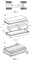
- FIG. 11 shows an exploded view of a battery 10 according to an embodiment of the present application.
- the battery 10 includes a covering 110, a thermal management component 13, a protective member 115, and a plurality of battery cells 20, where the covering 110 and the thermal management component 13 constitute an electrical chamber 11a for accommodating the battery cells 20; the thermal management component 13 and the protective member 115 form a collection chamber 11b, so that when a pressure relief mechanism 213 of the battery cell 20 is actuated, emissions discharged from the battery cell 20 pass through the thermal management component 13 and enter the collection chamber 11b; and a first pressure relief zone 113 on the collection chamber 11b discharges the emissions.
- the first pressure relief zone 113 in the embodiment of the present application may be disposed on any one or more walls of the collection chamber 11b.
- the first pressure relief zone 113 may be disposed on the thermal management component 13, so that when the pressure relief mechanism 213 is actuated, the emissions discharged from the battery cell 20 are discharged to the collection chamber 11b through the thermal management component 13, and then discharged through the first pressure relief zone 113 disposed on the thermal management component 13 to prevent the battery 10 from exploding due to excessive air pressure or high temperature in the collection chamber 11b.
- the first pressure relief zone 113 in the embodiment of the present application may also be disposed on other walls of the collection chamber 11b, for example, it may also be disposed on the protective member 115.
- FIG. 12 shows a schematic diagram of a protective member 115 according to an embodiment of the present application
- FIG. 13 shows another cross-sectional view of a protective member 115 according to an embodiment of the present application.
- the protective member 115 in the embodiment of the present application includes a bottom wall 1151 and a plurality of side walls 1152 to form a hollow structure with an opening at one end, and the thermal management component 13 covers the opening to form the collection chamber 11b.
- the first pressure relief zone 113 may be disposed on the bottom wall 1151 and/or the plurality of side walls 1152 of the protective member 115.
- the first pressure relief zone 113 is usually disposed on the plurality of side walls 1152.
- the number of first pressure relief zones 113 and the area and shape of each first pressure relief zone 113 in the embodiment of the present application can be set according to actual applications. If the number of the first pressure relief zones 113 is set to be large, and the area of each first pressure relief zone 113 is set to be large, the structural strength of the protective member 115 will be affected, however, if the number of the first pressure relief zones 113 is set to be small, and the area of each first pressure relief zone 113 is set to be small, the discharge of emissions will be affected. Therefore, the number of the first pressure relief zones 113 and the area of each first pressure relief zone 113 can be set reasonably according to the size and strength requirements of the protective member 115.
- each first pressure relief zone 113 can also be flexibly set, and the shapes of the plurality of first pressure relief zones 113 can also be the same or different.
- all the first pressure relief zones 113 may be set to the same shape, such as a rectangle shown in FIGS. 11 to 13 , but the embodiment of the present application is not limited thereto.
- the first pressure relief zone 113 may be disposed on one or more side walls 1152 of the plurality of side walls 1152, and one or more first pressure relief zones 113 may be disposed on each side wall 1152.
- the plurality of first pressure relief zones 113 can be uniformly arranged on each side wall 1152, so that the protective member 115 receives uniform force, and the structural strength of the protective member 115 is ensured.
- the first pressure relief zone 113 in the embodiment of the present application may be implemented in a variety of ways.
- the first pressure relief zone 113 may be a through hole.
- the protective member 115 is provided with at least one first through hole, and the first pressure relief zone 113 includes the first through hole.
- the first pressure relief zone 113 may also be a weakened zone on the protective member 115.
- at least one first weakened zone is disposed on the protective member 115, and the first weakened zone is capable of being damaged by the emissions in the collection chamber 11b when the pressure relief mechanism 213 is actuated, so that the emissions are discharged from the collection chamber 11b.
- the first pressure relief zone 113 includes the first weakened zone.
- the first weakened zone in the embodiment of the present application may be a groove on the protective member 115, and a bottom wall of the groove has a thickness smaller than a thickness of another region on the protective member 115, thereby forming the first weakened zone.
- an opening of the groove may face the inside of the collection chamber 11b or the outside of the collection chamber 11b; and the groove may include an indentation on the protective member 115.
- the first weakened zone is also directly an indentation on the protective member 115.
- the first weakened zone in the embodiment of the present application may also be a region where a temperature-sensitive material is located, that is, a material of the first weakened zone is a temperature-sensitive material, and the temperature-sensitive material is used to be melted when a temperature reaches a threshold, that is, a melting point of the material of the first weakened zone is set to be lower than a melting point of a material of another region on the protective member 115 other than the first weakened zone, so that the first weakened zone made of the temperature-sensitive material can be melted when the temperature of the emissions reaches a certain value.
- the material of the first weakened zone can be selected reasonably according to the temperature of the emissions discharged when the battery cell 20 suffers from thermal runaway.
- the discharged emissions can usually reach a temperature between 400° C and 800°C, and after passing through the thermal management component 13, due to the cooling effect of the thermal management component 13, the high-temperature emissions can reach a temperature between 200°C to 400°C when reaching the protective member 115.
- the melting point of the material of the first weakened zone may be set to be less than or equal to 200°C.
- the material of the first weakened zone may be a tin alloy material, or may also be a polypropylene engineering plastic material, so that when the temperature reaches 200°C, the first weakened zone can be melted immediately, and further, the emissions can be smoothly discharged from the collection chamber 11b through the melted region.
- choosing a temperature-sensitive material to set the first weakened zone can ensure the mechanical strength of the first weakened zone, and ensure the collision safety performance of the box 11 during the use of the battery 10; and the use of temperature-sensitive material to set the first weakened zone can implement when the gas pressure in the collection chamber 11b is insufficient, the first weakened zone can be melted quickly only by the temperature change in the collection chamber 11b.
- the use of temperature-sensitive material to set the first weakened zone can discharge the emissions more timely, and enhance the safety of the battery 10 in use.
- a thickness of the first weakened zone made of the temperature-sensitive material is usually selected to be consistent with a thickness of another region. For example, when the first weakened zone is disposed on the plurality of side walls 1152, wall thicknesses of the plurality of side walls 1152 at the first weakened zone are equal to wall thicknesses of the plurality of side walls 1152 at another region.
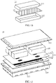
- FIG. 14 shows an exploded view of a thermal management component 13 according to an embodiment of the present application
- FIG. 15 shows a top view of a thermal management component 13 and a protective member 115 after installation according to an embodiment of the present application
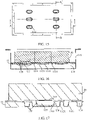
- FIG. 16 is a schematic cross-sectional view of a thermal management component 13 and a protective member 115 after installation along an A-A' direction shown in FIG. 15
- FIG. 17 is a partial enlarged view of a region A in FIG. 16
- FIG. 18 is a schematic cross-sectional view of a thermal management component 13 and a protective member 115 after installation along a B-B' direction shown in FIG. 15 .
- the thermal management component 13 in the embodiment of the present application is provided with a flow channel 134, which is configured to accommodate a fluid, and the flow channel 134 may be damaged by the emissions discharged from the battery cell 20 when the pressure relief mechanism 213 is actuated, so that the fluid is discharged from the inside of the flow channel 134; the thermal management component 13 may also be provided with a second pressure relief zone 133, so that when the pressure relief mechanism 213 is actuated, the emissions discharged from the battery cell 20 is capable of passing through the second pressure relief zone 133 and being discharged to the collection chamber 11b.
- the second pressure relief zone 133 in the embodiment of the present application can be set according to the position and size of the pressure relief mechanism 213.
- the second pressure relief zone 133 may be arranged opposite to the pressure relief mechanism 213, or an area of the second pressure relief zone 133 may also be set to be larger than an area of the pressure relief mechanism 213.
- the shape of the second pressure relief zone 133 may also be set according to the shape and area of the pressure relief mechanism 213.
- the shape of the second pressure relief zone 133 and the shape of the pressure relief mechanism 213 are the same, and both are in a racetrack shape shown in FIG. 14 and FIG. 15 , but the embodiment of the present application is not limited thereto.
- the size, position, and shape of the flow channel 134 in the embodiment of the present application can be set according to actual applications. As shown in FIGS. 14 to 18 , the flow channel 134 in the embodiment of the present application may be configured as a long strip. In order to enable the emissions discharged from the battery cell 20 to pass through the second pressure relief zone 133 and damage the flow channel 134 when the pressure relief mechanism 213 is actuated, so that the fluid is discharged from the flow channel 134 to reduce the temperature of the emissions, the flow channel 134 may be disposed around the second pressure relief zone 133, and cross-sectional shapes or sizes of the flow channel 134 at different positions may be the same or different, but the embodiment of the present application is not limited thereto.
- the thermal management component 13 in the embodiment of the present application may include a first thermally conductive plate 131 and a second thermally conductive plate 132.
- the first thermally conductive plate 131 is located between a first wall 21a where the pressure relief mechanism 213 is located and the second thermally conductive plate 132, and the first thermally conductive plate 131 is attached to the first wall 21a, and the first thermally conductive plate 131 is adhered to the second thermally conductive plate 132.
- the second thermally conductive plate 132 has a first groove 1321 with an opening facing the first thermally conductive plate 131, and the first groove 1321 and the first thermally conductive plate 131 form the flow channel 134.
- the size of one or more first grooves 1321 disposed on the second thermally conductive plate 132 may be the same or different, and the embodiment of the present application is not limited thereto.
- the first thermally conductive plate 131 is attached to the first wall 21a of the battery cell 20 may include the first thermally conductive plate 131 directly contacts the first wall 21a, or may include the first thermally conductive plate 131 is connected to the first wall 21a through a thermally conductive adhesive or other substances to realize the heat exchange between the first thermally conductive plate 131 and the first wall 21a of the battery cell 20.
- a second weakened zone 135 may be disposed on a wall of the flow channel 134, so that when the pressure relief mechanism 213 is actuated, the flow channel 134 is more likely to be damaged, that is, the flow channel 134 can be damaged at the second weakened zone 135, and the fluid in the flow channel 134 flows out to reduce the temperature of the emissions.
- the second weakened zone 135 may be implemented in a variety of ways.
- the second weakened zone 135 may be an indentation on the wall of the flow channel 134; or, the second weakened zone 135 may also be made of a temperature-sensitive material, that is, a melting point of a material of the second weakened zone 135 is lower than a melting point of a material of another region on the flow channel 134 other than the second weakened zone 135, so that the second weakened zone 135 can be melted when the temperature reaches a certain value.
- the material of the second weakened zone 135 can be selected according to the temperature of the emissions discharged from the battery cell 20.
- the material of the second weakened zone 135 can thus be selected from a material with a melting point less than or equal to 400°C.
- the emissions can melt the second weakened zone 135 and cause the second weakened zone 135 to be damaged.
- the second weakened zone 135 may be made of a tin alloy material, or may also be made of a polypropylene engineering plastic material.
- a wall thickness of the flow channel 134 at the second weakened zone 135 is usually set to be equal to a wall thickness of the flow channel 134 at another region, so as to prevent the second weakened zone 135 from being damaged in advance when the battery cell 20 does not suffer from thermal runaway during the use of the battery 10.
- the second weakened zone 135 may be made of a tin alloy material, and the remaining region of the flow channel 134 may be made of an aluminum material.
- the thicknesses of the two can be set to be the same, and they can be connected by welding or structural glue, but the embodiment of the present application is not limited thereto.
- adopting a temperature-sensitive material to configure the second weakened zone 135 can ensure the structural strength of the flow channel 134, and ensures the structural strength of the thermal management component 13 as well, so that during the normal use of the battery 10, the second weakened zone 135 is not easy to be damaged; and when the second weakened zone 135 is configured by a groove, air pressure acting on the surface of the second weakened zone 135 needs to be large enough.
- the temperature-sensitive material is adopted to configure the second weakened zone 135 to induce the temperature change when the gas pressure is insufficient, so that the second weakened zone 135 is quickly melted.
- the temperature-sensitive material is adopted to configure the second weakened zone 135 so that the flow channel 134 can be damaged in a more timely manner, thereby realizing the timeliness of reducing the temperature of the battery cell 20 that suffers from thermal runaway, and enhancing the safety of the battery 10.
- the melting point of the material of the second weakened zone 135 can thus be set to be larger, which can not only ensure the strength of the flow channel 134, but also enable the second weakened zone 135 to be melted when the emissions contact the second weakened zone 135, so that the fluid in the flow channel 134 can be discharged to reduce the temperature of the battery cell 20 that suffers from thermal runaway, the emissions as well as the box 11, and when the emissions with reduced temperature enter the collection chamber 11b, the temperature has already dropped.
- the melting point of the material of the second weakened zone 135 can be set to be smaller than the melting point of the material of the first weakened zone that the first pressure relief zone 113 includes, so that the emissions with reduced temperature can melt the material of the first pressure relief zone 113 and the emissions are discharged from the collection chamber 11b.
- the shape and area of the second weakened zone 135 in the embodiment of the present application may be set according to actual applications.
- the area of the second weakened zone 135 should not be set to be too large, because the second weakened zone 135 with a large area will cause the flow channel 134 to be excessively weak, and the mechanical strength of the flow channel 134 cannot be guaranteed; and when the pressure relief mechanism 213 is actuated, if the second weakened zone 135 with the large area is damaged, it will cause a waste of fluid in the flow channel 134.
- the position of the second weakened zone 135 in the embodiment of the present application may be set according to actual applications, and the second weakened zone 135 may be set at any one or more positions of the flow channel 134.
- the pressure relief mechanism 213 when the pressure relief mechanism 213 is actuated, the emissions of the battery cell 20 can be discharged to the collection chamber 11b through the second pressure relief zone 133 of the thermal management component 13. Therefore, the position of the second weakened zone 135 can be set according to the second pressure relief zone 133 so that the emissions passing through the second pressure relief zone 133 can damage the second weakened zone 135; in addition, the position of the second weakened zone 135 can also be reasonably set according to the position of the flow channel 134. Examples will be described below with reference to the accompanying drawings.
- the second pressure relief zone 133 in the embodiment of the present application may be a through hole on the thermal management component 13.
- the thermal management component 13 may be provided with a second through hole penetrating the first thermally conductive plate 131 and the second thermally conductive plate 132, and the second pressure relief zone 133 is the second through hole.
- a side wall of the second through hole may be a wall of the flow channel 134, and the second weakened zone 135 may be disposed on the side wall of the second through hole, so that the emissions of the battery cell 20 can damage the second weakened zone 135 on the hole wall when passing through the second through hole, and further, the fluid in the flow channel 134 can flow out smoothly.
- the second pressure relief zone 133 in the embodiment of the present application may also be a second groove 1311 on the thermal management component 13.
- the second pressure relief zone 133 is a second groove 1311 on the thermal management component 13 arranged opposite to the pressure relief mechanism 213, and a bottom wall of the second groove 1311 is configured to be damaged by the emissions discharged from the battery cell 20 when the pressure relief mechanism 213 is actuated, so that the emissions discharged from the battery cell 20 are discharged to the collection chamber 11b.
- an opening of the second groove 1311 may face the pressure relief mechanism 213 or may also face away from the pressure relief mechanism 213.
- the second weakened zone 135 can also be disposed on the side wall of the second groove 1311.
- the second groove 1311 in the embodiment of the present application can be implemented by the first thermally conductive plate 131 of the thermal management component 13, that is, the first thermally conductive plate 131 is recessed toward the second thermally conductive plate 132 in the second pressure relief zone 133, so as to form the second groove 1311.
- a size of the second groove 1311 can be set according to actual applications. For example, as shown in FIGS. 14 to 18 , a radial size of the second groove 1311 in the embodiment of the present application gradually decreases in a direction away from the pressure relief mechanism 213.
- Such a change in a hole diameter of the second groove 1311 can increase an area of a hole wall of the second groove 1311, which also increases a contact area between the emissions discharged from the battery cell 20 through the pressure relief mechanism 213 and the hole wall of the second groove 1311, and can reduce the temperature of more emissions; in addition, more emissions contact the hole wall of the second groove 1311, which can also enable the hole wall of the second groove 1311 to be more easily damaged by the emissions, especially when the hole wall of the second groove 1311 serves as the wall of the flow channel 134, the side wall of the second groove 1311 is damaged, so that the internal fluid can flow out quickly and reduce the temperature of the emissions.
- the radial size of the second groove 1311 may also remain unchanged in the direction away from the pressure relief mechanism 213.
- the second pressure relief zone 133 in the embodiment of the present application may also be a combination of the through hole and the groove.
- a third through hole 1312 is disposed on the bottom wall of the second groove 1311, and correspondingly, a fourth through hole 1322 is disposed on the second thermally conductive plate 132, so that the second pressure relief zone 133 can be formed, and the embodiment of the present application is not limited thereto.
- a third through hole 1312 is disposed on the bottom wall of the second groove 1311, but an cross-sectional area of the third through hole 1312 is smaller than an area of the bottom wall of the second groove 1311, and correspondingly, a fourth through hole 1322 is not disposed on the second thermally conductive plate 132, and by connecting a nonthrough hole region on the bottom wall of the second groove 1311 with the second thermally conductive plate 132, the second pressure relief zone 133 can be formed; or, no third through hole 1312 is disposed on the bottom wall of the second groove 1311, and correspondingly, a fourth through hole 1322 is disposed on the second thermally conductive plate 132, but an cross-sectional area of the fourth through hole 1322 is smaller than an area of the bottom wall of the second groove 1311, and by connecting the bottom wall of the second groove 1311 with a region around the fourth through hole 1322 on the second thermally
- the second groove 1311 in the embodiment of the present application may be disposed in the first groove 1321, so that the flow channel 134 is formed between the side wall of the first groove 1321 and the side wall of the second groove 1311; correspondingly, a second weakened zone 135 may be disposed on the side wall of the second groove 1311, and the emissions can damage the second weakened zone 135 on the side wall of the second groove 1311 while damaging the second pressure relief zone 133, so as to allow the fluid in the flow channel 134 to flow out and directly spray to the battery cell 20 suffering from thermal runaway, thereby directly realizing the effect of reducing the temperature of the battery cell 20 suffering from the thermal runaway.
- the second weakened zone 135 may also be located at other positions of the flow channel 134.
- the second weakened zone 135 may also be located on the side wall or the bottom wall of the first groove 1321 forming the flow channel 134.
- the second weakened zone 135 disposed on the side wall or bottom wall of the first groove 1321 is usually made of a temperature-sensitive material.
- the use of the temperature-sensitive material to configure the second weakened zone 135 can thus cause the emissions to quickly damage the wall of the flow channel 134 through the second weakened zone 135 disposed on the side wall or bottom wall of the first groove 1321, so that the fluid in the flow channel 134 flows directly into the collection chamber 11b, thereby further reducing the temperature of the protective member 115, and indirectly realizing the effect of reducing the temperature of the battery cell 20 suffering from the thermal runaway.
- a battery 10 in the embodiment of the present application includes an electrical chamber 11a and a collection chamber 11b.
- the electrical chamber 11a and the collection chamber 11b are respectively disposed on both sides of a thermal management component 13.
- a pressure relief mechanism 213 is actuated, discharged emissions can enter the collection chamber 11b through the thermal management component 13, and the emissions can be discharged out of the collection chamber 11b through a first pressure relief zone 113 disposed on the collection chamber 11b to relieve pressure and temperature inside the collection chamber 11b, thereby improving the safety of the battery 10 during use.
- a second weakened zone 135 may also be disposed on the thermal management component 13, for example, the second weakened zone 135 may be disposed on a flow channel 134, and the emissions discharged from the battery cell 20 through the pressure relief mechanism 213 can damage the second weakened zone 135, so that a fluid in the flow channel 134 can flow out to reduce the temperature of the battery cell 20, or reduce the temperature of the collection chamber 11b and the emissions in the collection chamber 11b, so as to further reduce the possibility of explosion of the battery 10.
- FIG. 19 shows a schematic flowchart of a method 300 for producing a box of a battery according to an embodiment of the present application.
- the method 300 may include: S310, providing an electrical chamber, the electrical chamber being configured to accommodate a plurality of battery cells, a battery cell including a pressure relief mechanism, and the pressure relief mechanism being configured to be actuated when an internal pressure or temperature of the battery cell reaches a threshold, to relieve the internal pressure; S320, providing a thermal management component, the thermal management component being configured to accommodate a fluid to adjust the temperature of the battery cell; and S330, providing a collection chamber, the collection chamber being configured to collect emissions discharged from the battery cell and passing through the thermal management component when the pressure relief mechanism is actuated, where the electrical chamber and the collection chamber are disposed on both sides of the thermal management component, the thermal management component is configured to separate the electrical chamber and the collection chamber, a wall of the collection chamber is provided with a first pressure relief zone, and the first pressure relief zone is configured to relieve the emissions in the collection chamber
- FIG. 20 shows a schematic block diagram of an apparatus 400 for producing a box of a battery according to an embodiment of the present application.
- the apparatus 400 may include: a provision module 410.
- the provision module 410 is configured to provide an electrical chamber, the electrical chamber being configured to accommodate a plurality of battery cells, a battery cell including a pressure relief mechanism, and the pressure relief mechanism being configured to be actuated when an internal pressure or temperature of the battery cell reaches a threshold, to relieve the internal pressure; provide a thermal management component, the thermal management component being configured to accommodate a fluid to adjust the temperature of the battery cell; and provide a collection chamber, the collection chamber being configured to collect emissions discharged from the battery cell and passing through the thermal management component when the pressure relief mechanism is actuated, where the electrical chamber and the collection chamber are disposed on both sides of the thermal management component, the thermal management component is configured to separate the electrical chamber and the collection chamber, a wall of the collection chamber is provided with a first pressure relief zone, and the first pressure relief zone is configured to relieve the emissions
Abstract
Description
- The present application relates to the field of battery technologies, and in particular, to a box of a battery, a battery, a power consumption device, and a method and apparatus for producing a box.
- Energy conservation and emission reduction are the key to the sustainable development of the automotive industry. In this case, electric vehicles have become an important component of the sustainable development of the automotive industry due to their advantages of energy conservation and environmental protection. For the electric vehicles, battery technology is an important factor for their development.
- In the development of the battery technology, in addition to improving the performance of a battery, safety is also an issue that cannot be ignored. If the safety of the battery cannot be guaranteed, the battery cannot be used. Therefore, how to enhance the safety of the battery is an urgent technical problem to be solved in the battery technology.
- The present application provides a box of a battery, a battery, a power consumption device, and a method and apparatus for producing a box, which can enhance the safety of the battery.
- In a first aspect, provided is a box of a battery, including: an electrical chamber, configured to accommodate a plurality of battery cells, a battery cell including a pressure relief mechanism, and the pressure relief mechanism being configured to be actuated when an internal pressure or temperature of the battery cell reaches a threshold, to relieve the internal pressure; a thermal management component, configured to accommodate a fluid to adjust the temperature of the battery cell; and a collection chamber, configured to collect emissions discharged from the battery cell and passing through the thermal management component when the pressure relief mechanism is actuated, where the electrical chamber and the collection chamber are disposed on both sides of the thermal management component, the thermal management component is configured to separate the electrical chamber and the collection chamber, a wall of the collection chamber is provided with a first pressure relief zone, and the first pressure relief zone is configured to relieve the emissions in the collection chamber.
- Therefore, in the box of the battery in the embodiment of the present application, the first pressure relief zone is disposed on the wall of the collection chamber, so that when the pressure relief mechanism is actuated, the emissions discharged by the battery cell through the pressure relief mechanism can be discharged in time through the first pressure relief zone on the wall of the collection chamber after entering the collection chamber, to relieve the pressure and temperature in the collection chamber, thereby enhancing the safety of the battery.
- In some embodiments, the thermal management component has a wall shared by the electrical chamber and the collection chamber.
- In some embodiments, the box includes: a protective member, where the protective member is configured to protect the thermal management component, and the protective member and the thermal management component form the collection chamber.
- In some embodiments, the protective member includes a bottom wall and a plurality of side walls to form a hollow structure with an opening at one end, and the thermal management component covers the opening to form the collection chamber.
- In some embodiments, the first pressure relief zone is disposed on the plurality of side walls.
- If the first pressure relief zone is disposed on the bottom wall of the protective member, the strength of the bottom wall of the protective member will be affected, and then during the use of the battery, it is not beneficial for the collision safety performance of the whole battery. Therefore, the first pressure relief zone is usually disposed on the side wall.
- In some embodiments, a plurality of the first pressure relief zones are disposed on each side wall of the plurality of side walls.
- The provision of the plurality of first pressure relief zones can speed up the discharge of the emissions from the collection chamber, but considering the structural strength of the protective member, it is not advisable to provide too many first pressure relief zones on each side wall.
- In some embodiments, the plurality of the first pressure relief zones are uniformly arranged on the each side wall.
- The first pressure relief zone is uniformly distributed on each side wall, so that the protective member can receive uniform force during use, and the structural strength of the protective member will not be affected due to the fact that the local strength of the protective member is too weak.
- In some embodiments, a first through hole is disposed on the protective member, and the first pressure relief zone includes the first through hole.
- The first pressure relief zone is set as a through hole, so that the emissions that enter the collection chamber can be quickly discharged through the through hole, which speeds up the discharge speed.
- In some embodiments, a first weakened zone is disposed on the protective member, the first weakened zone is configured to be damaged by the emissions in the collection chamber when the pressure relief mechanism is actuated, so that the emissions are discharged from the collection chamber, and the first pressure relief zone includes the first weakened zone.
- Compared with setting the first pressure relief zone as the first through hole, setting the first pressure relief zone as the first weakened zone can ensure that the collection chamber remains a relatively sealed state with the outside of the battery when the battery cells are normal and no thermal runaway occurs, thereby preventing external water vapor and dust from negatively affecting the use of the battery.
- In some embodiments, a melting point of a material of the first weakened zone is lower than a melting point of a material of another region on the protective member other than the first weakened zone.
- A temperature-sensitive material is adopted to set the first weakened zone so that when the pressure relief mechanism is actuated, the first weakened zone can still be damaged even when the pressure in the collection chamber is low, and thus the emissions from the battery cells can be discharged in time.
- In some embodiments, a melting point of a material of the first weakened zone is less than or equal to 200°C.
- Considering the thermal runaway of the battery cell, the discharged emissions can usually reach a temperature between 400°C and 800°C, and after passing through the thermal management component, the high-temperature emissions can reach a temperature between 200°C and 400°C when reaching the protective member. In order to enable the emissions reaching the protective member to melt the first weakened zone, the melting point of the material of the first weakened zone may be set to be less than or equal to 200°C.
- In some embodiments, the first weakened zone is disposed on the plurality of side walls, and wall thicknesses of the plurality of side walls at the first weakened zone are equal to wall thicknesses of the plurality of side walls at another region, so as to ensure the structural strength of the side walls.
- In some embodiments, the first weakened zone includes an indentation on the protective member.
- In some embodiments, a second pressure relief zone is disposed on the thermal management component so that when the pressure relief mechanism is actuated, the emissions discharged from the battery cell are capable of passing through the second pressure relief zone and being discharged to the collection chamber.
- In some embodiments, the second pressure relief zone is arranged opposite to the pressure relief mechanism.
- In this way, when the pressure relief mechanism is actuated, the discharged emissions can be directly discharged from the electrical chamber through the second pressure relief zone.
- In some embodiments, a flow channel is disposed on the thermal management component, and the flow channel is configured to accommodate the fluid and be damaged by the emissions discharged from the battery cell when the pressure relief mechanism is actuated, so that the fluid is discharged from the inside of the flow channel.
- In some embodiments, a second weakened zone is disposed on a wall of the flow channel, so that when the pressure relief mechanism is actuated, the flow channel is damaged at the second weakened zone. In this way, the fluid in the flow channel can be directly discharged, thereby reducing the temperature of the emissions.
- In some embodiments, the thermal management component includes a first thermally conductive plate and a second thermally conductive plate, the first thermally conductive plate is located between a first wall and the second thermally conductive plate and attached to the first wall, the first wall is a wall of the battery cell provided with the pressure relief mechanism, the first thermally conductive plate is adhered to the second thermally conductive plate, the second thermally conductive plate has a first groove with an opening facing the first thermally conductive plate, and the first groove and the first thermally conductive plate form the flow channel.
- In some embodiments, the second weakened zone is located on a side wall or a bottom wall of the first groove.
- In some embodiments, the second pressure relief zone is a second through hole on the thermal management component.
- The second pressure relief zone is set as a second through hole, so that the emissions discharged from the pressure relief mechanism can be quickly discharged to the collection chamber through the second through hole.
- In some embodiments, the second weakened zone is disposed on a side wall of the second through hole.
- A hole wall of the second through hole is a wall of the flow channel, so that when the emissions pass through the second through hole, the second weakened zone can be damaged, and further, the fluid in the flow channel is discharged to reduce the temperature of the emissions.
- In some embodiments, the second pressure relief zone is a second groove on the thermal management component that is arranged opposite to the pressure relief mechanism, a bottom wall of the second groove is configured to be damaged by the emissions discharged from the battery cell when the pressure relief mechanism is actuated, so as to discharge the emissions discharged from the battery cell to the collection chamber.
- The second pressure relief zone is set as a groove, so that when the battery cell suffers from thermal runaway, the pressure relief mechanism has enough space to relieve the pressure, and when the battery cell is working normally, the electrical chamber and the collection chamber are not in communication with each other, and the electrical chamber will not be affected by the collection chamber.
- In some embodiments, a radial size of the second groove gradually decreases in a direction away from the pressure relief mechanism.
- Such a change in a hole diameter of the second groove can increase an area of a hole wall of the second groove, which also increases a contact area between the emissions discharged from the battery cell through the pressure relief mechanism and the hole wall of the second groove, and can reduce the temperature of more emissions; in addition, more emissions contact the hole wall of the second groove, which can also enable the hole wall of the second groove to be more easily damaged by the emissions, especially when the hole wall of the second groove serves as the wall of the flow channel, the side wall of the second groove is damaged, so that the internal fluid can flow out quickly and reduce the temperature of the emissions.
- In some embodiments, the first thermally conductive plate is recessed toward the second thermally conductive plate in the second pressure relief zone to form the second groove.
- In some embodiments, the second groove is disposed in the first groove so that the flow channel is formed between the side wall of the first groove and a side wall of the second groove.
- In some embodiments, the second weakened zone is disposed on a side wall of the second groove.
- That is, the side wall of the second groove is the wall of the flow channel. When the emissions damage the bottom wall of the second groove and enter the collection chamber, they will also damage the second weakened zone on the side wall of the second groove, so that the fluid in the flow channel flows out, thereby reducing the temperature of the emissions.
- In some embodiments, a melting point of a material of the second weakened zone is lower than a melting point of a material of another region on the flow channel other than the second weakened zone.
- In some embodiments, a melting point of a material of the second weakened zone is less than or equal to 400°C.
- Considering that when the battery cell suffers from thermal runaway, the discharged emissions can usually reach a temperature between 400°C and 800°C, the material of the second weakened zone can thus be selected from a material with a melting point less than or equal to 400°C.
- In some embodiments, a wall thickness of the flow channel at the second weakened zone is equal to a wall thickness of the flow channel at another region of the flow channel, so as to ensure the strength of the flow channel on the thermal management component.
- In some embodiments, a melting point of a material of the second weakened zone is smaller than a melting point of a material of the first weakened zone.
- Considering that after the emissions are discharged from the pressure relief mechanism, they first contact the thermal management component, the melting point of the material of the second weakened zone on the thermal management component can thus be set to be higher, which can also avoid excessive weakness of the thermal management component; and when the emissions enter the collection chamber through the thermal management component, since the thermal management component has already reduced the temperature of the emissions, the emissions cool down quickly, and the melting point of the material of the first weakened zone on the collection chamber can be set to be lower. As a result, the first weakened zone can be quickly melted, and the emissions can be discharged out of the collection chamber.
- In some embodiments, the box further includes a covering, the covering is a hollow structure with an opening at one end, and the thermal management component covers the opening of the covering to form the electrical chamber.
- In a second aspect, provided is a battery, including: a plurality of battery cells, at least one battery cell of the plurality of battery cells including a pressure relief mechanism, and the pressure relief mechanism being configured to be actuated when an internal pressure or temperature of the battery cell provided with the pressure relief mechanism reaches a threshold, to relieve the internal pressure; and the box of the battery in the first aspect, the box being configured to accommodate the plurality of battery cells.
- In a third aspect, provided is a power consumption device, including: the battery in the second aspect, the battery being configured to provide electrical energy.
- In some embodiments, the power consumption device is a vehicle, a ship or a spacecraft.
- In a fourth aspect, provided is a method for producing a box of a battery, including: providing an electrical chamber, the electrical chamber being configured to accommodate a plurality of battery cells, a battery cell including a pressure relief mechanism, and the pressure relief mechanism being configured to be actuated when an internal pressure or temperature of the battery cell reaches a threshold, to relieve the internal pressure; providing a thermal management component, the thermal management component being configured to accommodate a fluid to adjust the temperature of the battery cell; and providing a collection chamber, the collection chamber being configured to collect emissions discharged from the battery cell and passing through the thermal management component when the pressure relief mechanism is actuated, where the electrical chamber and the collection chamber are disposed on both sides of the thermal management component, the thermal management component is configured to separate the electrical chamber and the collection chamber, a wall of the collection chamber is provided with a first pressure relief zone, and the first pressure relief zone is configured to relieve the emissions in the collection chamber.
- In a fifth aspect, provided is an apparatus for producing a box of a battery, including: a module for executing the above method in the fourth aspect.
-
-
FIG. 1 is a schematic structural diagram of a vehicle disclosed in an embodiment of present application; -
FIG. 2 is a schematic diagram of an exploded structure of a battery disclosed in an embodiment of the present application; -
FIG. 3 is a schematic diagram of a partial structure of a battery module disclosed in an embodiment of the present application; -
FIG. 4 is an exploded view of a battery cell disclosed in an embodiment of the present application; -
FIG. 5 is a cross-sectional view of a battery disclosed in an embodiment of the present application; -
FIG. 6 is an exploded view of an electrical chamber disclosed in an embodiment of the present application; -
FIG. 7 is another exploded view of an electrical chamber disclosed in an embodiment of the present application; -
FIG. 8 is a schematic structural diagram of a box of a battery disclosed in an embodiment of the present application; -
FIG. 9 is another schematic structural diagram of a box of a battery disclosed in an embodiment of the present application; -
FIG. 10 is an exploded view of another box of a battery disclosed in an embodiment of the present application; -
FIG. 11 is another exploded view of a battery disclosed in an embodiment of the present application; -
FIG. 12 is a schematic diagram of a protective member disclosed in an embodiment of the present application; -
FIG. 13 is another schematic cross-sectional view of a protective member disclosed in an embodiment of the present application; -
FIG. 14 is an exploded view of a thermal management component disclosed in an embodiment of the present application; -
FIG. 15 is a top view of a thermal management component and a protective member after installation disclosed in an embodiment of the present application; -
FIG. 16 is a schematic cross-sectional view of a thermal management component and a protective member disclosed in an embodiment of the present application; -
FIG. 17 is a partial enlarged view of a cross-section of a thermal management component and a protective member disclosed in an embodiment of the present application; -
FIG. 18 is another schematic cross-sectional view of a thermal management component and a protective member disclosed in an embodiment of the present application; -
FIG. 19 is a schematic flowchart of a method for producing a box of a battery disclosed in an embodiment of the present application; and -
FIG. 20 is a schematic block diagram of an apparatus for producing a box of a battery disclosed in an embodiment of the present application. - In the drawings, the drawings are not drawn to actual scale.
- Implementation manners of the present application will be further described below in detail with reference to the accompanying drawings and embodiments. The detailed description of the following embodiments and the accompanying drawings are used to exemplarily illustrate principles of the present application, but cannot be used to limit the scope of the present application, that is, the present application is not limited to the described embodiments.
- In the description of the present application, it should be noted that, unless otherwise provided, "a plurality of' means more than two (including two); and orientations or positional relationships indicated by terms such as "up", "down", "left", "right", "inside", and "outside" are merely for convenience of describing the present application and for simplifying the description, rather than for indicating or implying that an apparatus or element indicated must have a specific orientation, and must be constructed and operated in a specific orientation, which thus may not be understood as limitation to the present application. In addition, the terms "first", "second", and "third" are only intended for the purpose of description, and shall not be understood as an indication or implication of relative importance. "Vertical" is not strictly vertical, but within an allowable range of error. "Parallel" is not strictly parallel, but within an allowable range of error.
- The orientation words appearing in the following description are all directions shown in the drawings, and do not limit the specific structure of the present application. In the description of the present application, it should be further noted that, unless explicitly specified and defined otherwise, terms "installation", "interconnection", "connection" and "attachment" should be understood broadly, for example, they may either be a fixed connection, or a detachable connection, or an integrated connection; and they may either be a direct connection, or an indirect connection through an intermediary. Those of ordinary skill in the art may understand the specific meanings of the foregoing terms in the present application according to specific conditions.
- In the present application, a battery cell may include a primary battery, a secondary battery, such as a lithium-ion battery, a lithium-sulfur battery, a sodium/lithium-ion battery, a sodium-ion battery or a magnesium-ion battery, which is not limited in the embodiments of the present application. The battery cell may be cylindrical, flat, cuboid or in another shape, which is also not limited in the embodiments of the present application. The battery cell is generally divided into three types according to the way of packaging: a cylindrical battery cell, a square battery cell and a pouch battery cell, which is also not limited in the embodiments of the present application.
- The battery mentioned in the embodiment of the present application refers to a single physical module that includes one or more battery cells to provide a higher voltage and capacity. For example, the battery mentioned in the present application may include a battery module or a battery pack. The battery pack generally includes a box for encapsulating one or more battery cells. The box can prevent liquid or other foreign matters from affecting the charging or discharging of the battery cell.
- The battery cell includes an electrode assembly and an electrolytic solution, and the electrode assembly includes a positive electrode sheet, a negative electrode sheet and a separator. The operation of a battery cell mainly relies on movement of metal ions between the positive electrode sheet and the negative electrode sheet. The positive electrode sheet includes a positive electrode current collector and a positive electrode active material layer. The positive electrode active material layer is coated on a surface of the positive electrode current collector, and a current collector not coated with the positive electrode active material layer protrudes from the current collector coated with the positive electrode active material layer and serves as a positive tab. In an example of a lithium-ion battery, a material of the positive electrode current collector may be aluminum, and the positive electrode active material may be lithium cobalt oxides, lithium iron phosphate, ternary lithium, lithium manganate, or the like. The negative electrode sheet includes a negative electrode current collector and a negative electrode active material layer. The negative electrode active material layer is coated on a surface of the negative electrode current collector, and a current collector not coated with the negative electrode active material layer protrudes from the current collector coated with the negative electrode active material layer and serves as a negative tab. A material of the negative electrode current collector may be copper, and the negative electrode active material may be carbon, silicon, or the like. In order to ensure that no fusing occurs when a large current passes, there are a plurality of positive tabs which are stacked together, and there are a plurality of negative tabs which are stacked together. A material of the separator may be PP, PE, or the like. In addition, the electrode assembly may be a winding structure or a laminated structure, and the embodiments of the present application are not limited thereto. With the development of the battery technology, it is necessary to consider design factors in multiple aspects simultaneously, such as energy density, cycle life, discharge capacity, C-rate and other performance parameters. In addition, safety of the battery should also be considered.
- For a battery, a main safety hazard comes from the charging and discharging process, and in order to improve safety performance of the battery, a battery cell is generally provided with a pressure relief mechanism. The pressure relief mechanism refers to an element or component that is actuated when an internal pressure or temperature of the battery cell reaches a predetermined threshold, to relieve the internal pressure or temperature. The predetermined threshold may be adjusted according to different design requirements. The predetermined threshold may depend on the material of one or more of the positive electrode sheet, the negative electrode sheet, the electrolytic solution and the separator in the battery cell. The pressure relief mechanism may adopt, for example, a pressure-sensitive or temperature-sensitive element or component. That is, when the internal pressure or temperature of the battery cell reaches a predetermined threshold, the pressure relief mechanism is actuated, so as to form a channel for relieving the internal pressure or temperature.
- The "actuated" mentioned in the present application means that the pressure relief mechanism generates an action, so that the internal pressure and temperature of the battery cell can be relieved. The action generated by the pressure relief mechanism may include but be not limited to: at least a portion of the pressure relief mechanism being fractured, torn or melted, and so on. After the pressure relief mechanism is actuated, high-temperature and high-pressure substances inside the battery cell will be discharged outwards from the pressure relief mechanism as emissions. In this way, the pressure of the battery cell can be relieved at a controllable pressure or temperature, thereby avoiding potentially more serious accidents.
- The emissions from the battery cell mentioned in the present application include but are not limited to: an electrolytic solution, a dissolved or split positive and negative electrode sheet, fragments of a separator, a high-temperature and high-pressure gas generated by reaction, flames, or the like.
- The pressure relief mechanism on the battery cell has an important impact on the safety of the battery. For example, when a short circuit, overcharge and other phenomena occur in the battery cell, it may lead to thermal runaway inside the battery cell, resulting in a sudden increase in pressure or temperature. In this case, the internal pressure and temperature can be released outward through the actuation of the pressure relief mechanism, to prevent the battery cell from exploding and catching fire.
- In the current design solutions of the pressure relief mechanism, the main concern is to release the high pressure and high heat inside the battery cell, i.e., to discharge the emissions to the outside of the battery cell. However, in order to ensure an output voltage or current of the battery, a plurality of battery cells are often required and the plurality of battery cells are electrically connected to each other via a bus component. The emissions discharged from the inside of a battery cell may cause a short circuit of the other battery cells. For example, when discharged metal scraps are electrically connected to two bus components, the battery will be short-circuited, thereby posing a potential safety hazard. Moreover, the high-temperature and high-pressure emissions are discharged in a direction in which the pressure relief mechanism of the battery cell is disposed, and more specifically, may be discharged in a direction of a region in which the pressure relief mechanism is actuated. The strength and destructive power of such emissions may be huge, or may even be great enough to break through one or more structures in this direction, causing further safety problems.
- In view of this, a battery in an embodiment of the present application may also be provided with a thermal management component, a surface of the thermal management component is attached to a surface of a battery cell where a pressure relief mechanism is disposed, and a pressure relief zone may also be disposed on the thermal management component. By using the management component, the inside of a box of the battery can be separated into an electrical chamber for accommodating the battery cell and a collection chamber for collecting emissions. When the pressure relief mechanism is actuated, the emissions from the battery cell can enter the collection chamber, thereby reducing the impact of the emissions on a bus component in the electrical chamber, and further, enhancing the safety of the battery; and since the emissions of the battery cell are collected through the collection chamber, the high-temperature and high-pressure emissions are buffered, and pressure and temperature of the emissions are reduced to some extent, thereby reducing the destructive power to other structures, and further enhancing the safety of the battery.
- However, if the emissions entering the collection chamber cannot be discharged in time, thermal diffusion may be likely to be caused, and the emissions may cause other battery cells to suffer from thermal runaway as well, which in turn causes the battery to explode.
- In order to solve this problem, an embodiment of the present application provides a box of a battery, the box includes an electrical chamber, a thermal management component, and a collection chamber; and a first pressure relief zone is disposed on the collection chamber, and the first pressure relief zone is configured to relieve emissions in the collection chamber, so that the emissions can be discharged from the collection chamber in time, thereby relieving pressure and temperature in the collection chamber, and preventing explosion.
- It should be understood that the thermal management component in the embodiment of the present application may be configured to accommodate a fluid to adjust the temperature of a plurality of battery cells. The fluid here may be a liquid or a gas, and the temperature adjustment means heating or cooling the plurality of battery cells. In a case of cooling or lowering the temperature of the battery cells, the thermal management component is configured to accommodate a cooling fluid to lower the temperature of the plurality of battery cells. In this case, the thermal management component may also be called a cooling component, a cooling system, a cooling plate, or the like. The fluid accommodated therein may also be called a cooling medium or a cooling fluid, and more specifically, may be called a cooling liquid or a cooling gas. In addition, the thermal management component may also be configured for heating to raise the temperature of the plurality of battery cells, which is not limited in the embodiment of the present application. Optionally, the fluid may flow in a circulating manner to achieve a better temperature adjustment effect. Optionally, the fluid may be water, a mixture of water and ethylene glycol, air, or the like.
- In addition, when the pressure relief mechanism is actuated, the emissions discharged from the battery cell can be discharged through a pressure relief zone of the thermal management component, and the thermal management component can also lower the temperature of the battery cell to avoid the battery cell from exploding.
- The electrical chamber in the embodiment of the present application may be configured to accommodate a plurality of battery cells, and may also be configured to accommodate a bus component. The electrical chamber may be sealed or unsealed. The electrical chamber provides an installation space for the battery cells and the bus component. In some embodiments, a structure configured to fix the battery cells may also be disposed in the electrical chamber. The shape of the electrical chamber may be determined according to the plurality of battery cells and the bus component accommodated. In some embodiments, the electrical chamber may be a cube with six walls. Since the battery cells in the electrical chamber form higher voltage output through electrical connection, the electrical chamber may also be called a "high-voltage chamber".
- The bus component is configured to implement electrical connection between the plurality of battery cells, such as parallel connection, series connection or series-parallel connection. The bus component may implement the electrical connection between the battery cells by connecting electrode terminals of the battery cells. In some embodiments, the bus component may be fixed to the electrode terminals of the battery cells by means of welding. Analogous to the "high-voltage chamber", the electrical connection formed by the bus component may also be called "high-voltage connection".
- The collection chamber in the embodiment of the present application is configured to collect the emissions, and may be sealed or non-sealed. In some embodiments, the collection chamber may contain air or another gas. In the collection chamber, there is no electrical connection to the voltage output. Corresponding to the "high-voltage chamber", the collection chamber may also be called a "low-voltage chamber". Optionally, or additionally, the collection chamber may also contain a liquid, such as a cooling medium, or is provided with a component for accommodating the liquid so as to further lower the temperature of the emissions entering the collection chamber. Further, optionally, the gas or liquid in the collection chamber flows in a circulating manner.
- Technical solutions described in embodiments of the present application are all applicable to various apparatuses using batteries, such as mobile phones, portable devices, notebook computers, electromobiles, electronic toys, electric tools, electric vehicles, ships and spacecrafts. For example, the spacecrafts include airplanes, rockets, space shuttles, spaceships, and the like.
- It should be understood that the technical solutions described in the embodiments of the present application are not only applicable to the devices described above, but also applicable to all devices using batteries. However, for brief description, the following embodiments are all described by an example of an electric vehicle.
- For example, as shown in
FIG. 1, FIG. 1 is a schematic structural diagram of a vehicle 1 according to an embodiment of the present application. The vehicle 1 may be a fuel-powered vehicle, a gas-powered vehicle or a new energy vehicle, and the new energy vehicle may be a battery electric vehicle, a hybrid vehicle, an extended-range vehicle, or the like. The vehicle 1 may be internally provided with amotor 40, acontroller 30 and abattery 10, and thecontroller 30 is configured to control thebattery 10 to supply power to themotor 40. For example, thebattery 10 may be disposed at the bottom, head or tail of the vehicle 1. Thebattery 10 may be used for power supply of the vehicle 1. For example, thebattery 10 may serve as an operation power source of the vehicle 1 for a circuit system of the vehicle 1, for example, for a working power demand of the vehicle 1 during startup, navigation and running. In another embodiment of the present application, thebattery 10 may serve not only as an operation power source of the vehicle 1, but also as a driving power source of the vehicle 1, replacing or partially replacing fuel or natural gas to provide driving power for the vehicle 1. - In order to meet different power demands, the
battery 10 may include a plurality ofbattery cells 20, where the plurality ofbattery cells 20 may be in series connection, parallel connection or series-parallel connection. The series-parallel connection refers to a combination of series connection and parallel connection. Thebattery 10 may also be referred to as a battery pack. Optionally, the plurality ofbattery cells 20 may be first connected in series, in parallel, or in series and parallel to constitute abattery module 200, and then the plurality ofbattery modules 200 are connected in series, in parallel, or in series and parallel to constitute thebattery 10. That is, the plurality ofbattery cells 20 may directly constitute thebattery 10, or may first constitute thebattery module 200, and then thebattery modules 200 constitute thebattery 10. - For example, as shown in
FIG. 2, FIG. 2 is a schematic structural diagram of abattery 10 according to an embodiment of the present application, and thebattery 10 may include at least onebattery module 200. Thebattery module 200 includes a plurality ofbattery cells 20. Thebattery 10 may further include abox 11 with the inside thereof being a hollow structure, and the plurality ofbattery cells 10 are accommodated in thebox 11. As shown inFIG. 2 , the box may include two portions, which are referred to as afirst portion 111 and asecond portion 112, respectively, and thefirst portion 111 and thesecond portion 112 are fastened together. Shapes of thefirst portion 111 and thesecond portion 112 may be determined according to a combined shape ofbattery modules 200, and at least one of thefirst portion 111 and thesecond portion 112 has one opening. For example, as shown inFIG. 2 , thefirst portion 111 and thesecond portion 112 each may be a hollow cuboid and each have only one surface as an opening surface, an opening of thefirst portion 111 is arranged opposite to an opening of thesecond portion 112, and thefirst portion 111 and thesecond portion 112 are fastened to each other to form thebox 11 with a closed chamber. For another example, different from that shown inFIG. 2 , only one of thefirst portion 111 and thesecond portion 112 may be a hollow cuboid with an opening, and the other may be in a plate shape to cover the opening. For example, in an example that thesecond portion 112 is a hollow cuboid and has only one surface as an opening surface and thefirst portion 111 is in a plate shape, an opening of thesecond portion 112 is covered by thefirst portion 111 to form thebox 11 with a closed chamber, and the chamber may be configured to accommodate the plurality ofbattery cells 20. The plurality ofbattery cells 20 are combined in parallel connection or series connection or series-parallel connection and are then placed in thebox 11 formed by fastening thefirst portion 111 to thesecond portion 112. - Optionally, the
battery 10 may further include other structures, which will not be described in detail herein. For example, thebattery 10 may further include a bus component. The bus component is configured to implement electrical connection between the plurality ofbattery cells 20, such as parallel connection, series connection or series-parallel connection. Specifically, the bus component may implement the electrical connection between thebattery cells 20 by connecting electrode terminals of thebattery cells 20. Further, the bus component may be fixed to the electrode terminals of thebattery cells 20 by means of welding. Electric energy of the plurality ofbattery cells 20 may be further led out through an electrically conductive mechanism passing through thebox 11. - According to different power demands, the number of
battery cells 20 in thebattery module 200 may be set to any value. The plurality ofbattery cells 20 may be connected in series, in parallel or in series and parallel to achieve larger capacity or power. Since the number of thebattery cells 20 included in eachbattery 10 may be large, thebattery cells 20 are arranged in groups for convenience of installation, and each group ofbattery cells 20 constitute thebattery module 200. The number ofbattery cells 20 included in thebattery module 200 is not limited and may be set according to demands. For example,FIG. 3 is an example of abattery module 200. Thebattery 10 may include a plurality ofbattery modules 200, and thesebattery modules 200 may be connected in series, in parallel or in series and parallel. -
FIG. 4 is a schematic structural diagram of abattery cell 20 according to an embodiment of the present application. Thebattery cell 20 includes one ormore electrode assemblies 22, ahousing 211 and acover plate 212. Thehousing 211 and thecover plate 212 form ashell 21. A wall of thehousing 211 and thecover plate 212 are both referred to as a wall of thebattery cell 20. Thehousing 211 is shaped according to the combined shape of the one ormore electrode assemblies 22. For example, thehousing 211 may be a hollow cuboid or cube or cylinder, and one surface of thehousing 211 has an opening, so that the one ormore electrode assemblies 22 may be placed in thehousing 211. For example, when thehousing 211 is a hollow cuboid or cube, one plane of thehousing 211 is an opening surface, that is, the plane does not have a wall, so that the inside and outside of thehousing 211 are in communication with each other. When thehousing 211 is a hollow cylinder, an end surface of thehousing 211 is an opening surface, that is, the end surface does not have a wall, so that the inside and outside of thehousing 211 are in communication with each other. Thecover plate 212 covers the opening and is connected to thehousing 211 to form a closed cavity in which theelectrode assemblies 22 are placed. Thehousing 211 is filled with an electrolyte, such as an electrolytic solution. - The
battery cell 20 may further include twoelectrode terminals 214, and the twoelectrode terminals 214 may be disposed on thecover plate 212. Thecover plate 212 is generally in the shape of a flat plate, the twoelectrode terminals 214 are fixed on the flat plate face of thecover plate 212, and the twoelectrode terminals 214 are afirst electrode terminal 214a and asecond electrode terminal 214b, respectively. Polarities of the twoelectrode terminals 214 are opposite. For example, when thefirst electrode terminal 214a is a positive electrode terminal, thesecond electrode terminal 214b is a negative electrode terminal. Eachelectrode terminal 214 is correspondingly provided with a connectingmember 23, which is located between thecover plate 212 and theelectrode assembly 22 and configured to electrically connect theelectrode assembly 22 to theelectrode terminal 214. - As shown in
FIG. 4 , eachelectrode assembly 22 has afirst tab 221a and asecond tab 222a. Thefirst tab 221a and thesecond tab 222a have opposite polarities. For example, when thefirst tab 221a is a positive tab, thesecond tab 222a is a negative tab. Thefirst tab 221a of the one ormore electrode assemblies 22 is connected to one electrode terminal through one connectingmember 23, and thesecond tab 222a of the one ormore electrode assemblies 22 is connected to the other electrode terminal through the other connectingmember 23. For example, thefirst electrode terminal 214a having a positive polarity is connected to the positive tab through one connectingmember 23, and thesecond electrode terminal 214b having a negative polarity is connected to the negative tab through the other connectingmember 23. - In the
battery cell 20, according to actual usage demands, theelectrode assembly 22 may be set to be single or multiple in number. As shown inFIG. 4 , fourindependent electrode assemblies 22 are disposed in thebattery cell 20. - A
pressure relief mechanism 213 may be further disposed on one wall of thebattery cell 20. As shown inFIG. 4 , apressure relief mechanism 213 is disposed on afirst wall 21a of thebattery cell 20. Thefirst wall 21a inFIG. 4 is separated from thehousing 211, that is, a bottom side of thehousing 211 has an opening, thefirst wall 21a covers the opening at the bottom side and is connected to thehousing 211, and the connection manner may be welding or connecting with an adhesive. Alternatively, thefirst wall 21a and thehousing 211 may also be an integral structure. Thepressure relief mechanism 213 is configured to be actuated when an internal pressure or temperature of thebattery cell 20 reaches a threshold, to relieve the internal pressure or temperature. - The
pressure relief mechanism 213 may be a part of thefirst wall 21a, or may be a separate structure from thefirst wall 21a, and is fixed to thefirst wall 21a by means of welding, for example. When thepressure relief mechanism 213 is a part of thefirst wall 21a, for example, thepressure relief mechanism 213 may be formed by setting an indentation on thefirst wall 21a, and a thickness of thefirst wall 21a corresponding to the indentation is smaller than a thickness of another region of thepressure relief mechanism 213 other than the indentation. The indentation is the weakest position of thepressure relief mechanism 213. When excessive gas generated by thebattery cell 20 causes an internal pressure of thehousing 211 to rise and reach a threshold, or heat generated by internal reaction of thebattery cell 20 causes an internal temperature of thebattery cell 20 to rise and reach a threshold, thepressure relief mechanism 213 may be fractured at the indentation, resulting in the communication between the inside and outside of thehousing 211. The gas pressure and temperature are released outward through the cracking of thepressure relief mechanism 213, thereby preventing thebattery cell 20 from exploding. - Optionally, in an embodiment of the present application, as shown in
FIG. 4 , in a case where thepressure relief mechanism 213 is disposed at thefirst wall 21a of thebattery cell 20, a second wall of thebattery cell 20 is provided withelectrode terminals 214, and the second wall is different from thefirst wall 21a. - Optionally, the second wall is arranged opposite to the
first wall 21a. For example, thefirst wall 21a may be a bottom wall of thebattery cell 20, and the second wall may be thecover plate 212 of thebattery cell 20. - The
pressure relief mechanism 213 and theelectrode terminals 214 are disposed on different walls of thebattery cell 20, so that when thepressure relief mechanism 213 is actuated, emissions from thebattery cell 20 can be farther away from theelectrode terminals 214, thereby reducing the impact of the emissions on theelectrode terminals 214 and the bus component and therefore enhancing the safety of thebattery 10. - Further, when the
electrode terminals 214 are disposed on thecover plate 212 of thebattery cell 20, thepressure relief mechanism 213 is disposed on the bottom wall of thebattery cell 20, so that when thepressure relief mechanism 213 is actuated, the emissions from thebattery cell 20 are discharged toward a bottom of thebattery 10. In this way, on one hand, a risk of the emissions may be reduced by using a thermal management component at the bottom of thebattery 10, and on the other hand, when thebattery 10 is disposed in a vehicle, the bottom of thebattery 10 is usually away from a passenger, thereby reducing harm to the passenger. - The
pressure relief mechanism 213 may be in various possible pressure relief structures, which is not limited in the embodiments of the present application. For example, thepressure relief mechanism 213 may be a temperature-sensitive pressure relief mechanism, and the temperature-sensitive pressure relief mechanism is configured to be capable of being melted when an internal temperature of thebattery cell 20 provided with thepressure relief mechanism 213 reaches a threshold; and/or thepressure relief mechanism 213 may be a pressure-sensitive pressure relief mechanism, and the pressure-sensitive pressure relief mechanism is configured to be capable of being fractured when an internal gas pressure of thebattery cell 20 provided with thepressure relief mechanism 213 reaches a threshold. -
FIG. 5 is a schematic diagram of abox 11 of abattery 10 according to an embodiment of the present application. As shown inFIG. 5 , thebox 11 may include anelectrical chamber 11a, acollection chamber 11b, and athermal management component 13. Specifically, as shown inFIG. 5 , theelectrical chamber 11a and thecollection chamber 11b are disposed on both sides of thethermal management component 13, and thethermal management component 13 is configured to separate theelectrical chamber 11a and thecollection chamber 11b; theelectrical chamber 11a may be configured to accommodate a plurality ofbattery cells 20, abattery cell 20 including apressure relief mechanism 213, and thepressure relief mechanism 213 being configured to be actuated when an internal pressure or temperature of thebattery cell 20 reaches a threshold, to relieve the internal pressure; thethermal management component 13 is configured to accommodate a fluid to adjust the temperature of thebattery cell 20; and thecollection chamber 11b is configured to collect emissions discharged from thebattery cell 20 and passing through thethermal management component 13 when thepressure relief mechanism 213 is actuated. In addition, as shown inFIG. 5 , a firstpressure relief zone 113 is disposed on a wall of thecollection chamber 11b, and the firstpressure relief zone 113 is configured to relieve the emissions in thecollection chamber 11b. - Therefore, in the
box 11 of thebattery 10 in the embodiment of the present application, the firstpressure relief zone 113 is disposed on the wall of thecollection chamber 11b, so that when thepressure relief mechanism 213 is actuated, the emissions discharged by thebattery cell 20 through thepressure relief mechanism 213 can be discharged in time through the firstpressure relief zone 113 on the wall of thecollection chamber 11b after entering thecollection chamber 11b, to relieve the pressure and temperature in thecollection chamber 11b, and also to prevent thebattery 10 from exploding when the emissions accumulate in thecollection chamber 11b and cannot be discharged. - It should be understood that the
box 11 of thebattery 10 shown inFIG. 5 in the embodiment of the present application may correspond to thebox 11 of thebattery 10 shown inFIGS. 1 to 4 , and is applied to the related description. For the sake of brevity, description will not repeated here. - The
thermal management component 13 in the embodiment of the present application is configured to isolate theelectrical chamber 11a and thecollection chamber 11b. The so-called "isolation" here refers to separation, which may refer to unsealing. - The
electrical chamber 11a in the embodiment of the present application is configured to accommodate a plurality ofbattery cells 20, and may also be configured to accommodate a bus component 12. That is, theelectrical chamber 11a provides an accommodating space for thebattery cells 20 and the bus component 12, and a structure for fixing thebattery cells 20 may also be disposed in theelectrical chamber 11a. - The bus component 12 is configured to implement electric connection between the plurality of
battery cells 20. The bus component 12 may implement the electrical connection between thebattery cells 20 by connectingelectrode terminals 214 of thebattery cells 20. - At least one
battery cell 20 of the plurality ofbattery cells 20 may include apressure relief mechanism 213. Thepressure relief mechanism 213 is configured to be actuated when an internal pressure or temperature of thebattery cell 20 provided with thepressure relief mechanism 213 reaches a threshold, to relieve the internal pressure or temperature. - For convenience of illustration, the
battery cell 20 involved in the following description about thepressure relief mechanism 213 refers to abattery cell 20 provided with apressure relief mechanism 213. For example, thebattery cell 20 may be thebattery cell 20 inFIG. 4 . - Optionally, in an embodiment of the present application, the
thermal management component 13 is configured to isolate theelectrical chamber 11a and thecollection chamber 11b, that is, theelectrical chamber 11a that accommodates the plurality ofbattery cells 20 and the bus component 12 and thecollection chamber 11b that collects emissions are disposed separately, and thethermal management component 13 has a wall shared by theelectrical chamber 11a and thecollection chamber 11b. As shown inFIG. 5 , thethermal management component 13 may be both a wall of theelectrical chamber 11a and a wall of thecollection chamber 11b. That is, the thermal management component 13 (or a part thereof) may be regarded as a wall shared by theelectrical chamber 11a and thecollection chamber 11b. In this way, the emissions from thebattery cells 20 may enter thecollection chamber 11b through thethermal management component 13. Meanwhile, due to the presence of thethermal management component 13, the emissions may be isolated from theelectrical chamber 11a as far as possible, thus reducing the risk of the emissions and enhancing the safety of thebattery 10. - Optionally, in an embodiment of the present application, the
box 11 may further include a covering 110, and the covering 110 may be a hollow structure with an opening at one end, and theelectrical chamber 11a may be composed of the covering 110 with the opening and thethermal management component 13. For example,FIG. 6 shows an exploded view of anelectrical chamber 11a according to an embodiment of the present application. As shown inFIG. 6 , theelectrical chamber 11a of thebox 11 may include a covering 110 with an opening at one end (for example, an opening at the lower side inFIG. 6 ). The covering 110 with the opening is a semi-closed chamber with an opening in communication with the outside, and thethermal management component 13 covers the opening to form a chamber, i.e., theelectrical chamber 11a. - Optionally, the covering 110 may also be composed of multiple parts. For example,
FIG. 7 shows another exploded view of anelectrical chamber 11a according to an embodiment of the present application. The embodiment ofFIG. 7 may be obtained through improvement on the basis ofFIG. 2 . Specifically, thebox 11 shown inFIG. 2 can be regarded as theelectrical chamber 11a, that is, the covering 110 forming theelectrical chamber 11a includes afirst portion 111 and asecond portion 112. It only requires to replace a bottom wall of thesecond portion 112 inFIG. 2 with athermal management component 13, and use thethermal management component 13 as one wall of theelectrical chamber 11a, thus forming theelectrical chamber 11a inFIG. 7 . In other words, when the bottom wall of thesecond portion 112 inFIG. 2 is removed, that is, an annular wall with openings on two sides is formed, thefirst portion 111 and thethermal management component 13 cover the openings on the two sides of thesecond portion 112 respectively to form a chamber, namely, theelectrical chamber 11a. - Optionally, in an embodiment of the present application, the
collection chamber 11b may be composed of thethermal management component 13 and aprotective member 115. For example,FIG. 8 shows a schematic diagram of abox 11 according to an embodiment of the present application, where anelectrical chamber 11a inFIG. 8 is theelectrical chamber 11a shown inFIG. 6 ; andFIG. 9 shows another schematic diagram of abox 11 according to an embodiment of the present application, where anelectrical chamber 11a inFIG. 9 is theelectrical chamber 11a shown inFIG. 7 . As shown inFIG. 8 and FIG. 9 , thebox 11 further includes aprotective member 115. Theprotective member 115 is configured to protect thethermal management component 13, and theprotective member 115 and thethermal management component 13 form thecollection chamber 11b. - The
collection chamber 11b formed by theprotective member 115 and thethermal management component 13 does not occupy the space that may accommodate thebattery cells 20. Therefore, thecollection chamber 11b with a larger space therein can be configured, which may effectively collect and buffer the emissions and reduce the risk resulting therefrom. - Optionally, in an embodiment of the present application, the
collection chamber 11b may be further provided with a fluid, such as a cooling medium, or a component for accommodating the fluid, so as to further reduce the temperature of the emissions entering thecollection chamber 11b. However, the fluid disposed in thecollection chamber 11b does not affect the firstpressure relief zone 113 disposed on the wall of thecollection chamber 11b to discharge the emissions. - Optionally, in an embodiment of the present application, the
collection chamber 11b may be a sealed chamber. For example, a connection between theprotective member 115 and thethermal management component 13 may be sealed by a sealing member. - Optionally, in an embodiment of the present application, the
collection chamber 11b may not be a sealed chamber. For example, the firstpressure relief zone 113 of thecollection chamber 11b may be unsealed, so that thecollection chamber 11b can communicate with the outside air, and as a result, a part of the emissions can be directly discharged to the outside of thebox 11. - In the foregoing embodiments, the
thermal management component 13 covers the opening of the covering 110 to form theelectrical chamber 11a, and thethermal management component 13 and theprotective member 115 form thecollection chamber 11b. Optionally, thethermal management component 13 may also directly separate theclosed box 11 into anelectrical chamber 11a and acollection chamber 11b without an additionalprotective member 115. - For example, in an embodiment of the present application,
FIG. 10 shows an exploded view of abox 11 of abattery 10 according to another embodiment of the present application, and thebox 11 inFIG. 10 may correspond to thebox 11 shown inFIG. 2 . As shown inFIG. 10 , thebox 11 may include afirst portion 111, asecond portion 112 and athermal management component 13, and thefirst portion 111, thesecond portion 112 and thethermal management component 13 can form anelectrical chamber 11a and acollection chamber 11b. Specifically, thefirst portion 111 and thesecond portion 112 shown inFIG. 10 each are a cavity structure with an opening on one side, and can respectively form a semi-closed structure. Thethermal management component 13 may be disposed inside thesecond portion 112, and thefirst portion 111 covers the opening of thesecond portion 112. In other words, thethermal management component 13 may be first disposed in the semi-closedsecond portion 112 to isolate thecollection chamber 11b, and then thefirst portion 111 covers the opening of thesecond portion 112 to form theelectrical chamber 11a. In this way, by comparingFIG. 10 andFIG. 9 , it can be seen that a bottom wall of thesecond portion 112 can replace theprotective member 115 to form thecollection chamber 11b. - For convenience of illustration, description is made as follows by an example that the
thermal management component 13 and theprotective member 115 constitute thecollection chamber 11b, but it is also applicable to other situations, and the embodiment of the present application is not limited thereto. - Specifically,
FIG. 11 shows an exploded view of abattery 10 according to an embodiment of the present application. As shown inFIG. 11 , thebattery 10 includes a covering 110, athermal management component 13, aprotective member 115, and a plurality ofbattery cells 20, where the covering 110 and thethermal management component 13 constitute anelectrical chamber 11a for accommodating thebattery cells 20; thethermal management component 13 and theprotective member 115 form acollection chamber 11b, so that when apressure relief mechanism 213 of thebattery cell 20 is actuated, emissions discharged from thebattery cell 20 pass through thethermal management component 13 and enter thecollection chamber 11b; and a firstpressure relief zone 113 on thecollection chamber 11b discharges the emissions. - Optionally, the first
pressure relief zone 113 in the embodiment of the present application may be disposed on any one or more walls of thecollection chamber 11b. For example, the firstpressure relief zone 113 may be disposed on thethermal management component 13, so that when thepressure relief mechanism 213 is actuated, the emissions discharged from thebattery cell 20 are discharged to thecollection chamber 11b through thethermal management component 13, and then discharged through the firstpressure relief zone 113 disposed on thethermal management component 13 to prevent thebattery 10 from exploding due to excessive air pressure or high temperature in thecollection chamber 11b. - Optionally, the first
pressure relief zone 113 in the embodiment of the present application may also be disposed on other walls of thecollection chamber 11b, for example, it may also be disposed on theprotective member 115. Specifically,FIG. 12 shows a schematic diagram of aprotective member 115 according to an embodiment of the present application, andFIG. 13 shows another cross-sectional view of aprotective member 115 according to an embodiment of the present application. As shown inFIGS. 11 to 13 , theprotective member 115 in the embodiment of the present application includes abottom wall 1151 and a plurality ofside walls 1152 to form a hollow structure with an opening at one end, and thethermal management component 13 covers the opening to form thecollection chamber 11b. - Optionally, the first
pressure relief zone 113 may be disposed on thebottom wall 1151 and/or the plurality ofside walls 1152 of theprotective member 115. Considering that if the firstpressure relief zone 113 is disposed on thebottom wall 1151 of theprotective member 115, thebottom wall 1151 of theprotective member 115 is relatively weak at the firstpressure relief zone 113, then during the use of thebattery 10, it may affect the structural strength of thebattery 10 and the collision safety performance of thebattery 10. Therefore, as shown inFIGS. 11 to 13 , the firstpressure relief zone 113 is usually disposed on the plurality ofside walls 1152. - In addition, the number of first
pressure relief zones 113 and the area and shape of each firstpressure relief zone 113 in the embodiment of the present application can be set according to actual applications. If the number of the firstpressure relief zones 113 is set to be large, and the area of each firstpressure relief zone 113 is set to be large, the structural strength of theprotective member 115 will be affected, however, if the number of the firstpressure relief zones 113 is set to be small, and the area of each firstpressure relief zone 113 is set to be small, the discharge of emissions will be affected. Therefore, the number of the firstpressure relief zones 113 and the area of each firstpressure relief zone 113 can be set reasonably according to the size and strength requirements of theprotective member 115. In addition, the shape of each firstpressure relief zone 113 can also be flexibly set, and the shapes of the plurality of firstpressure relief zones 113 can also be the same or different. For example, in order to facilitate processing, all the firstpressure relief zones 113 may be set to the same shape, such as a rectangle shown inFIGS. 11 to 13 , but the embodiment of the present application is not limited thereto. - Optionally, as shown in
FIGS. 11 to 13 , the firstpressure relief zone 113 may be disposed on one ormore side walls 1152 of the plurality ofside walls 1152, and one or more firstpressure relief zones 113 may be disposed on eachside wall 1152. In addition, if a plurality of firstpressure relief zones 113 are disposed on eachside wall 1152, the plurality of firstpressure relief zones 113 can be uniformly arranged on eachside wall 1152, so that theprotective member 115 receives uniform force, and the structural strength of theprotective member 115 is ensured. - It should be understood that the first
pressure relief zone 113 in the embodiment of the present application may be implemented in a variety of ways. Optionally, the firstpressure relief zone 113 may be a through hole. For example, theprotective member 115 is provided with at least one first through hole, and the firstpressure relief zone 113 includes the first through hole. Optionally, the firstpressure relief zone 113 may also be a weakened zone on theprotective member 115. For example, at least one first weakened zone is disposed on theprotective member 115, and the first weakened zone is capable of being damaged by the emissions in thecollection chamber 11b when thepressure relief mechanism 213 is actuated, so that the emissions are discharged from thecollection chamber 11b. The firstpressure relief zone 113 includes the first weakened zone. - Optionally, the first weakened zone in the embodiment of the present application may be a groove on the
protective member 115, and a bottom wall of the groove has a thickness smaller than a thickness of another region on theprotective member 115, thereby forming the first weakened zone. Optionally, an opening of the groove may face the inside of thecollection chamber 11b or the outside of thecollection chamber 11b; and the groove may include an indentation on theprotective member 115. Of course, it can be understood that the first weakened zone is also directly an indentation on theprotective member 115. - Optionally, the first weakened zone in the embodiment of the present application may also be a region where a temperature-sensitive material is located, that is, a material of the first weakened zone is a temperature-sensitive material, and the temperature-sensitive material is used to be melted when a temperature reaches a threshold, that is, a melting point of the material of the first weakened zone is set to be lower than a melting point of a material of another region on the
protective member 115 other than the first weakened zone, so that the first weakened zone made of the temperature-sensitive material can be melted when the temperature of the emissions reaches a certain value. Specifically, the material of the first weakened zone can be selected reasonably according to the temperature of the emissions discharged when thebattery cell 20 suffers from thermal runaway. For example, considering the thermal runaway of thebattery cell 20, the discharged emissions can usually reach a temperature between 400° C and 800°C, and after passing through thethermal management component 13, due to the cooling effect of thethermal management component 13, the high-temperature emissions can reach a temperature between 200°C to 400°C when reaching theprotective member 115. In order to make the first weakened zone melted, the melting point of the material of the first weakened zone may be set to be less than or equal to 200°C. For example, the material of the first weakened zone may be a tin alloy material, or may also be a polypropylene engineering plastic material, so that when the temperature reaches 200°C, the first weakened zone can be melted immediately, and further, the emissions can be smoothly discharged from thecollection chamber 11b through the melted region. - Compared with adopting a weak groove or indentation to set the first weakened zone, choosing a temperature-sensitive material to set the first weakened zone can ensure the mechanical strength of the first weakened zone, and ensure the collision safety performance of the
box 11 during the use of thebattery 10; and the use of temperature-sensitive material to set the first weakened zone can implement when the gas pressure in thecollection chamber 11b is insufficient, the first weakened zone can be melted quickly only by the temperature change in thecollection chamber 11b. Compared with the groove or indentation that requires gas to accumulate to a certain pressure and be damaged, the use of temperature-sensitive material to set the first weakened zone can discharge the emissions more timely, and enhance the safety of thebattery 10 in use. - In order to ensure the structural strength of the
protective member 115, a thickness of the first weakened zone made of the temperature-sensitive material is usually selected to be consistent with a thickness of another region. For example, when the first weakened zone is disposed on the plurality ofside walls 1152, wall thicknesses of the plurality ofside walls 1152 at the first weakened zone are equal to wall thicknesses of the plurality ofside walls 1152 at another region. -
FIG. 14 shows an exploded view of athermal management component 13 according to an embodiment of the present application,FIG. 15 shows a top view of athermal management component 13 and aprotective member 115 after installation according to an embodiment of the present application,FIG. 16 is a schematic cross-sectional view of athermal management component 13 and aprotective member 115 after installation along an A-A' direction shown inFIG. 15; FIG. 17 is a partial enlarged view of a region A inFIG. 16 ;, andFIG. 18 is a schematic cross-sectional view of athermal management component 13 and aprotective member 115 after installation along a B-B' direction shown inFIG. 15 . - As shown in
FIGS. 14 to 18 , thethermal management component 13 in the embodiment of the present application is provided with aflow channel 134, which is configured to accommodate a fluid, and theflow channel 134 may be damaged by the emissions discharged from thebattery cell 20 when thepressure relief mechanism 213 is actuated, so that the fluid is discharged from the inside of theflow channel 134; thethermal management component 13 may also be provided with a secondpressure relief zone 133, so that when thepressure relief mechanism 213 is actuated, the emissions discharged from thebattery cell 20 is capable of passing through the secondpressure relief zone 133 and being discharged to thecollection chamber 11b. - The second
pressure relief zone 133 in the embodiment of the present application can be set according to the position and size of thepressure relief mechanism 213. For example, in order to enable the emissions to pass through the secondpressure relief zone 133 smoothly to be discharged to thecollection chamber 11b when thepressure relief mechanism 213 is actuated, the secondpressure relief zone 133 may be arranged opposite to thepressure relief mechanism 213, or an area of the secondpressure relief zone 133 may also be set to be larger than an area of thepressure relief mechanism 213. In addition, the shape of the secondpressure relief zone 133 may also be set according to the shape and area of thepressure relief mechanism 213. For example, in the embodiment of the present application, description is made by an example that the shape of the secondpressure relief zone 133 and the shape of thepressure relief mechanism 213 are the same, and both are in a racetrack shape shown inFIG. 14 andFIG. 15 , but the embodiment of the present application is not limited thereto. - The size, position, and shape of the
flow channel 134 in the embodiment of the present application can be set according to actual applications. As shown inFIGS. 14 to 18 , theflow channel 134 in the embodiment of the present application may be configured as a long strip. In order to enable the emissions discharged from thebattery cell 20 to pass through the secondpressure relief zone 133 and damage theflow channel 134 when thepressure relief mechanism 213 is actuated, so that the fluid is discharged from theflow channel 134 to reduce the temperature of the emissions, theflow channel 134 may be disposed around the secondpressure relief zone 133, and cross-sectional shapes or sizes of theflow channel 134 at different positions may be the same or different, but the embodiment of the present application is not limited thereto. - As shown in FIGS. 134 to
18 , thethermal management component 13 in the embodiment of the present application may include a first thermallyconductive plate 131 and a second thermallyconductive plate 132. With reference toFIGS. 5 ,11 , and14 to 18 , the first thermallyconductive plate 131 is located between afirst wall 21a where thepressure relief mechanism 213 is located and the second thermallyconductive plate 132, and the first thermallyconductive plate 131 is attached to thefirst wall 21a, and the first thermallyconductive plate 131 is adhered to the second thermallyconductive plate 132. The second thermallyconductive plate 132 has afirst groove 1321 with an opening facing the first thermallyconductive plate 131, and thefirst groove 1321 and the first thermallyconductive plate 131 form theflow channel 134. The size of one or morefirst grooves 1321 disposed on the second thermallyconductive plate 132 may be the same or different, and the embodiment of the present application is not limited thereto. - It should be understood that in the embodiment of the present application, that the first thermally
conductive plate 131 is attached to thefirst wall 21a of thebattery cell 20 may include the first thermallyconductive plate 131 directly contacts thefirst wall 21a, or may include the first thermallyconductive plate 131 is connected to thefirst wall 21a through a thermally conductive adhesive or other substances to realize the heat exchange between the first thermallyconductive plate 131 and thefirst wall 21a of thebattery cell 20. - Optionally, in the embodiment of the present application, a second weakened
zone 135 may be disposed on a wall of theflow channel 134, so that when thepressure relief mechanism 213 is actuated, theflow channel 134 is more likely to be damaged, that is, theflow channel 134 can be damaged at the second weakenedzone 135, and the fluid in theflow channel 134 flows out to reduce the temperature of the emissions. - Optionally, the second weakened
zone 135 may be implemented in a variety of ways. For example, the second weakenedzone 135 may be an indentation on the wall of theflow channel 134; or, the second weakenedzone 135 may also be made of a temperature-sensitive material, that is, a melting point of a material of the second weakenedzone 135 is lower than a melting point of a material of another region on theflow channel 134 other than the second weakenedzone 135, so that the second weakenedzone 135 can be melted when the temperature reaches a certain value. Specifically, the material of the second weakenedzone 135 can be selected according to the temperature of the emissions discharged from thebattery cell 20. For example, considering that when thebattery cell 20 suffers from thermal runaway, the discharged emissions can usually reach a temperature between 400°C and 800°C, the material of the second weakenedzone 135 can thus be selected from a material with a melting point less than or equal to 400°C. In this way, when contacting the second weakenedzone 135, the emissions can melt the second weakenedzone 135 and cause the second weakenedzone 135 to be damaged. For example, the second weakenedzone 135 may be made of a tin alloy material, or may also be made of a polypropylene engineering plastic material. - Considering the strength of the
flow channel 134 on thethermal management component 13, a wall thickness of theflow channel 134 at the second weakenedzone 135 is usually set to be equal to a wall thickness of theflow channel 134 at another region, so as to prevent the second weakenedzone 135 from being damaged in advance when thebattery cell 20 does not suffer from thermal runaway during the use of thebattery 10. For example, the second weakenedzone 135 may be made of a tin alloy material, and the remaining region of theflow channel 134 may be made of an aluminum material. The thicknesses of the two can be set to be the same, and they can be connected by welding or structural glue, but the embodiment of the present application is not limited thereto. - Compared with configuring the second weakened
zone 135 by an indentation, adopting a temperature-sensitive material to configure the second weakenedzone 135 can ensure the structural strength of theflow channel 134, and ensures the structural strength of thethermal management component 13 as well, so that during the normal use of thebattery 10, the second weakenedzone 135 is not easy to be damaged; and when the second weakenedzone 135 is configured by a groove, air pressure acting on the surface of the second weakenedzone 135 needs to be large enough. The temperature-sensitive material is adopted to configure the second weakenedzone 135 to induce the temperature change when the gas pressure is insufficient, so that the second weakenedzone 135 is quickly melted. Compared with the groove that requires gas accumulation to be damaged, the temperature-sensitive material is adopted to configure the second weakenedzone 135 so that theflow channel 134 can be damaged in a more timely manner, thereby realizing the timeliness of reducing the temperature of thebattery cell 20 that suffers from thermal runaway, and enhancing the safety of thebattery 10. - Considering that when the
battery cell 20 suffers from thermal runaway, the discharged emissions will first pass through thethermal management component 13 and then reach thecollection chamber 11b, that is, the emissions will damage the second weakenedzone 135 first, the melting point of the material of the second weakenedzone 135 can thus be set to be larger, which can not only ensure the strength of theflow channel 134, but also enable the second weakenedzone 135 to be melted when the emissions contact the second weakenedzone 135, so that the fluid in theflow channel 134 can be discharged to reduce the temperature of thebattery cell 20 that suffers from thermal runaway, the emissions as well as thebox 11, and when the emissions with reduced temperature enter thecollection chamber 11b, the temperature has already dropped. Therefore, the melting point of the material of the second weakenedzone 135 can be set to be smaller than the melting point of the material of the first weakened zone that the firstpressure relief zone 113 includes, so that the emissions with reduced temperature can melt the material of the firstpressure relief zone 113 and the emissions are discharged from thecollection chamber 11b. - Optionally, the shape and area of the second weakened
zone 135 in the embodiment of the present application may be set according to actual applications. For example, the area of the second weakenedzone 135 should not be set to be too large, because the second weakenedzone 135 with a large area will cause theflow channel 134 to be excessively weak, and the mechanical strength of theflow channel 134 cannot be guaranteed; and when thepressure relief mechanism 213 is actuated, if the second weakenedzone 135 with the large area is damaged, it will cause a waste of fluid in theflow channel 134. - Optionally, the position of the second weakened
zone 135 in the embodiment of the present application may be set according to actual applications, and the second weakenedzone 135 may be set at any one or more positions of theflow channel 134. For example, when thepressure relief mechanism 213 is actuated, the emissions of thebattery cell 20 can be discharged to thecollection chamber 11b through the secondpressure relief zone 133 of thethermal management component 13. Therefore, the position of the second weakenedzone 135 can be set according to the secondpressure relief zone 133 so that the emissions passing through the secondpressure relief zone 133 can damage the second weakenedzone 135; in addition, the position of the second weakenedzone 135 can also be reasonably set according to the position of theflow channel 134. Examples will be described below with reference to the accompanying drawings. - Optionally, the second
pressure relief zone 133 in the embodiment of the present application may be a through hole on thethermal management component 13. For example, thethermal management component 13 may be provided with a second through hole penetrating the first thermallyconductive plate 131 and the second thermallyconductive plate 132, and the secondpressure relief zone 133 is the second through hole. In addition, a side wall of the second through hole may be a wall of theflow channel 134, and the second weakenedzone 135 may be disposed on the side wall of the second through hole, so that the emissions of thebattery cell 20 can damage the second weakenedzone 135 on the hole wall when passing through the second through hole, and further, the fluid in theflow channel 134 can flow out smoothly. - Optionally, the second
pressure relief zone 133 in the embodiment of the present application may also be asecond groove 1311 on thethermal management component 13. Specifically, the secondpressure relief zone 133 is asecond groove 1311 on thethermal management component 13 arranged opposite to thepressure relief mechanism 213, and a bottom wall of thesecond groove 1311 is configured to be damaged by the emissions discharged from thebattery cell 20 when thepressure relief mechanism 213 is actuated, so that the emissions discharged from thebattery cell 20 are discharged to thecollection chamber 11b. Optionally, an opening of thesecond groove 1311 may face thepressure relief mechanism 213 or may also face away from thepressure relief mechanism 213. - If a side wall of the
second groove 1311 is a wall of theflow channel 134, the second weakenedzone 135 can also be disposed on the side wall of thesecond groove 1311. For convenience of illustration, description will be made as follows by takingFIGS. 14 to 18 as examples. As shown inFIGS. 14 to 18 , in an example that the opening of thesecond groove 1311 faces thepressure relief mechanism 213, thesecond groove 1311 in the embodiment of the present application can be implemented by the first thermallyconductive plate 131 of thethermal management component 13, that is, the first thermallyconductive plate 131 is recessed toward the second thermallyconductive plate 132 in the secondpressure relief zone 133, so as to form thesecond groove 1311. In this way, there is a gap between thepressure relief mechanism 213 and the bottom wall of thesecond groove 1311, which can provide deformation space for thepressure relief mechanism 213 to ensure that thepressure relief mechanism 213 can be smoothly opened when thebattery cell 20 suffers from thermal runaway, so as to improve the safety of thebattery 10. - Optionally, a size of the
second groove 1311 can be set according to actual applications. For example, as shown inFIGS. 14 to 18 , a radial size of thesecond groove 1311 in the embodiment of the present application gradually decreases in a direction away from thepressure relief mechanism 213. Such a change in a hole diameter of thesecond groove 1311 can increase an area of a hole wall of thesecond groove 1311, which also increases a contact area between the emissions discharged from thebattery cell 20 through thepressure relief mechanism 213 and the hole wall of thesecond groove 1311, and can reduce the temperature of more emissions; in addition, more emissions contact the hole wall of thesecond groove 1311, which can also enable the hole wall of thesecond groove 1311 to be more easily damaged by the emissions, especially when the hole wall of thesecond groove 1311 serves as the wall of theflow channel 134, the side wall of thesecond groove 1311 is damaged, so that the internal fluid can flow out quickly and reduce the temperature of the emissions. It can be understood that, in other embodiments, the radial size of thesecond groove 1311 may also remain unchanged in the direction away from thepressure relief mechanism 213. - Optionally, the second
pressure relief zone 133 in the embodiment of the present application may also be a combination of the through hole and the groove. For example, still takingFIG. 14 as an example, a third throughhole 1312 is disposed on the bottom wall of thesecond groove 1311, and correspondingly, a fourth throughhole 1322 is disposed on the second thermallyconductive plate 132, so that the secondpressure relief zone 133 can be formed, and the embodiment of the present application is not limited thereto. - Alternatively, other methods may be further included to use the groove and the through hole to form the second
pressure relief zone 133. For example, a third throughhole 1312 is disposed on the bottom wall of thesecond groove 1311, but an cross-sectional area of the third throughhole 1312 is smaller than an area of the bottom wall of thesecond groove 1311, and correspondingly, a fourth throughhole 1322 is not disposed on the second thermallyconductive plate 132, and by connecting a nonthrough hole region on the bottom wall of thesecond groove 1311 with the second thermallyconductive plate 132, the secondpressure relief zone 133 can be formed; or, no third throughhole 1312 is disposed on the bottom wall of thesecond groove 1311, and correspondingly, a fourth throughhole 1322 is disposed on the second thermallyconductive plate 132, but an cross-sectional area of the fourth throughhole 1322 is smaller than an area of the bottom wall of thesecond groove 1311, and by connecting the bottom wall of thesecond groove 1311 with a region around the fourth throughhole 1322 on the second thermallyconductive plate 132, the secondpressure relief zone 133 can also be formed, and the embodiment of the present application is not limited thereto. - Optionally, as shown in
FIGS. 14 to 18 , thesecond groove 1311 in the embodiment of the present application may be disposed in thefirst groove 1321, so that theflow channel 134 is formed between the side wall of thefirst groove 1321 and the side wall of thesecond groove 1311; correspondingly, a second weakenedzone 135 may be disposed on the side wall of thesecond groove 1311, and the emissions can damage the second weakenedzone 135 on the side wall of thesecond groove 1311 while damaging the secondpressure relief zone 133, so as to allow the fluid in theflow channel 134 to flow out and directly spray to thebattery cell 20 suffering from thermal runaway, thereby directly realizing the effect of reducing the temperature of thebattery cell 20 suffering from the thermal runaway. - Optionally, the second weakened
zone 135 may also be located at other positions of theflow channel 134. For example, as shown inFIG. 14 andFIG. 17 , for theflow channel 134 formed by thefirst groove 1321 and a region of the first thermallyconductive plate 131 on which thesecond groove 1311 is not disposed, the second weakenedzone 135 may also be located on the side wall or the bottom wall of thefirst groove 1321 forming theflow channel 134. Optionally, the second weakenedzone 135 disposed on the side wall or bottom wall of thefirst groove 1321 is usually made of a temperature-sensitive material. Considering that when the emissions discharged from thebattery cell 20 enter thecollection chamber 11b, air pressure may be insufficient, but the temperature may still be high, the use of the temperature-sensitive material to configure the second weakenedzone 135 can thus cause the emissions to quickly damage the wall of theflow channel 134 through the second weakenedzone 135 disposed on the side wall or bottom wall of thefirst groove 1321, so that the fluid in theflow channel 134 flows directly into thecollection chamber 11b, thereby further reducing the temperature of theprotective member 115, and indirectly realizing the effect of reducing the temperature of thebattery cell 20 suffering from the thermal runaway. - Therefore, a
battery 10 in the embodiment of the present application includes anelectrical chamber 11a and acollection chamber 11b. Theelectrical chamber 11a and thecollection chamber 11b are respectively disposed on both sides of athermal management component 13. When abattery cell 20 suffers from thermal runaway, apressure relief mechanism 213 is actuated, discharged emissions can enter thecollection chamber 11b through thethermal management component 13, and the emissions can be discharged out of thecollection chamber 11b through a firstpressure relief zone 113 disposed on thecollection chamber 11b to relieve pressure and temperature inside thecollection chamber 11b, thereby improving the safety of thebattery 10 during use. In addition, a second weakenedzone 135 may also be disposed on thethermal management component 13, for example, the second weakenedzone 135 may be disposed on aflow channel 134, and the emissions discharged from thebattery cell 20 through thepressure relief mechanism 213 can damage the second weakenedzone 135, so that a fluid in theflow channel 134 can flow out to reduce the temperature of thebattery cell 20, or reduce the temperature of thecollection chamber 11b and the emissions in thecollection chamber 11b, so as to further reduce the possibility of explosion of thebattery 10. - The
box 11 of thebattery 10, thebattery 10 and the power consumption device according to the embodiments of the present application are described above, and a method and apparatus for producing a box of a battery according to embodiments of the present application will be described below. For the parts not described in detail, reference can be made to the foregoing embodiments. -
FIG. 19 shows a schematic flowchart of amethod 300 for producing a box of a battery according to an embodiment of the present application. As shown inFIG. 19 , themethod 300 may include: S310, providing an electrical chamber, the electrical chamber being configured to accommodate a plurality of battery cells, a battery cell including a pressure relief mechanism, and the pressure relief mechanism being configured to be actuated when an internal pressure or temperature of the battery cell reaches a threshold, to relieve the internal pressure; S320, providing a thermal management component, the thermal management component being configured to accommodate a fluid to adjust the temperature of the battery cell; and S330, providing a collection chamber, the collection chamber being configured to collect emissions discharged from the battery cell and passing through the thermal management component when the pressure relief mechanism is actuated, where the electrical chamber and the collection chamber are disposed on both sides of the thermal management component, the thermal management component is configured to separate the electrical chamber and the collection chamber, a wall of the collection chamber is provided with a first pressure relief zone, and the first pressure relief zone is configured to relieve the emissions in the collection chamber. -
FIG. 20 shows a schematic block diagram of anapparatus 400 for producing a box of a battery according to an embodiment of the present application. As shown inFIG. 20 , theapparatus 400 may include: aprovision module 410. Theprovision module 410 is configured to provide an electrical chamber, the electrical chamber being configured to accommodate a plurality of battery cells, a battery cell including a pressure relief mechanism, and the pressure relief mechanism being configured to be actuated when an internal pressure or temperature of the battery cell reaches a threshold, to relieve the internal pressure; provide a thermal management component, the thermal management component being configured to accommodate a fluid to adjust the temperature of the battery cell; and provide a collection chamber, the collection chamber being configured to collect emissions discharged from the battery cell and passing through the thermal management component when the pressure relief mechanism is actuated, where the electrical chamber and the collection chamber are disposed on both sides of the thermal management component, the thermal management component is configured to separate the electrical chamber and the collection chamber, a wall of the collection chamber is provided with a first pressure relief zone, and the first pressure relief zone is configured to relieve the emissions in the collection chamber. - Although the present application has already been described with reference to the preferred embodiments, various improvements may be made to the present application and the components therein may be replaced with equivalents without departing from the scope of the present application. In particular, as long as there is no structural conflict, various technical features mentioned in the various embodiments may be combined in any manner. The present application is not limited to the specific embodiments disclosed herein, and includes all technical solutions falling within the scope of the claims.
Claims (35)
- A box of a battery, comprising:an electrical chamber (11a), configured to accommodate a plurality of battery cells (20), a battery cell (20) comprising a pressure relief mechanism (213), and the pressure relief mechanism (213) being configured to be actuated when an internal pressure or temperature of the battery cell (20) reaches a threshold, to relieve the internal pressure;a thermal management component (13), configured to accommodate a fluid to adjust the temperature of the battery cell (20); anda collection chamber (11b), configured to collect emissions discharged from the battery cell (20) and passing through the thermal management component (13) when the pressure relief mechanism (213) is actuated,wherein the electrical chamber (11a) and the collection chamber (11b) are disposed on both sides of the thermal management component (13), the thermal management component (13) is configured to separate the electrical chamber (11a) and the collection chamber (11b), a wall of the collection chamber (11b) is provided with a first pressure relief zone (113), and the first pressure relief zone (113) is configured to relieve the emissions in the collection chamber (11b).
- The box according to claim 1, wherein the thermal management component (13) has a wall shared by the electrical chamber (11a) and the collection chamber (11b).
- The box according to claim 1 or 2, wherein the box (11) comprises:
a protective member (115), wherein the protective member (115) is configured to protect the thermal management component (13), and the protective member (115) and the thermal management component (13) form the collection chamber (11b). - The box according to claim 3, wherein the protective member (115) comprises a bottom wall (1151) and a plurality of side walls (1152) to form a hollow structure with an opening at one end, and the thermal management component (13) covers the opening to form the collection chamber (11b).
- The box according to claim 4, wherein the first pressure relief zone (113) is disposed on the plurality of side walls (1152).
- The box according to claim 5, wherein a plurality of the first pressure relief zones (113) are disposed on each side wall (1152) of the plurality of side walls (1152).
- The box according to claim 6, wherein the plurality of the first pressure relief zones (113) are uniformly arranged on the each side wall (1152).
- The box according to any one of claims 4 to 7, wherein a first through hole is disposed on the protective member (115), and the first pressure relief zone (113) comprises the first through hole.
- The box according to any one of claims 4 to 8, wherein a first weakened zone is disposed on the protective member (115), the first weakened zone is configured to be damaged by the emissions in the collection chamber (11b) when the pressure relief mechanism (213) is actuated, so that the emissions are discharged from the collection chamber (11b), and the first pressure relief zone (113) comprises the first weakened zone.
- The box according to claim 9, wherein a melting point of a material of the first weakened zone is lower than a melting point of a material of another region on the protective member (115) other than the first weakened zone.
- The box according to claim 9 or 10, wherein a melting point of a material of the first weakened zone is less than or equal to 200°C.
- The box according to any one of claims 9 to 11, wherein the first weakened zone is disposed on the plurality of side walls (1152), and wall thicknesses of the plurality of side walls (1152) at the first weakened zone are equal to wall thicknesses of the plurality of side walls (1152) at another region.
- The box according to any one of claims 9 to 11, wherein the first weakened zone comprises an indentation on the protective member (115).
- The box according to any one of claims 1 to 13, wherein a second pressure relief zone (133) is disposed on the thermal management component (13) so that when the pressure relief mechanism (213) is actuated, the emissions discharged from the battery cell (20) are capable of passing through the second pressure relief zone (133) and being discharged to the collection chamber (11b).
- The box according to claim 14, wherein the second pressure relief zone (133) is arranged opposite to the pressure relief mechanism (213).
- The box according to claim 14 or 15, wherein a flow channel (134) is disposed on the thermal management component (13), and the flow channel (134) is configured to accommodate the fluid and be damaged by the emissions discharged from the battery cell (20) when the pressure relief mechanism (213) is actuated, so that the fluid is discharged from the inside of the flow channel (134).
- The box according to claim 16, wherein a second weakened zone (135) is disposed on a wall of the flow channel (134), so that when the pressure relief mechanism (213) is actuated, the flow channel (134) is damaged at the second weakened zone (135).
- The box according to claim 17, wherein the thermal management component (13) comprises a first thermally conductive plate (131) and a second thermally conductive plate (132), the first thermally conductive plate (131) is located between a first wall (21a) and the second thermally conductive plate (132) and attached to the first wall (21a), the first wall (21a) is a wall of the battery cell (20) provided with the pressure relief mechanism (213), the first thermally conductive plate (131) is adhered to the second thermally conductive plate (132), the second thermally conductive plate (132) has a first groove (1321) with an opening facing the first thermally conductive plate (131), and the first groove (1321) and the first thermally conductive plate (131) form the flow channel (134).
- The box according to claim 18, wherein the second weakened zone (135) is located on a side wall or a bottom wall of the first groove (1321).
- The box according to any one of claims 17 to 19, wherein the second pressure relief zone (133) is a second through hole on the thermal management component (13).
- The box according to claim 20, wherein the second weakened zone (135) is disposed on a side wall of the second through hole.
- The box according to any one of claims 17 to 19, wherein the second pressure relief zone (133) is a second groove (1311) on the thermal management component (13) that is arranged opposite to the pressure relief mechanism (213), a bottom wall of the second groove (1311) is configured to be damaged by the emissions discharged from the battery cell (20) when the pressure relief mechanism (213) is actuated, so as to discharge the emissions discharged from the battery cell (20) to the collection chamber (11b).
- The box according to claim 22, wherein a radial size of the second groove (1311) gradually decreases in a direction away from the pressure relief mechanism (213).
- The box according to claim 22 or 23, wherein the thermal management component (13) comprises a first thermally conductive plate (131) and a second thermally conductive plate (132), the first thermally conductive plate (131) is located between a first wall (21a) and the second thermally conductive plate (132) and attached to the first wall (21a), the first wall (21a) is a wall of the battery cell (20) provided with the pressure relief mechanism (213), the first thermally conductive plate (131) is adhered to the second thermally conductive plate (132), the second thermally conductive plate (132) has a first groove (1321) with an opening facing the first thermally conductive plate (131), the first groove (1321) and the first thermally conductive plate (131) form the flow channel (134), and the first thermally conductive plate (131) is recessed toward the second thermally conductive plate (132) in the second pressure relief zone (133) to form the second groove (1311).
- The box according to claim 24, wherein the second groove (1311) is disposed in the first groove (1321) so that the flow channel (134) is formed between the side wall of the first groove (1321) and a side wall of the second groove (1311).
- The box according to any one of claims 22 to 25, wherein the second weakened zone (135) is disposed on a side wall of the second groove (1311).
- The box according to any one of claims 17 to 26, wherein a melting point of a material of the second weakened zone (135) is lower than a melting point of a material of another region on the flow channel (134) other than the second weakened zone (135).
- The box according to any one of claims 17 to 27, wherein a melting point of a material of the second weakened zone (135) is less than or equal to 400°C.
- The box according to claim 17 or 28, wherein a wall thickness of the flow channel (134) at the second weakened zone (135) is equal to a wall thickness of the flow channel (134) at another region of the flow channel (134).
- The box according to any one of claims 17 to 29, wherein the box further comprises:
a protective member (115), wherein the protective member (115) is configured to protect the thermal management component (13), and the protective member (115) and the thermal management component (13) form the collection chamber (11b), a first weakened zone is disposed on the protective member (115), the first weakened zone is configured to be damaged by the emissions in the collection chamber (11b) when the pressure relief mechanism (213) is actuated, so that the emissions are discharged from the collection chamber (11b), and a melting point of a material of the second weakened zone (135) is smaller than a melting point of a material of the first weakened zone. - The box according to any one of claims 1 to 30, wherein the box further comprises a covering (110), the covering (110) is a hollow structure with an opening at one end, and the thermal management component (13) covers the opening of the covering (110) to form the electrical chamber (11a).
- A battery, comprising:a plurality of battery cells, at least one battery cell of the plurality of battery cells comprising a pressure relief mechanism, and the pressure relief mechanism being configured to be actuated when an internal pressure or temperature of the battery cell provided with the pressure relief mechanism reaches a threshold, to relieve the internal pressure; andthe box of the battery according to any one of claims 1 to 31, the box being configured to accommodate the plurality of battery cells.
- A power consumption apparatus, comprising: the battery according to claim 32, the battery being configured to provide electrical energy for the power consumption apparatus.
- A method for producing a box of a battery, comprising:providing an electrical chamber, the electrical chamber being configured to accommodate a plurality of battery cells, a battery cell comprising a pressure relief mechanism, and the pressure relief mechanism being configured to be actuated when an internal pressure or temperature of the battery cell reaches a threshold, to relieve the internal pressure;providing a thermal management component, the thermal management component being configured to accommodate a fluid to adjust the temperature of the battery cell; andproviding a collection chamber, the collection chamber being configured to collect emissions discharged from the battery cell and passing through the thermal management component when the pressure relief mechanism is actuated,wherein the electrical chamber and the collection chamber are disposed on both sides of the thermal management component, the thermal management component is configured to separate the electrical chamber and the collection chamber, a wall of the collection chamber is provided with a first pressure relief zone, and the first pressure relief zone is configured to relieve the emissions in the collection chamber.
- An apparatus for producing a box of a battery, comprising: a provision module, the provision module being configured to:provide an electrical chamber, the electrical chamber being configured to accommodate a plurality of battery cells, a battery cell comprising a pressure relief mechanism, and the pressure relief mechanism being configured to be actuated when an internal pressure or temperature of the battery cell reaches a threshold, to relieve the internal pressure;provide a thermal management component, the thermal management component being configured to accommodate a fluid to adjust the temperature of the battery cell; andprovide a collection chamber, the collection chamber being configured to collect emissions discharged from the battery cell and passing through the thermal management component when the pressure relief mechanism is actuated,wherein the electrical chamber and the collection chamber are disposed on both sides of the thermal management component, the thermal management component is configured to separate the electrical chamber and the collection chamber, a wall of the collection chamber is provided with a first pressure relief zone, and the first pressure relief zone is configured to relieve the emissions in the collection chamber.
Applications Claiming Priority (1)
| Application Number | Priority Date | Filing Date | Title |
|---|---|---|---|
| PCT/CN2021/084448 WO2022205084A1 (en) | 2021-03-31 | 2021-03-31 | Battery box body, battery, electric device, method and apparatus for preparing box body |
Publications (3)
| Publication Number | Publication Date |
|---|---|
| EP4092818A1 true EP4092818A1 (en) | 2022-11-23 |
| EP4092818A4 EP4092818A4 (en) | 2022-11-23 |
| EP4092818B1 EP4092818B1 (en) | 2024-01-10 |
Family
ID=83448387
Family Applications (1)
| Application Number | Title | Priority Date | Filing Date |
|---|---|---|---|
| EP21742028.0A Active EP4092818B1 (en) | 2021-03-31 | 2021-03-31 | Battery box body, battery, electric device, and method for preparing box body |
Country Status (6)
| Country | Link |
|---|---|
| US (2) | US11881601B2 (en) |
| EP (1) | EP4092818B1 (en) |
| JP (1) | JP7417741B2 (en) |
| KR (1) | KR20220136992A (en) |
| CN (1) | CN115668613B (en) |
| WO (1) | WO2022205084A1 (en) |
Families Citing this family (2)
| Publication number | Priority date | Publication date | Assignee | Title |
|---|---|---|---|---|
| US20230223630A1 (en) * | 2022-01-13 | 2023-07-13 | GM Global Technology Operations LLC | Systems and methods for responding to thermal excursions in a battery |
| CN115863901B (en) * | 2023-03-01 | 2023-11-28 | 宁德时代新能源科技股份有限公司 | Isolation part, battery and electric equipment |
Family Cites Families (16)
| Publication number | Priority date | Publication date | Assignee | Title |
|---|---|---|---|---|
| US4752540A (en) * | 1987-06-05 | 1988-06-21 | Honeywell Inc. | Polymeric enclosures for non-aqueous active metal cells |
| US9093726B2 (en) * | 2009-09-12 | 2015-07-28 | Tesla Motors, Inc. | Active thermal runaway mitigation system for use within a battery pack |
| DE102009046385A1 (en) | 2009-11-04 | 2011-05-05 | SB LiMotive Company Ltd., Suwon | Battery with degassing system and method for discharging spills |
| JP5589078B2 (en) * | 2010-08-06 | 2014-09-10 | パナソニック株式会社 | Battery module |
| US9912021B2 (en) | 2013-05-17 | 2018-03-06 | Hamilton Sundstrand Corporation | Electrical storage device thermal management systems |
| JP6938493B2 (en) | 2016-06-30 | 2021-09-22 | 三洋電機株式会社 | Battery block |
| DE102017212223A1 (en) | 2017-07-18 | 2019-01-24 | Bayerische Motoren Werke Aktiengesellschaft | BATTERY OF AN ELECTRICALLY DRIVEN MOTOR VEHICLE |
| US11024901B2 (en) * | 2018-01-19 | 2021-06-01 | Hanon Systems | Battery cooling plate with integrated air vents |
| CN209183609U (en) | 2018-12-28 | 2019-07-30 | 宁德时代新能源科技股份有限公司 | Battery pack |
| CN209071461U (en) * | 2018-12-28 | 2019-07-05 | 宁德时代新能源科技股份有限公司 | Heat management device and battery pack |
| CN113113707A (en) | 2018-12-29 | 2021-07-13 | 宁德时代新能源科技股份有限公司 | Battery pack |
| CN209401662U (en) * | 2019-03-28 | 2019-09-17 | 宁德时代新能源科技股份有限公司 | Battery pack |
| CN112038528B (en) * | 2020-09-08 | 2023-08-08 | 北京未来智酷汽车科技有限公司 | Battery box |
| CN112086604B (en) * | 2020-10-19 | 2023-04-07 | 江苏时代新能源科技有限公司 | Battery, electric equipment, and method and device for preparing battery |
| CN112018321B (en) * | 2020-10-19 | 2021-04-06 | 江苏时代新能源科技有限公司 | Battery, electric device, method and equipment for preparing battery |
| CN112086605B (en) * | 2020-10-19 | 2022-11-25 | 江苏时代新能源科技有限公司 | Battery, electric device, method and equipment for preparing battery |
-
2021
- 2021-03-31 CN CN202180000948.5A patent/CN115668613B/en active Active
- 2021-03-31 JP JP2022537169A patent/JP7417741B2/en active Active
- 2021-03-31 KR KR1020227018656A patent/KR20220136992A/en unknown
- 2021-03-31 WO PCT/CN2021/084448 patent/WO2022205084A1/en unknown
- 2021-03-31 EP EP21742028.0A patent/EP4092818B1/en active Active
- 2021-12-13 US US17/549,142 patent/US11881601B2/en active Active
-
2023
- 2023-11-14 US US18/508,764 patent/US20240097298A1/en active Pending
Also Published As
| Publication number | Publication date |
|---|---|
| WO2022205084A1 (en) | 2022-10-06 |
| EP4092818B1 (en) | 2024-01-10 |
| KR20220136992A (en) | 2022-10-11 |
| JP7417741B2 (en) | 2024-01-18 |
| CN115668613A (en) | 2023-01-31 |
| US11881601B2 (en) | 2024-01-23 |
| EP4092818A4 (en) | 2022-11-23 |
| JP2023522801A (en) | 2023-06-01 |
| CN115668613B (en) | 2024-01-19 |
| US20220320696A1 (en) | 2022-10-06 |
| US20240097298A1 (en) | 2024-03-21 |
Similar Documents
| Publication | Publication Date | Title |
|---|---|---|
| US11450916B2 (en) | Case of battery, battery, power consumption device, and method and device for preparing battery | |
| EP3958388B1 (en) | Battery and electric device | |
| US11791518B2 (en) | Battery, power consumption device, method and device for preparing a battery | |
| EP4184636A2 (en) | Battery and power consumption device | |
| US20240097298A1 (en) | Box of battery, battery, power consumption device, and method and apparatus for producing box | |
| US11699829B2 (en) | Box of battery, battery, power consumpiion apparatus, method for producing battery and apparatus for producing battery | |
| US11764437B2 (en) | Battery, power consumption apparatus, and method and apparatus for producing battery | |
| US20230223641A1 (en) | Box of battery, battery, power consumption apparatus, and method and apparatus for producing battery | |
| US20220320673A1 (en) | Battery, power consumption device, method and device for producing battery | |
| US11817601B2 (en) | Battery, power consumption device, method and device for producing battery | |
| EP4181295A1 (en) | Battery box, battery, electric apparatus, and method and apparatus for preparing battery | |
| US20220311084A1 (en) | Battery, power consumption apparatus, method and apparatus for producing battery |
Legal Events
| Date | Code | Title | Description |
|---|---|---|---|
| STAA | Information on the status of an ep patent application or granted ep patent |
Free format text: STATUS: UNKNOWN |
|
| STAA | Information on the status of an ep patent application or granted ep patent |
Free format text: STATUS: THE INTERNATIONAL PUBLICATION HAS BEEN MADE |
|
| PUAI | Public reference made under article 153(3) epc to a published international application that has entered the european phase |
Free format text: ORIGINAL CODE: 0009012 |
|
| STAA | Information on the status of an ep patent application or granted ep patent |
Free format text: STATUS: REQUEST FOR EXAMINATION WAS MADE |
|
| 17P | Request for examination filed |
Effective date: 20210726 |
|
| A4 | Supplementary search report drawn up and despatched |
Effective date: 20220909 |
|
| AK | Designated contracting states |
Kind code of ref document: A1 Designated state(s): AL AT BE BG CH CY CZ DE DK EE ES FI FR GB GR HR HU IE IS IT LI LT LU LV MC MK MT NL NO PL PT RO RS SE SI SK SM TR |
|
| GRAP | Despatch of communication of intention to grant a patent |
Free format text: ORIGINAL CODE: EPIDOSNIGR1 |
|
| STAA | Information on the status of an ep patent application or granted ep patent |
Free format text: STATUS: GRANT OF PATENT IS INTENDED |
|
| DAV | Request for validation of the european patent (deleted) | ||
| DAX | Request for extension of the european patent (deleted) | ||
| INTG | Intention to grant announced |
Effective date: 20231106 |
|
| RIC1 | Information provided on ipc code assigned before grant |
Ipc: H01M 10/6556 20140101ALI20231024BHEP Ipc: H01M 10/613 20140101ALI20231024BHEP Ipc: H01M 10/65 20140101ALI20231024BHEP Ipc: H01M 50/30 20210101AFI20231024BHEP |
|
| GRAS | Grant fee paid |
Free format text: ORIGINAL CODE: EPIDOSNIGR3 |
|
| GRAA | (expected) grant |
Free format text: ORIGINAL CODE: 0009210 |
|
| STAA | Information on the status of an ep patent application or granted ep patent |
Free format text: STATUS: THE PATENT HAS BEEN GRANTED |
|
| AK | Designated contracting states |
Kind code of ref document: B1 Designated state(s): AL AT BE BG CH CY CZ DE DK EE ES FI FR GB GR HR HU IE IS IT LI LT LU LV MC MK MT NL NO PL PT RO RS SE SI SK SM TR |
|
| REG | Reference to a national code |
Ref country code: GB Ref legal event code: FG4D |
|
| REG | Reference to a national code |
Ref country code: CH Ref legal event code: EP |
|
| REG | Reference to a national code |
Ref country code: DE Ref legal event code: R096 Ref document number: 602021008576 Country of ref document: DE |
|
| REG | Reference to a national code |
Ref country code: IE Ref legal event code: FG4D |
|
| P01 | Opt-out of the competence of the unified patent court (upc) registered |
Effective date: 20240104 |
|
| REG | Reference to a national code |
Ref country code: NL Ref legal event code: FP |