EP4395005A1 - Energy storage device - Google Patents
Energy storage device Download PDFInfo
- Publication number
- EP4395005A1 EP4395005A1 EP22932489.2A EP22932489A EP4395005A1 EP 4395005 A1 EP4395005 A1 EP 4395005A1 EP 22932489 A EP22932489 A EP 22932489A EP 4395005 A1 EP4395005 A1 EP 4395005A1
- Authority
- EP
- European Patent Office
- Prior art keywords
- storage device
- energy storage
- segment
- battery modules
- heat insulation
- Prior art date
- Legal status (The legal status is an assumption and is not a legal conclusion. Google has not performed a legal analysis and makes no representation as to the accuracy of the status listed.)
- Granted
Links
Images



Classifications
-
- H—ELECTRICITY
- H01—ELECTRIC ELEMENTS
- H01M—PROCESSES OR MEANS, e.g. BATTERIES, FOR THE DIRECT CONVERSION OF CHEMICAL ENERGY INTO ELECTRICAL ENERGY
- H01M10/00—Secondary cells; Manufacture thereof
- H01M10/60—Heating or cooling; Temperature control
- H01M10/65—Means for temperature control structurally associated with the cells
- H01M10/655—Solid structures for heat exchange or heat conduction
- H01M10/6554—Rods or plates
-
- H—ELECTRICITY
- H01—ELECTRIC ELEMENTS
- H01M—PROCESSES OR MEANS, e.g. BATTERIES, FOR THE DIRECT CONVERSION OF CHEMICAL ENERGY INTO ELECTRICAL ENERGY
- H01M10/00—Secondary cells; Manufacture thereof
- H01M10/60—Heating or cooling; Temperature control
- H01M10/65—Means for temperature control structurally associated with the cells
- H01M10/655—Solid structures for heat exchange or heat conduction
- H01M10/6556—Solid parts with flow channel passages or pipes for heat exchange
-
- H—ELECTRICITY
- H01—ELECTRIC ELEMENTS
- H01M—PROCESSES OR MEANS, e.g. BATTERIES, FOR THE DIRECT CONVERSION OF CHEMICAL ENERGY INTO ELECTRICAL ENERGY
- H01M10/00—Secondary cells; Manufacture thereof
- H01M10/60—Heating or cooling; Temperature control
- H01M10/65—Means for temperature control structurally associated with the cells
- H01M10/655—Solid structures for heat exchange or heat conduction
-
- H—ELECTRICITY
- H01—ELECTRIC ELEMENTS
- H01M—PROCESSES OR MEANS, e.g. BATTERIES, FOR THE DIRECT CONVERSION OF CHEMICAL ENERGY INTO ELECTRICAL ENERGY
- H01M10/00—Secondary cells; Manufacture thereof
- H01M10/60—Heating or cooling; Temperature control
- H01M10/65—Means for temperature control structurally associated with the cells
- H01M10/655—Solid structures for heat exchange or heat conduction
- H01M10/6556—Solid parts with flow channel passages or pipes for heat exchange
- H01M10/6557—Solid parts with flow channel passages or pipes for heat exchange arranged between the cells
-
- H—ELECTRICITY
- H01—ELECTRIC ELEMENTS
- H01M—PROCESSES OR MEANS, e.g. BATTERIES, FOR THE DIRECT CONVERSION OF CHEMICAL ENERGY INTO ELECTRICAL ENERGY
- H01M10/00—Secondary cells; Manufacture thereof
- H01M10/60—Heating or cooling; Temperature control
- H01M10/65—Means for temperature control structurally associated with the cells
- H01M10/658—Means for temperature control structurally associated with the cells by thermal insulation or shielding
-
- H—ELECTRICITY
- H01—ELECTRIC ELEMENTS
- H01M—PROCESSES OR MEANS, e.g. BATTERIES, FOR THE DIRECT CONVERSION OF CHEMICAL ENERGY INTO ELECTRICAL ENERGY
- H01M50/00—Constructional details or processes of manufacture of the non-active parts of electrochemical cells other than fuel cells, e.g. hybrid cells
- H01M50/20—Mountings; Secondary casings or frames; Racks, modules or packs; Suspension devices; Shock absorbers; Transport or carrying devices; Holders
- H01M50/204—Racks, modules or packs for multiple batteries or multiple cells
-
- H—ELECTRICITY
- H01—ELECTRIC ELEMENTS
- H01M—PROCESSES OR MEANS, e.g. BATTERIES, FOR THE DIRECT CONVERSION OF CHEMICAL ENERGY INTO ELECTRICAL ENERGY
- H01M50/00—Constructional details or processes of manufacture of the non-active parts of electrochemical cells other than fuel cells, e.g. hybrid cells
- H01M50/20—Mountings; Secondary casings or frames; Racks, modules or packs; Suspension devices; Shock absorbers; Transport or carrying devices; Holders
- H01M50/262—Mountings; Secondary casings or frames; Racks, modules or packs; Suspension devices; Shock absorbers; Transport or carrying devices; Holders with fastening means, e.g. locks
- H01M50/264—Mountings; Secondary casings or frames; Racks, modules or packs; Suspension devices; Shock absorbers; Transport or carrying devices; Holders with fastening means, e.g. locks for cells or batteries, e.g. straps, tie rods or peripheral frames
-
- H—ELECTRICITY
- H01—ELECTRIC ELEMENTS
- H01M—PROCESSES OR MEANS, e.g. BATTERIES, FOR THE DIRECT CONVERSION OF CHEMICAL ENERGY INTO ELECTRICAL ENERGY
- H01M50/00—Constructional details or processes of manufacture of the non-active parts of electrochemical cells other than fuel cells, e.g. hybrid cells
- H01M50/20—Mountings; Secondary casings or frames; Racks, modules or packs; Suspension devices; Shock absorbers; Transport or carrying devices; Holders
- H01M50/289—Mountings; Secondary casings or frames; Racks, modules or packs; Suspension devices; Shock absorbers; Transport or carrying devices; Holders characterised by spacing elements or positioning means within frames, racks or packs
-
- H—ELECTRICITY
- H01—ELECTRIC ELEMENTS
- H01M—PROCESSES OR MEANS, e.g. BATTERIES, FOR THE DIRECT CONVERSION OF CHEMICAL ENERGY INTO ELECTRICAL ENERGY
- H01M10/00—Secondary cells; Manufacture thereof
- H01M10/60—Heating or cooling; Temperature control
- H01M10/61—Types of temperature control
- H01M10/613—Cooling or keeping cold
-
- H—ELECTRICITY
- H01—ELECTRIC ELEMENTS
- H01M—PROCESSES OR MEANS, e.g. BATTERIES, FOR THE DIRECT CONVERSION OF CHEMICAL ENERGY INTO ELECTRICAL ENERGY
- H01M50/00—Constructional details or processes of manufacture of the non-active parts of electrochemical cells other than fuel cells, e.g. hybrid cells
- H01M50/20—Mountings; Secondary casings or frames; Racks, modules or packs; Suspension devices; Shock absorbers; Transport or carrying devices; Holders
- H01M50/204—Racks, modules or packs for multiple batteries or multiple cells
- H01M50/207—Racks, modules or packs for multiple batteries or multiple cells characterised by their shape
- H01M50/209—Racks, modules or packs for multiple batteries or multiple cells characterised by their shape adapted for prismatic or rectangular cells
-
- Y—GENERAL TAGGING OF NEW TECHNOLOGICAL DEVELOPMENTS; GENERAL TAGGING OF CROSS-SECTIONAL TECHNOLOGIES SPANNING OVER SEVERAL SECTIONS OF THE IPC; TECHNICAL SUBJECTS COVERED BY FORMER USPC CROSS-REFERENCE ART COLLECTIONS [XRACs] AND DIGESTS
- Y02—TECHNOLOGIES OR APPLICATIONS FOR MITIGATION OR ADAPTATION AGAINST CLIMATE CHANGE
- Y02E—REDUCTION OF GREENHOUSE GAS [GHG] EMISSIONS, RELATED TO ENERGY GENERATION, TRANSMISSION OR DISTRIBUTION
- Y02E60/00—Enabling technologies; Technologies with a potential or indirect contribution to GHG emissions mitigation
- Y02E60/10—Energy storage using batteries
Definitions
- the disclosure relates to the field of battery technology, in particular to an energy storage device.
- multiple battery modules are arranged in an energy storage device, and a cooling assembly may be arranged between adjacent battery modules. With the cooling assembly arranged at a side of the battery modules, the battery modules may be cooled.
- an end of the cooling assembly is usually fixed to a side board of a battery module. Therefore, heat transfer may occur between the cooling assembly and the side board, and between the side board and a battery box in contact with the side board, which not only affects the heat dissipation efficiency of the cooling assembly to the battery module, but also leads to inconsistent temperature between cells near the side board and cells in other areas of the battery module, and leads to large temperature difference in the battery module.
- heat exchange between the cooling assembly and the case may be reduced while the cooling assembly is fixed.
- cooling effect and cooling efficiency of the cooling assembly may be improved.
- temperature in certain areas of the case will not be too low, and condensation on the case may be avoided. Therefore, the safety is improved, temperature in certain areas of battery modules will be prevented from getting too low, and temperature in multiple battery cells in a single battery module and temperature in multiple battery modules may be more even.
- the case includes a baseboard and a side board.
- the baseboard has a cross beam and a longitudinal beam perpendicular to the cross beam.
- the longitudinal beam is parallel to a length direction of the multiple battery modules, and the cross beam is parallel to a width direction of the multiple battery modules.
- the baseboard and the side board cooperatively form the case.
- the at least one heat insulation support is arranged on the cross beam and the longitudinal beam.
- each of the at least one heat insulation support includes a fixing segment, a limiting segment, and a connecting segment.
- the fixing segment is located at one side of the cross beam and is fixed to the longitudinal beam.
- the fixing groove is defined on top of the fixing segment.
- the limiting segment is located at the other side of the cross beam. Two ends of the connecting segment are connected to the fixing segment and the limiting segment respectively, and the connecting segment is supported by the cross beam.
- the heat insulation support may serve as a triangular support to increase fixing stability and reliability of the cooling assembly on the case.
- heat exchange between the side board and the at least one cooling assembly may be reduced, so that cooling effect and cooling efficiency of the cooling assembly may be improved.
- temperature in certain areas of the case will be prevented from getting too low. Therefore, temperature in the battery module is ensured to be even, which avoids large temperature difference in the battery module, and improves working stability and the safety of the energy storage device.
- the fixing segment has a positioning protrusion at bottom of the fixing segment, the longitudinal beam defines a positioning hole, and the positioning protrusion is inserted into the positioning hole. Fixing stability and reliability of the heat insulation support in the case may be further improved.
- the fixing groove has chamfers at the openings for assembly guidance, further improving installation convenience of the cooling assembly on the insulation support.
- groove walls of the fixing groove on two sides of the cooling assembly are equal in thickness. Therefore, force distribution on two sides of the heat insulation support in the width direction is more even, which improves fixing stability, and the structural strength and stability of the heat insulation support.
- Heat exchange between the case 10 and the cooling assembly 30 may be reduced by the heat insulation support 40, so that heat insulation may be more effective and the loss of cold energy of the cooling assembly 30 may be reduced, which improves cooling efficiency and cooling effect.
- temperature in the case 10 will not be too low, which avoids temperature in certain areas of the battery modules 20 from getting lower than other areas, thus achieving better evenness of temperature in the battery modules 20.
- the projection of the heat insulation support 40 in a height direction may be T-shaped or cross-shaped, then a three-point support or a four-point support for the heat insulation support 40 in the case 10 may be realized by the fixing segment 41 and the limiting segment 42.
- the fixing stability and reliability of the cooling assembly 30 on the heat insulation support 40 may be improved by improving fixing stability and reliability of the heat insulation 40 in the case 10.
- the fixing beam is arranged on the baseboard 11 and extends in the width direction of the case 10.
- the fixing beam is separated from the side board 12 in the length direction of the case 10.
- the battery modules 20 are arranged in the case 10, and an end of each of the battery modules 20 is fixed to the fixing beam to increase the fixing stability of the battery modules 20 in the case 10.
- the connecting segment 43 is constructed as a plate, and extends in the length direction of the case 10 to cross the fixing beam, i.e. facing the fixing beam in the height direction of the case 10.
- the fixing segment 41 and the limiting segment 42 are located at two sides of the fixing beam.
- the fixing segment 41 and the limiting segment 42 located at two ends of the fixing beam are connected to the baseboard 11.
- the heat insulation support 40 may be limited by the fixing beam, so as to avoid the movement of the heat insulating support 40 in the length direction of the case 10, and to improve fixing stability and reliability of the heat insulation support 40 and the cooling assembly 30 in the case 10.
- the fixing segment 41 has a positioning protrusion 412 at bottom of the fixing segment 41, and the longitudinal beam 112 defines a positioning hole 1121.
- a positioning hole 1121 may be defined on a fixing section 41, and a positioning protrusion 412 may be arranged on the insulating plate or the baseboard 11 correspondingly.
- peripheral side surfaces of the positioning protrusion 412 and/or sidewalls of the positioning hole 1121 each may be a guiding surface extending obliquely, to improve assembly guide during assembly.
- the fixing groove 411 has chamfers 413 at the openings to for assembly guiding, which makes the installation of the cooling assembly 30 on the heat insulation support 40 more convenient.
- the limiting segment 42 includes a main part 421, a first reinforcing plate 422, and two second reinforcing plates 423.
- the main part 421 is located between the cross beam 111 and the side board 12 of the case 10. Two ends of the main part 421 abut against the cross beam 111 and the side board 12 respectively.
- the main part 421 is perpendicular to the connecting segment 43.
- the first reinforcing plate 422 is arranged on the main part 421.
- the first reinforcing plate is connected to the connecting segment 43 and coplanar with the connecting segment 43.
- the two second reinforcing plates 423 are arranged on two sides of the first reinforcing plate 422 respectively.
- the two second reinforcing plates 423 each are perpendicular to the first reinforcing plate 422.
- the two reinforcing plates 423 are arranged symmetrically with respect to the first reinforcing plate 422.
- the main part 421 extends in the width direction of the battery modules 20.
- a strengthening flange may be arranged on an upper side of the main part 421, and a resisting plate extending toward the baseboard 11 may be arranged on a lower side of the main part 421, so that the main part 421 may be arranged between the cross beam 111 and the side board 12.
- One end of the first reinforcing plate 422 is connected to the connecting segment 43 and extends in the length direction of the battery modules 20.
- the two second reinforcing plates 423 are located at two sides of the first reinforcing plate 422, and extends in the width direction of the battery modules 20.
- the structural strength of the heat insulation support 40 may be improved, and the fixing stability and reliability of the limiting segment 42 on the baseboard 11 may be further improved.
- At least one cooling assembly 30 each has at least one end in the length direction of the battery modules 20 fixed in at least one fixing groove 411 of at least one heat insulation support 40. Then the cooling assembly 30 may be stably and reliably fixed in the case 10 by the heat insulation support 40.
Landscapes
- Chemical & Material Sciences (AREA)
- Chemical Kinetics & Catalysis (AREA)
- Electrochemistry (AREA)
- General Chemical & Material Sciences (AREA)
- Engineering & Computer Science (AREA)
- Manufacturing & Machinery (AREA)
- Secondary Cells (AREA)
- Battery Mounting, Suspending (AREA)
- Surgical Instruments (AREA)
- Press-Shaping Or Shaping Using Conveyers (AREA)
- Medicines That Contain Protein Lipid Enzymes And Other Medicines (AREA)
Abstract
Description
- This application claims priority to
Chinese Patent Application No. 202211438939.7, filed November 17, 2022 - The disclosure relates to the field of battery technology, in particular to an energy storage device.
- In the related art, multiple battery modules are arranged in an energy storage device, and a cooling assembly may be arranged between adjacent battery modules. With the cooling assembly arranged at a side of the battery modules, the battery modules may be cooled.
- However, in order to fix the cooling assembly at a side of the battery modules, an end of the cooling assembly is usually fixed to a side board of a battery module. Therefore, heat transfer may occur between the cooling assembly and the side board, and between the side board and a battery box in contact with the side board, which not only affects the heat dissipation efficiency of the cooling assembly to the battery module, but also leads to inconsistent temperature between cells near the side board and cells in other areas of the battery module, and leads to large temperature difference in the battery module.
- The disclosure aims to solve at least one of the technical problems existing in the related art. The disclosure aims to provide an energy storage device, with more even temperature distribution in a battery module in the energy storage device, and higher cooling efficiency of a cooling assembly in the energy storage device.
- In the first aspect of the disclosure, the energy storage device includes a case, multiple battery modules, at least one cooling assembly, and at least one heat insulation support. Multiple battery modules are accommodated in the case. The at least one cooling assembly is arranged between the multiple battery modules. The at least one heat insulation support is fixedly connected to the case. The at least one heat insulation support each defines a fixing groove configured to fix one of the at least one cooling assembly.
- According to the energy storage device in embodiments of the disclosure, by arranging the heat insulation support, heat exchange between the cooling assembly and the case may be reduced while the cooling assembly is fixed. On one hand, cooling effect and cooling efficiency of the cooling assembly may be improved. On the other hand, temperature in certain areas of the case will not be too low, and condensation on the case may be avoided. Therefore, the safety is improved, temperature in certain areas of battery modules will be prevented from getting too low, and temperature in multiple battery cells in a single battery module and temperature in multiple battery modules may be more even.
- According to some embodiments of the disclosure, the case includes a baseboard and a side board. The baseboard has a cross beam and a longitudinal beam perpendicular to the cross beam. The longitudinal beam is parallel to a length direction of the multiple battery modules, and the cross beam is parallel to a width direction of the multiple battery modules. The baseboard and the side board cooperatively form the case. The at least one heat insulation support is arranged on the cross beam and the longitudinal beam. By increasing fixing stability of the at least one heat insulation support on the case, fixing stability of the at least one cooling assembly on the at least one heat insulation support may be increased. At the same time, the at least one cooling assembly may be separated from the side board, to further reduce heat exchange between the case and the cooling assembly.
- According to some embodiments of the disclosure, each of the at least one heat insulation support includes a fixing segment, a limiting segment, and a connecting segment. The fixing segment is located at one side of the cross beam and is fixed to the longitudinal beam. The fixing groove is defined on top of the fixing segment. The limiting segment is located at the other side of the cross beam. Two ends of the connecting segment are connected to the fixing segment and the limiting segment respectively, and the connecting segment is supported by the cross beam.
- By arranging the at least one heat insulation support, on one hand, the heat insulation support may serve as a triangular support to increase fixing stability and reliability of the cooling assembly on the case. On the other hand, heat exchange between the side board and the at least one cooling assembly may be reduced, so that cooling effect and cooling efficiency of the cooling assembly may be improved. At the same time, temperature in certain areas of the case will be prevented from getting too low. Therefore, temperature in the battery module is ensured to be even, which avoids large temperature difference in the battery module, and improves working stability and the safety of the energy storage device.
- Further, the fixing segment has a positioning protrusion at bottom of the fixing segment, the longitudinal beam defines a positioning hole, and the positioning protrusion is inserted into the positioning hole. Fixing stability and reliability of the heat insulation support in the case may be further improved.
- Further, the fixing groove has openings on one side of the fixing groove away from the connecting segment and on top of the fixing groove, for insertion of a cooling assembly, which makes the installation more convenient.
- Optionally, the fixing groove has chamfers at the openings for assembly guidance, further improving installation convenience of the cooling assembly on the insulation support.
- In some embodiments, groove walls of the fixing groove on two sides of the cooling assembly are equal in thickness. Therefore, force distribution on two sides of the heat insulation support in the width direction is more even, which improves fixing stability, and the structural strength and stability of the heat insulation support.
- According to embodiments of the disclosure, the limiting segment includes a main part, a first reinforcing plate, and two second reinforcing plates. The main part is located between the cross beam and the side board of the case. Two ends of the main part abut against the cross beam and the side board respectively. The main part is perpendicular to the connecting segment. The first reinforcing plate is arranged on the main part. The first reinforcing plate is connected to the connecting segment and coplanar with the connecting segment. The two second reinforcing plates are arranged on two sides of the first reinforcing plate respectively. The two second reinforcing plates each are perpendicular to the first reinforcing plate. The two reinforcing plates are arranged symmetrically with respect to the first reinforcing plate.
- Therefore, the structural strength of the heat insulation support may be improved, stability and reliability of the limiting segment on the baseboard may also be further improved.
- According to embodiments of the disclosure, the at least one cooling assembly each has at least one end in the length direction of the battery modules fixed in at least one fixing groove of at least one heat insulation support. Then the at least one cooling assembly may be fixed in the case in a stable and reliable way by the at least one heat insulation support.
- Further, the energy storage device includes multiple cooling assemblies, each of the multiple cooling assemblies is arranged between two adjacent battery modules. The energy storage device includes multiple heat insulation supports. Each of the multiple cooling assemblies is provided with a heat insulation support on each of two ends of each of the multiple cooling assemblies in the length direction of the multiple battery modules. Two ends of each of the multiple cooling assemblies in the length direction of the multiple battery modules are fixed in fixing grooves of heat insulation supports respectively.
- Further, the energy storage device includes multiple cooling assemblies. A bus plate is arranged on the same end of the multiple cooling assemblies in the length direction of the battery modules, and the multiple cooling assemblies are connected to one another through the bus plate.
- Optionally, the fixing segment, the connecting segment, and the limiting segment are integrally formed.
- Additional aspects and advantages of the disclosure will be set forth in part in the following description, which will become apparent in the following description or will be understood through the practice of the disclosure.
- The above and/or additional aspects and advantages of the disclosure will become apparent and easy to understand from description of embodiments in conjunction with the following accompany drawings.
-
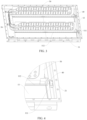
FIG. 1 is a schematic view of an energy storage device provided in embodiments of the disclosure. -
FIG. 2 is a schematic view of an energy storage device provided in other embodiments of the disclosure (with the case being not illustrated). -
FIG. 3 is a schematic view illustrating cooperation of a cooling assembly and a case of an energy storage device provided in embodiments of the disclosure. -
FIG. 4 is a schematic view illustrating cooperation of a heat insulation support, a case, and a cooling assembly of an energy storage device provided in embodiments of the disclosure. -
FIG. 5 is a schematic view illustrating cooperation of a heat insulation support, a case, and a cooling assembly of an energy storage device provided in embodiments of the disclosure. -
FIG. 6 is a schematic view illustrating cooperation of a heat insulation support and a cooling assembly of an energy storage device provided in embodiments of the disclosure. -
FIG. 7 is a schematic view of an insulating plate of an energy storage device provided in embodiments of the disclosure. -
FIG. 8 is a schematic view of a heat insulation support of an energy storage device provided in embodiments of the disclosure. - Explanation of reference signs:
100-energy storage device; 10-case; 11-baseboard; 111-cross beam; 112-longitudinal beam; 1121-positioning hole; 12-side board; 20-battery module; 30-cooling assembly; 40-heat insulation support; 41-fixing segment; 411-fixing groove; 412-positioning protrusion; 413-chamfer; 42-limiting segment; 421-main part; 422-first reinforcing plate; 423-second reinforcing plate; 43-connecting segment; 50-bus plate. - The following will describe embodiments of the present disclosure in detail, and examples of embodiments herein will be illustrated in the accompanying drawings, in which the same or similar reference numerals denote the same or similar components or components having the same or similar functions throughout the context. Embodiments described hereinafter with reference to the accompanying drawings are illustrative and intended for explaining, rather than limiting, the present disclosure.
- The following will describe an
energy storage device 100 and an electric device provided in embodiments of the disclosure with reference fromFIG. 1 to FIG. 8 . - As illustrated in
FIG. 1, FIG. 2 ,FIG. 3, FIG. 4 , andFIG. 5 , theenergy storage device 100 provided in the first aspect of embodiments of the disclosure includes acase 10,multiple battery modules 20, at least one coolingassembly 30, and at least oneheat insulation support 40. - The
multiple battery modules 20 are arranged in thecase 10. Themultiple battery modules 20 are arranged successively in a width direction of thecase 10. The at least one coolingassembly 30 is arranged between themultiple battery modules 20 and each is located at a side of thebattery module 20. Two sides of the coolingassembly 30 may cool twoadjacent battery modules 20 to increase the cooling efficiency. The at least oneheat insulation support 40 is fixedly connected to thecase 10. Theheat insulation support 40 each defines a fixinggroove 411 configured to fix one of the at least one coolingassembly 30. The coolingassembly 30 may be fixed by theheat insulation support 40, thus increasing stability and reliability of the coolingassembly 30 in thecase 10. Heat exchange between thecase 10 and the coolingassembly 30 may be reduced by theheat insulation support 40, so that heat insulation may be more effective and the loss of cold energy of the coolingassembly 30 may be reduced, which improves cooling efficiency and cooling effect. In addition, temperature in thecase 10 will not be too low, which avoids temperature in certain areas of thebattery modules 20 from getting lower than other areas, thus achieving better evenness of temperature in thebattery modules 20. - According to the
energy storage device 100 in embodiments of the disclosure, by arranging theheat insulation support 40, heat exchange between the coolingassembly 30 and thecase 10 may be reduced while the coolingassembly 30 is fixed. On one hand, cooling effect and cooling efficiency of the coolingassembly 30 may be improved. On the other hand, temperature in certain areas of thecase 10 will be prevented from getting too low, thus avoiding condensation on thecase 10. Therefore, not only the safety may be improved, but also temperature in certain areas ofbattery modules 20 will not be too low, resulting in that temperature in multiple batteries of asingle battery module 20 and temperature inmultiple battery modules 20 may be more even. - As illustrated in
FIG. 3 ,FIG. 5 , andFIG. 7 . Thecase 10 includes abaseboard 11 and aside board 12. Thebaseboard 11 has across beam 111 and alongitudinal beam 112 perpendicular to thecross beam 111. Thelongitudinal beam 112 is parallel to a length direction of thebattery modules 20, and thecross beam 111 is parallel to a width direction of thebattery modules 20. Thebaseboard 11 and theside board 12 cooperatively form thecase 10. The at least oneheat insulation support 40 is arranged on thecross beam 111 and thelongitudinal beam 112. - Specifically, the
longitudinal beam 112 extends in the length direction of thebattery modules 20, and thecross beam 111 extends in the width direction of thebattery modules 20. Thelongitudinal beam 112 and thecross beam 111 cooperatively define an accommodating space, and abattery module 20 may be arranged in each accommodating space. Thebattery modules 20 are fixed to thecross beam 111 and thelongitudinal beam 112, and the at least oneheat insulation support 40 is disposed on thecross beam 111 and thelongitudinal beam 112. Fixing stability of the coolingassembly 30 on theheat insulation support 40 may be improved by improving fixing stability of theheat insulation 40 in thecase 10. At the same time, the coolingassembly 30 and theside board 12 may be spaced apart to further reduce heat exchange between thecase 10 and the coolingassembly 30. - According to embodiments of the disclosure, the
heat insulation support 40 includes a fixingsegment 41, a limitingsegment 42, and a connectingsegment 43. The fixingsegment 41 is located at one side of thecross beam 111 and is fixed to thelongitudinal beam 112. The fixinggroove 411 is defined on top of the fixingsegment 41. The limitingsegment 42 is located at the other side of thecross beam 111. Two ends of the connectingsegment 43 are connected to the fixingsegment 41 and the limitingsegment 42 respectively, and the connectingsegment 43 is supported by thecross beam 111. - Specifically, as illustrated in
FIG. 4 andFIG. 8 , theheat insulation support 40 includes the connectingsegment 43, the fixingsegment 41, and limitingsegment 42. The fixingsegment 41 and the limitingsegment 42 are located at two ends of the connectingsegment 43. The fixingsegment 41 extends in the length direction of thecase 10. The limitingsegment 42 extends in the width direction of thecase 10. The fixingsegment 41 and the limitingsegment 42 each are fixed to thebaseboard 11 of thecase 10. The fixingsegment 42 abuts against theside board 12 of thecase 10, separating theside board 12 of thecase 10 from the coolingassembly 30. - The projection of the
heat insulation support 40 in a height direction may be T-shaped or cross-shaped, then a three-point support or a four-point support for theheat insulation support 40 in thecase 10 may be realized by the fixingsegment 41 and the limitingsegment 42. The fixing stability and reliability of the coolingassembly 30 on theheat insulation support 40 may be improved by improving fixing stability and reliability of theheat insulation 40 in thecase 10. - While the limiting
segment 42 is fixed on thebaseboard 11, at least part of the limitingsegment 42 extends to theside board 12 of thecase 10 in the length direction of thecase 10, and abuts against theside board 12. - As illustrated in
FIG. 4 andFIG. 5 , the fixingsegment 41 is located at one side of a fixing beam, and the limitingsegment 42 is located at the other side of the fixing beam. - Specifically, the fixing beam is arranged on the
baseboard 11 and extends in the width direction of thecase 10. The fixing beam is separated from theside board 12 in the length direction of thecase 10. Thebattery modules 20 are arranged in thecase 10, and an end of each of thebattery modules 20 is fixed to the fixing beam to increase the fixing stability of thebattery modules 20 in thecase 10. The connectingsegment 43 is constructed as a plate, and extends in the length direction of thecase 10 to cross the fixing beam, i.e. facing the fixing beam in the height direction of thecase 10. The fixingsegment 41 and the limitingsegment 42 are located at two sides of the fixing beam. The fixingsegment 41 and the limitingsegment 42 located at two ends of the fixing beam are connected to thebaseboard 11. Theheat insulation support 40 may be limited by the fixing beam, so as to avoid the movement of theheat insulating support 40 in the length direction of thecase 10, and to improve fixing stability and reliability of theheat insulation support 40 and the coolingassembly 30 in thecase 10. - According to the
energy storage device 100 provided in embodiments of the disclosure, theheat insulation support 40 is arranged. On one hand, theheat insulation support 40 may serve as a triangular support, so that fixing stability and reliability of the coolingassembly 30 in thecase 10 may be increased. On the other hand, heat exchange between theside board 12 and the coolingassembly 30 may be reduced, so that cooling effect and cooling efficiency of the coolingassembly 30 may be improved, and at the same time, temperature in certain areas of thecase 10 will not be too low. Therefore, temperature in thebattery module 20 is ensured to be even, which avoids large temperature difference in thebattery module 20, and improves working stability and the safety of theenergy storage device 100. - It may be noted that, the
heat insulation support 40 is made of insulating material, which reduces heat exchange between theside board 12 and the coolingassembly 30, and at the same time has better insulation performance to meet the requirement of the electrical protection level of theenergy storage device 100. - In embodiments illustrated in
FIG. 3, FIG. 4 , andFIG. 7 , the fixingsegment 41 has apositioning protrusion 412 at bottom of the fixingsegment 41, and thelongitudinal beam 112 defines apositioning hole 1121. - An insulating plate may be arranged between the
baseboard 11 of thecase 10 and thebattery modules 20, and the insulating plate has thelongitudinal beam 112. Thepositioning hole 1121 is defined on the insulating plate. Therefore, insulation between thebattery modules 20 and thebaseboard 11 may be realized, thus improving the safety of theenergy storage device 100. The insulating plate is laid on thebaseboard 11. The fixingsegment 41 may be fixed on thebaseboard 11 through the matching between the positioningprotrusion 412 and thepositioning hole 1121. Through the matching between the positioningprotrusion 412 and thepositioning hole 1121, not only theheat insulation support 40 is fixed stably on the insulating plate, but also a positioning effect can be achieved, which avoids movement of theheat insulation support 40. - The positioning structure provided in embodiments of the present application is not limited thereto. In other embodiments, a
positioning hole 1121 may be defined on a fixingsection 41, and apositioning protrusion 412 may be arranged on the insulating plate or thebaseboard 11 correspondingly. In order to improve assembly convenience, peripheral side surfaces of thepositioning protrusion 412 and/or sidewalls of thepositioning hole 1121 each may be a guiding surface extending obliquely, to improve assembly guide during assembly. - As illustrated in
FIG. 6 andFIG. 8 , in some embodiments, the fixinggroove 411 is defined on top of the fixingsegment 41, and the fixinggroove 411 has openings on one side of the fixinggroove 411 away from the connectingsegment 43 and on top of the fixinggroove 411, for insertion of the coolingassembly 30. - Specifically, two mounting plates are arranged on top of the fixing
segment 41, the two mounting plates define the fixinggroove 411, and the coolingassembly 30 is installed in the fixinggroove 411. By clamping and fixing the coolingassembly 30 at both ends of the coolingassembly 30 with the two mounting plates, not only the coolingassembly 30 may be stably fixed, but also the coolingassembly 30 may be vertically arranged in the height direction. Therefore, vertical limiting of the coolingassembly 30 may be realized, so that the cooling effect of the coolingassembly 30 on thebattery modules 20 on both sides of the coolingassembly 30 is consistent. Temperature inmultiple battery modules 20 may be more even, overheating on certain areas of the battery modules is avoided, and the working stability of theenergy storage device 100 is improved. - The two mounting plates each have one end connected to the connecting
segment 43, and a free end of one mounting plate is spaced apart from a free end of the other mounting plate, so that the top and one side of the fixinggroove 411 are open, which makes the installation of the coolingassembly 30 on theheat insulation support 40 more convenient. - It may be understood that, the thickness of the two mounting plates which define the fixing
groove 411 is consistent with a distance between twoadjacent battery modules 20, so that the gap between twoadjacent battery modules 20 may be consistent and reasonable in size. Then the uniformity of glue-pouring may be ensured, and the thickness of the glue may be more consistent. - Further, the fixing
groove 411 haschamfers 413 at the openings to for assembly guiding, which makes the installation of the coolingassembly 30 on theheat insulation support 40 more convenient. - In some embodiments, two side walls of the fixing
groove 411 located at both sides of the coolingassembly 30 are equal in thickness, that is, two mounting plates are equal in thickness, so that force distribution on two sides of theheat insulation support 40 in the width direction is more even. Therefore, fixing stability may be improved, and the structural strength and the stability of theheat insulation support 40 may also be improved. - As illustrated in
FIG. 8 , according to embodiments of the disclosure, the limitingsegment 42 includes amain part 421, a first reinforcingplate 422, and two second reinforcingplates 423. Themain part 421 is located between thecross beam 111 and theside board 12 of thecase 10. Two ends of themain part 421 abut against thecross beam 111 and theside board 12 respectively. Themain part 421 is perpendicular to the connectingsegment 43. The first reinforcingplate 422 is arranged on themain part 421. The first reinforcing plate is connected to the connectingsegment 43 and coplanar with the connectingsegment 43. The two second reinforcingplates 423 are arranged on two sides of the first reinforcingplate 422 respectively. The two second reinforcingplates 423 each are perpendicular to the first reinforcingplate 422. The two reinforcingplates 423 are arranged symmetrically with respect to the first reinforcingplate 422. - Specifically, the
main part 421 extends in the width direction of thebattery modules 20. A strengthening flange may be arranged on an upper side of themain part 421, and a resisting plate extending toward thebaseboard 11 may be arranged on a lower side of themain part 421, so that themain part 421 may be arranged between thecross beam 111 and theside board 12. One end of the first reinforcingplate 422 is connected to the connectingsegment 43 and extends in the length direction of thebattery modules 20. The two second reinforcingplates 423 are located at two sides of the first reinforcingplate 422, and extends in the width direction of thebattery modules 20. The structural strength of theheat insulation support 40 may be improved, and the fixing stability and reliability of the limitingsegment 42 on thebaseboard 11 may be further improved. - It may be noted that, at least one cooling
assembly 30 each has at least one end in the length direction of thebattery modules 20 fixed in at least one fixinggroove 411 of at least oneheat insulation support 40. Then the coolingassembly 30 may be stably and reliably fixed in thecase 10 by theheat insulation support 40. - Exemplarily, in some embodiments, the
energy storage device 100 includesmultiple cooling assemblies 30, and each coolingassembly 30 is arranged between twoadjacent battery modules 20. Theenergy storage device 100 includes multiple heat insulation supports 40. Each of themultiple cooling assemblies 30 is provided with theheat insulation support 40 on each of two ends of the coolingassembly 30 in the length direction of thebattery modules 20. Two ends the coolingassembly 30 in the length direction of thebattery modules 20 are fixed in the fixinggrooves 411 of the heat insulation supports 40. In other embodiments, as illustrated inFIG. 3 ,FIG. 5, and FIG. 6 , theenergy storage device 100 includesmultiple cooling assemblies 30.Abus plate 50 is arranged on the same end of themultiple cooling assemblies 30 in the length direction of thebattery modules 20. Themultiple cooling assemblies 30 are connected to one another through thebus plate 50. - The
multiple cooling assemblies 30 are arranged opposite to each other in the width direction of thebattery modules 20. In an embodiment in which themultiple cooling assemblies 30 are arranged independently, heat insulation supports 40 are required at two ends of each coolingassembly 30. In an embodiment in which themultiple cooling assemblies 30 are connected through thebus plate 50 at one end on the same side, eachheat insulation support 40 may be arranged only at an end away from thebus plate 50. - It may be understood that, the cooling
assembly 30 is arranged betweenadjacent battery modules 20, and eachbattery module 20 has one side in contact with the coolingassembly 30. Therefore, themultiple battery modules 20 have similar cooling amount, which makes the temperature in themultiple battery modules 20 more even. - According to embodiments of the disclosure, the fixing
segment 41, the connectingsegment 43, and the limitingsegment 42 are integrally formed, which raises manufacture efficiency of theheat insulation support 40, and reduces manufacture cost of theheat insulation support 40. - It may be understood that directional relationship or positional relationship indicated by terms such as "center", "longitudinal", "lateral", "length", "width", "thickness", "on", "under", "front", "back", "left", "right", "vertical", "horizontal", "top", "bottom", "in", "out", "clockwise", "anticlockwise", "axial", "radial", "circumferential", and the like is directional relationship or positional relationship based on accompanying drawings and are only for the convenience of description and simplicity, rather than explicitly or implicitly indicate that apparatuses or components referred to herein must have a certain direction or be configured or operated in a certain direction, which may not be understood as limitation on the disclosure.
- In description of the disclosure, "first feature" and "second feature" may include one or more of the feature.
- In description of the disclosure, "multiple" means two of more than two.
- In description of the disclosure, a first feature being "on" or "under" a second feature referred to herein may refer to a direct contact between the first feature and the second feature, or an indirect contact between the first feature and the second feature via another feature.
- In description of the disclosure, the first feature being "above", "over", and "on" the second feature may be the first feature being right above or obliquely above the second feature, or only refers to the first feature being at a higher horizontal level than the second feature.
- The reference term "an embodiment", "some embodiments", "implementation", "specific implementation", or "some implementations" referred to herein means that a particular feature, structure, material, or characteristic described in conjunction with the embodiment or implementation may be contained in at least one embodiment or implementation of the disclosure. The phrase appearing in various places in the specification does not necessarily refer to the same embodiment or implementation. The particular feature, structure, material, or characteristic described may be properly combined in any one or more embodiments or implementations.
- While embodiments of the disclosure are shown and described, those of ordinary skill in the art may understand that variations, changes, substitutions, and modifications may be made to these embodiments without departing from the principles and purposes of the disclosure, the scope of protection of the disclosure should be stated in the scope of protection of the claims and the equivalents.
Claims (12)
- An energy storage device, comprising:a case (10);a plurality of battery modules (20), wherein the plurality of battery modules are accommodated in the case (10);at least one cooling assembly (30), wherein the at least one cooling assembly is arranged between the plurality of battery modules (20); andat least one heat insulation support (40) fixedly connected to the case (10), wherein the at least one heat insulation support (40) each defines a fixing groove (411) configured to fix one of the at least one cooling assembly (30).
- The energy storage device of claim 1, wherein the case (10) comprises:a baseboard (11), wherein the baseboard (11) has a cross beam (111) and a longitudinal beam (112) perpendicular to the cross beam (111), the longitudinal beam (112) is parallel to a length direction of the plurality of battery modules (20), and the cross beam (111) is parallel to a width direction of the plurality of battery modules (20);a side board (12), wherein the baseboard (11) and the side board (12) cooperatively form the case (10); andwherein the at least one heat insulation support (40) is arranged on the cross beam (111) and the longitudinal beam (112).
- The energy storage device of claim 1, wherein each of the at least one heat insulation support comprises:a fixing segment (41) located at one side of the cross beam (111) and fixed to the longitudinal beam (112), wherein the fixing groove (411) is defined on top of the fixing segment (41);a limiting segment (42) located at the other side of the cross beam (111); anda connecting segment (43), wherein two ends of the connecting segment (43) are connected to the fixing segment (41) and the limiting segment (42) respectively, and the connecting segment (43) is supported by the cross beam (111).
- The energy storage device of claim 3, wherein the fixing segment (41) has a positioning protrusion (412) at bottom of the fixing segment (41), the longitudinal beam (112) defines a positioning hole (1121), and the positioning protrusion (412) is inserted into the positioning hole (1121).
- The energy storage device of claim 3, wherein the fixing groove (411) has openings on one side of the fixing groove (411) away from the connecting segment (43) and on top of the fixing groove (411), for insertion of a cooling assembly (30).
- The energy storage device of any one of claims 3 to 5, wherein the fixing groove (411) has chamfers (413) at the openings.
- The energy storage device of claim 3, wherein groove walls of the fixing groove (411) on two sides of the cooling assembly (30) are equal in thickness.
- The energy storage device of claim 3, wherein the limiting segment (42) comprises:a main part (421) located between the cross beam (111) and the side board (12) of the case (10), wherein two ends of the main part (421) abut against the cross beam (111) and the side board (12) respectively, and the main part (421) is perpendicular to the connecting segment (43);a first reinforcing plate (422) arranged on the main part (421), wherein the first reinforcing plate (422) is connected to the connecting segment (43) and coplanar with the connecting segment (43); andtwo second reinforcing plates (423) arranged on two sides of the first reinforcing plate (422) respectively, wherein the two second reinforcing plates (423) each are perpendicular to the first reinforcing plate (422), and the two reinforcing plates (423) are arranged symmetrically with respect to the first reinforcing plate (422).
- The energy storage device of claim 1, wherein the at least one cooling assembly (30) each has at least one end in the length direction of the battery modules (20) fixed in at least one fixing groove (411) of at least one heat insulation support (40).
- The energy storage device of claim 9, wherein the energy storage device comprises a plurality of cooling assemblies (30), each of the plurality of cooling assemblies is arranged between two adjacent battery modules (20), the energy storage device comprises a plurality of heat insulation supports (40), each of the plurality of cooling assemblies (30) is provided with a heat insulation support (40) on each of two ends of said each of the plurality of cooling assemblies (30) in the length direction of the battery modules (20), and two ends of each of the plurality of cooling assemblies (30) in the length direction of the battery modules (20) are fixed in fixing grooves (411) of heat insulation supports (40).
- The energy storage device of claim 9, wherein the energy storage device comprises a plurality of cooling assemblies (30), a bus plate (50) is arranged on the same end of the plurality of cooling assemblies (30) in the length direction of the battery modules (20), and the plurality of cooling assemblies (30) are connected to one another through the bus plate (50).
- The energy storage device of claim 3, wherein the fixing segment (41), the connecting segment (43), and the limiting segment (42) are integrally formed.
Applications Claiming Priority (2)
| Application Number | Priority Date | Filing Date | Title |
|---|---|---|---|
| CN202211438939.7A CN115692933B (en) | 2022-11-17 | 2022-11-17 | Energy storage device |
| PCT/CN2022/141103 WO2024103487A1 (en) | 2022-11-17 | 2022-12-22 | Energy storage device |
Publications (3)
| Publication Number | Publication Date |
|---|---|
| EP4395005A1 true EP4395005A1 (en) | 2024-07-03 |
| EP4395005A4 EP4395005A4 (en) | 2025-03-19 |
| EP4395005B1 EP4395005B1 (en) | 2025-12-10 |
Family
ID=88586113
Family Applications (1)
| Application Number | Title | Priority Date | Filing Date |
|---|---|---|---|
| EP22932489.2A Active EP4395005B1 (en) | 2022-11-17 | 2022-12-22 | Energy storage device |
Country Status (8)
| Country | Link |
|---|---|
| US (1) | US20240170768A1 (en) |
| EP (1) | EP4395005B1 (en) |
| JP (1) | JP7695499B2 (en) |
| KR (1) | KR102956113B1 (en) |
| AU (1) | AU2022447730B9 (en) |
| CA (1) | CA3213907A1 (en) |
| IL (1) | IL307325A (en) |
| ZA (1) | ZA202309145B (en) |
Family Cites Families (13)
| Publication number | Priority date | Publication date | Assignee | Title |
|---|---|---|---|---|
| KR19990038740U (en) * | 1998-03-31 | 1999-10-25 | 전주범 | Heat dissipation device for heat generating electronic parts of electronic products |
| JP5583041B2 (en) | 2011-02-04 | 2014-09-03 | 三菱重工業株式会社 | Battery module |
| CN205900748U (en) | 2016-07-21 | 2017-01-18 | 北京新能源汽车股份有限公司 | Power battery system and automobile with same |
| KR102036085B1 (en) | 2016-12-23 | 2019-10-24 | 에스케이이노베이션 주식회사 | Secondary battery module |
| JP2018116813A (en) | 2017-01-17 | 2018-07-26 | 株式会社東芝 | Battery module and battery device |
| CN207381452U (en) * | 2017-10-31 | 2018-05-18 | 宁德时代新能源科技股份有限公司 | Battery pack |
| JP6922683B2 (en) | 2017-11-17 | 2021-08-18 | トヨタ自動車株式会社 | Battery pack, battery pack manufacturing method and intervening members |
| CN110048184A (en) * | 2019-03-25 | 2019-07-23 | 力神动力电池系统有限公司 | A kind of rectangular cell water-cooled module for electric vehicle |
| DE102020121498A1 (en) * | 2020-05-19 | 2021-11-25 | Man Truck & Bus Se | Energy storage device with a battery cell module and a cooling device, preferably for an at least partially electrically driven vehicle, and method for producing the energy storage device |
| CN111564589B (en) | 2020-05-29 | 2022-05-27 | 蜂巢能源科技有限公司 | Battery pack |
| KR20220001988A (en) * | 2020-06-30 | 2022-01-06 | 주식회사 엘지에너지솔루션 | Battery Module, Battery Pack, Vehicle, and Method For Manufacturing Battery Module |
| JP7651346B2 (en) | 2021-03-29 | 2025-03-26 | イビデン株式会社 | Heat transfer suppression sheet for battery pack and battery pack |
| CN215771323U (en) * | 2021-06-17 | 2022-02-08 | 比亚迪股份有限公司 | Battery pack and vehicle |
-
2022
- 2022-12-22 AU AU2022447730A patent/AU2022447730B9/en active Active
- 2022-12-22 JP JP2023560387A patent/JP7695499B2/en active Active
- 2022-12-22 EP EP22932489.2A patent/EP4395005B1/en active Active
- 2022-12-22 KR KR1020237033480A patent/KR102956113B1/en active Active
- 2022-12-22 CA CA3213907A patent/CA3213907A1/en active Pending
-
2023
- 2023-09-27 IL IL307325A patent/IL307325A/en unknown
- 2023-09-28 US US18/374,514 patent/US20240170768A1/en active Pending
- 2023-09-28 ZA ZA2023/09145A patent/ZA202309145B/en unknown
Also Published As
| Publication number | Publication date |
|---|---|
| CA3213907A1 (en) | 2024-05-17 |
| EP4395005A4 (en) | 2025-03-19 |
| JP7695499B2 (en) | 2025-06-19 |
| JP2024544096A (en) | 2024-11-28 |
| AU2022447730B9 (en) | 2025-03-27 |
| KR20240073811A (en) | 2024-05-27 |
| EP4395005B1 (en) | 2025-12-10 |
| KR102956113B1 (en) | 2026-04-22 |
| US20240170768A1 (en) | 2024-05-23 |
| IL307325A (en) | 2023-11-01 |
| ZA202309145B (en) | 2024-11-27 |
| AU2022447730A1 (en) | 2024-06-06 |
| AU2022447730B2 (en) | 2025-01-23 |
Similar Documents
| Publication | Publication Date | Title |
|---|---|---|
| EP4546548A1 (en) | Battery pack | |
| EP4685957A1 (en) | Battery pack housing, battery pack, and electric device | |
| US20240170768A1 (en) | Energy storage device | |
| HK40107461A (en) | Energy storage device | |
| CN218569141U (en) | Module support and power battery module | |
| CN217788530U (en) | Battery package liquid cooling subassembly | |
| WO2025113159A1 (en) | Cooling tube, battery assembly, and electrical apparatus | |
| TWI871030B (en) | Energy storage device | |
| CN219553803U (en) | Side-placed module and battery pack | |
| CN114759293B (en) | Cell mounting bracket and battery module having it | |
| CN217822993U (en) | Battery and battery device | |
| CN218896782U (en) | Battery cell | |
| CN218182402U (en) | Battery pack and energy storage equipment | |
| CN115472956A (en) | A cooling structure suitable for lying batteries and battery pack thereof | |
| CN223321367U (en) | Photo frames and modules | |
| CN223638491U (en) | Battery packs and electrical equipment | |
| EP4560787A1 (en) | Battery module and vehicle | |
| CN222775500U (en) | Battery module and battery system | |
| CN218783168U (en) | Trays, splicing cell modules and battery assemblies | |
| CN218070024U (en) | Battery module and battery device with same | |
| CN114824637A (en) | Battery box body assembly and battery module | |
| US20250158237A1 (en) | Battery collection and connection assembly, battery module and battery pack | |
| CN218498260U (en) | Battery pack and electric device | |
| CN222282108U (en) | Battery module and battery pack | |
| CN219350547U (en) | Battery device |
Legal Events
| Date | Code | Title | Description |
|---|---|---|---|
| STAA | Information on the status of an ep patent application or granted ep patent |
Free format text: STATUS: UNKNOWN |
|
| STAA | Information on the status of an ep patent application or granted ep patent |
Free format text: STATUS: THE INTERNATIONAL PUBLICATION HAS BEEN MADE |
|
| PUAI | Public reference made under article 153(3) epc to a published international application that has entered the european phase |
Free format text: ORIGINAL CODE: 0009012 |
|
| STAA | Information on the status of an ep patent application or granted ep patent |
Free format text: STATUS: REQUEST FOR EXAMINATION WAS MADE |
|
| 17P | Request for examination filed |
Effective date: 20230927 |
|
| AK | Designated contracting states |
Kind code of ref document: A1 Designated state(s): AL AT BE BG CH CY CZ DE DK EE ES FI FR GB GR HR HU IE IS IT LI LT LU LV MC ME MK MT NL NO PL PT RO RS SE SI SK SM TR |
|
| REG | Reference to a national code |
Ref country code: HK Ref legal event code: DE Ref document number: 40107461 Country of ref document: HK |
|
| A4 | Supplementary search report drawn up and despatched |
Effective date: 20250214 |
|
| RIC1 | Information provided on ipc code assigned before grant |
Ipc: H01M 10/658 20140101ALI20250210BHEP Ipc: H01M 10/6557 20140101ALI20250210BHEP Ipc: H01M 10/6556 20140101ALI20250210BHEP Ipc: H01M 10/617 20140101ALI20250210BHEP Ipc: H01M 10/613 20140101AFI20250210BHEP |
|
| RAP1 | Party data changed (applicant data changed or rights of an application transferred) |
Owner name: HITHIUM TECH HK LIMITED |
|
| GRAP | Despatch of communication of intention to grant a patent |
Free format text: ORIGINAL CODE: EPIDOSNIGR1 |
|
| STAA | Information on the status of an ep patent application or granted ep patent |
Free format text: STATUS: GRANT OF PATENT IS INTENDED |
|
| DAV | Request for validation of the european patent (deleted) | ||
| DAX | Request for extension of the european patent (deleted) | ||
| INTG | Intention to grant announced |
Effective date: 20250723 |
|
| GRAS | Grant fee paid |
Free format text: ORIGINAL CODE: EPIDOSNIGR3 |
|
| GRAA | (expected) grant |
Free format text: ORIGINAL CODE: 0009210 |
|
| STAA | Information on the status of an ep patent application or granted ep patent |
Free format text: STATUS: THE PATENT HAS BEEN GRANTED |
|
| AK | Designated contracting states |
Kind code of ref document: B1 Designated state(s): AL AT BE BG CH CY CZ DE DK EE ES FI FR GB GR HR HU IE IS IT LI LT LU LV MC ME MK MT NL NO PL PT RO RS SE SI SK SM TR |
|
| REG | Reference to a national code |
Ref country code: CH Ref legal event code: F10 Free format text: ST27 STATUS EVENT CODE: U-0-0-F10-F00 (AS PROVIDED BY THE NATIONAL OFFICE) Effective date: 20251210 Ref country code: GB Ref legal event code: FG4D |
|
| REG | Reference to a national code |
Ref country code: DE Ref legal event code: R096 Ref document number: 602022026820 Country of ref document: DE |
|
| REG | Reference to a national code |
Ref country code: IE Ref legal event code: FG4D |
|
| PGFP | Annual fee paid to national office [announced via postgrant information from national office to epo] |
Ref country code: AT Payment date: 20260113 Year of fee payment: 4 |
|
| PGFP | Annual fee paid to national office [announced via postgrant information from national office to epo] |
Ref country code: FR Payment date: 20251218 Year of fee payment: 4 |
|
| PG25 | Lapsed in a contracting state [announced via postgrant information from national office to epo] |
Ref country code: ES Free format text: LAPSE BECAUSE OF FAILURE TO SUBMIT A TRANSLATION OF THE DESCRIPTION OR TO PAY THE FEE WITHIN THE PRESCRIBED TIME-LIMIT Effective date: 20251210 |
|
| REG | Reference to a national code |
Ref country code: LT Ref legal event code: MG9D |
|
| PG25 | Lapsed in a contracting state [announced via postgrant information from national office to epo] |
Ref country code: NO Free format text: LAPSE BECAUSE OF FAILURE TO SUBMIT A TRANSLATION OF THE DESCRIPTION OR TO PAY THE FEE WITHIN THE PRESCRIBED TIME-LIMIT Effective date: 20260310 |
|
| PGFP | Annual fee paid to national office [announced via postgrant information from national office to epo] |
Ref country code: DE Payment date: 20251222 Year of fee payment: 4 |
|
| PG25 | Lapsed in a contracting state [announced via postgrant information from national office to epo] |
Ref country code: FI Free format text: LAPSE BECAUSE OF FAILURE TO SUBMIT A TRANSLATION OF THE DESCRIPTION OR TO PAY THE FEE WITHIN THE PRESCRIBED TIME-LIMIT Effective date: 20251210 Ref country code: HR Free format text: LAPSE BECAUSE OF FAILURE TO SUBMIT A TRANSLATION OF THE DESCRIPTION OR TO PAY THE FEE WITHIN THE PRESCRIBED TIME-LIMIT Effective date: 20251210 |
|
| REG | Reference to a national code |
Ref country code: NL Ref legal event code: MP Effective date: 20251210 |
|
| PG25 | Lapsed in a contracting state [announced via postgrant information from national office to epo] |
Ref country code: RS Free format text: LAPSE BECAUSE OF FAILURE TO SUBMIT A TRANSLATION OF THE DESCRIPTION OR TO PAY THE FEE WITHIN THE PRESCRIBED TIME-LIMIT Effective date: 20260310 |
|
| PG25 | Lapsed in a contracting state [announced via postgrant information from national office to epo] |
Ref country code: LV Free format text: LAPSE BECAUSE OF FAILURE TO SUBMIT A TRANSLATION OF THE DESCRIPTION OR TO PAY THE FEE WITHIN THE PRESCRIBED TIME-LIMIT Effective date: 20251210 |
|
| PG25 | Lapsed in a contracting state [announced via postgrant information from national office to epo] |
Ref country code: BG Free format text: LAPSE BECAUSE OF FAILURE TO SUBMIT A TRANSLATION OF THE DESCRIPTION OR TO PAY THE FEE WITHIN THE PRESCRIBED TIME-LIMIT Effective date: 20251210 |