EP4395000A1 - Battery, method and apparatus for manufacturing same, and electrical device - Google Patents
Battery, method and apparatus for manufacturing same, and electrical device Download PDFInfo
- Publication number
- EP4395000A1 EP4395000A1 EP21958621.1A EP21958621A EP4395000A1 EP 4395000 A1 EP4395000 A1 EP 4395000A1 EP 21958621 A EP21958621 A EP 21958621A EP 4395000 A1 EP4395000 A1 EP 4395000A1
- Authority
- EP
- European Patent Office
- Prior art keywords
- battery
- sampling
- lead
- electrode terminal
- out portion
- Prior art date
- Legal status (The legal status is an assumption and is not a legal conclusion. Google has not performed a legal analysis and makes no representation as to the accuracy of the status listed.)
- Pending
Links
Images





Classifications
-
- H—ELECTRICITY
- H01—ELECTRIC ELEMENTS
- H01M—PROCESSES OR MEANS, e.g. BATTERIES, FOR THE DIRECT CONVERSION OF CHEMICAL ENERGY INTO ELECTRICAL ENERGY
- H01M50/00—Constructional details or processes of manufacture of the non-active parts of electrochemical cells other than fuel cells, e.g. hybrid cells
- H01M50/20—Mountings; Secondary casings or frames; Racks, modules or packs; Suspension devices; Shock absorbers; Transport or carrying devices; Holders
- H01M50/204—Racks, modules or packs for multiple batteries or multiple cells
-
- H—ELECTRICITY
- H01—ELECTRIC ELEMENTS
- H01M—PROCESSES OR MEANS, e.g. BATTERIES, FOR THE DIRECT CONVERSION OF CHEMICAL ENERGY INTO ELECTRICAL ENERGY
- H01M50/00—Constructional details or processes of manufacture of the non-active parts of electrochemical cells other than fuel cells, e.g. hybrid cells
- H01M50/50—Current conducting connections for cells or batteries
- H01M50/569—Constructional details of current conducting connections for detecting conditions inside cells or batteries, e.g. details of voltage sensing terminals
-
- H—ELECTRICITY
- H01—ELECTRIC ELEMENTS
- H01M—PROCESSES OR MEANS, e.g. BATTERIES, FOR THE DIRECT CONVERSION OF CHEMICAL ENERGY INTO ELECTRICAL ENERGY
- H01M10/00—Secondary cells; Manufacture thereof
- H01M10/42—Methods or arrangements for servicing or maintenance of secondary cells or secondary half-cells
- H01M10/48—Accumulators combined with arrangements for measuring, testing or indicating the condition of cells, e.g. the level or density of the electrolyte
-
- H—ELECTRICITY
- H01—ELECTRIC ELEMENTS
- H01M—PROCESSES OR MEANS, e.g. BATTERIES, FOR THE DIRECT CONVERSION OF CHEMICAL ENERGY INTO ELECTRICAL ENERGY
- H01M10/00—Secondary cells; Manufacture thereof
- H01M10/42—Methods or arrangements for servicing or maintenance of secondary cells or secondary half-cells
- H01M10/48—Accumulators combined with arrangements for measuring, testing or indicating the condition of cells, e.g. the level or density of the electrolyte
- H01M10/482—Accumulators combined with arrangements for measuring, testing or indicating the condition of cells, e.g. the level or density of the electrolyte for several batteries or cells simultaneously or sequentially
-
- H—ELECTRICITY
- H01—ELECTRIC ELEMENTS
- H01M—PROCESSES OR MEANS, e.g. BATTERIES, FOR THE DIRECT CONVERSION OF CHEMICAL ENERGY INTO ELECTRICAL ENERGY
- H01M50/00—Constructional details or processes of manufacture of the non-active parts of electrochemical cells other than fuel cells, e.g. hybrid cells
- H01M50/20—Mountings; Secondary casings or frames; Racks, modules or packs; Suspension devices; Shock absorbers; Transport or carrying devices; Holders
- H01M50/204—Racks, modules or packs for multiple batteries or multiple cells
- H01M50/207—Racks, modules or packs for multiple batteries or multiple cells characterised by their shape
- H01M50/209—Racks, modules or packs for multiple batteries or multiple cells characterised by their shape adapted for prismatic or rectangular cells
-
- H—ELECTRICITY
- H01—ELECTRIC ELEMENTS
- H01M—PROCESSES OR MEANS, e.g. BATTERIES, FOR THE DIRECT CONVERSION OF CHEMICAL ENERGY INTO ELECTRICAL ENERGY
- H01M50/00—Constructional details or processes of manufacture of the non-active parts of electrochemical cells other than fuel cells, e.g. hybrid cells
- H01M50/20—Mountings; Secondary casings or frames; Racks, modules or packs; Suspension devices; Shock absorbers; Transport or carrying devices; Holders
- H01M50/204—Racks, modules or packs for multiple batteries or multiple cells
- H01M50/207—Racks, modules or packs for multiple batteries or multiple cells characterised by their shape
- H01M50/213—Racks, modules or packs for multiple batteries or multiple cells characterised by their shape adapted for cells having curved cross-section, e.g. round or elliptic
-
- H—ELECTRICITY
- H01—ELECTRIC ELEMENTS
- H01M—PROCESSES OR MEANS, e.g. BATTERIES, FOR THE DIRECT CONVERSION OF CHEMICAL ENERGY INTO ELECTRICAL ENERGY
- H01M50/00—Constructional details or processes of manufacture of the non-active parts of electrochemical cells other than fuel cells, e.g. hybrid cells
- H01M50/20—Mountings; Secondary casings or frames; Racks, modules or packs; Suspension devices; Shock absorbers; Transport or carrying devices; Holders
- H01M50/244—Secondary casings; Racks; Suspension devices; Carrying devices; Holders characterised by their mounting method
-
- H—ELECTRICITY
- H01—ELECTRIC ELEMENTS
- H01M—PROCESSES OR MEANS, e.g. BATTERIES, FOR THE DIRECT CONVERSION OF CHEMICAL ENERGY INTO ELECTRICAL ENERGY
- H01M50/00—Constructional details or processes of manufacture of the non-active parts of electrochemical cells other than fuel cells, e.g. hybrid cells
- H01M50/50—Current conducting connections for cells or batteries
- H01M50/502—Interconnectors for connecting terminals of adjacent batteries; Interconnectors for connecting cells outside a battery casing
- H01M50/503—Interconnectors for connecting terminals of adjacent batteries; Interconnectors for connecting cells outside a battery casing characterised by the shape of the interconnectors
-
- H—ELECTRICITY
- H01—ELECTRIC ELEMENTS
- H01M—PROCESSES OR MEANS, e.g. BATTERIES, FOR THE DIRECT CONVERSION OF CHEMICAL ENERGY INTO ELECTRICAL ENERGY
- H01M50/00—Constructional details or processes of manufacture of the non-active parts of electrochemical cells other than fuel cells, e.g. hybrid cells
- H01M50/50—Current conducting connections for cells or batteries
- H01M50/502—Interconnectors for connecting terminals of adjacent batteries; Interconnectors for connecting cells outside a battery casing
- H01M50/507—Interconnectors for connecting terminals of adjacent batteries; Interconnectors for connecting cells outside a battery casing comprising an arrangement of two or more busbars within a container structure, e.g. busbar modules
-
- H—ELECTRICITY
- H01—ELECTRIC ELEMENTS
- H01M—PROCESSES OR MEANS, e.g. BATTERIES, FOR THE DIRECT CONVERSION OF CHEMICAL ENERGY INTO ELECTRICAL ENERGY
- H01M2220/00—Batteries for particular applications
- H01M2220/20—Batteries in motive systems, e.g. vehicle, ship, plane
-
- Y—GENERAL TAGGING OF NEW TECHNOLOGICAL DEVELOPMENTS; GENERAL TAGGING OF CROSS-SECTIONAL TECHNOLOGIES SPANNING OVER SEVERAL SECTIONS OF THE IPC; TECHNICAL SUBJECTS COVERED BY FORMER USPC CROSS-REFERENCE ART COLLECTIONS [XRACs] AND DIGESTS
- Y02—TECHNOLOGIES OR APPLICATIONS FOR MITIGATION OR ADAPTATION AGAINST CLIMATE CHANGE
- Y02E—REDUCTION OF GREENHOUSE GAS [GHG] EMISSIONS, RELATED TO ENERGY GENERATION, TRANSMISSION OR DISTRIBUTION
- Y02E60/00—Enabling technologies; Technologies with a potential or indirect contribution to GHG emissions mitigation
- Y02E60/10—Energy storage using batteries
Definitions
- lithium-ion batteries have been widely used in electric vehicles.
- This application is intended to improve operating reliability of batteries.
- This embodiment can make the sampling member not extend beyond the outer side surface of the battery cell in the third direction on the basis of increasing the extension length of the second end of the lead-out portion, so that arrangement of the adjacent battery cells is not affected. This can minimize the size occupied by a sampling function related structure in the third direction, thus improving the energy density of the battery.
- the first end of the lead-out portion is connected to one end of the sampling portion in the second direction, so that an operation space can be reserved for the connection between the sampling portion and the electrode terminal.
- the second end of the lead-out portion extends along a direction leaving the sampling portion, so that an extension direction of the second end of the lead-out portion is independent of the operation region where the sampling portion and the electrode terminal are connected. This facilitates the connection between the second end of the lead-out portion and the signal output component, as well as the connection between the sampling portion and the electrode terminal, thus facilitating assembly and improving assembly performance.
- such design is also convenient for forming the sampling member by cutting and bending the whole thin plate, with no need to connect the sampling portion and the lead-out portion additionally, thus reducing the manufacturing difficulty of the sampling member.
- the first end of the lead-out portion is connected to a position of the sampling portion in a center of the battery cell along the first direction, and the second end of the lead-out portion extends to a position between the adjacent battery units along the first direction.
- the plurality of sampling portions are electrically connected, and only one lead-out portion is needed to implement lead-out of electrical signals, thus simplifying the structure and reducing the materials used for the sampling member.
- most of the lead-out portion can be integrally fastened in the mounting part by injection molding and encapsulation, and the second end of the lead-out portion does not need to be fastened to the mounting part, so there is no need to correspondingly arrange one lead-out portion for each sampling portion, and only one lead-out portion is needed for one sampling member.
- the sampling member further includes a connecting portion, where the connecting portion is connected between adjacent sampling portions, the first end of the lead-out portion is connected at a position of the connecting portion between adjacent battery units, and the second end of the lead-out portion extends in the third direction, the third direction being perpendicular to the first direction and the second direction.
- adjacent sampling portions are electrically connected through the connecting portion, so that the plurality of sampling portions can be connected into a whole.
- the first end of the lead-out portion is directly connected to the position of the connecting portion between the battery units, so that the second end of the lead-out portion can reach the position between the adjacent battery units when the second end of the lead-out portion directly extends in the third direction, thus simplifying the structure of the lead-out portion.
- two ends of the connecting portion are respectively connected to the positions of adjacent sampling portions close to the lead-out portion in the third direction.
- This embodiment is beneficial to ensure the relative positions of the sampling portions, so that the sampling portions are aligned with the electrode terminals for connection, preventing the electrode terminals from being subjected to lateral pulling force during mounting of the sampling portions.
- the connecting portion can be encapsulated and molded in the mounting part to implement more reliable fixation between the sampling member and the mounting part, so as to reduce the acting force on the lead-out portion.
- this structure can also reduce the overall length of the lead-out portion, which is beneficial to improve the rigidity of the lead-out portion and prevent the lead-out portion from being deformed.
- the connecting portion is provided with a deformable section configured to allow dislocation of the adjacent sampling portions.
- the vibration or impact when the battery is subjected to vibration or impact, the vibration or impact can be absorbed through the deformation of the deformable section, allowing for a small amount of dislocation of the adjacent sampling portions, preventing the adjacent sampling portions from being disconnected after long-term operation, and improving the sampling reliability of the battery cells.
- a mounting part is further included, which is mounted on the battery cell and connected to the sampling member.
- An accommodating groove is provided on the mounting part and is configured to accommodate the second end of the lead-out portion, and the accommodating groove is provided on a surface of the mounting part far away from the battery unit in the third direction and is located at a position between adjacent battery units in the first direction; where the third direction is perpendicular to the first direction and the second direction.
- the mounting part is provided to facilitate the connection of the sampling member and position the sampling member relative to the battery cell, thus ensuring the position accuracy of the mounted sampling member and preventing the sampling member from shaking.
- the accommodating groove is provided on the mounting part to accommodate the second end of the lead-out portion, which can protect the second end of the lead-out portion, prevent the second end of the lead-out portion from being deformed due to collision during assembly, and ensure the insulation of the second end of the lead-out portion.
- the mounting part is provided with an opening, the opening is disposed opposite the electrode terminal in the first direction, and the opening is configured to form a channel for connecting the sampling portion and the electrode terminal.
- the electrode terminals of at least one pair of adjacent battery cells in the battery unit are interconnected in the second direction, and the sampling portion is electrically connected to the two electrode terminals.
- a manufacturing apparatus of a battery including:
- a plurality of means more than two (inclusive).
- a plurality of groups means more than two (inclusive) groups
- a plurality of pieces means more than two (inclusive) pieces.
- the inventors have found that the design of the battery requires consideration of many design factors, for example, performance parameters such as energy density, cycle life, discharge capacity, and charge and discharge rate, as well as safety of the battery.
- the battery cell 1 may be, for example, a lithium-ion secondary battery, a lithium-ion primary battery, a lithium-sulfur battery, a sodium-ion battery, a magnesium-ion battery, or the like.
- the basic structures of the battery 100 and the battery cell 1 have been described. The following will describe the structures related to the sampling function in the battery 100.
- a plurality of battery units 10 are arranged side by side along a first direction x, where each battery unit 10 includes at least two battery cells 1 arranged along a second direction y, the battery cell 1 includes a body portion 11, a gap is formed between the body portions 11 of at least one pair of adjacent battery cells 1 in the battery unit 10, at least one battery cell 1 in the adjacent battery cells 1 includes an electrode terminal 12 protruding from the body portion 11 along the second direction y, and the electrode terminal 12 is located in the gap and configured to be electrically connected to the other battery cell 1; where the second direction y is perpendicular to the first direction x.
- the sampling member 2 is electrically connected to the electrode terminal 12 of only one battery unit 10, only voltage of the battery cells 1 in one battery unit 10 can be collected. If one sampling member 2 is electrically connected to the electrode terminals 12 of a plurality of battery units 10 simultaneously, the plurality of battery units 10 can be connected in parallel through the sampling member 2, thereby implementing the series-parallel connection of a plurality of battery cells 1 in the battery 100.
- the electrical signal obtained by the sampling member 2 is the potential at the electrode terminal 12 connected to the sampling member 2.
- the voltages at two ends of one or more battery cells 1 can be calculated by obtaining the potentials of different electrode terminals 12.
- the sampling member 2 can be made of a conductive material such as metal.
- the second end of the lead-out portion 22 is led out from between the adjacent battery units 10, which can prevent occupation of extra space, increase the extension length of the second end of the lead-out portion 22, facilitate the electrical connection with the signal output component, and improve the reliability of the electrical connection.
- This allows for accurate collection of the electrical signals of the battery cells 1 and reliable monitoring of the battery cells 1 to discover abnormal situations, so as to facilitate timely control and handling, and improve the operating reliability of the battery 100.
- the welding area can be increased, so as to prevent virtual contact or disconnection of the welding point caused by long-term vibration or impact, thus improving the welding reliability.
- the lead-out portion 22 does not extend beyond an outer side surface of the battery cell 1 in a third direction z, where the third direction z is perpendicular to the first direction x and the second direction y.
- the second end of the lead-out portion 22 extends in a gap between adjacent battery cells 1 in the first direction x.
- This embodiment can make the sampling member 2 not extend beyond the outer side surface of the battery cell 1 in the third direction z on the basis of increasing the extension length of the second end of the lead-out portion 22, so that arrangement of the adjacent battery cells 1 is not affected. This can minimize the size occupied by a sampling function related structure in the third direction z, thus improving the energy density of the battery 100.
- the second end of the lead-out portion 22 extends along a direction leaving the electrode terminal 12.
- the second end of the lead-out portion 22 extends in the second direction y, that is, parallel to the side wall of the body portion 11, which is convenient for increasing the extension length of the second end of the lead-out portion 22, increasing the size of the lead-out portion 22 along the first direction x, and preventing the second end of the lead-out portion 22 from affecting the side wall of the body portion 11.
- the first end of the lead-out portion 22 is close to the side end of the sampling portion 21 in the second direction y, and in the second direction y, the second end of the lead-out portion 22 extends along a direction leaving the sampling portion 21.
- the first end of the lead-out portion 22 is connected to one end of the sampling portion 21 in the second direction y, so that an operation space can be reserved for the connection between the sampling portion 21 and the electrode terminal 12.
- the second end of the lead-out portion 22 extends along a direction leaving the sampling portion 21, so that an extension direction of the second end of the lead-out portion 22 is independent of the operation region where the sampling portion 21 and the electrode terminal 12 are connected. This facilitates the connection between the second end of the lead-out portion 22 and the signal output component, as well as the connection between the sampling portion 21 and the electrode terminal 12, thus facilitating assembly and improving assembly performance.
- such design is also convenient for forming the sampling member 2 by cutting and bending the whole thin plate, with no need to connect the sampling portion 21 and the lead-out portion 22 additionally, thus reducing the manufacturing difficulty of the sampling member 2.
- the first end of the lead-out portion 22 is connected to a position of the sampling portion 21 in a center of the battery cell 1 along the first direction x, and the second end of the lead-out portion 22 extends to a position between the adjacent battery units 10 along the first direction x.
- the lead-out portion 22 may include a connecting section 223 and an extension section 222, where a first end of the connecting section 223 is connected to the sampling portion 21 and in the third direction z, extends in a direction leaving the sampling portion 21, the first end of the connecting section 223 serves as the first end of the lead-out portion 22, and an end of the extension section 222 is connected to a second end of the connecting section 223 and extends in the first direction x.
- An L-shaped structure is formed between the connecting section 223 and the extension section 222, which helps improve the rigidity of the lead-out portion 22, preventing the lead-out portion 22 from being deformed after assembly and mounting.
- the sampling member 2 includes a plurality of sampling portions 21 spaced apart along the first direction x, and the adjacent sampling portions 21 are connected to each other.
- the whole sampling member 2 is made of a conductive material, and the adjacent sampling portions 21 are electrically connected, thus implementing parallel connection of a plurality of battery cells 1 arranged side by side in a plurality of battery units 10.
- the sampling member 2 may further include a connecting portion 23, and the connecting portion 23 is connected between the adjacent sampling portions 21 to implement electrical connection between the adjacent sampling portions 21.
- the sampling member 2 may simultaneously collect electrical signals from the plurality of battery cells 1 arranged in the first direction x, and the electrode terminals 12 of the plurality of battery cells 1 that are electrically connected to a plurality of sampling portions 21 of one sampling member 2 have an equal potential.
- the electrode terminals 12 of the plurality of battery cells 1 that are electrically connected to a plurality of sampling portions 21 of one sampling member 2 can be designed to have an equal potential, thus achieving voltage balance of the battery cells 1 and improving consistency of detection parameters of the plurality of battery cells 1.
- the plurality of sampling portions 21 share one lead-out portion 22.
- the plurality of sampling portions 21 are electrically connected, and only one lead-out portion 22 is needed to implement lead-out of electrical signals, thus simplifying the structure and reducing the materials used for the sampling member 2.
- most of the lead-out portion 22 can be integrally fastened in the mounting part 3 by injection molding and encapsulation, and the second end of the lead-out portion 22 does not need to be fastened to the mounting part 3, so there is no need to correspondingly arrange one lead-out portion 22 for each sampling portion 21, and only one lead-out portion 22 is needed for one sampling member 2.
- the sampling portion 21 is of a partially annular structure, and the two ends of the connecting portion 23 are connected to the respective adjacent end portions of the adjacent sampling portions 21.
- the connecting portions 23 between each pair of adjacent sampling portions 21 are independent of each other.
- the sampling portion 21 and the connecting portion 23 can be integrally formed by bending a strip-shaped thin plate structure.
- the first end of the lead-out portion 22 can be connected to the sampling portion 21, for example, disposed at the end portion of the sampling portion 21 in the second direction y.
- the first end of the lead-out portion 22 may be connected to the connecting portion 23, for example, disposed at the end portion of the connecting portion 23 in the second direction y.
- the partially annular structured sampling portion 21 is elastic, and the two ends of the connecting portion 23 are connected to the respective adjacent end portions of adjacent sampling portions 21, so that when the battery 100 is subjected to vibration or impact, the vibration or impact can be absorbed through the deformation of the connecting portion 23 to prevent the adjacent sampling portions 21 from being disconnected, thus improving the sampling reliability of the battery cells 1.
- the connecting portion 23 is provided with a deformable section 231 configured to allow dislocation of the adjacent sampling portions 21.
- the deformable section can be made of an elastic material, or part of the length section of the connecting portion 23 can be integrally arched up to form a deformable structure, for example, the arched shape may be C-shaped, rectangular, triangular, wavy, zigzag, or of other shapes.
- the vibration or impact when the battery 100 is subjected to vibration or impact, the vibration or impact can be absorbed through the deformation of the deformable section 231, allowing for a small amount of dislocation of the adjacent sampling portions 21, preventing the adjacent sampling portions 21 from being disconnected after long-term operation, and improving the sampling reliability of the battery cells 1.
- the sampling member 2 further includes a connecting portion 23, where the connecting portion 23 is connected between adjacent sampling portions 21, the first end of the lead-out portion 22 is connected at a position of the connecting portion 23 between adjacent battery units 10, and the second end of the lead-out portion 22 extends in the third direction z, the third direction z being perpendicular to the first direction x and the second direction y.
- the first end of the lead-out portion 22 is connected to the connecting portion 23, which is equivalent to the first end of the lead-out portion 22 being connected to the sampling portion 21 through the connecting portion 23.
- adjacent sampling portions 21 are electrically connected through the connecting portion 23, so that the plurality of sampling portions 21 can be connected into a whole.
- the first end of the lead-out portion 22 is directly connected to the position of the connecting portion 23 between the battery units 10, so that the second end of the lead-out portion 22 can reach the position between the adjacent battery units 10 when the second end of the lead-out portion 22 directly extends in the third direction z, thus simplifying the structure of the lead-out portion 22.
- two ends of the connecting portion 23 are respectively connected to the positions of adjacent sampling portions 21 close to the lead-out portion 22 in the third direction z.
- the connecting portions 23 between each pair of adjacent sampling portions 21 can be connected into a whole, for example, the connecting portion 23 includes a strip structure extending between the sampling portions 21 at two ends in the first direction x.
- the connecting portion 23 may be disposed at a side end of the sampling portion 21 in the second direction y and extend in a plane perpendicular to the second direction y, so as to prevent the connecting portion 23 from occupying the operation space for connecting the sampling portion 21 and the electrode terminal 12.
- the first end of the lead-out portion 22 can be connected to the connecting portion 23.
- This embodiment is beneficial to ensure the relative positions of the sampling portions 21, so that the sampling portions 21 are aligned with the electrode terminals 12 for connection, preventing the electrode terminals 12 from being subjected to lateral pulling force during mounting of the sampling portions 21.
- the connecting portion 23 can be encapsulated and molded in the mounting part 3 to implement more reliable fixation between the sampling member 2 and the mounting part 3, so as to reduce the acting force on the lead-out portion 22.
- this structure can also reduce the overall length of the lead-out portion 22, which is beneficial to improve the rigidity of the lead-out portion 22 and prevent the lead-out portion 22 from being deformed.
- the second portion 32 may be of a rectangular structure, and the second portion 32 is connected to a side surface of the first portion 31 close to the battery cell 1, and is located in the gap in the second direction y.
- the lead-out portion 22 or the connecting portion 23 may be fastened in the second portion 32 by injection molding and encapsulation to improve the insulation performance.
- the mounting plate 31A and the second portion 32 form a T-shaped structure, and the positioning portion 31B can be located on one or two sides of the second portion 32 in the second direction y.
- the lead-out portion 22 further includes a bending section 221, and the bending section 221 extends in a plane perpendicular to the third direction z, so as to apply pressure along the third direction z to connect the signal output component to the bending section 221, for example, by welding or riveting.
- the bending section 221 is connected to a second end of the extension section 222. As shown in FIG. 9 , the bending section 221 is connected to a second end of the extension section 222.
- the bending section 221 is connected to the connecting portion 23 through the connecting section 223.
- the bending section 221 may be of a rectangular structure, and correspondingly, the accommodating groove 312 may also be of a rectangular structure.
- the mounting part 3 is provided to facilitate the connection of the sampling member 2 and position the sampling member 2 relative to the battery cell 1, thus ensuring the position accuracy of the mounted sampling member 2 and preventing the sampling member 2 from shaking.
- the accommodating groove 312 is provided on the mounting part 3 to accommodate the second end of the lead-out portion 22, which can protect the second end of the lead-out portion 22, prevent the second end of the lead-out portion 22 from being deformed due to collision during assembly, and ensure the insulation of the second end of the lead-out portion 22.
- the mounting part 3 is provided with an opening 313, the opening 313 is disposed opposite the electrode terminal 12 in the first direction x, and the opening 313 is configured to form a channel for connecting the sampling portion 21 and the electrode terminal 12.
- the opening 313 is provided on the mounting part 3 to provide an operation space for connecting the sampling portion 21 and the electrode terminal 12, which facilitates assembly of the sampling member 2 and improves the connection reliability between the sampling portion 21 and the electrode terminal 12.
- the accommodating groove 312 is located on one side of the opening 313 in the second direction y, so that the operation space for connecting the sampling portion 21 and the electrode terminal 12 is spatially independent of the second end of the lead-out portion 22, thus facilitating assembly and improving assembly performance.
- the second end of the lead-out portion 22 can be supported when pressure is applied in the third direction z to connect the signal output component and the second end of the lead-out portion 22, so as to prevent the mounting part 3 from being crashed, thus improving the connection reliability between the signal output component and the second end of the lead-out portion 22 and facilitating the application of pressure during assembly.
- the sampling portion 21 is connected to the circumferential side wall of the electrode terminal 12, which can improve the reliability and stability of the connection and keep the contact area between the sampling portion 21 and the electrode terminal 12 stable, thus improving the accuracy of the sampling results.
- the size of the sampling portion 21 in the second direction y can be increased, improving the connection stability between the sampling portion 21 and the electrode terminal 12.
- the sampling portion 21 may be connected to only one electrode terminal 12 to avoid the welding position.
- the sampling portion 21 is of a partially annular structure, and the sampling portion 21 is in interference fit with the electrode terminal 12.
- the sampling portion 21 can be elastic. During assembly, the sampling portion 21 can be snap-fitted onto the outer wall of the electrode terminal 12 by applying a pressing force to the sampling member 2 in the third direction z. To implement snap-fitting, the sampling portion 21 needs to be more than half a ring. The interference fit allows for a tight fit between the sampling portion 21 and the electrode terminal 12, preventing relative dislocation.
- the mounting manner of this embodiment makes the sampling member 2 easy to assemble and mount, and facilitates automation, thus lowering requirements for the assembly device, improving assembly efficiency, and reducing costs.
- the sampling portion 21 is of a partially annular structure and is laser-welded to the electrode terminal 12.
- the sampling portion 21 can be designed to be no more than half a ring.
- the sampling portion 21 may be designed to be more than half a ring, so as to snap-fit the sampling portion 21 with the electrode terminal 12 before welding.
- a protruding portion 211 is provided on an inner wall of the sampling portion 21, and the protruding portion 211 is in contact with the circumferential side wall of the electrode terminal 12.
- the sampling member 2 further includes a lead-out portion 22, a first end of the lead-out portion 22 is connected to a side end of one of the sampling portions 21 in the second direction y, for example, connected to the outermost sampling portion 21, and a second end of the lead-out portion 22 is led out from between the body portions 11 of two adjacent battery cells 1 along the first direction x.
- a surface of the mounting part 3 far away from the battery cell 1 in the third direction z is provided with a groove 311.
- the groove 311 extends in the first direction x, and the bottom of the groove 311 is provided with a plurality of openings 313 spaced apart in the first direction x.
- the plurality of openings 313 are opposite the electrode terminals 12 of the plurality of battery cells 1 in the first direction x.
- the opening 313 forms a channel for laser-welding the sampling portion 21 and the electrode terminal 12.
- the sampling portion 21 includes a first snap ring 214 and a second snap ring 215, where the first snap ring 214 and the second snap ring 215 together surround the circumferential side wall of the electrode terminal 12.
- Both the first snap ring 214 and the second snap ring 215 may be of a semi-ring structure.
- the adjacent end portions of the adjacent first snap rings 214 are connected through the connecting portion 23, and the adjacent end portions of the first snap rings 214 are also connected through the connecting portion 23.
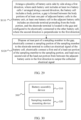
- This disclosure provides a manufacturing method of the battery 100.
- the manufacturing method includes the following steps.
- the second end of the lead-out portion 22 is led out from between the adjacent battery units 10, which can prevent occupation of extra space, increase the extension length of the second end of the lead-out portion 22, facilitate the electrical connection with the signal output component, and improve the reliability of the electrical connection.
- This allows for accurate collection of the electrical signals of the battery cells 1 and reliable monitoring of the battery cells 1 to discover abnormal situations, so as to facilitate timely control and handling, and improve the operating reliability of the battery 100.
- the welding area can be increased, so as to prevent virtual contact or disconnection of the welding point caused by long-term vibration or impact, thus improving the welding reliability.
Landscapes
- Chemical & Material Sciences (AREA)
- Chemical Kinetics & Catalysis (AREA)
- Electrochemistry (AREA)
- General Chemical & Material Sciences (AREA)
- Engineering & Computer Science (AREA)
- Manufacturing & Machinery (AREA)
- Connection Of Batteries Or Terminals (AREA)
Abstract
Description
- This application relates to the field of battery technologies, and in particular, to a battery, a manufacturing method and a manufacturing apparatus thereof, and an electric apparatus.
- With the advantages of high energy density, high power density, long cycle life, long storage time, and the like, lithium-ion batteries have been widely used in electric vehicles.
- However, how operating reliability of electric vehicle batteries is improved remains a difficult problem in the industry.
- This application is intended to improve operating reliability of batteries.
- According to a first aspect of this application, a battery is provided, including:
- a plurality of battery units arranged side by side along a first direction, where each battery unit includes at least two battery cells arranged along a second direction, the battery cell includes a body portion, a gap is formed between the body portions of at least one pair of adjacent battery cells in the battery unit, at least one battery cell in the adjacent battery cells includes an electrode terminal protruding from the body portion, and the electrode terminal is located in the gap and configured to be electrically connected to the other battery cell, where the second direction is perpendicular to the first direction; and
- a sampling member at least partially located in the gap, where the sampling member includes a sampling portion and a lead-out portion, the sampling portion is electrically connected to the electrode terminal and is configured to collect an electrical signal of the battery cell, a first end of the lead-out portion is electrically connected to the sampling portion, a second end of the lead-out portion is led out from between the adjacent battery units along the first direction, and the lead-out portion is configured to output the collected electrical signal.
- In this embodiment of this application, the second end of the lead-out portion is led out from between the adjacent battery units, which can prevent occupation of extra space, increase the extension length of the second end of the lead-out portion, facilitate the electrical connection with a signal output component, and improve the reliability of the electrical connection. This allows for accurate collection of the electrical signals of the battery cells and reliable monitoring of the battery cells to discover abnormal situations, so as to facilitate timely control and handling, and improve the operating reliability of the battery. For example, in welding the second end of the lead-out portion to the signal output component, the welding area can be increased, so as to prevent virtual contact or disconnection of the welding point caused by long-term vibration or impact, thus improving the welding reliability.
- Moreover, this arrangement also leaves operation space for the connection between the sampling portion and the electrode terminal, improving the reliability of the electrical connection between the sampling portion and the electrode terminal, facilitating the assembly and optimizing the assembly effect.
- In some embodiments, the lead-out portion does not extend beyond an outer side surface of the battery cell in a third direction, where the third direction is perpendicular to the first direction and the second direction.
- This embodiment can make the sampling member not extend beyond the outer side surface of the battery cell in the third direction on the basis of increasing the extension length of the second end of the lead-out portion, so that arrangement of the adjacent battery cells is not affected. This can minimize the size occupied by a sampling function related structure in the third direction, thus improving the energy density of the battery.
- In some embodiments, in the second direction, the second end of the lead-out portion extends along a direction leaving the electrode terminal.
- In this embodiment, the second end of the lead-out portion extends in the second direction, that is, parallel to the side wall of the body portion, which is convenient for increasing the extension length of the second end of the lead-out portion, increasing the size of the lead-out portion along the first direction, and preventing the second end of the lead-out portion from affecting the side wall of the body portion.
- In some embodiments, in the second direction, the second end of the lead-out portion extends beyond the gap.
- In this embodiment, the second end of the lead-out portion extends beyond the gap, which can increase the extension length of the second end of the lead-out portion, facilitate the electrical connection with the signal output component, and improve the reliability of the electrical connection, so as to accurately collect the electrical signals of the battery cells.
- In some embodiments, the first end of the lead-out portion is close to the side end of the sampling portion in the second direction, and in the second direction, the second end of the lead-out portion extends along a direction leaving the sampling portion.
- In this embodiment, the first end of the lead-out portion is connected to one end of the sampling portion in the second direction, so that an operation space can be reserved for the connection between the sampling portion and the electrode terminal. Additionally, in the second direction, the second end of the lead-out portion extends along a direction leaving the sampling portion, so that an extension direction of the second end of the lead-out portion is independent of the operation region where the sampling portion and the electrode terminal are connected. This facilitates the connection between the second end of the lead-out portion and the signal output component, as well as the connection between the sampling portion and the electrode terminal, thus facilitating assembly and improving assembly performance. Moreover, in forming the sampling member through a thin plate, such design is also convenient for forming the sampling member by cutting and bending the whole thin plate, with no need to connect the sampling portion and the lead-out portion additionally, thus reducing the manufacturing difficulty of the sampling member.
- In some embodiments, the first end of the lead-out portion is connected to a position of the sampling portion in a center of the battery cell along the first direction, and the second end of the lead-out portion extends to a position between the adjacent battery units along the first direction.
- In this embodiment, the extension length of the lead-out portion along the first direction can be designed in such a way that the second end of the lead-out portion is located between adjacent battery units, to facilitate control of the lead-out position of the second end of the lead-out portion. Moreover, in order that the first end of the lead-out portion is easily connected to the sampling portion and that the second end of the lead-out portion extends along the first direction, the region of the lead-out portion close to the sampling portion can be designed to form a bending structure in a plane perpendicular to the second direction, thus improving the rigidity of the lead-out portion and preventing the lead-out portion from being deformed after assembly and mounting.
- In some embodiments, the sampling member includes a plurality of sampling portions spaced apart along the first direction, and the adjacent sampling portions are connected to each other.
- In this embodiment, the electrode terminals of the plurality of battery cells that are electrically connected to a plurality of connecting portions of one sampling member can be designed to have an equal potential, thus achieving voltage balance of the battery cells and improving consistency of detection parameters of the plurality of battery cells.
- In some embodiments, the plurality of sampling portions share one lead-out portion.
- In this embodiment, the plurality of sampling portions are electrically connected, and only one lead-out portion is needed to implement lead-out of electrical signals, thus simplifying the structure and reducing the materials used for the sampling member. Moreover, for the embodiment for arranging a mounting part, most of the lead-out portion can be integrally fastened in the mounting part by injection molding and encapsulation, and the second end of the lead-out portion does not need to be fastened to the mounting part, so there is no need to correspondingly arrange one lead-out portion for each sampling portion, and only one lead-out portion is needed for one sampling member.
- In some embodiments, the sampling member further includes a connecting portion, where the connecting portion is connected between adjacent sampling portions, the first end of the lead-out portion is connected at a position of the connecting portion between adjacent battery units, and the second end of the lead-out portion extends in the third direction, the third direction being perpendicular to the first direction and the second direction.
- In this embodiment, adjacent sampling portions are electrically connected through the connecting portion, so that the plurality of sampling portions can be connected into a whole. Additionally, the first end of the lead-out portion is directly connected to the position of the connecting portion between the battery units, so that the second end of the lead-out portion can reach the position between the adjacent battery units when the second end of the lead-out portion directly extends in the third direction, thus simplifying the structure of the lead-out portion.
- In some embodiments, two ends of the connecting portion are respectively connected to the positions of adjacent sampling portions close to the lead-out portion in the third direction.
- This embodiment is beneficial to ensure the relative positions of the sampling portions, so that the sampling portions are aligned with the electrode terminals for connection, preventing the electrode terminals from being subjected to lateral pulling force during mounting of the sampling portions. Moreover, for the structure for arranging the mounting part subsequently, the connecting portion can be encapsulated and molded in the mounting part to implement more reliable fixation between the sampling member and the mounting part, so as to reduce the acting force on the lead-out portion. In addition, this structure can also reduce the overall length of the lead-out portion, which is beneficial to improve the rigidity of the lead-out portion and prevent the lead-out portion from being deformed.
- In some embodiments, the sampling portion is of a partially annular structure, and the two ends of the connecting portion are connected to the respective adjacent end portions of the adjacent sampling portions.
- In this embodiment, the two ends of the connecting portion are connected to the respective adjacent end portions of adjacent sampling portions, so that when the battery is subjected to vibration or impact, the vibration or impact can be absorbed through the deformation of the connecting portion to prevent the adjacent sampling portions from being disconnected, thus improving the sampling reliability of the battery cells.
- In some embodiments, the connecting portion is provided with a deformable section configured to allow dislocation of the adjacent sampling portions.
- In this embodiment, when the battery is subjected to vibration or impact, the vibration or impact can be absorbed through the deformation of the deformable section, allowing for a small amount of dislocation of the adjacent sampling portions, preventing the adjacent sampling portions from being disconnected after long-term operation, and improving the sampling reliability of the battery cells.
- In some embodiments, a mounting part is further included, which is mounted on the battery cell and connected to the sampling member. An accommodating groove is provided on the mounting part and is configured to accommodate the second end of the lead-out portion, and the accommodating groove is provided on a surface of the mounting part far away from the battery unit in the third direction and is located at a position between adjacent battery units in the first direction; where the third direction is perpendicular to the first direction and the second direction.
- In this embodiment, the mounting part is provided to facilitate the connection of the sampling member and position the sampling member relative to the battery cell, thus ensuring the position accuracy of the mounted sampling member and preventing the sampling member from shaking. Moreover, the accommodating groove is provided on the mounting part to accommodate the second end of the lead-out portion, which can protect the second end of the lead-out portion, prevent the second end of the lead-out portion from being deformed due to collision during assembly, and ensure the insulation of the second end of the lead-out portion.
- In some embodiments, the mounting part is provided with an opening, the opening is disposed opposite the electrode terminal in the first direction, and the opening is configured to form a channel for connecting the sampling portion and the electrode terminal.
- In this embodiment, the opening is provided on the mounting part to provide an operation space for connecting the sampling portion and the electrode terminal, which facilitates assembly of the sampling member and improves the connection reliability between the sampling portion and the electrode terminal. Moreover, the accommodating groove is located on one side of the opening in the second direction, so that the operation space for connecting the sampling portion and the electrode terminal is spatially independent of the second end of the lead-out portion, thus facilitating assembly and improving assembly performance.
- In some embodiments, the mounting part has a supporting portion configured to support the second end of the lead-out portion.
- In this embodiment, support can be provided for the second end of the lead-out portion when pressure is applied in the third direction to connect the signal output component and the second end of the lead-out portion, so as to prevent the mounting part from being crashed, thus improving the connection reliability between the signal output component and the second end of the lead-out portion and facilitating the application of pressure during assembly.
- In some embodiments, the sampling portion is connected to a circumferential side wall of the electrode terminal.
- In this embodiment, the sampling portion is connected to the circumferential side wall of the electrode terminal, which can improve the reliability and stability of the connection and keep the contact area between the sampling portion and the electrode terminal stable, thus improving the accuracy of the sampling results.
- In some embodiments, the electrode terminals of at least one pair of adjacent battery cells in the battery unit are interconnected in the second direction, and the sampling portion is electrically connected to the two electrode terminals.
- In this embodiment, the size of the sampling portion in the second direction can be increased, improving the connection stability between the sampling portion and the electrode terminal.
- In some embodiments, the sampling portion is of a partially annular structure, and the sampling portion is in interference fit with the electrode terminal.
- The mounting manner of this embodiment makes the sampling member easy to assemble and mount, and facilitates automation, thus reducing the requirements for the assembly device, improving assembly efficiency, and reducing costs.
- In some embodiments, the sampling portion is of a partially annular structure and is laser-welded to the electrode terminal.
- The mounting manner of this embodiment can lower the dimensional matching requirement between the sampling portion and the electrode terminal, and implement sound and reliable connection between the sampling portion and the electrode terminal, so that the resistance value is stable after connection, thus improving the accuracy and stability of the voltage signal collection results.
- In some embodiments, a protruding portion is provided on an inner wall of the sampling portion, and the protruding portion is in contact with the circumferential side wall of the electrode terminal.
- In this embodiment, the protruding portion is provided on the inner wall of the sampling portion, which can increase the clamping force between the sampling portion and the electrode terminal, and improve the connection reliability and firmness, making the signal collection results more stable.
- In some embodiments, the sampling portion includes a first snap ring and a second snap ring, and the first snap ring and the second snap ring together surround the circumferential side wall of the electrode terminal.
- In this embodiment, the first snap ring and the second snap ring surround the entire circumferential side wall of the electrode terminal, so that the connection is reliable, improving the sampling accuracy.
- In some embodiments, the sampling member further includes an elastic conductive layer disposed on an inner wall of at least one of the first snap ring and the second snap ring.
- In this embodiment, the elastic conductive layer is disposed to increase the clamping force applied by the sampling member to the electrode terminal, prevent the electrode terminal from being damaged by hard contact between the sampling member and the electrode terminal, and lower the dimensional machining accuracy requirement on the first snap ring and the second snap ring.
- According to a second aspect of this application, an electric apparatus is provided, including the battery according to the foregoing embodiments, where the battery is configured to provide electrical energy for the electric apparatus.
- According to a third aspect of this application, a manufacturing method of a battery is provided, including:
- arranging a plurality of battery units side by side along a first direction, where each battery unit includes at least two battery cells arranged along a second direction, the battery cell includes a body portion, a gap is formed between the body portions of at least one pair of adjacent battery cells in the battery unit, at least one battery cell in the adjacent battery cells includes an electrode terminal protruding from the body portion, and the electrode terminal is located in the gap and configured to be electrically connected to the other battery cell; where the second direction is perpendicular to the first direction; and
- disposing at least part of a sampling member in the gap, electrically connecting a sampling portion of the sampling member to the electrode terminal to collect an electrical signal of the battery cell, electrically connecting a first end of a lead-out portion of the sampling member to the sampling portion, and leading out a second end of the lead-out portion from between the adjacent battery units in the first direction to output the collected electrical signal.
- According to a fourth aspect of this application, a manufacturing apparatus of a battery is provided, including:
- a battery assembly device, configured to arrange a plurality of battery units side by side along a first direction, where each battery unit includes at least two battery cells arranged along a second direction, the battery cell includes a body portion, a gap is formed between the body portions of at least one pair of adjacent battery cells in the battery unit, at least one battery cell in the adjacent battery cells includes an electrode terminal protruding from the body portion, and the electrode terminal is located in the gap and configured to be electrically connected to the other battery cell; where the second direction is perpendicular to the first direction; and
- a sampling member mounting device, configured to dispose at least part of a sampling member in the gap, electrically connect a sampling portion of the sampling member to the electrode terminal to collect an electrical signal of the battery cell, electrically connect a first end of a lead-out portion of the sampling member to the sampling portion, and lead out a second end of the lead-out portion from between the adjacent battery units in the first direction to output the collected electrical signal.
- To describe the technical solutions of the embodiments of this application more clearly, the following briefly describes the accompanying drawings required for describing the embodiments of this application. It will be apparent that the accompanying drawings described below show merely some embodiments of this application, and persons of ordinary skill in the art may still derive other drawings from the accompanying drawings without creative efforts.
-
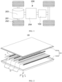
FIG. 1 is a schematic structural diagram of some embodiments of a battery installed in a vehicle according to this application. -
FIG. 2 is an exploded view of some embodiments of the battery according to this application. -
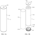
FIG. 3A and FIG. 3B are outline views and exploded views of some embodiments of a battery cell according to this application. -
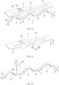
FIG. 4 is a schematic structural diagram of a sampling member mounted on battery cells according to a first embodiment. -
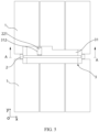
FIG. 5 is a top view ofFIG. 4 . -
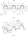
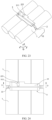
FIG. 6 is a cross-sectional view ofFIG. 5 along A-A. -
FIG. 7 is a schematic structural diagram of connection between a sampling member and a mounting part according to the first embodiment. -
FIG. 8 is a schematic structural diagram of a mounting part according to the first embodiment. -
FIG. 9 is a schematic structural diagram of a sampling member according to the first embodiment. -
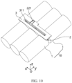
FIG. 10 is a schematic structural diagram of a sampling member mounted on battery cells according to a second embodiment. -
FIG. 11 is a top view ofFIG. 10 . -
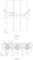
FIG. 12 is a cross-sectional view ofFIG. 11 along B-B. -
FIG. 13 is a schematic structural diagram of connection between a sampling member and a mounting part according to the second embodiment. -
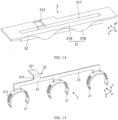
FIG. 14 is a schematic structural diagram of a mounting part according to the second embodiment. -
FIG. 15 is a schematic structural diagram of a sampling member according to the second embodiment. -
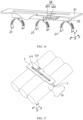
FIG. 16 is a schematic structural diagram of a mounting part provided with a supporting portion according to the second embodiment. -
FIG. 17 is a schematic structural diagram of a sampling member mounted on battery cells according to a third embodiment. -
FIG. 18 is a top view ofFIG. 17 . -
FIG. 19 is a cross-sectional view ofFIG. 18 along C-C. -
FIG. 20 is a schematic structural diagram of connection between a sampling member and a mounting part according to the third embodiment. -
FIG. 21 is a schematic structural diagram of a mounting part according to the third embodiment. -
FIG. 22 is a schematic structural diagram of a sampling member according to the third embodiment. -
FIG. 23 is a schematic structural diagram of a sampling member mounted on battery cells according to a fourth embodiment. -
FIG. 24 is a top view ofFIG. 23 . -
FIG. 25 is a cross-sectional view ofFIG. 24 along D-D. -
FIG. 26 is a schematic structural diagram of connection between a sampling member and a mounting part according to the fourth embodiment. -
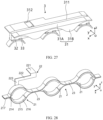
FIG. 27 is a schematic structural diagram of a mounting part according to the fourth embodiment. -
FIG. 28 is a schematic structural diagram of a sampling member according to the fourth embodiment. -
FIG. 29 is a schematic flowchart of some embodiments of a manufacturing method of a battery according to this application. -
FIG. 30 is a schematic module composition diagram of some embodiments of a manufacturing apparatus of a battery according to this application. - The accompanying drawings are not drawn to scale.
- Reference signs are described as follows:
- 200. vehicle; 201. axle; 202. wheel; 203. motor; 204. controller;
- 100. battery; 101. housing assembly; 101A. cover; 101B. box body; 10. battery unit;
- 1. battery cell; 11. body portion; 12. electrode terminal; 111. housing; 1111. opening; 112. end cover; 113. electrode assembly; 1131. electrode tab; 114. adapter;
- 2. sampling member; 21. sampling portion; 211. protruding portion; 212. guide portion; 213. stiffener; 214. first snap ring; 215. second snap ring; 216. elastic conductive layer; 217. fastening portion; 22. lead-out portion; 221. bending section; 222. extension section; 223. connecting section; 23. connecting portion; 231. deformable section;
- 3. mounting part; 31. first portion; 31A. mounting plate; 31B. positioning portion; 311. groove; 312. accommodating groove; 313. opening; 32. second portion; 33. accommodating portion; 34. supporting portion; 341. first plate; 342. second plate;
- 300. manufacturing apparatus; 310. battery assembly device; 320. sampling member mounting device;
- x. first direction; y. second direction; and z. third direction.
- The following further describes the implementations of this application in detail with reference to the accompanying drawings and embodiments. The detailed description of embodiments and the accompanying drawings are intended to illustrate the principle of this application, rather than to limit the scope of this application, meaning this application is not limited to the embodiments described herein.
- In the description of this application, it should be noted that, unless otherwise stated, "multiple" means at least two; and the orientations or positional relationships indicated by the terms "upper", "lower", "left", "right", "inside", "outside", and the like are merely for ease and brevity of description of this application rather than indicating or implying that the means or components mentioned must have specific orientations or must be constructed or manipulated according to particular orientations. These terms shall therefore not be construed as limitations on this application.
- In addition, the terms "first", "second", "third", and the like are merely for the purpose of description and shall not be understood as any indication or implication of relative importance. "Perpendicular" is not perpendicular in the strict sense but within an allowable range of error. "Parallel" is not parallel in the strict sense but within an allowable range of error. The orientation terms appearing in the following description all are directions shown in the figures, and do not limit the specific structure of the application.
- In the description of this application, it should also be noted that unless otherwise specified and defined explicitly, the terms "mounting", "connection", and "join" should be understood in their general senses. For example, they may refer to a fixed connection, a detachable connection, or an integral connection, and may refer to a direct connection or an indirect connection via an intermediate medium. Persons of ordinary skill in the art can understand specific meanings of these terms in this application as appropriate to specific situations.
- In this specification, reference to "embodiment" means that specific features, structures, or characteristics described with reference to the embodiment may be incorporated in at least some embodiment of this application. The word "embodiment" appearing in various places in the specification does not necessarily refer to the same embodiment or an independent or alternative embodiment that is exclusive of other embodiments. It would be explicitly or implicitly understood by persons skilled in the art that the embodiments described herein may be combined with other embodiments.
- In the description of the embodiments of this application, the term "a plurality of" means more than two (inclusive). Similarly, "a plurality of groups" means more than two (inclusive) groups, and "a plurality of pieces" means more than two (inclusive) pieces.
- In this application, the orientations or positional relationships indicated by the terms "upper", "lower", "top", "bottom", "left", "right", "inside", "outside", and the like are merely for ease description of this application rather than indicating or implying that the means mentioned must have specific orientations or must be constructed or manipulated according to particular orientations. These terms shall therefore not be construed as limitations on the protection scope of this application.
- The battery mentioned in the embodiments of this application is a single physical module that includes multiple battery cells for providing higher voltage and capacity. For example, the battery mentioned in this application may include a battery module, a battery pack, or the like.
- The battery cell mentioned in the embodiments of this application typically includes a housing and an electrode assembly accommodated in the housing, and the housing is filled with electrolyte. The electrode assembly is mainly formed by stacking or winding a first electrode plate and a second electrode plate with opposite polarities, and a separator is typically sandwiched between the first electrode plate and the second electrode plate. The portions of the first electrode plate and the second electrode plate with active substances constitute a body portion of the electrode assembly, and the portions of the first electrode plate and the second electrode plate without active substances respectively constitute a first electrode tab and a second electrode tab. In a lithium ion battery, the first electrode plate may be a positive electrode plate including a positive electrode current collector and positive electrode active substance layers disposed on two sides of the positive electrode current collector. The material of the positive electrode current collector may be, for example, aluminum, and the positive electrode active substance may be, for example, lithium cobaltate, ferrous lithium phosphate, lithium ternary, or lithium manganate. The second electrode plate may be a negative electrode plate, including a negative electrode current collector and negative electrode active substance layers disposed on two sides of the negative electrode current collector. The material of the negative electrode current collector may be, for example, copper, and the negative electrode active substance may be, for example, graphite or silicon. The first electrode tab and the second electrode tab may both be located at one end of the body portion or be located at two ends of the body portion respectively. During charging and discharging of the battery cell, the positive electrode active substance and the negative electrode active substance react with an electrolyte, and the electrode tabs are connected to the terminals to form a current loop.
- In practice, the inventors have found that the design of the battery requires consideration of many design factors, for example, performance parameters such as energy density, cycle life, discharge capacity, and charge and discharge rate, as well as safety of the battery.
- At present, a battery of an electric vehicle often requires tens or even hundreds of battery cells.
- In practical applications, due to minor differences in some parameters (for example, voltage, internal resistance, and SOC (state of charge)) between battery cells, as the use time increases, differences between the battery cells become increasingly large. If these differences are neglected, consistency of the battery cells will be worse, affecting performance of the battery, and causing serious consequences, even causing fires, explosions, and other accidents. To solve this problem, a sampling member can be disposed in the battery to collect the electrical signal of the battery cell, so as to perform corresponding control and handling when abnormality is found.
- The battery cell includes a body portion and an electrode terminal disposed on the body portion. For a structure in which two battery cells are interconnected to implement electrical connection, the sampling member needs to be connected to the electrode terminals of the battery cells to collect the electrical signals of the battery cells, and the electrical signals are led out through a lead-out portion. In order not to affect the arrangement of adjacent battery cells, it is necessary to arrange the lead-out portion in a gap formed by the body portions of two battery cells.
- To facilitate the welding of the lead-out portion and the signal output component, which is not shown in the figures, the inventors thought of folding the end portion of the lead-out portion so that the folded portion extends in the width direction of the gap. However, considering that the protruding height of the electrode terminal is small and the gap formed is also small, the extension length of the lead-out portion cannot exceed the width of the gap, so the welding area between the end portion of the lead-out portion and the signal output component is small and the contact reliability is poor.
- In a case that the battery is subjected to vibration or impact during long-term operation, the solder joint at the connection between the lead-out portion and the signal output component is prone to fall off, which will result in false contact or separation between the lead-out portion and the signal output component, affecting the accuracy of electrical signal collection of the battery cell, or even leading to signal collection failure. In this case, the abnormality of the battery cell may not be detected, and timely control and handling cannot be implemented, affecting the operating reliability of the battery.
- In view of the above problems, the inventors believe that if the operation reliability of the battery is to be improved, the connection reliability between the lead-out portion in the sampling member and the signal output component needs to be improved. According to this idea, this application has improved the sampling function in the battery. The following will further describe the embodiments of this application with reference to the accompanying drawings.
- The electric apparatus includes a battery for supplying power to an apparatus. The apparatus may be a mobile phone, a portable device, a laptop, an electric scooter, an electric vehicle, a steamship, a spacecraft, an electric toy, an electric tool, or the like. For example, the spacecraft includes an airplane, a rocket, a space shuttle, and a spaceship. The electric toy can include a fixed or mobile electric toy, such as a game console, an electric vehicle toy, an electric ship toy, and an electric airplane toy. The electric tool can include an electric metal cutting tool, an electric grinding tool, an electric assembly tool, and an electric railway-specific tool, such as an electric drill, an electric grinder, an electric wrench, an electric screwdriver, an electric hammer, an electric impact drill, a concrete vibrator, and an electric planer.
- As shown in
FIG. 1 , the electric apparatus may be avehicle 200, for example, a new energy vehicle. The new energy vehicle may be a battery electric vehicle, a hybrid electric vehicle, an extended-range electric vehicle, or the like. Alternatively, the electric apparatus may be an unmanned aerial vehicle, a ship, or the like. Specifically, thevehicle 200 may include anaxle 201,wheels 202 connected to theaxle 201, amotor 203, acontroller 204, and abattery 100. Themotor 203 is used to drive theaxle 201 to rotate, and thecontroller 204 is used to control themotor 203 to work. Thebattery 100 may be arranged at the bottom, head, or tail of thevehicle 200 to provide electrical energy for themotor 203 and other components in the vehicle. - As shown in
FIG. 2 , to meet different power usage requirements, thebattery 100 may include a plurality ofbattery cells 1, where the plurality ofbattery cells 1 may be connected in series, parallel, or series and parallel, and being connected in series-parallel refers to a combination of series-parallel connections. -
FIG. 2 is a schematic structural diagram of some embodiments of thebattery 100 according to this application. Thebattery 100 may include ahousing assembly 101 and a plurality ofbattery units 10. Thehousing assembly 101 has a hollow structure inside. The plurality ofbattery cells 1 are accommodated in thehousing assembly 101. Eachbattery unit 10 includes a plurality ofbattery cells 1 arranged in a second direction y and electrically connected to each other. The plurality ofbattery units 10 are arranged in a first direction x. The first direction x is perpendicular to the second direction y. That is, the plurality ofbattery cells 1 in thebattery 100 are arranged in a matrix structure. Optionally, thebattery 100 may alternatively have only onebattery unit 10, and thebattery unit 10 includes a plurality ofbattery cells 1 arranged in the second direction y and electrically connected to each other. Thebattery 100 may further include at least onesampling member 2 configured to collect an electrical signal of thebattery cell 1. - For example, the
housing assembly 101 may include two parts, which are referred to as acover 101A and abox body 101B herein. Thecover 101A and thebox body 101B are fitted together. Shapes of thecover 101A and thebox body 101B may be determined based on a shape in which the plurality ofbattery cells 1 are combined. For example, thecover 101A and thebox body 101B each may be a hollow cuboid and have only one face with an opening, where the opening of thecover 101A is disposed opposite the opening of thebox body 101B, and thecover 101A and thebox body 101B are snap-fitted to form a box with a closed chamber. Alternatively, thecover 101A is a cuboid with an opening and thebox body 101B is in a plate shape, or thebox body 101B is a cuboid with an opening and thecover 101A is in a plate shape, and thecover 101A and thebox body 101B are disposed opposite each other and snap-fitted to form a box with a closed chamber. The plurality ofbattery cells 1 are connected in parallel, in series, or in series-parallel, and then placed into the box formed after thecover 101A and thebox body 101B are snap-fitted. - The
battery cell 1 may be, for example, a lithium-ion secondary battery, a lithium-ion primary battery, a lithium-sulfur battery, a sodium-ion battery, a magnesium-ion battery, or the like. - As shown in
FIG. 3A , thebattery cell 1 includes abody portion 11 and anelectrode terminal 12. Theelectrode terminal 12 is disposed at an end portion of thebody portion 11 along the second direction y, for example, may be disposed at one end or both ends. - As shown in
FIG. 3B , thebody portion 11 includes ahousing 111, anend cover 112, and anelectrode assembly 113. Thehousing 111 is a hollow structure for accommodating theelectrode assembly 113, and thehousing 111 has anopening 1111. For example, thehousing 111 may be cylindrical, flat, cuboid, or of other shapes. Theelectrode terminal 12 is disposed on theend cover 112 and closes theopening 1111 together with theend cover 112. - As shown in
FIG. 3B , theelectrode assembly 113 is disposed in thehousing 111, and the first electrode plate and the second electrode plate with opposite polarities each have anelectrode tab 1131, and theelectrode tab 1131 of the first electrode plate or theelectrode tab 1131 of the second electrode plate is electrically connected to theelectrode terminal 12. Thebattery cell 1 may further include anadapter 114. Theadapter 114 is disposed between theend cover 112 and theelectrode assembly 113 and configured to implement an electrical connection between theelectrode tab 1131 and theelectrode terminal 12. - In the embodiment shown in
FIG. 3A and FIG. 3B , thehousing 111 is a hollow cylinder withopenings 1111 at two ends, and each of the twoopenings 1111 is closed by theend cover 112 and theelectrode terminal 12 provided on theend cover 112. Theelectrode assembly 113 may be placed into thehousing 111 from theopening 1111. The first electrode plate and the second electrode plate are wound to form acylindrical electrode assembly 113. Therespective electrode tabs 1131 of the first electrode plate and the second electrode plate are led out from two ends of theelectrode assembly 113 along an axial direction, and are electrically connected to theelectrode terminals 12 at the corresponding ends through theadapter 114. - In other optional embodiments, the
housing 111 of thebattery cell 1 is a hollow cylinder with one end closed and the other end having anopening 1111 closed by theend cover 112. The first electrode plate and the second electrode plate are wound to form acylindrical electrode assembly 113. Therespective electrode tabs 1131 of the first electrode plate and the second electrode plate are respectively led out from two ends of theelectrode assembly 113 along an axial direction. Theelectrode tab 1131 of the first electrode plate, for example, a negative electrode plate, is electrically connected to theelectrode terminal 12 through theadapter 114. Theelectrode tab 1131 of the second electrode plate, for example, a positive electrode plate, is directly electrically connected to an end wall of thehousing 111. - The basic structures of the
battery 100 and thebattery cell 1 have been described. The following will describe the structures related to the sampling function in thebattery 100. - In some embodiments, as shown in
FIG. 4 to FIG. 9 , thebattery 100 includes asampling member 2 and a plurality ofbattery units 10. - A plurality of
battery units 10 are arranged side by side along a first direction x, where eachbattery unit 10 includes at least twobattery cells 1 arranged along a second direction y, thebattery cell 1 includes abody portion 11, a gap is formed between thebody portions 11 of at least one pair ofadjacent battery cells 1 in thebattery unit 10, at least onebattery cell 1 in theadjacent battery cells 1 includes anelectrode terminal 12 protruding from thebody portion 11 along the second direction y, and theelectrode terminal 12 is located in the gap and configured to be electrically connected to theother battery cell 1; where the second direction y is perpendicular to the first direction x. - The sampling
member 2 is at least partially located in the gap. The samplingmember 2 includes asampling portion 21 and a lead-outportion 22. Thesampling portion 21 is electrically connected to theelectrode terminal 12 and is configured to collect an electrical signal of thebattery cell 1. A first end of the lead-outportion 22 is electrically connected to thesampling portion 21, a second end of the lead-outportion 22 is led out from between theadjacent battery units 10 along the first direction x, and the lead-outportion 22 is configured to output the collected electrical signal. - The
adjacent battery cells 1 in thebattery unit 10 are electrically connected through interconnection, so that the twobattery cells 1 can be connected in series. - For example, for the
battery cells 1 with theelectrode terminals 12 disposed respectively at two ends of thebody portions 11,adjacent battery cells 1 may be connected in series by interconnecting theelectrode terminals 12, and at least twobattery cells 1 in thebattery unit 10 may be connected in series by sequentially interconnecting theelectrode terminals 12 along the second direction y. If theelectrode terminals 12 ofadjacent battery cells 1 all protrude from thebody portion 11, the size of the gap along the second direction y is a sum of the heights at which theelectrode terminals 12 of theadjacent battery cells 1 protrude from thebody portion 11. If only oneelectrode terminal 12 ofadjacent battery cells 1 protrudes from thebody portion 11 and theother electrode terminal 12 is flush with thebody portion 11, the size of the gap along the second direction y is the height at which theelectrode terminal 12 of the onebattery cell 1 protrudes from thebody portion 11. - For example, for a
battery cell 1 in which anelectrode terminal 12 is disposed at only one end of thebody portion 11 and an end wall of thebody portion 11 far away from theelectrode terminal 12 is used as theother electrode terminal 12,adjacent battery cells 1 may be connected in series by interconnecting theelectrode terminals 12 and the end walls of thebody portions 11, and at least twobattery cells 1 in thebattery unit 10 may be connected in series by sequentially interconnecting theelectrode terminals 12 and the end walls of thebody portions 11 along the second direction y. In this case, the size of the gap along the second direction y is the height at which theelectrode terminal 12 of the onebattery cell 1 protrudes from thebody portion 11. - If the
sampling member 2 is electrically connected to theelectrode terminal 12 of only onebattery unit 10, only voltage of thebattery cells 1 in onebattery unit 10 can be collected. If onesampling member 2 is electrically connected to theelectrode terminals 12 of a plurality ofbattery units 10 simultaneously, the plurality ofbattery units 10 can be connected in parallel through thesampling member 2, thereby implementing the series-parallel connection of a plurality ofbattery cells 1 in thebattery 100. The electrical signal obtained by the samplingmember 2 is the potential at theelectrode terminal 12 connected to thesampling member 2. The voltages at two ends of one ormore battery cells 1 can be calculated by obtaining the potentials ofdifferent electrode terminals 12. To collect electrical signals, the samplingmember 2 can be made of a conductive material such as metal. - The
sampling portion 21 can be electrically connected to theelectrode terminal 12 by snap-fitting or welding. Theelectrode terminal 12 can be a pole, and thesampling portion 21 can be designed as a shape matching at least part of the circumferential surface of the pole, so as to increase the contact area with the pole. For example, the pole is cylindrical, and thesampling portion 21 can be designed as a partial arc shape. The second end of the lead-outportion 22 is led out from between theadjacent battery units 10 along the first direction x. The lead-outportion 22 is configured to output the collected electrical signal to a signal output component. The signal output component is electrically connected to the second end of the lead-outportion 22 and transmits the signal to a battery management system, so as to monitor performance of thebattery 100 by monitoring state parameters of thebattery cells 1 in thebattery 100. - The
body portion 11 may be cylindrical, and there is a triangular gap betweenadjacent battery units 10 in the first direction x. The second end of the lead-outportion 22 is led out from betweenadjacent battery units 10, meaning that the second end of the lead-outportion 22 is located in the gap. In other words, in the first direction x, the second end of the lead-outportion 22 is staggered from the most protruding position of thebattery cell 1 in the third direction z, the third direction z being perpendicular to the first direction x and the second direction y. - In this embodiment of this application, the second end of the lead-out
portion 22 is led out from between theadjacent battery units 10, which can prevent occupation of extra space, increase the extension length of the second end of the lead-outportion 22, facilitate the electrical connection with the signal output component, and improve the reliability of the electrical connection. This allows for accurate collection of the electrical signals of thebattery cells 1 and reliable monitoring of thebattery cells 1 to discover abnormal situations, so as to facilitate timely control and handling, and improve the operating reliability of thebattery 100. For example, in welding the second end of the lead-outportion 22 to the signal output component, the welding area can be increased, so as to prevent virtual contact or disconnection of the welding point caused by long-term vibration or impact, thus improving the welding reliability. - Moreover, this arrangement also leaves operation space for the connection between the sampling
portion 21 and theelectrode terminal 12, improving the reliability of the electrical connection between the samplingportion 21 and theelectrode terminal 12, facilitating the assembly and optimizing the assembly effect. - In some embodiments, the lead-out
portion 22 does not extend beyond an outer side surface of thebattery cell 1 in a third direction z, where the third direction z is perpendicular to the first direction x and the second direction y. The second end of the lead-outportion 22 extends in a gap betweenadjacent battery cells 1 in the first direction x. - This embodiment can make the
sampling member 2 not extend beyond the outer side surface of thebattery cell 1 in the third direction z on the basis of increasing the extension length of the second end of the lead-outportion 22, so that arrangement of theadjacent battery cells 1 is not affected. This can minimize the size occupied by a sampling function related structure in the third direction z, thus improving the energy density of thebattery 100. - In some embodiments, in the second direction y, the second end of the lead-out
portion 22 extends along a direction leaving theelectrode terminal 12. - In this embodiment, the second end of the lead-out
portion 22 extends in the second direction y, that is, parallel to the side wall of thebody portion 11, which is convenient for increasing the extension length of the second end of the lead-outportion 22, increasing the size of the lead-outportion 22 along the first direction x, and preventing the second end of the lead-outportion 22 from affecting the side wall of thebody portion 11. - In some embodiments, in the second direction y, the second end of the lead-out
portion 22 extends beyond the gap. - In this embodiment, the second end of the lead-out
portion 22 extends beyond the gap, which can increase the extension length of the second end of the lead-outportion 22, facilitate the electrical connection with the signal output component, and improve the reliability of the electrical connection, so as to accurately collect the electrical signals of thebattery cells 1. - In some embodiments, as shown in
FIG. 9 , the first end of the lead-outportion 22 is close to the side end of thesampling portion 21 in the second direction y, and in the second direction y, the second end of the lead-outportion 22 extends along a direction leaving thesampling portion 21. - In this embodiment, the first end of the lead-out
portion 22 is connected to one end of thesampling portion 21 in the second direction y, so that an operation space can be reserved for the connection between the samplingportion 21 and theelectrode terminal 12. Additionally, in the second direction y, the second end of the lead-outportion 22 extends along a direction leaving thesampling portion 21, so that an extension direction of the second end of the lead-outportion 22 is independent of the operation region where thesampling portion 21 and theelectrode terminal 12 are connected. This facilitates the connection between the second end of the lead-outportion 22 and the signal output component, as well as the connection between the samplingportion 21 and theelectrode terminal 12, thus facilitating assembly and improving assembly performance. Moreover, in forming thesampling member 2 through a thin plate, such design is also convenient for forming thesampling member 2 by cutting and bending the whole thin plate, with no need to connect thesampling portion 21 and the lead-outportion 22 additionally, thus reducing the manufacturing difficulty of thesampling member 2. - In some embodiments, as shown in
FIG. 9 , the first end of the lead-outportion 22 is connected to a position of thesampling portion 21 in a center of thebattery cell 1 along the first direction x, and the second end of the lead-outportion 22 extends to a position between theadjacent battery units 10 along the first direction x. - Optionally, to facilitate the connection between the first end of the lead-out
portion 22 and thesampling portion 21, the lead-outportion 22 may include a connectingsection 223 and anextension section 222, where a first end of the connectingsection 223 is connected to thesampling portion 21 and in the third direction z, extends in a direction leaving thesampling portion 21, the first end of the connectingsection 223 serves as the first end of the lead-outportion 22, and an end of theextension section 222 is connected to a second end of the connectingsection 223 and extends in the first direction x. An L-shaped structure is formed between the connectingsection 223 and theextension section 222, which helps improve the rigidity of the lead-outportion 22, preventing the lead-outportion 22 from being deformed after assembly and mounting. - In this embodiment, the extension length of the lead-out
portion 22 along the first direction x can be designed in such a way that the second end of the lead-outportion 22 is located betweenadjacent battery units 10, to facilitate control of the lead-out position of the second end of the lead-outportion 22. Moreover, in order that the first end of the lead-outportion 22 is easily connected to thesampling portion 21 and that the second end of the lead-outportion 22 extends in the first direction x, the region of the lead-outportion 22 close to thesampling portion 21 can be designed to form a bending structure in a plane perpendicular to the second direction y, thus improving the rigidity of the lead-outportion 22 and preventing the lead-outportion 22 from being deformed after assembly and mounting. - In some embodiments, the sampling
member 2 includes a plurality ofsampling portions 21 spaced apart along the first direction x, and theadjacent sampling portions 21 are connected to each other. - The
whole sampling member 2 is made of a conductive material, and theadjacent sampling portions 21 are electrically connected, thus implementing parallel connection of a plurality ofbattery cells 1 arranged side by side in a plurality ofbattery units 10. Specifically, the samplingmember 2 may further include a connectingportion 23, and the connectingportion 23 is connected between theadjacent sampling portions 21 to implement electrical connection between theadjacent sampling portions 21. The samplingmember 2 may simultaneously collect electrical signals from the plurality ofbattery cells 1 arranged in the first direction x, and theelectrode terminals 12 of the plurality ofbattery cells 1 that are electrically connected to a plurality ofsampling portions 21 of onesampling member 2 have an equal potential. - In this embodiment, the
electrode terminals 12 of the plurality ofbattery cells 1 that are electrically connected to a plurality ofsampling portions 21 of onesampling member 2 can be designed to have an equal potential, thus achieving voltage balance of thebattery cells 1 and improving consistency of detection parameters of the plurality ofbattery cells 1. - In some embodiments, as shown in
FIG. 9 , the plurality ofsampling portions 21 share one lead-outportion 22. - In this embodiment, the plurality of
sampling portions 21 are electrically connected, and only one lead-outportion 22 is needed to implement lead-out of electrical signals, thus simplifying the structure and reducing the materials used for thesampling member 2. Moreover, for the embodiment for arranging a mountingpart 3, most of the lead-outportion 22 can be integrally fastened in the mountingpart 3 by injection molding and encapsulation, and the second end of the lead-outportion 22 does not need to be fastened to the mountingpart 3, so there is no need to correspondingly arrange one lead-outportion 22 for each samplingportion 21, and only one lead-outportion 22 is needed for onesampling member 2. - In some embodiments, as shown in
FIG. 9 , thesampling portion 21 is of a partially annular structure, and the two ends of the connectingportion 23 are connected to the respective adjacent end portions of theadjacent sampling portions 21. The connectingportions 23 between each pair ofadjacent sampling portions 21 are independent of each other. For example, thesampling portion 21 and the connectingportion 23 can be integrally formed by bending a strip-shaped thin plate structure. - For such structure, the first end of the lead-out
portion 22 can be connected to thesampling portion 21, for example, disposed at the end portion of thesampling portion 21 in the second direction y. Alternatively, the first end of the lead-outportion 22 may be connected to the connectingportion 23, for example, disposed at the end portion of the connectingportion 23 in the second direction y. - To facilitate the connection between the sampling
portion 21 and theelectrode terminal 12, the partially annular structuredsampling portion 21 is elastic, and the two ends of the connectingportion 23 are connected to the respective adjacent end portions ofadjacent sampling portions 21, so that when thebattery 100 is subjected to vibration or impact, the vibration or impact can be absorbed through the deformation of the connectingportion 23 to prevent theadjacent sampling portions 21 from being disconnected, thus improving the sampling reliability of thebattery cells 1. - In some embodiments, as shown in
FIG. 9 , the connectingportion 23 is provided with adeformable section 231 configured to allow dislocation of theadjacent sampling portions 21. - The deformable section can be made of an elastic material, or part of the length section of the connecting
portion 23 can be integrally arched up to form a deformable structure, for example, the arched shape may be C-shaped, rectangular, triangular, wavy, zigzag, or of other shapes. - In this embodiment, when the
battery 100 is subjected to vibration or impact, the vibration or impact can be absorbed through the deformation of thedeformable section 231, allowing for a small amount of dislocation of theadjacent sampling portions 21, preventing theadjacent sampling portions 21 from being disconnected after long-term operation, and improving the sampling reliability of thebattery cells 1. - In some embodiments, as shown in
FIG. 10 to FIG. 16 , the samplingmember 2 further includes a connectingportion 23, where the connectingportion 23 is connected betweenadjacent sampling portions 21, the first end of the lead-outportion 22 is connected at a position of the connectingportion 23 betweenadjacent battery units 10, and the second end of the lead-outportion 22 extends in the third direction z, the third direction z being perpendicular to the first direction x and the second direction y. - The first end of the lead-out
portion 22 is connected to the connectingportion 23, which is equivalent to the first end of the lead-outportion 22 being connected to thesampling portion 21 through the connectingportion 23. - In this embodiment,
adjacent sampling portions 21 are electrically connected through the connectingportion 23, so that the plurality ofsampling portions 21 can be connected into a whole. Additionally, the first end of the lead-outportion 22 is directly connected to the position of the connectingportion 23 between thebattery units 10, so that the second end of the lead-outportion 22 can reach the position between theadjacent battery units 10 when the second end of the lead-outportion 22 directly extends in the third direction z, thus simplifying the structure of the lead-outportion 22. - In some embodiments, two ends of the connecting
portion 23 are respectively connected to the positions ofadjacent sampling portions 21 close to the lead-outportion 22 in the third direction z. The connectingportions 23 between each pair ofadjacent sampling portions 21 can be connected into a whole, for example, the connectingportion 23 includes a strip structure extending between the samplingportions 21 at two ends in the first direction x. - The connecting
portion 23 may be disposed at a side end of thesampling portion 21 in the second direction y and extend in a plane perpendicular to the second direction y, so as to prevent the connectingportion 23 from occupying the operation space for connecting thesampling portion 21 and theelectrode terminal 12. The first end of the lead-outportion 22 can be connected to the connectingportion 23. - This embodiment is beneficial to ensure the relative positions of the
sampling portions 21, so that thesampling portions 21 are aligned with theelectrode terminals 12 for connection, preventing theelectrode terminals 12 from being subjected to lateral pulling force during mounting of thesampling portions 21. Moreover, for the structure for arranging the mountingpart 3 subsequently, the connectingportion 23 can be encapsulated and molded in the mountingpart 3 to implement more reliable fixation between the samplingmember 2 and the mountingpart 3, so as to reduce the acting force on the lead-outportion 22. In addition, this structure can also reduce the overall length of the lead-outportion 22, which is beneficial to improve the rigidity of the lead-outportion 22 and prevent the lead-outportion 22 from being deformed. - In some embodiments, the
battery 100 further includes a mountingpart 3 mounted on thebattery cell 1 and connected to thesampling member 2. Anaccommodating groove 312 is provided on themouting part 3 and is configured to accommodate the second end of the lead-outportion 22, and theaccommodating groove 312 is provided on a surface of the mountingpart 3 far away from thebattery unit 10 in the third direction z and is located at a position betweenadjacent battery units 10 in the first direction x; where the third direction z is perpendicular to the first direction x and the second direction y. - The mounting
part 3 may include afirst portion 31 and asecond portion 32. Thefirst portion 31 may include a mountingplate 31A and apositioning portion 31B. The mountingplate 31A may be substantially a rectangular plate structure, and two ends of the mountingplate 31A in the second direction y may be overlapped on thebattery cells 1. Thepositioning portion 31B may be connected to a side of the mountingplate 31A close to thebattery cell 1 in the third direction z. For example, thepositioning portion 31B may have an arc outer contour, is located betweenadjacent battery cells 1 in the first direction x, and used for mounting and positioning through thebody portion 11. The joint between the positioningportion 31B and the mountingplate 31A may be transitioned via a fillet. Thesecond portion 32 may be of a rectangular structure, and thesecond portion 32 is connected to a side surface of thefirst portion 31 close to thebattery cell 1, and is located in the gap in the second direction y. The lead-outportion 22 or the connectingportion 23 may be fastened in thesecond portion 32 by injection molding and encapsulation to improve the insulation performance. In this way, the mountingplate 31A and thesecond portion 32 form a T-shaped structure, and thepositioning portion 31B can be located on one or two sides of thesecond portion 32 in the second direction y. - The lead-out
portion 22 further includes abending section 221, and thebending section 221 extends in a plane perpendicular to the third direction z, so as to apply pressure along the third direction z to connect the signal output component to thebending section 221, for example, by welding or riveting. For example, as shown inFIG. 9 , thebending section 221 is connected to a second end of theextension section 222. As shown inFIG. 10 , if the extension length of the second end of the lead-outportion 22 exceeds the gap in the second direction y, width of the mountingplate 31A provided with theaccommodating groove 312 can be extended in the second direction y, so that theaccommodating groove 312 is formed as a groove with closed periphery, improving the protection effect on the second end of the lead-outportion 22. Alternatively, as shown inFIG. 15 , thebending section 221 is connected to the connectingportion 23 through the connectingsection 223. For example, thebending section 221 may be of a rectangular structure, and correspondingly, theaccommodating groove 312 may also be of a rectangular structure. - In this embodiment, the mounting
part 3 is provided to facilitate the connection of thesampling member 2 and position the samplingmember 2 relative to thebattery cell 1, thus ensuring the position accuracy of the mountedsampling member 2 and preventing thesampling member 2 from shaking. Moreover, theaccommodating groove 312 is provided on the mountingpart 3 to accommodate the second end of the lead-outportion 22, which can protect the second end of the lead-outportion 22, prevent the second end of the lead-outportion 22 from being deformed due to collision during assembly, and ensure the insulation of the second end of the lead-outportion 22. - In some embodiments, as shown in
FIG. 10 andFIG. 11 , the mountingpart 3 is provided with anopening 313, theopening 313 is disposed opposite theelectrode terminal 12 in the first direction x, and theopening 313 is configured to form a channel for connecting thesampling portion 21 and theelectrode terminal 12. - The number of the
openings 313 is the same as that of thebattery cells 1 connected to thesampling member 2. When thesampling member 2 is connected to a plurality ofbattery cells 1, a plurality ofopenings 313 are spaced apart along the first direction x, and theaccommodating groove 312 can be located betweenadjacent openings 313 in the first direction x. During the assembly process, thesampling portion 21 and theelectrode terminal 12 can be connected through theopening 313, for example, by laser welding. Theopening 313 may be rectangular or of other shapes. Optionally, agroove 311 extending in the first direction x is disposed on a surface of the mountingpart 3 far away from thebattery cell 1 in the third direction z, and theopening 313 may be disposed on a bottom wall of thegroove 311. Such structure can reduce the depth of theopening 313, facilitating laser welding and guaranteeing the welding effect. - In this embodiment, the
opening 313 is provided on the mountingpart 3 to provide an operation space for connecting thesampling portion 21 and theelectrode terminal 12, which facilitates assembly of thesampling member 2 and improves the connection reliability between the samplingportion 21 and theelectrode terminal 12. Moreover, theaccommodating groove 312 is located on one side of theopening 313 in the second direction y, so that the operation space for connecting thesampling portion 21 and theelectrode terminal 12 is spatially independent of the second end of the lead-outportion 22, thus facilitating assembly and improving assembly performance. - In some embodiments, as shown in
FIG. 16 , the mountingpart 3 has a supportingportion 34 configured to support the second end of the lead-outportion 22. - The supporting
portion 34 may be provided on a side surface of the mountingplate 31A close to thebattery cell 1. For example, the supportingportion 34 includes afirst plate 341 and a plurality ofsecond plates 342, thefirst plate 341 may be disposed perpendicular to the third direction z, and the plurality ofsecond plates 342 may be perpendicular to thefirst plate 341 and spaced apart in parallel along the first direction x. - The lead-out
portion 22 may further include abending section 221, and thebending section 221 extends in a plane perpendicular to the third direction z as the second end of the lead-outportion 22, which is equivalent to providing a flange on the second end of the lead-outportion 22. When pressure is applied along the third direction z to connect the signal output component to thebending section 221, thebending section 221 can be supported by the supportingportion 34 to prevent the mountingplate 31A of the mountingpart 3 from being crushed. - In this embodiment, the second end of the lead-out
portion 22 can be supported when pressure is applied in the third direction z to connect the signal output component and the second end of the lead-outportion 22, so as to prevent the mountingpart 3 from being crashed, thus improving the connection reliability between the signal output component and the second end of the lead-outportion 22 and facilitating the application of pressure during assembly. - In some embodiments, the
sampling portion 21 is connected to a circumferential side wall of theelectrode terminal 12. - For example, the
sampling portion 21 may be of a partially annular structure, match and connect to part of a circumferential side wall of theelectrode terminal 12, for example, by welding or snap-fitting. Alternatively, thesampling portion 21 may surround the entire circumferential side wall of theelectrode terminal 12. Thesampling portion 21 may be a thin plate structure in the second direction y, or may have a preset thickness in the second direction y to increase the length for matching theelectrode terminal 12. For example, it may match theelectrode terminal 12 along the entire length section or part of the length section in the second direction y. - To increase strength of the
sampling portion 21, astiffener 213 may be disposed on an outer wall of thesampling portion 21. Thestiffener 213 may be a protrusion disposed outside thesampling portion 21. - To facilitate placement of the
electrode terminal 12 into thesampling portion 21, in a case that thesampling portion 21 is of a partially annular structure, thesampling portion 21 is provided withguide portions 212 at end portions along the circumference, and a gradually expanding structure is formed between theguide portions 212 at the two ends for guiding theelectrode terminal 12. - In this embodiment, the
sampling portion 21 is connected to the circumferential side wall of theelectrode terminal 12, which can improve the reliability and stability of the connection and keep the contact area between the samplingportion 21 and theelectrode terminal 12 stable, thus improving the accuracy of the sampling results. - In some embodiments, the
electrode terminals 12 of at least one pair ofadjacent battery cells 1 in thebattery unit 10 are interconnected in the second direction y, and thesampling portion 21 is electrically connected to the twoelectrode terminals 12. - For example, the
electrode terminal 12 may be of a cylindrical, rectangular columnar, or prismatic structure. Whenadjacent battery cells 1 are interconnected, theelectrode terminals 12 are aligned, the twoelectrode terminals 12 may be welded together, and thesampling portion 21 may be connected to both of the twoelectrode terminals 12. - In this embodiment, the size of the
sampling portion 21 in the second direction y can be increased, improving the connection stability between the samplingportion 21 and theelectrode terminal 12. Optionally, thesampling portion 21 may be connected to only oneelectrode terminal 12 to avoid the welding position. - In some embodiments, as shown in the figure, the
sampling portion 21 is of a partially annular structure, and thesampling portion 21 is in interference fit with theelectrode terminal 12. - The
sampling portion 21 can be elastic. During assembly, thesampling portion 21 can be snap-fitted onto the outer wall of theelectrode terminal 12 by applying a pressing force to thesampling member 2 in the third direction z. To implement snap-fitting, thesampling portion 21 needs to be more than half a ring. The interference fit allows for a tight fit between the samplingportion 21 and theelectrode terminal 12, preventing relative dislocation. - The mounting manner of this embodiment makes the
sampling member 2 easy to assemble and mount, and facilitates automation, thus lowering requirements for the assembly device, improving assembly efficiency, and reducing costs. - In some embodiments, the
sampling portion 21 is of a partially annular structure and is laser-welded to theelectrode terminal 12. - To facilitate mounting of the
sampling portion 21 on theelectrode terminal 12, thesampling portion 21 can be designed to be no more than half a ring. Alternatively, thesampling portion 21 may be designed to be more than half a ring, so as to snap-fit thesampling portion 21 with theelectrode terminal 12 before welding. - The mounting manner of this embodiment can lower the dimensional matching requirement between the sampling
portion 21 and theelectrode terminal 12, and implement sound and reliable connection between the samplingportion 21 and theelectrode terminal 12, so that the resistance value is stable after connection, thus improving the accuracy and stability of the voltage signal collection results. - In some embodiments, as shown in
FIG. 6 andFIG. 9 , a protrudingportion 211 is provided on an inner wall of thesampling portion 21, and the protrudingportion 211 is in contact with the circumferential side wall of theelectrode terminal 12. - For example, the protruding
portion 211 may include a plurality of bumps, bosses, ribs, or the like provided on the inner wall of thesampling portion 21. To allow the protrudingportion 211 to be formed by stamping, thesampling portion 21 has a recessed portion on the back of the protrudingportion 211. The protrudingportion 211 inFIG. 9 includes two groups of ribs distributed on two sides of the center line of thebattery cell 1, where each group of ribs includes a plurality of ribs spaced apart, and the ribs extend along the entire width of thesampling portion 21 in the second direction y, and inclination angles of the two groups of ribs relative to the second direction y are opposite. - In this embodiment, the protruding
portion 211 is provided on the inner wall of thesampling portion 21, which can increase the clamping force between the samplingportion 21 and theelectrode terminal 12, and improve the connection reliability and firmness, making the signal collection results more stable. - In some embodiments, as shown in
FIG. 26 , thesampling portion 21 includes afirst snap ring 214 and asecond snap ring 215, and thefirst snap ring 214 and thesecond snap ring 215 together surround the circumferential side wall of theelectrode terminal 12. Both thefirst snap ring 214 and thesecond snap ring 215 may be of a semi-ring structure. The circumferential side wall of theelectrode terminal 12 can be clamped by securing both sides of thefirst snap ring 214 and thesecond snap ring 215. - In this embodiment, the
first snap ring 214 and thesecond snap ring 215 surround the entire circumferential side wall of theelectrode terminal 12, so that the connection is reliable, improving the sampling accuracy. - In some embodiments, as shown in
FIG. 26 , the samplingmember 2 further includes an elasticconductive layer 216 disposed on an inner wall of at least one of thefirst snap ring 214 and thesecond snap ring 215. For example, thefirst snap ring 214 and thesecond snap ring 215 are both provided with an elasticconductive layer 216 on the inner wall in contact with theelectrode terminal 12. The elasticconductive layer 216 may be conductive foam or the like. - In this embodiment, the elastic
conductive layer 216 is disposed to increase the clamping force applied by the samplingmember 2 to theelectrode terminal 12, prevent theelectrode terminal 12 from being damaged by hard contact between the samplingmember 2 and theelectrode terminal 12, and lower the dimensional machining accuracy requirement on thefirst snap ring 214 and thesecond snap ring 215. - Four specific embodiments will be given below, but the structures protected by this application are not limited thereto.
- In a first embodiment, as shown in
FIG. 4 to FIG. 9 , thebattery 100 includes a mountingpart 3, asampling member 2, and a plurality ofbattery units 10. - As shown in
FIG. 4 andFIG. 5 , a plurality ofbattery units 10 are arranged side by side in a first direction x, and eachbattery unit 10 includes at least twobattery cells 1 arranged in a second direction y. For example, threebattery units 10 are provided, and eachbattery unit 10 includes twobattery cells 1. These twobattery cells 1 are connected in series by interconnecting theirrespective electrode terminals 12, a gap is formed betweenbody portions 11 of the twobattery cells 1, and at least part of thesampling member 2 is located in the gap. Thebody portion 11 and theelectrode terminal 12 are both cylindrical. - The mounting
part 3 is mounted on thebattery cell 1 and connected to thesampling member 2, and two ends of thefirst portion 31 of the mountingpart 3 in the second direction y are respectively lapped on thebattery cells 1 on two sides, so as to implement positioning and mounting through thebody portions 11 of thebattery cells 1. A surface of the mountingpart 3 far away from thebattery cell 1 in the third direction z is provided with agroove 311 and anaccommodating groove 312 extending in the first direction x. Provision of thegroove 311 facilitates weight reduction. Theaccommodating groove 312 is configured to accommodate the second end of thesampling member 2, and theaccommodating groove 312 is located on one side of thegroove 311 in the second direction y. - As shown in
FIG. 6 , the samplingmember 2 includes a plurality ofsampling portions 21 arranged corresponding to a plurality ofelectrode terminals 12 arranged along the first direction x. Thesampling portions 21 may be of a partially annular structure and are clamped onto the outer side wall of theelectrode terminal 12 through interference fit. The adjacent end portions of theadjacent sampling portions 21 are connected through a connectingportion 23, so that a plurality ofbattery cells 1 connected to asame sampling member 2 can be connected in parallel, facilitating voltage balance. The connectingportion 23 is provided with adeformable section 231. Thedeformable section 231 may be a rectangular protrusion formed by bending the thin plate-shaped connectingportion 23. Correspondingly, the mountingpart 3 may further include a plurality ofaccommodating portions 33. The plurality ofaccommodating portions 33 are connected to a surface of thesecond portion 32 close to thebattery cell 1, and all samplingportions 21 are embedded in one accommodatingportion 33. - As shown in
FIG. 7 , width of part of thedeformable section 231 is reduced to weaken the strength and facilitate deformation. Specifically, widths of two sides of the rectangular protrusion in the first direction x can be reduced. Thesampling portion 21 may be provided with protrudingportions 211, so that thesampling portion 21 can form a wavy structure. This can increase the clamping force between the samplingportion 21 and theelectrode terminal 12, thus ensuring the stable connection. - As shown in
FIG. 9 , the samplingmember 2 further includes a lead-outportion 22, a first end of the lead-outportion 22 is connected to a side end of one of thesampling portions 21 in the second direction y, for example, connected to theoutermost sampling portion 21, and a second end of the lead-outportion 22 is led out from between thebody portions 11 of twoadjacent battery cells 1 along the first direction x. - Specifically, the lead-out
portion 22 may include a connectingsection 223, anextension section 222, and abending section 221, a first end of the connectingsection 223 is connected to thesampling portion 21, a first end of theextension section 222 is connected to a second end of the connectingsection 223, thebending section 221 is connected to the second end of the connectingsection 223, the connectingsection 223 and theextension section 222 are located in a plane perpendicular to the second direction y, and thebending section 221 is bent with respect to theextension section 222 and extends in a plane perpendicular to the third direction z. Thebending section 221 is configured to be electrically connected to a signal output component. For example, the signal output component may be a conductive structure such as a nickel sheet. The lead-outportion 22 is fastened in the mountingpart 3 in advance by encapsulation and injection molding. - The sampling
member 2 in this embodiment can be formed by cutting and bending a thin plate, which is easy to process. The protrudingportion 211 on thesampling member 2 can be formed by stamping. - In this embodiment, during assembly, downward pressure is applied to the mounting
part 3 so that thesampling portion 21 is snap-fitted with theelectrode terminal 12. This structure features simple operation, high production efficiency, easy automation of assembly, and low cost. Thesampling portion 21 needs to be elastic to realize the snap-fitting. Moreover, thesampling portion 21 is separated from thebody portion 11 through theaccommodating portion 33, implementing an insulating function and improving the sampling safety. - In a second embodiment, as shown in
FIG. 10 to FIG. 16 , the difference from the first embodiment is that thesampling portion 21 and theelectrode terminal 12 are in interference fit and connected by laser welding, so that the connection is reliable and the resistance value is stable, thus lowering the material requirement of thesampling portion 21. - As shown in
FIG. 10 andFIG. 11 , a surface of the mountingpart 3 far away from thebattery cell 1 in the third direction z is provided with agroove 311. Thegroove 311 extends in the first direction x, and the bottom of thegroove 311 is provided with a plurality ofopenings 313 spaced apart in the first direction x. The plurality ofopenings 313 are opposite theelectrode terminals 12 of the plurality ofbattery cells 1 in the first direction x. The opening 313 forms a channel for laser-welding thesampling portion 21 and theelectrode terminal 12. - As shown in
FIG. 12 , the samplingmember 2 further includes a lead-outportion 22 and a connectingportion 23. The lead-outportion 22 and the connectingportion 23 are fastened in the mountingpart 3 by injection molding and encapsulation, so that thesampling member 2 and the mountingpart 3 form an integral structure. As shown inFIG. 13 , a plurality ofsampling portions 21 are exposed from below the mountingpart 3, and the remaining portion thereof are insulated through the mountingpart 3.FIG. 14 is a schematic structural diagram of the mountingpart 3. Thesecond portion 32 of the mountingpart 3 occupies the space in the gap and is configured to fasten the lead-outportion 22 and the connectingportion 23. This structure can enhance the connection between the samplingmember 2 and the mountingpart 3. - As shown in
FIG. 15 , the samplingmember 2 includes a plurality ofsampling portions 21, and theadjacent sampling portions 21 are connected through the connectingportion 23. Two ends of the connectingportion 23 may be respectively connected to the positions of thesampling portion 21 directly opposite the center of thebattery cell 1. All the connectingportions 23 may be connected together to form an integral strip structure extending in the first direction x. The connectingportion 23 may be of a thin plate structure, located in a plane perpendicular to the second direction y, and disposed at a side end of thesampling portion 21 in the second direction y. The first end of the lead-outportion 22 is connected to the middle position of one of the connectingportions 23, so that the second end of the lead-outportion 22 is led out from betweenadjacent battery cells 1 along the first direction x. Specifically, the lead-outportion 22 may include a connectingsection 223 and abending section 221, one end of the connectingsection 223 is connected to the middle position of the connectingportion 23, and the other end of the connectingsection 223 is connected to thebending section 221 to form an L-shape. Astiffener 213 may be provided on thesampling portion 21. - As shown in
FIG. 16 , the mountingpart 3 further includes a supportingportion 34 configured to provide a supporting force to thebending section 221 when pressure is applied to connect the signal output component to thebending section 221, so as to prevent the mountingpart 3 from being crushed. - In this embodiment, during assembly, downward pressure is applied to the mounting
part 3 to fasten thesampling portion 21 to theelectrode terminal 12, and the contact part between the samplingportion 21 and theelectrode terminal 12 is laser spot-welded through theopening 313. - In a third embodiment, as shown in
FIG. 17 to FIG. 22 , the difference from the second embodiment is that thesampling portion 21 and theelectrode terminal 12 is connected only by laser welding. The connection is reliable and the resistance value is stable, thus lowering the material requirement of thesampling portion 21. Moreover, no interference fit is required between the samplingportion 21 and theelectrode terminal 12, making the mounting easier. Thesampling portion 21 does not need to be connected by snap-fitting. When thesampling portion 21 is of a partially annular structure, it can also be set to be not more than half a circle, which reduces material usage and facilitates placement of theelectrode terminal 12 into thesampling portion 21. - As shown in
FIG. 17 andFIG. 18 , to realize laser welding, the mountingpart 3 is also provided with anopening 313. As shown inFIG. 19 , part of the length section of the lead-outportion 22 is fastened in the mountingpart 3 by injection molding and encapsulation, so that thesampling member 2 is integrally fastened to the mountingpart 3. The adjacent end portions ofadjacent sampling portions 21 are connected through the connectingportion 23, and outer ends of thesampling portions 21 located at two sides can also be provided with extension portions.FIG. 20 is a schematic structural diagram showing how the mountingpart 3 insulates part of the length section of the lead-outportion 22. A plurality ofsampling portions 21 are suspended from the mountingpart 3. -
FIG. 21 is a schematic structural diagram of the mountingpart 3, andFIG. 22 is a schematic structural diagram of thesampling member 2. The first end of the lead-outportion 22 is connected to the middle position of one of the connectingportions 23, so that the second end of the lead-outportion 22 is led out from betweenadjacent battery cells 1 along the first direction x. Specifically, the lead-outportion 22 may include a connectingsection 223 and abending section 221, one end of the connectingsection 223 is connected to the middle position of the connectingportion 23, and the other end of the connectingsection 223 is connected to thebending section 221 to form an L-shape. - In a fourth embodiment, as shown in
FIG. 23 to FIG. 28 , the difference from the first embodiment is that thesampling portion 21 includes afirst snap ring 214 and asecond snap ring 215, where thefirst snap ring 214 and thesecond snap ring 215 together surround the circumferential side wall of theelectrode terminal 12. Both thefirst snap ring 214 and thesecond snap ring 215 may be of a semi-ring structure. In a case that a plurality ofsampling portions 21 are provided, the adjacent end portions of the adjacent first snap rings 214 are connected through the connectingportion 23, and the adjacent end portions of the first snap rings 214 are also connected through the connectingportion 23. Further,fastening portions 217 are provided on the outer sides of thefirst snap ring 214 and thesecond snap ring 215 that are located at two ends. Thefirst snap ring 214 and thesecond snap ring 215 can be fastened through respective connectingportions 23 andfastening portions 217, for example, by laser welding or fastener connection. - As shown in
FIG. 26 , the samplingmember 2 further includes an elasticconductive layer 216 disposed on an inner wall of at least one of thefirst snap ring 214 and thesecond snap ring 215. For example, the elasticconductive layer 216 may be conductive foam or the like, and may be integrated on thefirst snap ring 214 and thesecond snap ring 215 in advance. When thefirst snap ring 214 and thesecond snap ring 215 are fastened, the elasticconductive layer 216 is compressed against the surface of theelectrode terminal 12. - In this embodiment, the parts are simple to form, and a reliable and stable connection can be formed between the sampling
portion 21 and theelectrode terminal 12, thus improving the accuracy of signal collection. - This disclosure provides a manufacturing method of the
battery 100. In some embodiments, as shown inFIG. 29 , the manufacturing method includes the following steps. - S110. Arrange a plurality of
battery units 10 side by side along a first direction x, where eachbattery unit 10 includes at least twobattery cells 1 arranged along a second direction y, thebattery cell 1 includes abody portion 11, a gap is formed between thebody portions 11 of at least one pair ofadjacent battery cells 1 in thebattery unit 10, at least onebattery cell 1 in theadjacent battery cells 1 includes anelectrode terminal 12 protruding from thebody portion 11, and theelectrode terminal 12 is located in the gap and configured to be electrically connected to theother battery cell 1; where the second direction y is perpendicular to the first direction x. -
S 120. Dispose at least part of asampling member 2 in the gap, electrically connect asampling portion 21 of thesampling member 2 to theelectrode terminal 12 to collect an electrical signal of thebattery cell 1, electrically connect a first end of a lead-outportion 22 of thesampling member 2 to thesampling portion 21, and lead out a second end of the lead-outportion 22 from between theadjacent battery units 10 in the first direction x to output the collected electrical signal. - In this embodiment of this application, the second end of the lead-out
portion 22 is led out from between theadjacent battery units 10, which can prevent occupation of extra space, increase the extension length of the second end of the lead-outportion 22, facilitate the electrical connection with the signal output component, and improve the reliability of the electrical connection. This allows for accurate collection of the electrical signals of thebattery cells 1 and reliable monitoring of thebattery cells 1 to discover abnormal situations, so as to facilitate timely control and handling, and improve the operating reliability of thebattery 100. For example, when welding the second end of the lead-outportion 22 to the signal output component, the welding area can be increased, so as to prevent virtual contact or disconnection of the welding point caused by long-term vibration or impact, thus improving the welding reliability. - Moreover, this arrangement also leaves operation space for the connection between the sampling
portion 21 and theelectrode terminal 12, improving the reliability of the electrical connection between the samplingportion 21 and theelectrode terminal 12, facilitating the assembly and optimizing the assembly effect. - Finally, this disclosure provides a
manufacturing apparatus 300 of thebattery 100. In some embodiments, themanufacturing apparatus 300 includes: - a
battery assembly device 310, configured to arrange a plurality ofbattery units 10 side by side along a first direction x, where eachbattery unit 10 includes at least twobattery cells 1 arranged along a second direction y, thebattery cell 1 includes abody portion 11, a gap is formed between thebody portions 11 of at least one pair ofadjacent battery cells 1 in thebattery unit 10, at least onebattery cell 1 in theadjacent battery cells 1 includes anelectrode terminal 12 protruding from thebody portion 11, and theelectrode terminal 12 is located in the gap and configured to be electrically connected to theother battery cell 1; where the second direction y is perpendicular to the first direction x; and - a sampling
member mounting device 320, configured to dispose at least part of asampling member 2 in the gap, electrically connect asampling portion 21 of thesampling member 2 to theelectrode terminal 12 to collect an electrical signal of thebattery cell 1, electrically connect a first end of a lead-outportion 22 of thesampling member 2 to thesampling portion 21, and lead out a second end of the lead-outportion 22 from between theadjacent battery units 10 in the first direction x to output the collected electrical signal. - Although this application has been described with reference to some preferred embodiments, various modifications to this application and replacements of the components therein with equivalents can be made without departing from the scope of this application. In particular, as long as there is no structural conflict, the various technical features mentioned in the embodiments can be combined in any manner. This application is not limited to the specific embodiments disclosed in this specification but includes all technical solutions falling within the scope of the claims.
Claims (24)
- A battery (100), comprising:a plurality of battery units (10) arranged side by side along a first direction (x), wherein each battery unit (10) comprises at least two battery cells (1) arranged along a second direction (y), the battery cell (1) comprises a body portion (11), a gap is formed between the body portions (11) of at least one pair of adjacent battery cells (1) in the battery unit (10), at least one battery cell (1) in the adjacent battery cells (1) comprises an electrode terminal (12) protruding from the body portion (11), and the electrode terminal (12) is located in the gap and configured to be electrically connected to the other battery cell (1); wherein the second direction (y) is perpendicular to the first direction (x); anda sampling member (2) at least partially located in the gap, wherein the sampling member (2) comprises a sampling portion (21) and a lead-out portion (22); the sampling portion (21) is electrically connected to the electrode terminal (12) and is configured to collect an electrical signal of the battery cell (1); and a first end of the lead-out portion (22) is electrically connected to the sampling portion (21), a second end of the lead-out portion (22) is led out from between the adjacent battery units (10) along the first direction (x), and the lead-out portion (22) is configured to output the collected electrical signal.
- The battery (100) according to claim 1, wherein the lead-out portion (22) does not extend beyond an outer side surface of the battery cell (1) in a third direction (z), wherein the third direction (z) is perpendicular to the first direction (x) and the second direction (y).
- The battery (100) according to claim 1 or 2, wherein in the second direction (y), the second end of the lead-out portion (22) extends along a direction leaving the electrode terminal (12).
- The battery (100) according to any one of claims 1 to 3, wherein in the second direction (y), the second end of the lead-out portion (22) extends beyond the gap.
- The battery (100) according to any one of claims 1 to 4, wherein the first end of the lead-out portion (22) is close to a side end of the sampling portion (21) in the second direction (y), and in the second direction (y), the second end of the lead-out portion (22) extends along a direction leaving the sampling portion (21).
- The battery (100) according to any one of claims 1 to 5, wherein the first end of the lead-out portion (22) is connected to a position of the sampling portion (21) in a center of the battery cell (1) along the first direction (x), and the second end of the lead-out portion (22) extends to a position between the adjacent battery units (10) along the first direction (x).
- The battery (100) according to any one of claims 1 to 6, wherein the sampling member (2) comprises a plurality of sampling portions (21) spaced apart along the first direction (x), and the adjacent sampling portions (21) are connected to each other.
- The battery (100) according to claim 7, wherein the plurality of sampling portions (21) share one lead-out portion (22).
- The battery (100) according to claim 7 or 8, wherein the sampling member (2) further comprises a connecting portion (23), the connecting portion (23) is connected between the adjacent sampling portions (21), the first end of the lead-out portion (22) is connected at a position of the connecting portion (23) between the adjacent battery units (10), and the second end of the lead-out portion (22) extends along the third direction (z), the third direction (z) being perpendicular to the first direction (x) and the second direction (y).
- The battery (100) according to claim 9, whereintwo ends of the connecting portion (23) are respectively connected to positions of the adjacent sampling portions (21) close to the lead-out portion (22) in the third direction (z); orthe sampling portion (21) is of a partially annular structure, and two ends of the connecting portion (23) are connected to the respective adjacent end portions of the adjacent sampling portions (21).
- The battery (100) according to claim 9 or 10, wherein the connecting portion (23) is provided with a deformable section (231) configured to allow dislocation between the adjacent sampling portions (21).
- The battery (100) according to any one of claims 1 to 11, further comprising: a mounting part (3) mounted on the battery cell (1) and connected to the sampling member (2), wherein an accommodating groove (312) is provided on the mounting part (3) and is configured to accommodate the second end of the lead-out portion (22), and the accommodating groove (312) is provided on a surface of the mounting part (3) far away from the battery unit (10) in the third direction (z), and is located at a position between the adjacent battery units (10) in the first direction (x); wherein the third direction (z) is perpendicular to the first direction (x) and the second direction (y).
- The battery (100) according to claim 12, wherein the mounting part (3) is provided with an opening (313), the opening (313) is disposed opposite the electrode terminal (12) in the first direction (x), and the opening (313) is configured to form a channel for connecting the sampling portion (21) and the electrode terminal (12).
- The battery (100) according to claim 12 or 13, wherein the mounting part (3) has a supporting portion (34) configured to support the second end of the lead-out portion (22).
- The battery (100) according to any one of claims 1 to 14, wherein the sampling portion (21) is connected to a circumferential side wall of the electrode terminal (12).
- The battery (100) according to any one of claims 1 to 15, wherein the respective electrode terminals (12) of at least one pair of adjacent battery cells (1) in the battery unit (10) are interconnected in the second direction (y), and the sampling portion (21) is electrically connected to the two electrode terminals (12).
- The battery (100) according to any one of claims 1 to 16, wherein the sampling portion (21) is of a partially annular structure, and the sampling portion (21) is in interference fit with the electrode terminal (12).
- The battery (100) according to any one of claims 1 to 17, wherein the sampling portion (21) is of a partially annular structure and is laser-welded to the electrode terminal (12).
- The battery (100) according to any one of claims 1 to 18, wherein a protruding portion (211) is provided on an inner wall of the sampling portion (21), and the protruding portion (211) is in contact with the circumferential side wall of the electrode terminal (12).
- The battery (100) according to any one of claims 1 to 16, wherein the sampling portion (21) comprises a first snap ring (214) and a second snap ring (215), and the first snap ring (214) and the second snap ring (215) together surround the circumferential side wall of the electrode terminal (12).
- The battery (100) according to claim 20, wherein the sampling member (2) further comprises an elastic conductive layer (216) disposed on an inner wall of at least one of the first snap ring (214) and the second snap ring (215).
- An electric apparatus, comprising the battery (100) according to any one of claims 1 to 21, wherein the battery (100) is configured to provide electrical energy to the electric apparatus.
- A manufacturing method of a battery (100), comprising:arranging (S110) a plurality of battery units (10) side by side along a first direction (x), wherein each battery unit (10) comprises at least two battery cells (1) arranged along a second direction (y), the battery cell (1) comprises a body portion (11), a gap is formed between the body portions (11) of at least one pair of adjacent battery cells (1) in the battery unit (10), at least one battery cell (1) in the adjacent battery cells (1) comprises an electrode terminal (12) protruding from the body portion (11), and the electrode terminal (12) is located in the gap and configured to be electrically connected to the other battery cell (1); wherein the second direction (y) is perpendicular to the first direction (x); anddisposing (S120) at least part of a sampling member (2) in the gap, electrically connecting a sampling portion (21) of the sampling member (2) to the electrode terminal (12) to collect an electrical signal of the battery cell (1), electrically connecting a first end of a lead-out portion (22) of the sampling member (2) to the sampling portion (21), and leading out a second end of the lead-out portion (22) from between the adjacent battery units (10) in the first direction (x) to output the collected electrical signal.
- A manufacturing apparatus (300) of a battery (100), comprising:a battery assembly device (310), configured to arrange a plurality of battery units (10) side by side along a first direction (x), wherein each battery unit (10) comprises at least two battery cells (1) arranged along a second direction (y), the battery cell (1) comprises a body portion (11), a gap is formed between the body portions (11) of at least one pair of adjacent battery cells (1) in the battery unit (10), at least one battery cell (1) in the adjacent battery cells (1) comprises an electrode terminal (12) protruding from the body portion (11), and the electrode terminal (12) is located in the gap and configured to be electrically connected to the other battery cell (1); wherein the second direction (y) is perpendicular to the first direction (x); anda sampling member mounting device (320), configured to dispose at least part of a sampling member (2) in the gap, electrically connect a sampling portion (21) of the sampling member (2) to the electrode terminal (12) to collect an electrical signal of the battery cell (1), electrically connect a first end of a lead-out portion (22) of the sampling member (2) to the sampling portion (21), and lead out a second end of the lead-out portion (22) from between the adjacent battery units (10) in the first direction (x) to output the collected electrical signal.
Applications Claiming Priority (1)
| Application Number | Priority Date | Filing Date | Title |
|---|---|---|---|
| PCT/CN2021/121141 WO2023050022A1 (en) | 2021-09-28 | 2021-09-28 | Battery, method and apparatus for manufacturing same, and electrical device |
Publications (2)
| Publication Number | Publication Date |
|---|---|
| EP4395000A1 true EP4395000A1 (en) | 2024-07-03 |
| EP4395000A4 EP4395000A4 (en) | 2024-10-16 |
Family
ID=85780931
Family Applications (1)
| Application Number | Title | Priority Date | Filing Date |
|---|---|---|---|
| EP21958621.1A Pending EP4395000A4 (en) | 2021-09-28 | 2021-09-28 | BATTERY, METHOD AND DEVICE FOR PRODUCING SAME AND ELECTRICAL DEVICE |
Country Status (4)
| Country | Link |
|---|---|
| US (1) | US20240243447A1 (en) |
| EP (1) | EP4395000A4 (en) |
| CN (1) | CN116670907A (en) |
| WO (1) | WO2023050022A1 (en) |
Families Citing this family (3)
| Publication number | Priority date | Publication date | Assignee | Title |
|---|---|---|---|---|
| EP4258443A4 (en) * | 2021-10-18 | 2024-10-30 | Contemporary Amperex Technology (Hong Kong) Limited | SCANNING ARRANGEMENT, MANUFACTURING METHOD THEREFOR, BATTERY AND ELECTRICAL DEVICE |
| US12567611B2 (en) * | 2024-02-12 | 2026-03-03 | Rivian Ip Holdings, Llc | Interwoven voltage sense harness of a battery |
| CN121866679A (en) * | 2024-08-15 | 2026-04-14 | 宁德时代新能源科技股份有限公司 | Battery device and electricity utilization device |
Family Cites Families (9)
| Publication number | Priority date | Publication date | Assignee | Title |
|---|---|---|---|---|
| JP4767009B2 (en) * | 2005-12-14 | 2011-09-07 | 日立ビークルエナジー株式会社 | Assembled battery |
| US8647766B2 (en) * | 2010-06-22 | 2014-02-11 | Ford Global Technologies, Llc | Voltage detection in a battery |
| JP5776935B2 (en) * | 2011-09-06 | 2015-09-09 | 株式会社オートネットワーク技術研究所 | Battery wiring module and battery module temperature control system |
| CN103715473B (en) * | 2012-09-29 | 2016-01-20 | 北京有色金属研究总院 | A kind of power battery thermal management system |
| KR102006529B1 (en) * | 2014-04-01 | 2019-08-01 | 센젠 즈룬 드라이빙 테크놀러지 포 일렉트릭 비이클 컴퍼니 리미티드 | Power battery and cell state acquisition apparatus thereof |
| KR101805546B1 (en) * | 2016-03-08 | 2017-12-07 | 삼성에스디아이 주식회사 | Battery pack having connection tab with bent portion |
| CN206742445U (en) * | 2017-05-18 | 2017-12-12 | 东莞市沃泰通新能源有限公司 | A kind of battery modules temperature detection structure |
| CN208939116U (en) * | 2018-11-30 | 2019-06-04 | 福州大学 | A two-way balanced heat dissipation device for vehicle power battery pack |
| CN113325322B (en) * | 2021-05-25 | 2025-11-28 | 深圳迈巨微电子科技有限责任公司 | Signal processing device, battery management device, and battery management system |
-
2021
- 2021-09-28 EP EP21958621.1A patent/EP4395000A4/en active Pending
- 2021-09-28 WO PCT/CN2021/121141 patent/WO2023050022A1/en not_active Ceased
- 2021-09-28 CN CN202180088199.6A patent/CN116670907A/en active Pending
-
2024
- 2024-03-27 US US18/618,908 patent/US20240243447A1/en active Pending
Also Published As
| Publication number | Publication date |
|---|---|
| WO2023050022A1 (en) | 2023-04-06 |
| EP4395000A4 (en) | 2024-10-16 |
| CN116670907A (en) | 2023-08-29 |
| US20240243447A1 (en) | 2024-07-18 |
Similar Documents
| Publication | Publication Date | Title |
|---|---|---|
| US20250105410A1 (en) | End cover assembly, battery cell, battery, and electric apparatus | |
| US20240243447A1 (en) | Battery, manufacturing method and manufacturing apparatus thereof, and electric apparatus | |
| EP4300702A1 (en) | Battery cell, battery, electric device, and method and device for manufacturing battery cell | |
| CN115458880B (en) | End cover assembly, energy storage device and electric equipment | |
| EP4152428B1 (en) | Battery cell, battery,power consumption device | |
| EP4333172A1 (en) | Battery cell, battery, electrical device, and method and device for fabricating battery cell | |
| EP4668467A1 (en) | Battery cell, battery, and electric apparatus | |
| EP4148845B1 (en) | Battery cell and manufacturing method and manufacturing system therefor, battery, and powered device | |
| US20220407190A1 (en) | Battery, device, and method and apparatus for manufacturing battery | |
| US20240283059A1 (en) | Battery cell, method and system for manufacturing battery cell, battery, and electrical device | |
| EP4120463A1 (en) | Battery, power apparatus, and battery manufacturing method and device | |
| US20240304959A1 (en) | End cover assembly, battery cell, battery, and electric device | |
| US20240396128A1 (en) | Battery cell, battery, and electric device | |
| US20250149743A1 (en) | Battery cell, battery and electrical apparatus | |
| EP4421975A1 (en) | Battery cell, battery, and electric device | |
| KR102812545B1 (en) | Batteries, electrical devices, battery manufacturing methods and manufacturing equipment | |
| EP4618305A1 (en) | Battery cell, battery and electric device | |
| US20240234988A1 (en) | Battery cell and manufacturing method and manufacturing system therefor, battery and electrical device | |
| US12025677B2 (en) | Battery, electric apparatus, and method for preparing battery | |
| EP4583277A1 (en) | Battery and electric device | |
| EP4465419A1 (en) | Battery and electric device | |
| US12224456B2 (en) | Connection component, battery cell, battery and electrical device | |
| EP4354556A1 (en) | Current-collecting component, battery cell, battery and electric device | |
| EP4693644A1 (en) | Battery cell, battery and electric device | |
| US20240145876A1 (en) | Battery cell, manufacturing method and manufacturing device thereof, battery, and electric apparatus |
Legal Events
| Date | Code | Title | Description |
|---|---|---|---|
| STAA | Information on the status of an ep patent application or granted ep patent |
Free format text: STATUS: THE INTERNATIONAL PUBLICATION HAS BEEN MADE |
|
| PUAI | Public reference made under article 153(3) epc to a published international application that has entered the european phase |
Free format text: ORIGINAL CODE: 0009012 |
|
| STAA | Information on the status of an ep patent application or granted ep patent |
Free format text: STATUS: REQUEST FOR EXAMINATION WAS MADE |
|
| 17P | Request for examination filed |
Effective date: 20240328 |
|
| AK | Designated contracting states |
Kind code of ref document: A1 Designated state(s): AL AT BE BG CH CY CZ DE DK EE ES FI FR GB GR HR HU IE IS IT LI LT LU LV MC MK MT NL NO PL PT RO RS SE SI SK SM TR |
|
| RAP1 | Party data changed (applicant data changed or rights of an application transferred) |
Owner name: CONTEMPORARY AMPEREX TECHNOLOGY(HONG KONG) LIMITED |
|
| A4 | Supplementary search report drawn up and despatched |
Effective date: 20240912 |
|
| RIC1 | Information provided on ipc code assigned before grant |
Ipc: H01M 50/502 20210101ALI20240906BHEP Ipc: H01M 10/48 20060101AFI20240906BHEP |
|
| DAV | Request for validation of the european patent (deleted) | ||
| DAX | Request for extension of the european patent (deleted) | ||
| GRAP | Despatch of communication of intention to grant a patent |
Free format text: ORIGINAL CODE: EPIDOSNIGR1 |
|
| STAA | Information on the status of an ep patent application or granted ep patent |
Free format text: STATUS: GRANT OF PATENT IS INTENDED |
|
| INTG | Intention to grant announced |
Effective date: 20260213 |
|
| RIC1 | Information provided on ipc code assigned before grant |
Ipc: H01M 10/48 20060101AFI20260206BHEP Ipc: H01M 50/502 20210101ALI20260206BHEP Ipc: H01M 50/204 20210101ALI20260206BHEP Ipc: H01M 50/209 20210101ALI20260206BHEP Ipc: H01M 50/244 20210101ALI20260206BHEP Ipc: H01M 50/503 20210101ALI20260206BHEP Ipc: H01M 50/569 20210101ALI20260206BHEP Ipc: H01M 50/213 20210101ALI20260206BHEP Ipc: H01M 50/507 20210101ALI20260206BHEP |
|
| GRAS | Grant fee paid |
Free format text: ORIGINAL CODE: EPIDOSNIGR3 |
|
| GRAA | (expected) grant |
Free format text: ORIGINAL CODE: 0009210 |
|
| STAA | Information on the status of an ep patent application or granted ep patent |
Free format text: STATUS: THE PATENT HAS BEEN GRANTED |