EP4394993A1 - Bag-making type stacking apparatus and stacked product - Google Patents
Bag-making type stacking apparatus and stacked product Download PDFInfo
- Publication number
- EP4394993A1 EP4394993A1 EP22902600.0A EP22902600A EP4394993A1 EP 4394993 A1 EP4394993 A1 EP 4394993A1 EP 22902600 A EP22902600 A EP 22902600A EP 4394993 A1 EP4394993 A1 EP 4394993A1
- Authority
- EP
- European Patent Office
- Prior art keywords
- bag
- plate
- negative electrode
- positive electrode
- making
- Prior art date
- Legal status (The legal status is an assumption and is not a legal conclusion. Google has not performed a legal analysis and makes no representation as to the accuracy of the status listed.)
- Pending
Links
- 239000002131 composite material Substances 0.000 claims abstract description 46
- 238000005520 cutting process Methods 0.000 claims description 41
- 238000001514 detection method Methods 0.000 claims description 24
- 238000003825 pressing Methods 0.000 claims description 19
- 238000001179 sorption measurement Methods 0.000 claims description 13
- 239000013543 active substance Substances 0.000 claims description 12
- 229920000642 polymer Polymers 0.000 claims description 5
- 230000037303 wrinkles Effects 0.000 abstract description 11
- 238000004519 manufacturing process Methods 0.000 abstract description 10
- 230000008859 change Effects 0.000 abstract description 6
- 230000008181 diaphragm contraction Effects 0.000 abstract description 2
- 238000010586 diagram Methods 0.000 description 12
- 230000000694 effects Effects 0.000 description 7
- 238000000034 method Methods 0.000 description 7
- 238000005516 engineering process Methods 0.000 description 6
- 238000012937 correction Methods 0.000 description 5
- 239000000463 material Substances 0.000 description 5
- 230000008569 process Effects 0.000 description 5
- OKTJSMMVPCPJKN-UHFFFAOYSA-N Carbon Chemical compound [C] OKTJSMMVPCPJKN-UHFFFAOYSA-N 0.000 description 4
- PXHVJJICTQNCMI-UHFFFAOYSA-N Nickel Chemical compound [Ni] PXHVJJICTQNCMI-UHFFFAOYSA-N 0.000 description 4
- VYPSYNLAJGMNEJ-UHFFFAOYSA-N Silicium dioxide Chemical compound O=[Si]=O VYPSYNLAJGMNEJ-UHFFFAOYSA-N 0.000 description 4
- 238000005538 encapsulation Methods 0.000 description 4
- 230000000630 rising effect Effects 0.000 description 4
- XAGFODPZIPBFFR-UHFFFAOYSA-N aluminium Chemical compound [Al] XAGFODPZIPBFFR-UHFFFAOYSA-N 0.000 description 3
- 229910052782 aluminium Inorganic materials 0.000 description 3
- 229910052799 carbon Inorganic materials 0.000 description 3
- -1 polypropylene Polymers 0.000 description 3
- 238000012545 processing Methods 0.000 description 3
- RYGMFSIKBFXOCR-UHFFFAOYSA-N Copper Chemical compound [Cu] RYGMFSIKBFXOCR-UHFFFAOYSA-N 0.000 description 2
- HBBGRARXTFLTSG-UHFFFAOYSA-N Lithium ion Chemical compound [Li+] HBBGRARXTFLTSG-UHFFFAOYSA-N 0.000 description 2
- PWHULOQIROXLJO-UHFFFAOYSA-N Manganese Chemical compound [Mn] PWHULOQIROXLJO-UHFFFAOYSA-N 0.000 description 2
- NIXOWILDQLNWCW-UHFFFAOYSA-N acrylic acid group Chemical group C(C=C)(=O)O NIXOWILDQLNWCW-UHFFFAOYSA-N 0.000 description 2
- 230000009471 action Effects 0.000 description 2
- 230000009286 beneficial effect Effects 0.000 description 2
- 239000010941 cobalt Substances 0.000 description 2
- 229910017052 cobalt Inorganic materials 0.000 description 2
- GUTLYIVDDKVIGB-UHFFFAOYSA-N cobalt atom Chemical compound [Co] GUTLYIVDDKVIGB-UHFFFAOYSA-N 0.000 description 2
- 230000006835 compression Effects 0.000 description 2
- 238000007906 compression Methods 0.000 description 2
- 239000011889 copper foil Substances 0.000 description 2
- 230000002950 deficient Effects 0.000 description 2
- 239000011888 foil Substances 0.000 description 2
- 229910001416 lithium ion Inorganic materials 0.000 description 2
- 229910052748 manganese Inorganic materials 0.000 description 2
- 239000011572 manganese Substances 0.000 description 2
- 229910052759 nickel Inorganic materials 0.000 description 2
- 238000007789 sealing Methods 0.000 description 2
- 239000000377 silicon dioxide Substances 0.000 description 2
- 229920001169 thermoplastic Polymers 0.000 description 2
- 239000004416 thermosoftening plastic Substances 0.000 description 2
- QGZKDVFQNNGYKY-UHFFFAOYSA-O Ammonium Chemical compound [NH4+] QGZKDVFQNNGYKY-UHFFFAOYSA-O 0.000 description 1
- 229920002134 Carboxymethyl cellulose Polymers 0.000 description 1
- DGAQECJNVWCQMB-PUAWFVPOSA-M Ilexoside XXIX Chemical compound C[C@@H]1CC[C@@]2(CC[C@@]3(C(=CC[C@H]4[C@]3(CC[C@@H]5[C@@]4(CC[C@@H](C5(C)C)OS(=O)(=O)[O-])C)C)[C@@H]2[C@]1(C)O)C)C(=O)O[C@H]6[C@@H]([C@H]([C@@H]([C@H](O6)CO)O)O)O.[Na+] DGAQECJNVWCQMB-PUAWFVPOSA-M 0.000 description 1
- 239000002033 PVDF binder Substances 0.000 description 1
- 239000004698 Polyethylene Substances 0.000 description 1
- 239000004743 Polypropylene Substances 0.000 description 1
- FKNQFGJONOIPTF-UHFFFAOYSA-N Sodium cation Chemical compound [Na+] FKNQFGJONOIPTF-UHFFFAOYSA-N 0.000 description 1
- DPXJVFZANSGRMM-UHFFFAOYSA-N acetic acid;2,3,4,5,6-pentahydroxyhexanal;sodium Chemical compound [Na].CC(O)=O.OCC(O)C(O)C(O)C(O)C=O DPXJVFZANSGRMM-UHFFFAOYSA-N 0.000 description 1
- 230000008901 benefit Effects 0.000 description 1
- 230000015572 biosynthetic process Effects 0.000 description 1
- 235000010948 carboxy methyl cellulose Nutrition 0.000 description 1
- 229920003123 carboxymethyl cellulose sodium Polymers 0.000 description 1
- 229940063834 carboxymethylcellulose sodium Drugs 0.000 description 1
- 229920006184 cellulose methylcellulose Polymers 0.000 description 1
- 239000000919 ceramic Substances 0.000 description 1
- 238000004891 communication Methods 0.000 description 1
- 238000011161 development Methods 0.000 description 1
- 230000005611 electricity Effects 0.000 description 1
- 238000005265 energy consumption Methods 0.000 description 1
- 239000010439 graphite Substances 0.000 description 1
- 229910002804 graphite Inorganic materials 0.000 description 1
- 239000007770 graphite material Substances 0.000 description 1
- 150000002500 ions Chemical class 0.000 description 1
- GELKBWJHTRAYNV-UHFFFAOYSA-K lithium iron phosphate Chemical compound [Li+].[Fe+2].[O-]P([O-])([O-])=O GELKBWJHTRAYNV-UHFFFAOYSA-K 0.000 description 1
- DVATZODUVBMYHN-UHFFFAOYSA-K lithium;iron(2+);manganese(2+);phosphate Chemical compound [Li+].[Mn+2].[Fe+2].[O-]P([O-])([O-])=O DVATZODUVBMYHN-UHFFFAOYSA-K 0.000 description 1
- 238000012423 maintenance Methods 0.000 description 1
- 230000007246 mechanism Effects 0.000 description 1
- 238000002844 melting Methods 0.000 description 1
- 230000008018 melting Effects 0.000 description 1
- 238000012986 modification Methods 0.000 description 1
- 230000004048 modification Effects 0.000 description 1
- 229920000573 polyethylene Polymers 0.000 description 1
- 229920001155 polypropylene Polymers 0.000 description 1
- 229920002981 polyvinylidene fluoride Polymers 0.000 description 1
- 239000007774 positive electrode material Substances 0.000 description 1
- 229910052708 sodium Inorganic materials 0.000 description 1
- 239000011734 sodium Substances 0.000 description 1
- 229910001415 sodium ion Inorganic materials 0.000 description 1
- 230000003068 static effect Effects 0.000 description 1
- 238000006467 substitution reaction Methods 0.000 description 1
- 238000012546 transfer Methods 0.000 description 1
- 230000000007 visual effect Effects 0.000 description 1
Images


Classifications
-
- H—ELECTRICITY
- H01—ELECTRIC ELEMENTS
- H01M—PROCESSES OR MEANS, e.g. BATTERIES, FOR THE DIRECT CONVERSION OF CHEMICAL ENERGY INTO ELECTRICAL ENERGY
- H01M10/00—Secondary cells; Manufacture thereof
- H01M10/04—Construction or manufacture in general
- H01M10/0404—Machines for assembling batteries
-
- H—ELECTRICITY
- H01—ELECTRIC ELEMENTS
- H01M—PROCESSES OR MEANS, e.g. BATTERIES, FOR THE DIRECT CONVERSION OF CHEMICAL ENERGY INTO ELECTRICAL ENERGY
- H01M10/00—Secondary cells; Manufacture thereof
- H01M10/05—Accumulators with non-aqueous electrolyte
- H01M10/058—Construction or manufacture
-
- B—PERFORMING OPERATIONS; TRANSPORTING
- B65—CONVEYING; PACKING; STORING; HANDLING THIN OR FILAMENTARY MATERIAL
- B65H—HANDLING THIN OR FILAMENTARY MATERIAL, e.g. SHEETS, WEBS, CABLES
- B65H20/00—Advancing webs
- B65H20/02—Advancing webs by friction roller
-
- B—PERFORMING OPERATIONS; TRANSPORTING
- B65—CONVEYING; PACKING; STORING; HANDLING THIN OR FILAMENTARY MATERIAL
- B65H—HANDLING THIN OR FILAMENTARY MATERIAL, e.g. SHEETS, WEBS, CABLES
- B65H20/00—Advancing webs
- B65H20/10—Advancing webs by a feed band against which web is held by fluid pressure, e.g. suction or air blast
-
- B—PERFORMING OPERATIONS; TRANSPORTING
- B65—CONVEYING; PACKING; STORING; HANDLING THIN OR FILAMENTARY MATERIAL
- B65H—HANDLING THIN OR FILAMENTARY MATERIAL, e.g. SHEETS, WEBS, CABLES
- B65H29/00—Delivering or advancing articles from machines; Advancing articles to or into piles
- B65H29/26—Delivering or advancing articles from machines; Advancing articles to or into piles by dropping the articles
- B65H29/32—Delivering or advancing articles from machines; Advancing articles to or into piles by dropping the articles from pneumatic, e.g. suction, carriers
-
- B—PERFORMING OPERATIONS; TRANSPORTING
- B65—CONVEYING; PACKING; STORING; HANDLING THIN OR FILAMENTARY MATERIAL
- B65H—HANDLING THIN OR FILAMENTARY MATERIAL, e.g. SHEETS, WEBS, CABLES
- B65H31/00—Pile receivers
- B65H31/04—Pile receivers with movable end support arranged to recede as pile accumulates
- B65H31/08—Pile receivers with movable end support arranged to recede as pile accumulates the articles being piled one above another
- B65H31/10—Pile receivers with movable end support arranged to recede as pile accumulates the articles being piled one above another and applied at the top of the pile
-
- B—PERFORMING OPERATIONS; TRANSPORTING
- B65—CONVEYING; PACKING; STORING; HANDLING THIN OR FILAMENTARY MATERIAL
- B65H—HANDLING THIN OR FILAMENTARY MATERIAL, e.g. SHEETS, WEBS, CABLES
- B65H31/00—Pile receivers
- B65H31/24—Pile receivers multiple or compartmented, e.d. for alternate, programmed, or selective filling
-
- B—PERFORMING OPERATIONS; TRANSPORTING
- B65—CONVEYING; PACKING; STORING; HANDLING THIN OR FILAMENTARY MATERIAL
- B65H—HANDLING THIN OR FILAMENTARY MATERIAL, e.g. SHEETS, WEBS, CABLES
- B65H31/00—Pile receivers
- B65H31/26—Auxiliary devices for retaining articles in the pile
-
- B—PERFORMING OPERATIONS; TRANSPORTING
- B65—CONVEYING; PACKING; STORING; HANDLING THIN OR FILAMENTARY MATERIAL
- B65H—HANDLING THIN OR FILAMENTARY MATERIAL, e.g. SHEETS, WEBS, CABLES
- B65H35/00—Delivering articles from cutting or line-perforating machines; Article or web delivery apparatus incorporating cutting or line-perforating devices, e.g. adhesive tape dispensers
- B65H35/04—Delivering articles from cutting or line-perforating machines; Article or web delivery apparatus incorporating cutting or line-perforating devices, e.g. adhesive tape dispensers from or with transverse cutters or perforators
-
- B—PERFORMING OPERATIONS; TRANSPORTING
- B65—CONVEYING; PACKING; STORING; HANDLING THIN OR FILAMENTARY MATERIAL
- B65H—HANDLING THIN OR FILAMENTARY MATERIAL, e.g. SHEETS, WEBS, CABLES
- B65H43/00—Use of control, checking, or safety devices, e.g. automatic devices comprising an element for sensing a variable
- B65H43/04—Use of control, checking, or safety devices, e.g. automatic devices comprising an element for sensing a variable detecting, or responding to, presence of faulty articles
-
- H—ELECTRICITY
- H01—ELECTRIC ELEMENTS
- H01M—PROCESSES OR MEANS, e.g. BATTERIES, FOR THE DIRECT CONVERSION OF CHEMICAL ENERGY INTO ELECTRICAL ENERGY
- H01M10/00—Secondary cells; Manufacture thereof
- H01M10/04—Construction or manufacture in general
-
- H—ELECTRICITY
- H01—ELECTRIC ELEMENTS
- H01M—PROCESSES OR MEANS, e.g. BATTERIES, FOR THE DIRECT CONVERSION OF CHEMICAL ENERGY INTO ELECTRICAL ENERGY
- H01M10/00—Secondary cells; Manufacture thereof
- H01M10/04—Construction or manufacture in general
- H01M10/0413—Large-sized flat cells or batteries for motive or stationary systems with plate-like electrodes
-
- H—ELECTRICITY
- H01—ELECTRIC ELEMENTS
- H01M—PROCESSES OR MEANS, e.g. BATTERIES, FOR THE DIRECT CONVERSION OF CHEMICAL ENERGY INTO ELECTRICAL ENERGY
- H01M10/00—Secondary cells; Manufacture thereof
- H01M10/04—Construction or manufacture in general
- H01M10/0463—Cells or batteries with horizontal or inclined electrodes
-
- H—ELECTRICITY
- H01—ELECTRIC ELEMENTS
- H01M—PROCESSES OR MEANS, e.g. BATTERIES, FOR THE DIRECT CONVERSION OF CHEMICAL ENERGY INTO ELECTRICAL ENERGY
- H01M10/00—Secondary cells; Manufacture thereof
- H01M10/05—Accumulators with non-aqueous electrolyte
- H01M10/052—Li-accumulators
- H01M10/0525—Rocking-chair batteries, i.e. batteries with lithium insertion or intercalation in both electrodes; Lithium-ion batteries
-
- H—ELECTRICITY
- H01—ELECTRIC ELEMENTS
- H01M—PROCESSES OR MEANS, e.g. BATTERIES, FOR THE DIRECT CONVERSION OF CHEMICAL ENERGY INTO ELECTRICAL ENERGY
- H01M10/00—Secondary cells; Manufacture thereof
- H01M10/05—Accumulators with non-aqueous electrolyte
- H01M10/058—Construction or manufacture
- H01M10/0583—Construction or manufacture of accumulators with folded construction elements except wound ones, i.e. folded positive or negative electrodes or separators, e.g. with "Z"-shaped electrodes or separators
-
- H—ELECTRICITY
- H01—ELECTRIC ELEMENTS
- H01M—PROCESSES OR MEANS, e.g. BATTERIES, FOR THE DIRECT CONVERSION OF CHEMICAL ENERGY INTO ELECTRICAL ENERGY
- H01M10/00—Secondary cells; Manufacture thereof
- H01M10/05—Accumulators with non-aqueous electrolyte
- H01M10/058—Construction or manufacture
- H01M10/0585—Construction or manufacture of accumulators having only flat construction elements, i.e. flat positive electrodes, flat negative electrodes and flat separators
-
- B—PERFORMING OPERATIONS; TRANSPORTING
- B65—CONVEYING; PACKING; STORING; HANDLING THIN OR FILAMENTARY MATERIAL
- B65H—HANDLING THIN OR FILAMENTARY MATERIAL, e.g. SHEETS, WEBS, CABLES
- B65H2301/00—Handling processes for sheets or webs
- B65H2301/40—Type of handling process
- B65H2301/42—Piling, depiling, handling piles
- B65H2301/421—Forming a pile
- B65H2301/4217—Forming multiple piles
- B65H2301/42172—Forming multiple piles simultaneously
-
- B—PERFORMING OPERATIONS; TRANSPORTING
- B65—CONVEYING; PACKING; STORING; HANDLING THIN OR FILAMENTARY MATERIAL
- B65H—HANDLING THIN OR FILAMENTARY MATERIAL, e.g. SHEETS, WEBS, CABLES
- B65H2405/00—Parts for holding the handled material
- B65H2405/30—Other features of supports for sheets
- B65H2405/33—Compartmented support
- B65H2405/331—Juxtaposed compartments
- B65H2405/3311—Juxtaposed compartments for storing articles horizontally or slightly inclined
-
- B—PERFORMING OPERATIONS; TRANSPORTING
- B65—CONVEYING; PACKING; STORING; HANDLING THIN OR FILAMENTARY MATERIAL
- B65H—HANDLING THIN OR FILAMENTARY MATERIAL, e.g. SHEETS, WEBS, CABLES
- B65H2406/00—Means using fluid
- B65H2406/30—Suction means
- B65H2406/34—Suction grippers
- B65H2406/342—Suction grippers being reciprocated in a rectilinear path
-
- B—PERFORMING OPERATIONS; TRANSPORTING
- B65—CONVEYING; PACKING; STORING; HANDLING THIN OR FILAMENTARY MATERIAL
- B65H—HANDLING THIN OR FILAMENTARY MATERIAL, e.g. SHEETS, WEBS, CABLES
- B65H2701/00—Handled material; Storage means
- B65H2701/10—Handled articles or webs
- B65H2701/19—Specific article or web
-
- B—PERFORMING OPERATIONS; TRANSPORTING
- B65—CONVEYING; PACKING; STORING; HANDLING THIN OR FILAMENTARY MATERIAL
- B65H—HANDLING THIN OR FILAMENTARY MATERIAL, e.g. SHEETS, WEBS, CABLES
- B65H2801/00—Application field
- B65H2801/72—Fuel cell manufacture
-
- Y—GENERAL TAGGING OF NEW TECHNOLOGICAL DEVELOPMENTS; GENERAL TAGGING OF CROSS-SECTIONAL TECHNOLOGIES SPANNING OVER SEVERAL SECTIONS OF THE IPC; TECHNICAL SUBJECTS COVERED BY FORMER USPC CROSS-REFERENCE ART COLLECTIONS [XRACs] AND DIGESTS
- Y02—TECHNOLOGIES OR APPLICATIONS FOR MITIGATION OR ADAPTATION AGAINST CLIMATE CHANGE
- Y02E—REDUCTION OF GREENHOUSE GAS [GHG] EMISSIONS, RELATED TO ENERGY GENERATION, TRANSMISSION OR DISTRIBUTION
- Y02E60/00—Enabling technologies; Technologies with a potential or indirect contribution to GHG emissions mitigation
- Y02E60/10—Energy storage using batteries
-
- Y—GENERAL TAGGING OF NEW TECHNOLOGICAL DEVELOPMENTS; GENERAL TAGGING OF CROSS-SECTIONAL TECHNOLOGIES SPANNING OVER SEVERAL SECTIONS OF THE IPC; TECHNICAL SUBJECTS COVERED BY FORMER USPC CROSS-REFERENCE ART COLLECTIONS [XRACs] AND DIGESTS
- Y02—TECHNOLOGIES OR APPLICATIONS FOR MITIGATION OR ADAPTATION AGAINST CLIMATE CHANGE
- Y02P—CLIMATE CHANGE MITIGATION TECHNOLOGIES IN THE PRODUCTION OR PROCESSING OF GOODS
- Y02P70/00—Climate change mitigation technologies in the production process for final industrial or consumer products
- Y02P70/50—Manufacturing or production processes characterised by the final manufactured product
Definitions
- the present application aims at providing a bag-making type stacking apparatus and a stacked product, to solve the technical problems in the prior art that the existing stacking apparatus is low in production efficiency and easily leads to diaphragm wrinkles to some extent.
- the positive electrode plate-making system further includes: a second detection device; and a positive electrode plate conveying device, wherein the third cutting device, the second detection device and the positive electrode plate conveying device are sequentially arranged at intervals in the advancing direction of the positive electrode plate.
- the bag-making type stacking apparatus further includes:
- the carrying member includes:
- the carrying member further includes a buffer member arranged between the bracket and the suction plate.
- the stacking device further includes:
- the present application further provides another bag-making type stacking apparatus, including:
- the positive electrode plate-making system is configured to produce positive electrode plates
- the positive electrode plate includes a current collector and active substances coated on the current collector
- the unit plate composite bag-making system is configured to produce unit plates
- the unit plate includes the positive electrode plate and an diaphragm covering the positive electrode plate, and the diaphragm covers the positive electrode plate;
- the stacked product provided in the present application is manufactured by the above bag-making type stacking apparatus, therefore, the stacked product has all the beneficial effects of the above bag-making type stacking apparatus, which will not be repeated redundantly herein.
- connection can be a fixed connection, a detachable connection, or an integrated connection; the connection can be a mechanical connection or an electrical connection; the connection can be direct connection, indirect connection through an intermediate medium, or internal communication between two elements.
- Embodiment I of the present application provides a bag-making type stacking apparatus, including: a negative electrode bag-making system, a positive electrode plate-making system 3, a stacking device 4 and a carrying device 5, the negative electrode bag-making system is configured to manufacture the negative electrode plate 500 into a unit plate 100 which is encapsulated in an upper and a lower layer of diaphragms to form a bag structure, the carrying device 5 carries the positive electrode plate 200 and the unit plate 100 to the stacking device 4 and stacks on the stacking device 4, to obtain a battery cell arranged in an order of "diaphragm, negative electrode, diaphragm, positive electrode, diaphragm, negative electrode, diaphragm, positive electrode", and specific structures and working principles of each system of the bag-making type stacking apparatus will be introduced specifically below.
- the unit plate composite bag-making system 2 includes a first diaphragm blanking roll 201, a second diaphragm blanking roll 203 and a composite roll shaft 205
- the composite roll shaft 205 can be a hot compression roll in the prior art
- the first diaphragm blanking roll 201 and the second diaphragm blanking roll 203 are symmetrically arranged at an upper and a lower side of the negative electrode coil 300, respectively
- the first diaphragm blanking roll 201 is wound with a first diaphragm 202
- the second diaphragm blanking roll 203 is wound with a second diaphragm 204
- each end, which extends freely relative to the first diaphragm blanking roll 201 and the second diaphragm blanking roll 203, of the first diaphragm 202 and the second diaphragm 204 passes through the composite roll shaft 205.
- the diaphragm and the negative electrode plate 500 can be bonded together through methods such as hot melting, static electricity and compressive combination, to ensure the bonding effect and tightness between the diaphragm and the negative electrode plate 500.
- the length, width and other sizes of the diaphragm are greater than those of the negative electrode plate 500 to ensure the covering effect of the diaphragm on the negative electrode plate 500.
- the first detection device 207 is preferably a visual detection device, and can be a CCD camera, a detection head of the first detection device 207 faces towards a single unit plate 100 after encapsulation, to detect encapsulation quality and existence of wrinkles on the upper and lower surfaces, preferably, a rejection device is arranged between the first detection device 207 and the negative electrode plate bag-making conveying device 208, the rejection device can include but is not limited to a mechanical hand, defective products detected by the first detection device 207 are rejected by the rejection device, and qualified products are conveyed to the next process by the negative electrode bag-making conveying device 208.
- the positive electrode plate-making system 3 includes a positive blanking roll 301, a third cutting device 302, a second detection device 303 and a positive electrode plate conveying device 304
- the positive blanking roll 301 is wound with a sheet-shaped positive coil 400, one end, freely extending relative to the positive blanking roll 301, of the positive coil 400 extends towards the third cutting device 302 and is clamped by the third cutting device 302
- the third cutting device 302 has the same structure as the first cutting device 102, and has an upper and a lower blade, when the upper and lower blades are close to each other to perform the cutting operation, the sheet-shaped positive coil 400 can be cut off to obtain a plurality of positive electrode plates 200, subsequently, the plurality of positive electrode plates 200 are detected by the second detection device 303 in sequence
- the second detection device 303 is preferably a CCD camera.
- the bag-making type stacking apparatus further provides a first deviation correcting device 7, a second deviation correcting device 8, a stacking device 4 and a carrying device 5,
- the carrying device 5 includes four carrying members which are respectively a first carrying member 501, a second carrying member 502, a third carrying member 503 and a fourth carrying member 504, a plurality of suction plates 6 are arranged on each carrying member, the number of the suction plates 6 is N, wherein N is a positive integer, preferably, N is greater than 2, and four carrying members move synchronously.
- the carrying device 5 further includes a fixing frame 505, the carrying member and the driving member 508 are both arranged on the fixing frame 505, specifically, the fixing frame 505 includes a first fixing arm and a second fixing arm arranged to be in parallel with each other, a driving motor is respectively arranged in a sliding manner at the wall surfaces, facing each other mutually, of the first fixing arm and the second fixing arm, the driving motor is preferably a multi-actor linear motor 506, the multi-actor linear motor 506 includes a linear sliding rail and a sliding plate which can move relative to the linear sliding rail, the number of the sliding plates on each linear guide rail is the same as the number of the carrying members, preferably, the number of the sliding plates is four, and eight sliding plates are available in total.
- the fixing frame 505 includes a first fixing arm and a second fixing arm arranged to be in parallel with each other
- a driving motor is respectively arranged in a sliding manner at the wall surfaces, facing each other mutually, of the first fixing arm and the second fixing arm
- the driving motor is
- the carrying member includes a first bracket 507 and a second bracket 510 which are arranged symmetrically, wherein the first bracket 507 includes a first plate part and a second plate part which are vertical to each other, the second bracket 510 includes a third plate part and a fourth plate part which are vertical to each other, the first plate part extends along a vertical direction and is in sliding connection with the sliding plate on the linear guide rail, the second plate part extends along a horizontal direction, the second plate part is adjacent towards the fourth plate part, the third plate part is arranged facing towards the first plate part, and is in sliding connection with the sliding plate on the linear guide rail.
- Each carrying member is provided with a plurality of suction plates 6, such that the carrying device 5 can transfer a plurality of unit plates 100 and a plurality of positive electrode plates 200 in one instance, thereby greatly improving the working efficiency of the present bag-making type stacking apparatus, moreover, a plurality of suction plates 6 on each carrying member are arranged in sequence along a direction vertical to the carrying direction of the carrying member, the spacing between four carrying members is fixed, that is, the carrying distance of each carrying action is unchanged, when the number of workpieces which can be grabbed by each carrying member in one instance needs to be increased, the number of the suction plates 6 needs to be increased, moreover, the carrying distance of each carrying member does not need to be adjusted, the working efficiency can be improved easily without improving and adjusting the structure of the present bag-making type stacking apparatus, therefore, the present bag-making type stacking apparatus has strong convenience and practicability.
- the rotational direction of the first screw is opposite to the rotational direction of the second screw 411, such that the two moves to be close to or away from each other, to realize opening and closing actions of the pressing blade 406 on the first fixing plate 407 and the pressing blade 406 on the second fixing plate 408.
- the rising and descending module 413 includes a third driving member and a fourth driving member, wherein the third driving member includes a third fixing plate 414 and a third driving piece, the fourth driving member includes a fourth fixing plate 402 and a fourth driving piece, the third fixing plate 414 and the third fixing plate 414 are arranged to face each other and extend along a length direction of the positive electrode plate 200 (or the unit plate 100), the third fixing plate 414 and the fourth fixing plate 402 are respectively connected with the first fixing plate 407 and the second fixing plate 408, and the third driving piece and the fourth driving piece simultaneously drive the first fixing plate 407 and the second fixing plate 408 to rise and descend in a vertical direction, such that the pressing blade 406 can rise and descend relative to the positive electrode plate 200 (or the unit plate 100).
- the positive electrode plate 200 (or the unit plate 100) can be tightened, or in the stacking process, the double rows of pressing blades 406 are disengaged from the positive electrode plate 200 (or the unit plate 100) to expose the space above the positive electrode plate 200 (or the unit plate 100) to perform the stacking operation.
- a positioning reference is arranged below the suction disc 702, an identification device 706 is arranged above the fixing bracket 701, the identification device 706 can be a CCD camera, a sensor, etc.
- the identification device 706 is configured to detect the deviation between the positive electrode plate 200 (or the unit plate 100) and the positioning reference, the three driving motors of the adjustment driving member are respectively adjusted adaptively according to detection results of the identification device 706.
- the second deviation correcting device 8 For the structure and working principle of the second deviation correcting device 8, please refer to the first deviation correcting device 7, which can be completely understood by those skilled in the art, and will not be repeated redundantly herein.
- the stacked product obtained through bagging the negative electrode plate 500 in advance and attaching the diaphragm to the positive electrode plate 200 has no wrinkled diaphragms, thereby avoiding battery shortage caused by wrinkles, moreover, negative electrode plates 500 encapsulated in the bag are at the outermost layer of the stacked product, the size (length, width) of the negative electrode plate 500 is greater than the size of the positive electrode plate 200, and the size of the bag outside the negative electrode plate 500 is also greater than the size of the negative electrode plate 500, such that the bag can completely cover the negative electrode plate 500, and the negative electrode plate 500 can completely cover the positive electrode plate 200.
- Embodiment II of the present application provides another bag-making type stacking apparatus (not shown in the figure).
- the bag-making type stacking apparatus includes a positive electrode bag-making system, a negative electrode plate-making system, a stacking device and a carrying device, wherein the stacking device and the carrying device in Embodiment II have the same structure and working principle as the stacking device and the carrying device in Embodiment I, specifically speaking, another bag-making stacking apparatus in Embodiment II can be obtained through exchanging the positions of the negative blanking roll and the positive blanking roll and changing the processing manner of "negative electrode bag-making and positive electrode bag-making" into "positive electrode bag-making and negative electrode bag-making” in Embodiment I, as to the setting manner, structure and working principle of the positive electrode bag-making system, the negative electrode plate-making system, the stacking device and the carrying device in the present embodiment, please refer to the content in the above Embodiment I, which can be completely understood by those skilled in the art and will not be repeated redundantly herein
- another stacked product obtained through processing by the bag-making type stacking apparatus provided in Embodiment II is stacked from top to bottom according to the rule of one layer of positive electrode plates encapsulated in the bag, one bag of negative electrode plates, one bag of positive electrode plates encapsulated in the bag and one layer of negative electrode plates, the bag of the positive electrode plate is formed through encapsulation by a diaphragm, such that the upper and lower surfaces of each positive electrode plate is respectively coated with a diaphragm, one surface, deviating from the positive electrode plate, of the diaphragm is bonded with the negative electrode plate.
- Such a stacked product also has the advantage of no existence of wrinkled diaphragms.
- the bag-making type stacking apparatus and the stacked product provided in the present application can stack a plurality of unit plates and a plurality of positive electrode plates in one instance, thereby greatly improving the stacking speed, and improving the production efficiency; and importantly, the tension change amplitude of a diaphragm is small, and the diaphragm is always kept in a properly tensioned state, in combination with the stacking operation after bag-making and plate making in advance, the probability of the occurrence of wrinkles is almost zero, thereby greatly improving the quality of stacking, and ensuring safety of the battery.
Landscapes
- Engineering & Computer Science (AREA)
- Chemical & Material Sciences (AREA)
- Manufacturing & Machinery (AREA)
- Chemical Kinetics & Catalysis (AREA)
- Electrochemistry (AREA)
- General Chemical & Material Sciences (AREA)
- Mechanical Engineering (AREA)
- Materials Engineering (AREA)
- Physics & Mathematics (AREA)
- Fluid Mechanics (AREA)
- Secondary Cells (AREA)
Abstract
Description
- The present application claims the priority of the Chinese patent application filed with the
Chinese Patent Office on December 8, 2021 with the application number of 202123075424.9 - The present application relates to the technical field of battery production configuration, in particular to a bag-making type stacking apparatus and a stacked product.
- The lithium-ion equipment technology is a key technology for the development of electric vehicles. The square stacking technology is currently one of the most advanced lithium-ion battery manufacturing technologies, and in the technology, the stacking speed directly determines the full-line capacity and manufacturing costs of cells.
- A Z-shaped stacking technology is mostly adopted now. At present, the fastest speed of stacks which have been mass produced in the world is 0.6 s/chip. Using this stacking method leads to such problems as low stacking speed, large demand for devices, large floor area, high purchase cost, and high maintenance cost and large energy consumption in the later period. In addition, especially in the Z-shaped stacking process of long cells, diaphragm wrinkles easily occur due to the change of diaphragm tension and other reasons, and diaphragm wrinkles will lead to short circuit of batteries and lead to safety problems.
- In view of this, the present application aims at providing a bag-making type stacking apparatus and a stacked product, to solve the technical problems in the prior art that the existing stacking apparatus is low in production efficiency and easily leads to diaphragm wrinkles to some extent.
- To achieve the above object, technical solutions adopted in the embodiments of the present application are as follows:
- the present application provides a bag-making type stacking apparatus, including:
- a negative electrode bag-making system, including a negative electrode plate-making system and a unit plate composite bag-making system which are arranged in a spaced manner;
- a positive electrode plate-making system which is spaced apart from the negative electrode bag-making system;
- a stacking device which is spaced apart from the negative electrode bag-making system and the positive electrode plate-making system; and
- a carrying device which is spaced apart from the stacking device, the carrying device being provided with a carrying member, wherein the carrying member reciprocates between the unit plate composite bag-making system, the stacking device and the positive electrode plate-making system.
- In the above technical solution, further, the negative electrode plate-making system includes:
- a negative electrode blanking roll wound with negative electrode coils;
- a first cutting device arranged between the negative electrode blanking roll and the unit plate composite bag-making system, wherein the first cutting device is configured to cut the negative electrode coils into negative electrode plates, and the unit plate composite bag-making system is configured to produce unit plates;
- the negative electrode plate includes a current collector coated with active substances, wherein the unit plate contains the negative electrode plate and an diaphragm covering the negative electrode plate; the diaphragm covers the negative electrode plate; and the diaphragm contains a base film and a polymer coated on the surface of the base film; and
- a first roll shaft arranged between the negative electrode blanking roll and the first cutting device.
- In any of the above technical solutions, further, the unit plate composite bag-making system includes:
- a first diaphragm blanking roll wound with a first diaphragm;
- a second diaphragm blanking roll arranged to be symmetrical to the first diaphragm blanking roll and wound with a second diaphragm; and
- a composite roll shaft formed with an application channel, wherein the negative electrode plate, the first diaphragm and the second diaphragm pass through the application channel, and the negative electrode plate is located between the first diaphragm and the second diaphragm.
- In any of the above technical solutions, further, the unit plate composite bag-making system further includes a second cutting device which is spaced apart from the composite roll shaft in an advancing direction of the negative electrode plate, and the second cutting device is configured to cut off the first diaphragm and the second diaphragm arranged between any two arbitrary adjacent negative electrode plates.
- In any of the above technical solutions, further, the unit plate composite bag-making system further includes:
- a first detection device;
- a negative electrode bag-making conveying device, wherein the second cutting device, the first detection device and the negative electrode bag-making conveying device are arranged at intervals in the advancing direction of the negative electrode plate.
- In any of the above technical solutions, further, the positive electrode plate-making system includes:
- a positive electrode blanking roll wound with positive electrode coils; and
- a third cutting device spaced apart from the positive electrode blanking roll in an advancing direction of the positive electrode coils and configured to cut the positive electrode coils into positive electrode plates, wherein the positive electrode plate includes the current collector and the active substances coated on the current collector, and the unit plate covers the positive electrode plate.
- In any of the above technical solutions, further, the positive electrode plate-making system further includes:
a second detection device; and
a positive electrode plate conveying device, wherein the third cutting device, the second detection device and the positive electrode plate conveying device are sequentially arranged at intervals in the advancing direction of the positive electrode plate. - In any of the above technical solutions, further, the bag-making type stacking apparatus further includes:
- a first deviation correcting device which is spaced apart from the negative electrode bag-making conveying device;
- a second deviation correcting device which is spaced apart from the positive electrode plate conveying device; and
- the first deviation correcting device and the second deviation correcting device are located between the negative electrode bag-making conveying device and the positive electrode plate conveying device.
- In any of the above technical solutions, further, the bag-making type stacking apparatus further includes:
- the stacking device is arranged between the first deviation correcting device and the second deviation correcting device, the stacking device is configured to stack the unit plates and the positive electrode plates layer by layer to form a battery cell, the positive electrode plates are arranged between two adjacent layers of the unit plates; and the unit plates are at an outermost layer of the battery cell; and
- the negative electrode bag-making conveying device, the first deviation correcting device, the stacking device, the second deviation correcting device and the positive electrode plate conveying device are arranged sequentially at the same predetermined intervals.
- the carrying device has a first working position and a second working position, and the carrying device reciprocates between the first working position and the second working position;
- in the first working position, the four carrying members are respectively arranged facing the negative electrode bag-making conveying device, the first deviation correcting device, the stacking device and the second deviation correcting device; and
- in the second working position, the four carrying members are respectively arranged facing the first deviation correcting device, the stacking device, the second deviation correcting device and the positive electrode plate conveying device.
- In any of the above technical solutions, further, the carrying member includes:
- a bracket;
- a plurality of suction plates arranged sequentially on the bracket, wherein the suction plate is formed with an adsorption surface; and
- a driving member arranged on the bracket, wherein the bracket is connected with the driving member, and the driving member is configured to drive the bracket and the suction plate to be close to or away from the first deviation correcting device, the stacking device, the second deviation correcting device or the positive electrode plate conveying device.
- In any of the above technical solutions, further, the carrying member further includes a buffer member arranged between the bracket and the suction plate.
- In any of the above technical solutions, further, the stacking device includes:
- a fixing bottom frame;
- a driving device arranged on the fixing bottom frame and provided with a driving shaft;
- a support member connected with the driving shaft; and
- a plurality of adsorption plates arranged on the support member.
- In any of the above technical solutions, further, the stacking device further includes:
- a first fixing plate and a second fixing plate arranged facing each other, wherein the support member is arranged between the first fixing plate and the second fixing plate;
- a plurality of pressing blades arranged on the first fixing plate and the second fixing plate and arranged facing the adsorption plate; and
a driving module connected with the first fixing plate and the second fixing plate and capable of driving the first fixing plate and the second fixing plate to be close to or away from each other. - In any of the above technical solutions, further, the first deviation correcting device includes:
- a plurality of fixing brackets arranged at intervals;
- a plurality of suction disks, wherein each of the fixing brackets is provided with one of the suction disks;
- an adjustment driving member provided with a driving part, wherein the driving part is connected with the fixing bracket; and
- an identification device arranged above the suction disk and arranged facing towards the suction disk.
- The present application further provides a stacked product manufactured by the bag-making type stacking apparatus in any of the above technical solutions, wherein the stacked product includes a plurality of negative electrode plates and a plurality of positive electrode plates encapsulated inside a bag, one of the positive electrode plates is arranged between any two arbitrary negative electrode plates encapsulated inside the bag; and the negative electrode plates encapsulated in the bag are at the outermost layer of the stacked product.
- The present application further provides another bag-making type stacking apparatus, including:
- a positive electrode bag-making system including a positive electrode plate-making system and a unit plate composite bag-making system, which are arranged in a spaced manner;
- a negative electrode plate-making system which is spaced apart from the positive electrode bag-making system;
- a stacking device, which is spaced apart from the positive electrode bag-making system and the negative electrode plate-making system; and
- a carrying device which is spaced apart from the stacking device, the carrying device being provided with a carrying member, wherein the carrying member reciprocates between the unit plate composite bag-making system, the stacking device and the positive electrode plate-making system.
- In the above technical solution, further, the positive electrode plate-making system is configured to produce positive electrode plates, the positive electrode plate includes a current collector and active substances coated on the current collector, the unit plate composite bag-making system is configured to produce unit plates, the unit plate includes the positive electrode plate and an diaphragm covering the positive electrode plate, and the diaphragm covers the positive electrode plate;
- the negative electrode plate-making system is configured to produce negative electrode plates, the negative electrode plate includes a current collector and active substances coated on the current collector, and the unit plate covers the negative electrode plate; and
- the stacking device is configured to stack the unit plates and the negative electrode plates layer by layer to form a battery cell, the negative electrode plates are arranged between two adjacent layers of the unit plates, and the unit plates are at the outermost layer of the battery cell.
- Compared with the prior art, the present application has the following beneficial effects:
the bag-making type stacking apparatus provided in the present application includes:
a negative electrode bag-making system, including a negative electrode plate-making system and a unit plate composite bag-making system which are arranged in a spaced manner; a positive electrode plate-making system spaced apart from the negative electrode bag-making system; a stacking device spaced apart from the negative electrode bag-making system and the positive electrode plate-making system; and a carrying device spaced apart from the stacking device and provided with a carrying member, wherein the carrying member reciprocates between the unit plate composite bag-making system, the stacking device and the positive electrode plate-making system. - The bag-making type stacking apparatus provided in the present application can stack a plurality of unit plates and a plurality of positive electrode plates in one instance, thereby greatly improving the stacking speed, and improving the production efficiency; and importantly, the tension change amplitude of a diaphragm is small, and the diaphragm is always kept in a properly tensioned state, in combination with the stacking operation after bag-making and plate making in advance, the probability of the occurrence of wrinkles is almost zero, thereby greatly improving the quality of stacking, and ensuring safety of the battery.
- The stacked product provided in the present application is manufactured by the above bag-making type stacking apparatus, therefore, the stacked product has all the beneficial effects of the above bag-making type stacking apparatus, which will not be repeated redundantly herein.
- To more clearly illustrate technical solutions in the embodiments of the present application or in the prior art, accompanying drawings required to be used in the description of the embodiments or the prior art will be introduced briefly below, apparently, the accompanying drawings in the following description are some embodiments of the present application, and for those skilled in the art, other accompanying drawings can be obtained according to these drawings without any creative effort.
-
FIG. 1 is a structural schematic diagram of a negative electrode bag-making system of a bag-making type stacking apparatus provided in embodiments of the present application; -
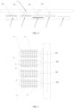
FIG. 2 is a structural schematic diagram of a positive electrode plate-making system of a bag-making type stacking apparatus provided in embodiments of the present application; -
FIG. 3 is a structural schematic diagram of a bag-making type stacking apparatus provided in embodiments of the present application; -
FIG. 4 is a structural schematic diagram of a carrying device of a bag-making type stacking apparatus provided in embodiments of the present application; -
FIG. 5 is a structural schematic diagram of a carrying mechanism provided in the present application; -
FIG. 6 is a structural schematic diagram of a stacked product provided in embodiments of the present application; -
FIG. 7 is an enlarged schematic diagram of point A inFIG. 6 ; -
FIG. 8 is a structural schematic diagram of a carrying device provided in embodiments of the present application; -
FIG. 9 is another view of a carrying device provided in embodiments of the present application; -
FIG. 10 is a structural schematic diagram of a stacking device provided in embodiments of the present application; -
FIG. 11 is a schematic diagram of part of the structure of a carrying device provided in embodiments of the present application; -
FIG. 12 is a structural schematic diagram of a first deviation correcting device provided in embodiments of the present application; -
FIG. 13 is an enlarged schematic diagram of point B inFIG. 12 . - Reference numerals: 1 - negative electrode plate-making system, 101 - negative electrode blanking roll, 102 - first cutting device, 103 - first roll shaft, 2 - unit plate composite bag-making system, 201 - first diaphragm blanking roll, 202 - first diaphragm, 203 - second diaphragm blanking roll, 204 - second diaphragm, 205 - composite roll shaft, 206 - second cutting device, 207 - first detection device, 208 - negative electrode bag-making conveying device, 209 - clamping roll, 3 - positive electrode plate-making system, 301 - positive electrode blanking roll, 302 - third cutting device, 303 - second detection device, 304 - positive electrode plate conveying device, 4 - stacking device, 401 - fixing bottom frame, 402 - fixing plate, 403 - driving device, 404 - supporting plate, 405 - guiding member, 406 - pressing blade, 407 - first fixing plate, 408 - second fixing plate, 409 - first screw, 410 - first sliding block, 411 - second screw, 412 - second sliding block, 413 - rising and descending module, 414 - third fixing plate, 415 - adsorption plate, 5 - carrying device, 501 - first carrying member, 502 - second carrying member, 503 - third carrying member, 504 - fourth carrying member, 505 - fixing frame, 506 - multi-actor linear motor, 507 - first bracket, 508 - driving member, 509 - buffer member, 510 - second bracket, 6 - suction plate, 7 - first deviation correcting device, 701 - fixing bracket, 702 - suction disk, 703 - first driving motor, 704 - second driving motor, 705 - third driving motor, 706 - identification device, 8 - second deviation correcting device, a - first direction, b - second direction, 100 - unit plate, 200 - positive electrode plate, 300 - negative electrode coil, 400 - positive electrode coil, 500 - negative electrode plate.
- Technical solutions of the present application will be described clearly and completely below in combination with the accompanying drawings. Apparently, the described embodiments are merely a part but not all of the embodiments of the present application.
- The components of the embodiments of the present application which are typically described and displayed in the accompanying drawings herein can be arranged and designed in various different configurations. Therefore, the following detailed description of the embodiments of the present application provided in the accompanying drawings is not intended to limit the scope of the claimed application, but only to represent the selected embodiments of the present application.
- Based on the embodiments of the present application, all the other embodiments obtained by those skilled in the art without any creative effort shall all fall within the protection scope of the present application.
- In the description of the present application, it should be noted that, the orientation or position relationship indicated by the terms "center", "upper", "lower", "left", "right", "vertical", "horizontal", "inside" and "outside" is the orientation or position relationship shown based on the drawings, which are merely for the convenience of describing the present application and simplifying the description, rather than indicating or implying that the device or element referred to must have a specific orientation, or be constructed and operated in a specific orientation. Therefore, the terms cannot be understood as a limitation of the present application. In addition, the terms "first", "second" and "third" are only for descriptive purpose and cannot be understood as indicating or implying relative importance.
- In the description of the present application, it should be noted that unless otherwise specified and limited, the terms "install", "connected" and "connection" should be understood in a broad sense, for example, the connection can be a fixed connection, a detachable connection, or an integrated connection; the connection can be a mechanical connection or an electrical connection; the connection can be direct connection, indirect connection through an intermediate medium, or internal communication between two elements. For those skilled in the art, specific meanings of the above terms in the present application can be understood based on specific circumstances.
- The bag-making type stacking apparatus and the stacked product of the embodiments of the present application will be described below with reference to
FIG. 1 to FIG. 13 . - With reference to
FIGs. 1 to 13 , Embodiment I of the present application provides a bag-making type stacking apparatus, including: a negative electrode bag-making system, a positive electrode plate-makingsystem 3, a stackingdevice 4 and a carryingdevice 5, the negative electrode bag-making system is configured to manufacture thenegative electrode plate 500 into aunit plate 100 which is encapsulated in an upper and a lower layer of diaphragms to form a bag structure, the carryingdevice 5 carries thepositive electrode plate 200 and theunit plate 100 to the stackingdevice 4 and stacks on the stackingdevice 4, to obtain a battery cell arranged in an order of "diaphragm, negative electrode, diaphragm, positive electrode, diaphragm, negative electrode, diaphragm, positive electrode", and specific structures and working principles of each system of the bag-making type stacking apparatus will be introduced specifically below. - The negative electrode bag-making system includes a negative electrode plate-making
system 1 and a unit plate composite bag-makingsystem 2, wherein the negative electrode plate-makingsystem 1 includes a negativeelectrode blanking roll 101, afirst roll shaft 103 and afirst cutting device 102 which are arranged sequentially, the negativeelectrode blanking roll 101 is wound with anegative electrode coil 300, and thenegative electrode coil 300 has a sheet-like structure as a whole. - Preferably, the
first cutting device 102 is arranged between the negativeelectrode blanking roll 101 and the unit plate composite bag-makingsystem 2, preferably, thefirst cutting device 102 is arranged to be close to the unit plate composite bag-makingsystem 2, thefirst cutting device 102 includes an upper and a lower blade, thenegative electrode coil 300 penetrates between the upper and lower blades, when the two blades are close to each other, the two blades can cut off thenegative electrode coil 300, and thefirst cutting device 102 cuts periodically according to a preset decision, so as to cut the sheet-shapednegative electrode coil 300 into a plurality ofnegative electrode plates 500 which are spaced apart with the same specification, and under the effect of the subsequent unit plate composite bag-makingsystem 2, thenegative electrode plates 500 after cutting can be conveyed to the unit plate composite bag-makingsystem 2. Wherein thenegative electrode plate 500 includes a current collector and the current collector is uniformly coated with active substances, the current collector of thenegative electrode plate 500 can include but is not limited to copper foil and carbon coated copper foil, and active substances coated on the current collector of thenegative electrode plate 500 includes at least one of graphite material and a composite material of graphite and silica (such as silica carbon). - Preferably, the negative electrode plate-making
system 1 further includes afirst roll shaft 103, thefirst roll shaft 103 is arranged between the negativeelectrode blanking roll 101 and thefirst cutting device 102, and thefirst roll shaft 103 can enable smooth conveying of thenegative electrode coil 300, can change the advancing direction of thenegative electrode coil 300, and can ensure the tightening effect of thenegative electrode coil 300. - Preferably, the unit plate composite bag-making
system 2 includes a firstdiaphragm blanking roll 201, a seconddiaphragm blanking roll 203 and acomposite roll shaft 205, thecomposite roll shaft 205 can be a hot compression roll in the prior art, the firstdiaphragm blanking roll 201 and the seconddiaphragm blanking roll 203 are symmetrically arranged at an upper and a lower side of thenegative electrode coil 300, respectively, the firstdiaphragm blanking roll 201 is wound with afirst diaphragm 202, the seconddiaphragm blanking roll 203 is wound with asecond diaphragm 204, and each end, which extends freely relative to the firstdiaphragm blanking roll 201 and the seconddiaphragm blanking roll 203, of thefirst diaphragm 202 and thesecond diaphragm 204 passes through thecomposite roll shaft 205. - The
composite roll shaft 205 includes an upper roll shaft and a lower roll shaft, an application channel is formed between the upper roll shaft and the lower roll shaft, thenegative electrode plate 500 which is cut to be shaped, thefirst diaphragm 202 and thesecond diaphragm 204 pass through the application channel simultaneously, moreover, thefirst diaphragm 202 is located on an upper surface of thenegative electrode plate 500, thesecond diaphragm 204 is located on a lower surface of thenegative electrode plate 500, under the hot compression effect of thecomposite roll shaft 205, thefirst diaphragm 202 is attached to the upper surface of the plurality of electrode plates, thesecond diaphragm 204 is attached to the lower surface of the plurality of electrode plates, such that the plurality ofnegative electrode plates 500 which are spaced apart are separated and encapsulated as a whole by thefirst diaphragm 202 and thesecond diaphragm 204. - Preferably, the unit plate composite bag-making
system 2 further includes asecond cutting device 206, afirst detection device 207 and a negative electrode bag-making conveyingdevice 208. In the plurality of encapsulatednegative electrode plates 500, part of thefirst diaphragm 202 and thesecond diaphragm 204 between two adjacentnegative electrode plates 500 are bonded, along with continuous operation of each roll shaft, the plurality ofnegative electrode plates 500 after encapsulation gradually pass through thesecond cutting device 206, thesecond cutting device 206 also includes an upper and a lower blade, preferably an electro-thermal blade, moreover, the upper and lower electro-thermal blades of thesecond cutting device 206 enable thesecond cutting device 206 to cut at the position in which thefirst diaphragm 202 is bonded with thesecond diaphragm 204 and enable the cutting position to be subjected to thermoplastic sealing while the cutting position is heated and fractured, such that a plurality of continuously encapsulatednegative electrode plates 500 form a plurality of independently encapsulatedunit plates 100, that is, theunit plate 100 includes anegative electrode plate 500 and an diaphragm (afirst diaphragm 202 and a second diaphragm 204) covering thenegative electrode plate 500, wherein the diaphragm is formed by a base film and a polymer coated on the surface of the base film, The base film has good tensile and tear resistance properties as well as thermal stability. The polymer has strong adhesion and ion conductivity. Among them, the base film can be made of polypropylene or polyethylene, and the polymer can include but is not limited to ceramics, acrylic ester, acrylic ammonium, acrylic sodium, CMC, polyvinylidene fluoride and carboxymethylcellulose sodium. During the process of thermoplastic sealing on both sides of thenegative electrode plate 500, the upper and lower diaphragms can be automatically tensioned, thereby further effectively avoiding the formation of wrinkles on the upper and lower surfaces of thenegative electrode plate 500 while thefirst diaphragm 202 and thesecond diaphragm 204 remain in a tensioned state. - Preferably, the diaphragm and the
negative electrode plate 500 can be bonded together through methods such as hot melting, static electricity and compressive combination, to ensure the bonding effect and tightness between the diaphragm and thenegative electrode plate 500. Ideally, the length, width and other sizes of the diaphragm are greater than those of thenegative electrode plate 500 to ensure the covering effect of the diaphragm on thenegative electrode plate 500. - Preferably, a clamping
roll 209 is arranged between thefirst cutting device 102 and thecomposite roll shaft 205, such that the clampingroll 209 can clamp thenegative electrode plate 500 at the first time after thefirst cutting device 102 cuts off thenegative electrode coil 300 to obtain thenegative electrode plate 500, preferably, the crack of the clampingroll 209 and the application channel are at the same horizontal line, to improve the centering effect between thenegative electrode plate 500 and thecomposite roll shaft 205, and ensure smooth conveyance of thenegative electrode plate 500 to thecomposite roll shaft 205. - Preferably, the
first detection device 207 is preferably a visual detection device, and can be a CCD camera, a detection head of thefirst detection device 207 faces towards asingle unit plate 100 after encapsulation, to detect encapsulation quality and existence of wrinkles on the upper and lower surfaces, preferably, a rejection device is arranged between thefirst detection device 207 and the negative electrode plate bag-making conveyingdevice 208, the rejection device can include but is not limited to a mechanical hand, defective products detected by thefirst detection device 207 are rejected by the rejection device, and qualified products are conveyed to the next process by the negative electrode bag-making conveyingdevice 208. - Preferably, the positive electrode plate-making
system 3 includes apositive blanking roll 301, athird cutting device 302, asecond detection device 303 and a positive electrodeplate conveying device 304, thepositive blanking roll 301 is wound with a sheet-shapedpositive coil 400, one end, freely extending relative to thepositive blanking roll 301, of thepositive coil 400 extends towards thethird cutting device 302 and is clamped by thethird cutting device 302, thethird cutting device 302 has the same structure as thefirst cutting device 102, and has an upper and a lower blade, when the upper and lower blades are close to each other to perform the cutting operation, the sheet-shapedpositive coil 400 can be cut off to obtain a plurality ofpositive electrode plates 200, subsequently, the plurality ofpositive electrode plates 200 are detected by thesecond detection device 303 in sequence, and thesecond detection device 303 is preferably a CCD camera. Wherein thepositive electrode plate 200 includes a current collector and active substances uniformly coated on the current collector, the current collector of thepositive electrode plate 200 includes but is not limited to an aluminum foil and a carbon coated aluminum foil, and the active substance coated on the current collector of thepositive electrode plate 200 includes at least one of the nickel, cobalt and manganese ternary materials (811, 712, 613, etc.), the nickel, cobalt, manganese and aluminum quaternary materials, a cobalt-free material, the lithium iron phosphate material, the lithium manganese iron phosphate material, the sodium ion positive electrode material, etc. It should be noted that, the size of thenegative electrode plate 500 in asingle unit plate 100 is greater than the size of thepositive electrode plate 200, the size of the diaphragm is greater than the size of thenegative electrode plate 500, to ensure that the two layers ofunit plates 100 can completely cover thepositive electrode plates 200 between the two layers ofunit plates 100, and theunit plates 100 and thepositive electrode plates 200 are stacked layer by layer according to this rule, such that a layer ofpositive electrode plates 200 are stacked between any two arbitrary layers ofunit plates 100 to form a battery cell,unit plates 100 are at the outmost layer (that is, the uppermost layer and the lowermost layer) of the battery cell, and theunit plates 100 at the outermost layer can completely cover the adjacentpositive electrode plates 200. - Preferably, a rejection device is also arranged between the
second detection device 303 and the positive electrodeplate conveying device 304, defective products detected by thesecond detection device 303 are rejected by the rejection device, and qualified products detected by thesecond detection device 303 are conveyed to the next process by the positive electrodeplate conveying device 304. - Preferably, the bag-making type stacking apparatus provided in the present application further provides a first
deviation correcting device 7, a seconddeviation correcting device 8, a stackingdevice 4 and a carryingdevice 5, the carryingdevice 5 includes four carrying members which are respectively a first carryingmember 501, a second carryingmember 502, a third carryingmember 503 and a fourth carryingmember 504, a plurality ofsuction plates 6 are arranged on each carrying member, the number of thesuction plates 6 is N, wherein N is a positive integer, preferably, N is greater than 2, and four carrying members move synchronously. - Preferably, the carrying
device 5 further includes a fixingframe 505, the carrying member and the drivingmember 508 are both arranged on the fixingframe 505, specifically, the fixingframe 505 includes a first fixing arm and a second fixing arm arranged to be in parallel with each other, a driving motor is respectively arranged in a sliding manner at the wall surfaces, facing each other mutually, of the first fixing arm and the second fixing arm, the driving motor is preferably a multi-actorlinear motor 506, the multi-actorlinear motor 506 includes a linear sliding rail and a sliding plate which can move relative to the linear sliding rail, the number of the sliding plates on each linear guide rail is the same as the number of the carrying members, preferably, the number of the sliding plates is four, and eight sliding plates are available in total. - Preferably, the carrying member includes a
first bracket 507 and asecond bracket 510 which are arranged symmetrically, wherein thefirst bracket 507 includes a first plate part and a second plate part which are vertical to each other, thesecond bracket 510 includes a third plate part and a fourth plate part which are vertical to each other, the first plate part extends along a vertical direction and is in sliding connection with the sliding plate on the linear guide rail, the second plate part extends along a horizontal direction, the second plate part is adjacent towards the fourth plate part, the third plate part is arranged facing towards the first plate part, and is in sliding connection with the sliding plate on the linear guide rail. - Preferably, a driving
member 508 is arranged on each sliding plate, the drivingmember 508 can be a driving motor or a cylinder, the drivingmember 508 acts on the first plate part and the third plate part, to drive thefirst bracket 507 and thesecond bracket 510 to rise and descend relative to the first fixing part and the second fixing part, respectively. - Preferably, N/2 connecting plates are respectively arranged below the second plate part and the fourth plate part, such that N connecting plates in total are arranged below the second plate part and the fourth plate part, and one
suction plate 6 is connected to each connecting plate through abuffer member 509, thesuction plate 6 is provided with a plurality of air holes, during operation, the air hole is pumped to move to the lower surface of thesuction plate 6 to form a negative pressure, such that thesuction plate 6 can adsorb theunit plate 100 or thepositive electrode plate 200. - Preferably, the carrying
device 5 further includes a vacuum generator (not shown in the figure), the vacuum generator is provided with an air exhaust opening, the air exhaust opening is communicated with the air hole on thesuction plate 6 of the carrying member, to form a negative pressure on the lower surface of thesuction plate 6. - Preferably, the number of the
buffer members 509 is multiple, eachbuffer member 509 includes a plurality of linear bearings which penetrate through the connecting plate, one end of the linear bearing penetrates through the connecting plate or penetrates through the connecting plate and is located on the lower surface of the connecting plate and is provided with a spring, such that buffer can occur when thesuction plate 6 moves downwards to adsorb theunit plate 100 or thepositive electrode plate 200, to avoid adsorbing theunit plate 100 or thepositive electrode plate 200. - Each carrying member is provided with a plurality of
suction plates 6, such that the carryingdevice 5 can transfer a plurality ofunit plates 100 and a plurality ofpositive electrode plates 200 in one instance, thereby greatly improving the working efficiency of the present bag-making type stacking apparatus, moreover, a plurality ofsuction plates 6 on each carrying member are arranged in sequence along a direction vertical to the carrying direction of the carrying member, the spacing between four carrying members is fixed, that is, the carrying distance of each carrying action is unchanged, when the number of workpieces which can be grabbed by each carrying member in one instance needs to be increased, the number of thesuction plates 6 needs to be increased, moreover, the carrying distance of each carrying member does not need to be adjusted, the working efficiency can be improved easily without improving and adjusting the structure of the present bag-making type stacking apparatus, therefore, the present bag-making type stacking apparatus has strong convenience and practicability. - Preferably, the stacking device 4 includes a fixing bottom frame 401, the fixing bottom frame 401 is provided with a fixing plate 402, the fixing plate 402 is provided with a driving device 403, the driving device 403 can be a motor, of course, the driving motor 403 is not limited hereto, the driving device 403 is provided with a driving shaft, the driving shaft penetrates through the fixing plate 402 and is located above the fixing plate 402, moreover, the driving shaft is connected with a supporting plate 404, the supporting plate 404 is provided with N adsorption plates 415 configured to adsorb to fix the positive electrode plates 200 or the unit plates 100, the adsorption plate 415 can rise and descend along with the supporting plate 404 under the effect of the driving device 403, such that when a stacking operation is performed, the carrying device 5 carries N positive electrode plates 200 (or unit plates 100) and places on the adsorption plate 415 to be stacked with the unit plates 100 (or the positive electrode plates 200) on the adsorption plate 415, the driving device 403 can drive the adsorption plate 415 to rise to be aligned with and be in contact with the positive electrode plates 200 (or the unit plates 100) on the carrying device 5, subsequently, one stacking is completed after the carrying device 5 releases the positive electrode plates 200 (or the unit plates 100), and so on.
- Preferably, a guiding
member 405 is connected to the upper surface of the fixingplate 402, preferably, the number of the guidingmembers 405 is two groups, the two groups of guidingmembers 405 are symmetrically arranged at two sides of the driving shaft, respectively, the guidingmember 405 includes a guiding sleeve and a linear bearing, the guiding sleeve is arranged on an upper surface of the fixingplate 402, and one end of the linear bearing is arranged at the other end of the guiding shaft of the guiding sleeve and is connected to a bottom wall surface of the supportingplate 404. - Preferably, the stacking device 4 further includes a pressing blade 406 and a driving module configured to drive the pressing blade 406 to rise or descend and open or close, the stacking device 4 further includes a first fixing plate 407 and a second fixing plate 408 configured to fix the pressing blade 406, two sides, arranged along a length direction of the positive electrode plate 200 or the unit plate 100, of the first fixing plate 407 and the second fixing plate 408 are respectively vertically arranged upwards, the first fixing plate 407 is taken as an example for illustration, N protrusions are formed at intervals along the length direction of the long side of the first fixing plate 407, an inner wall surface of each protrusion is provided with a cylinder, an output part of the cylinder is provided with a sliding rail, a sliding block connected with the sliding rail is arranged at the tail part of the pressing blade 406, a head end, relative to a tail end, of the pressing blade 406 extends towards the second fixing plate 408, such that the pressing blade 406 can be located above the positive electrode plate 200 or the unit plate 100, moreover, the pressing blade 406 can slide left and right in the length direction of the first fixing plate 407 to adjust the position of the pressing blade 406 relative to the positive electrode plate 200 or the unit plate 100. The
second fixing plate 408 is in a similar way, N pressing blades on thesecond fixing plate 408 extend towards thefirst fixing plate 407 and can move left and right along a length direction of thesecond fixing plate 408, which will be understood by those skilled in the art, and will not be repeated redundantly herein. - The driving module includes an opening and closing module and a rising and descending
module 413, the opening and closing module includes a first driving member and a second driving member, the first driving member includes afirst screw 409, a first slidingblock 410 and a first driving piece configured to drive thefirst screw 409 to rotate, the first slidingblock 410 is connected with thefirst fixing plate 407, after the first driving screw rotates, the first slidingblock 410 drives thefirst fixing plate 407 to move along the length direction of the positive electrode plate 200 (or the unit plate 100), such that thepressing blade 406 on thefirst fixing plate 407 can be close to or away from the positive electrode plate 200 (or the unit plate 100), similarly, the second driving member includes asecond screw 411, a second slidingblock 412 and a second driving piece configured to drive thesecond screw 411 to rotate, the second slidingblock 412 is connected to thesecond fixing plate 408, to drive thesecond fixing plate 408 and thepressing blade 406 on thesecond fixing plate 408 to be relatively close to or away from the positive electrode plate 200 (or the unit plate 100). - Preferably, the rotational direction of the first screw is opposite to the rotational direction of the
second screw 411, such that the two moves to be close to or away from each other, to realize opening and closing actions of thepressing blade 406 on thefirst fixing plate 407 and thepressing blade 406 on thesecond fixing plate 408. - The rising and descending
module 413 includes a third driving member and a fourth driving member, wherein the third driving member includes athird fixing plate 414 and a third driving piece, the fourth driving member includes afourth fixing plate 402 and a fourth driving piece, thethird fixing plate 414 and thethird fixing plate 414 are arranged to face each other and extend along a length direction of the positive electrode plate 200 (or the unit plate 100), thethird fixing plate 414 and thefourth fixing plate 402 are respectively connected with thefirst fixing plate 407 and thesecond fixing plate 408, and the third driving piece and the fourth driving piece simultaneously drive thefirst fixing plate 407 and thesecond fixing plate 408 to rise and descend in a vertical direction, such that thepressing blade 406 can rise and descend relative to the positive electrode plate 200 (or the unit plate 100). - Through opening or closing and rising or descending of the double rows of
pressing blades 406, the positive electrode plate 200 (or the unit plate 100) can be tightened, or in the stacking process, the double rows ofpressing blades 406 are disengaged from the positive electrode plate 200 (or the unit plate 100) to expose the space above the positive electrode plate 200 (or the unit plate 100) to perform the stacking operation. - Preferably, the first deviation correcting device 7 includes N fixing brackets 701 distributed sequentially, N suction discs 702 with a flat plate structure and configured to correspondingly adsorb N positive electrode plates 200 (or unit plates 100), and N groups of adjustment driving members, one suction disc 702 is arranged on each fixing bracket 701, the adjustment driving member includes a first driving motor 703, a second driving motor 704 and a third driving motor 705, the third driving motor 705 is arranged between the first driving motor 703 and the second driving motor 704, the first driving motor 703 is provided with a first driving part, the second driving motor 704 is provided with a second driving part, the third driving motor 705 is provided with a third driving part, and the three driving parts are all connected with the fixing bracket 701, specifically, the driving direction of the first driving motor 703 and the second driving motor is an X direction, the driving direction of the third driving motor 705 is a Y direction, the first driving motor 703 and the second driving motor 704 respectively perform deviation correction on the fixing bracket 701 in the X direction at two ends, and the third driving motor 705 performs deviation correction on the fixing bracket 701 in the Y direction, to adjust an included angle between the X direction and the Y direction, and ensure that N positive electrode plates 200 (or unit plates 100) are distributed along the same straight line and are arranged to be in parallel, moreover, the spacing between two adjacent positive electrode plates 200 (or unit plates 100) is the same, the positive electrode plates 200 (or the unit plates 100) are arranged to be opposite to each other on each suction disc 702, to ensure that the positive electrode plates 200 (or the unit plates 100) can directly correspond to N adsorption plates 415 on the stacking device 4 after the carrying member carries the positive electrode plates 200 (or the unit plates 100) on the suction disc 702 to the stacking device 4, to ensure stacking precision and quality.
- Ideally, a positioning reference is arranged below the
suction disc 702, anidentification device 706 is arranged above the fixingbracket 701, theidentification device 706 can be a CCD camera, a sensor, etc. Theidentification device 706 is configured to detect the deviation between the positive electrode plate 200 (or the unit plate 100) and the positioning reference, the three driving motors of the adjustment driving member are respectively adjusted adaptively according to detection results of theidentification device 706. - For the structure and working principle of the second
deviation correcting device 8, please refer to the firstdeviation correcting device 7, which can be completely understood by those skilled in the art, and will not be repeated redundantly herein. - As shown in
FIG. 3 , the negative electrode bag-making system, the firstdeviation correcting device 7, the stackingdevice 4, the seconddeviation correcting device 8 and the positive electrode plate-makingsystem 3 are sequentially distributed on the same side of the carryingdevice 5 according to the same spacing, specifically speaking, the negative electrode bag-making conveyingdevice 208, the firstdeviation correcting device 7, the stackingdevice 4, the seconddeviation correcting device 8 and the positive electrodeplate conveying device 304 are sequentially distributed along the same side of the carryingdevice 5. - When the carrying device 5 performs a carrying task, an initial state is firstly prepared, for example, the first carrying member 501 is located above the negative electrode bag-making conveying device 208 and is arranged to be opposite to the negative electrode bag-making conveying device 208, the second carrying member 502 is located above the first deviation correcting device 7 and is arranged to be opposite to the first deviation correcting device 7, the third carrying member 503 is located above the stacking device 4 and is arranged to be opposite to the stacking device 4, the fourth carrying member 504 is located above the second deviation correcting device 8 and is arranged to be opposite to the positive electrode plate conveying device 304, at this time, N suction plates 6 of the first carrying member 501 absorb N unit plates 100 on the negative electrode bag-making conveying device 208, the second carrying member 502 absorbs N unit plates 100 on the first deviation correcting device 7, the stacking device 4 is in an unloaded state, the third carrying member 503 is unloaded correspondingly, the fourth carrying member 504 absorbs a plurality of positive electrode plates 200 on the second deviation correcting device 8, subsequently four carrying members simultaneously move by a predetermined spacing towards the first direction a, such that the first carrying member 501 is arranged to be opposite to the first deviation correcting device 7, the second carrying member 502 is arranged to be opposite to the stacking device 4, the third carrying member 503 is opposite to the second deviation correcting device 8, to grab N positive electrode plates 200 on the second deviation correcting device 8, the fourth carrying member 504 is opposite to the positive electrode plate conveying device 304 to absorb N positive electrode plates 200 on the positive electrode plate conveying device 304, subsequently, each carrying member releases its own load, therefore, N unit plates 100 on the negative electrode bag-making conveying device 208 are carried to the first deviation correcting device 7 and N unit plates 100 which are subjected to deviation correction on the first deviation correcting device 7 are carried to the stacking device 4.
- Then four carrying members move by a preset spacing towards a second direction b, such that N
positive electrode plates 200 absorbed by the third carryingmember 503 and subjected to deviation correction by the seconddeviation correcting device 8 are stacked aboveN unit plates 100, the fourth carryingmember 504 places thepositive electrode plates 200 absorbed on the positive electrodeplate conveying device 304 on the seconddeviation correcting device 8 for deviation correction, the four carrying members reciprocate on the stacking device according to the above rule for a stacking operation. - It can be seen that, when the bag-making stacking apparatus provided in the present application is used, a plurality of unit plates and positive electrode plates can be stacked in one instance, to greatly improve the stacking speed and improve the production efficiency, and importantly, the tension change amplitude of a diaphragm is small, and the diaphragm is always kept in a properly tensioned state, in combination with the stacking operation after bag-making and plate making in advance, the probability of the occurrence of wrinkles is almost zero, products obtained from actual processing have no wrinkles, thereby greatly improving the quality of stacking, ensuring safety of the battery, avoiding thermal runaway caused by diaphragm contraction, and ensuring battery safety. In addition, as to the bag-making stacking apparatus provided in the present application, when more plates are stacked, the stacking distance is unchanged, and the stacking efficiency is further quickened.
- As shown in
FIGs. 6 and 7 , Embodiment I of the present application further provides a stacked product, specifically a battery cell product which is processed by the bag-making stacking apparatus provided in the above embodiment. The stacked product obtained from stacking by the bag-making stacking apparatus provided in the above embodiment is stacked from top to bottom according to a rule of one layer ofnegative electrode plates 500 encapsulated in the bag, one layer ofpositive electrode plates 200, one layer ofnegative electrode plates 500 encapsulated in the bag, and one layer ofpositive electrode plates 200, thenegative electrode plates 500 are encapsulated by a diaphragm, such that the upper and lower surfaces of eachnegative electrode plate 500 are respectively coated with afirst diaphragm 202 and asecond diaphragm 204, one surface, deviating from thenegative electrode plate 500, of thefirst diaphragm 202 is bonded with onepositive electrode plate 200, one surface, deviating from thenegative electrode plate 500, of thesecond diaphragm 204 is bonded with anotherpositive electrode plate 200. Compared with traditional Z-shaped stacking manner, the stacked product obtained through bagging thenegative electrode plate 500 in advance and attaching the diaphragm to thepositive electrode plate 200 has no wrinkled diaphragms, thereby avoiding battery shortage caused by wrinkles, moreover,negative electrode plates 500 encapsulated in the bag are at the outermost layer of the stacked product, the size (length, width) of thenegative electrode plate 500 is greater than the size of thepositive electrode plate 200, and the size of the bag outside thenegative electrode plate 500 is also greater than the size of thenegative electrode plate 500, such that the bag can completely cover thenegative electrode plate 500, and thenegative electrode plate 500 can completely cover thepositive electrode plate 200. - Embodiment II of the present application provides another bag-making type stacking apparatus (not shown in the figure). The bag-making type stacking apparatus includes a positive electrode bag-making system, a negative electrode plate-making system, a stacking device and a carrying device, wherein the stacking device and the carrying device in Embodiment II have the same structure and working principle as the stacking device and the carrying device in Embodiment I, specifically speaking, another bag-making stacking apparatus in Embodiment II can be obtained through exchanging the positions of the negative blanking roll and the positive blanking roll and changing the processing manner of "negative electrode bag-making and positive electrode bag-making" into "positive electrode bag-making and negative electrode bag-making" in Embodiment I, as to the setting manner, structure and working principle of the positive electrode bag-making system, the negative electrode plate-making system, the stacking device and the carrying device in the present embodiment, please refer to the content in the above Embodiment I, which can be completely understood by those skilled in the art and will not be repeated redundantly herein.
- In addition, correspondingly, another stacked product (not shown in the figure) obtained through processing by the bag-making type stacking apparatus provided in Embodiment II is stacked from top to bottom according to the rule of one layer of positive electrode plates encapsulated in the bag, one bag of negative electrode plates, one bag of positive electrode plates encapsulated in the bag and one layer of negative electrode plates, the bag of the positive electrode plate is formed through encapsulation by a diaphragm, such that the upper and lower surfaces of each positive electrode plate is respectively coated with a diaphragm, one surface, deviating from the positive electrode plate, of the diaphragm is bonded with the negative electrode plate. Such a stacked product also has the advantage of no existence of wrinkled diaphragms.
- Finally, it should be noted that, each of the above embodiments is merely for illustrating rather than limiting technical solutions of the present application; although the present application has been described in detail with reference to each of the above embodiments, those skilled in the art should understand that, technical solutions recorded in each of the above embodiments can still be modified, or part or all of the technical features can be substituted equivalently, while these modifications or substitutions will not enable the spirit of the corresponding technical solutions to depart from the scope of the technical solutions of each embodiment of the present application.
- The bag-making type stacking apparatus and the stacked product provided in the present application can stack a plurality of unit plates and a plurality of positive electrode plates in one instance, thereby greatly improving the stacking speed, and improving the production efficiency; and importantly, the tension change amplitude of a diaphragm is small, and the diaphragm is always kept in a properly tensioned state, in combination with the stacking operation after bag-making and plate making in advance, the probability of the occurrence of wrinkles is almost zero, thereby greatly improving the quality of stacking, and ensuring safety of the battery.
Claims (18)
- A bag-making type stacking apparatus, comprising:a negative electrode bag-making system, comprising a negative electrode plate-making system and a unit plate composite bag-making system, which are arranged in a spaced manner;a positive electrode plate-making system which is spaced apart from the negative electrode bag-making system;a stacking device, which is spaced apart from the negative electrode bag-making system and the positive electrode plate-making system; anda carrying device which is spaced apart from the stacking device, the carrying device being provided with a carrying member, wherein the carrying member reciprocates between the unit plate composite bag-making system, the stacking device and the positive electrode plate-making system.
- The bag-making type stacking apparatus of claim 1, wherein the negative electrode plate-making system comprises:a negative electrode blanking roll wound with negative electrode coils;a first cutting device arranged between the negative electrode blanking roll and the unit plate composite bag-making system, wherein the first cutting device is configured to cut the negative electrode coils into negative electrode plates, and the unit plate composite bag-making system is configured to produce unit plates;the negative electrode plate comprises a current collector coated with active substances, wherein the unit plate contains the negative electrode plate and an diaphragm covering the negative electrode plate; the diaphragm covers the negative electrode plate; and the diaphragm contains a base film and a polymer coated on the surface of the base film; anda first roll shaft arranged between the negative electrode blanking roll and the first cutting device.
- The bag-making type stacking apparatus of claim 2, wherein the unit plate composite bag-making system comprises:a first diaphragm blanking roll wound with a first diaphragm;a second diaphragm blanking roll arranged to be symmetrical to the first diaphragm blanking roll and wound with a second diaphragm; anda composite roll shaft formed with an application channel, wherein the negative electrode plate, the first diaphragm and the second diaphragm pass through the application channel, and the negative electrode plate is located between the first diaphragm and the second diaphragm.
- The bag-making type stacking apparatus of claim 3, wherein the unit plate composite bag-making system further comprises a second cutting device which is spaced apart from the composite roll shaft in an advancing direction of the negative electrode plate, and the second cutting device is configured to cut off the first diaphragm and the second diaphragm arranged between any two arbitrary adjacent negative electrode plates.
- The bag-making type stacking apparatus of claim 4, wherein the unit plate composite bag-making system further comprises:a first detection device;a negative electrode bag-making conveying device, wherein the second cutting device, the first detection device and the negative electrode bag-making conveying device are arranged at intervals in the advancing direction of the electrode negative electrode plate.
- The bag-making type stacking apparatus of claim 5, wherein the positive electrode plate-making system comprises:a positive electrode blanking roll wound with positive electrode coils; anda third cutting device arranged at intervals with the positive electrode blanking roll in an advancing direction of the positive electrode coils and configured to cut the positive electrode coils into positive electrode plates, wherein the positive electrode plate comprises the current collector and the active substances coated on the current collector, and the unit plate covers the positive electrode plate.
- The bag-making type stacking apparatus of claim 6, wherein the positive electrode plate-making system further comprises:a second detection device; anda positive electrode plate conveying device, wherein the third cutting device, the second detection device and the positive electrode plate conveying device are sequentially arranged at intervals in the advancing direction of the positive electrode plate.
- The bag-making type stacking apparatus of claim 7, wherein the bag-making type stacking apparatus further comprises:a first deviation correcting device which is spaced apart from the negative electrode bag-making conveying device;a second deviation correcting device which is spaced apart from the positive electrode plate conveying device; andthe first deviation correcting device and the second deviation correcting device are located between the negative electrode bag-making conveying device and the positive electrode plate conveying device.
- The bag-making type stacking apparatus of claim 8, wherein the bag-making type stacking apparatus further comprises:the stacking device is arranged between the first deviation correcting device and the second deviation correcting device, the stacking device is configured to stack the unit plates and the positive electrode plates layer by layer to form a battery cell, the positive electrode plates are arranged between two adjacent layers of the unit plates; and the unit plates are at an outermost layer of the battery cell; andthe negative electrode bag-making conveying device, the first deviation correcting device, the stacking device, the second deviation correcting device and the positive electrode plate conveying device are arranged sequentially at the same predetermined intervals.
- The bag-making type stacking apparatus of claim 9, wherein the carrying device comprises four carrying members which move synchronously;the carrying device has a first working position and a second working position, and the carrying device reciprocates between the first working position and the second working position;in the first working position, the four carrying members are respectively arranged facing the negative electrode bag-making conveying device, the first deviation correcting device, the stacking device and the second deviation correcting device; andin the second working position, the four carrying members are respectively arranged facing the first deviation correcting device, the stacking device, the second deviation correcting device and the positive electrode plate conveying device.
- The bag-making type stacking apparatus of claim 10, wherein the carrying member comprises:a bracket;a plurality of suction plates arranged sequentially on the bracket, wherein the suction plate is formed with an adsorption surface; anda driving member arranged on the bracket, wherein the bracket is connected with the driving member, and the driving member is configured to drive the bracket and the suction plate to be close to or away from the first deviation correcting device, the stacking device, the second deviation correcting device or the positive electrode plate conveying device.
- The bag-making type stacking apparatus of claim 11, wherein the carrying member further comprises a buffer member arranged between the bracket and the suction plate.
- The bag-making type stacking apparatus of claim 9, wherein the stacking device comprises:a fixing bottom frame;a driving device arranged on the fixing bottom frame and provided with a driving shaft;a support member connected with the driving shaft; anda plurality of adsorption plates arranged on the support member.
- The bag-making type stacking apparatus of claim 13, wherein the stacking device further comprises:a first fixing plate and a second fixing plate arranged facing each other, wherein the support member is arranged between the first fixing plate and the second fixing plate;a plurality of pressing blades arranged on the first fixing plate and the second fixing plate and arranged facing the adsorption plate; anda driving module connected with the first fixing plate and the second fixing plate and capable of driving the first fixing plate and the second fixing plate to be close to or away from each other.
- The bag-making type stacking apparatus of claim 8, wherein the first deviation correcting device comprises:a plurality of fixing brackets arranged at intervals;a plurality of suction disks, wherein each of the fixing brackets is provided with one of the suction disks;an adjustment driving member provided with a driving part, wherein the driving part is connected with the fixing bracket; andan identification device arranged above the suction disk and arranged facing towards the suction disk.
- A stacked product manufactured by the bag-making type stacking apparatus of any one of claims 1-15, wherein
the stacked product comprises a plurality of negative electrode plates and a plurality of positive electrode plates encapsulated inside a bag, one of the positive electrode plates is arranged between any two arbitrary negative electrode plates encapsulated inside the bag; and the negative electrode plates encapsulated in the bag are at the outermost layer of the stacked product. - A bag-making type stacking apparatus, comprising:a positive electrode bag-making system, comprising a positive electrode plate-making system and a unit plate composite bag-making system, which are arranged in a spaced manner;a negative electrode plate-making system which is spaced apart from the positive electrode bag-making system;a stacking device, which is spaced apart from the positive electrode bag-making system and the negative electrode plate-making system; anda carrying device which is spaced apart from the stacking device, the carrying device being provided with a carrying member, wherein the carrying member reciprocates between the unit plate composite bag-making system, the stacking device and the negative electrode plate-making system.
- The bag-making type stacking apparatus of claim 17, wherein the positive electrode plate-making system is configured to produce positive electrode plates, the positive electrode plate comprises a current collector and active substances coated on the current collector, the unit plate composite bag-making system is configured to produce unit plates, the unit plate comprises the positive electrode plate and an diaphragm covering the positive electrode plate, and the diaphragm covers the positive electrode plate;the negative electrode plate-making system is configured to produce negative electrode plates, the negative electrode plate comprises a current collector and active substances coated on the current collector, and the unit plate covers the negative electrode plate; andthe stacking device is configured to stack the unit plates and the negative electrode plates layer by layer to form a battery cell, the negative electrode plates are arranged between two adjacent layers of the unit plates, and the unit plates are at the outermost layer of the battery cell.
Applications Claiming Priority (2)
| Application Number | Priority Date | Filing Date | Title |
|---|---|---|---|
| CN202123075424.9U CN216698467U (en) | 2021-12-08 | 2021-12-08 | Bag-making type lamination equipment and lamination product |
| PCT/CN2022/073022 WO2023103155A1 (en) | 2021-12-08 | 2022-01-20 | Bag-making type stacking apparatus and stacked product |
Publications (2)
| Publication Number | Publication Date |
|---|---|
| EP4394993A1 true EP4394993A1 (en) | 2024-07-03 |
| EP4394993A4 EP4394993A4 (en) | 2025-01-15 |
Family
ID=81837692
Family Applications (1)
| Application Number | Title | Priority Date | Filing Date |
|---|---|---|---|
| EP22902600.0A Pending EP4394993A4 (en) | 2021-12-08 | 2022-01-20 | BAG-MAKING TYPE STACKING APPARATUS AND STACKED PRODUCT |
Country Status (5)
| Country | Link |
|---|---|
| US (1) | US20250006973A1 (en) |
| EP (1) | EP4394993A4 (en) |
| KR (1) | KR20240091156A (en) |
| CN (1) | CN216698467U (en) |
| WO (1) | WO2023103155A1 (en) |
Family Cites Families (9)
| Publication number | Priority date | Publication date | Assignee | Title |
|---|---|---|---|---|
| JP4713373B2 (en) * | 2006-03-10 | 2011-06-29 | リッセル株式会社 | Lithium ion battery and method and apparatus for manufacturing the same |
| JP5110632B2 (en) * | 2007-05-14 | 2012-12-26 | Necトーキン株式会社 | Manufacturing method of laminated battery and manufacturing apparatus thereof |
| CN101752607B (en) * | 2010-01-18 | 2012-05-02 | 深圳市吉阳自动化科技有限公司 | A preparation method and system for a lithium-ion battery core pack |
| JP2012199210A (en) * | 2011-03-23 | 2012-10-18 | Ihi Corp | Production apparatus and production method of electrode laminate |
| JP6142525B2 (en) * | 2012-12-25 | 2017-06-07 | 日産自動車株式会社 | Electrode position detector |
| CN104701577A (en) * | 2015-03-26 | 2015-06-10 | 深圳市吉阳自动化科技有限公司 | Lamination battery cell preparing system and preparing method thereof |
| CN107508002B (en) * | 2017-08-11 | 2019-11-15 | 深圳市格林晟科技有限公司 | A cutting and stacking machine |
| CN113394440B (en) * | 2020-12-28 | 2024-12-03 | 深圳市格林晟科技股份有限公司 | A lamination device and control method thereof |
| CN112768744B (en) * | 2021-01-21 | 2022-10-04 | 深圳市科瑞新能源装备技术有限公司 | Battery manufacturing apparatus |
-
2021
- 2021-12-08 CN CN202123075424.9U patent/CN216698467U/en active Active
-
2022
- 2022-01-20 US US18/707,437 patent/US20250006973A1/en active Pending
- 2022-01-20 KR KR1020247017887A patent/KR20240091156A/en active Pending
- 2022-01-20 WO PCT/CN2022/073022 patent/WO2023103155A1/en not_active Ceased
- 2022-01-20 EP EP22902600.0A patent/EP4394993A4/en active Pending
Also Published As
| Publication number | Publication date |
|---|---|
| CN216698467U (en) | 2022-06-07 |
| WO2023103155A1 (en) | 2023-06-15 |
| KR20240091156A (en) | 2024-06-21 |
| US20250006973A1 (en) | 2025-01-02 |
| EP4394993A4 (en) | 2025-01-15 |
Similar Documents
| Publication | Publication Date | Title |
|---|---|---|
| CN1200474C (en) | Packaging apparatus for secondary lithium cell automatic production system | |
| CN112838260B (en) | Lamination device | |
| CN218039382U (en) | Lamination platform and lamination equipment | |
| CN205583074U (en) | Cell winding lamination machine | |
| CN105789678B (en) | Cell winding lamination machine is with going up piece device | |
| CN113517465A (en) | Lamination equipment, battery cell and preparation method of battery cell | |
| CN211879535U (en) | Heat sealing mechanism and composite material belt forming device | |
| KR101040704B1 (en) | Stacker for Secondary Battery | |
| CN106159336B (en) | Lamination machine for laminated lithium ion winding core | |
| CN116914273A (en) | Method and system for manufacturing anode continuous solid-state battery and solid-state battery | |
| CN112635809A (en) | Battery pole piece lamination equipment and battery core lamination method | |
| CN205583044U (en) | Loading device for cell winding and stacking machine | |
| CN105742720A (en) | Winding device for cell winding lamination machine | |
| CN117577956B (en) | Lamination device and method | |
| JP6702079B2 (en) | Laminated electrode manufacturing apparatus and laminated electrode manufacturing method | |
| CN221080091U (en) | Continuous lamination machine | |
| CN211654975U (en) | Lithium-sulfur battery bag-making and laminating device | |
| CN1387276A (en) | Laminating apparatus for automatic secondary lithium cell production system | |
| EP4394993A1 (en) | Bag-making type stacking apparatus and stacked product | |
| JP5831488B2 (en) | Battery resin sheet processing apparatus and processing method | |
| CN216966414U (en) | A high-speed slicing device and lamination equipment | |
| CN217522093U (en) | Electrode assembly preparation device | |
| CN112909349A (en) | Multi-station die stacking method | |
| CN205583073U (en) | Winding device for cell winding lamination machine | |
| CN111584922A (en) | Automatic production equipment for railway battery cell module |
Legal Events
| Date | Code | Title | Description |
|---|---|---|---|
| STAA | Information on the status of an ep patent application or granted ep patent |
Free format text: STATUS: THE INTERNATIONAL PUBLICATION HAS BEEN MADE |
|
| PUAI | Public reference made under article 153(3) epc to a published international application that has entered the european phase |
Free format text: ORIGINAL CODE: 0009012 |
|
| STAA | Information on the status of an ep patent application or granted ep patent |
Free format text: STATUS: REQUEST FOR EXAMINATION WAS MADE |
|
| 17P | Request for examination filed |
Effective date: 20240327 |
|
| AK | Designated contracting states |
Kind code of ref document: A1 Designated state(s): AL AT BE BG CH CY CZ DE DK EE ES FI FR GB GR HR HU IE IS IT LI LT LU LV MC MK MT NL NO PL PT RO RS SE SI SK SM TR |
|
| REG | Reference to a national code |
Ref country code: DE Ref legal event code: R079 Free format text: PREVIOUS MAIN CLASS: H01M0010058000 Ipc: B65H0029320000 |
|
| A4 | Supplementary search report drawn up and despatched |
Effective date: 20241212 |
|
| RIC1 | Information provided on ipc code assigned before grant |
Ipc: H01M 10/0525 20100101ALI20241206BHEP Ipc: H01M 10/04 20060101ALI20241206BHEP Ipc: H01M 10/058 20100101ALI20241206BHEP Ipc: H01M 10/0585 20100101ALI20241206BHEP Ipc: H01M 10/0583 20100101ALI20241206BHEP Ipc: B65H 31/26 20060101ALI20241206BHEP Ipc: B65H 31/24 20060101ALI20241206BHEP Ipc: B65H 31/10 20060101ALI20241206BHEP Ipc: B65H 29/32 20060101AFI20241206BHEP |
|
| DAV | Request for validation of the european patent (deleted) | ||
| DAX | Request for extension of the european patent (deleted) |