EP4394963A1 - Cylindrical cell and electronic device - Google Patents
Cylindrical cell and electronic device Download PDFInfo
- Publication number
- EP4394963A1 EP4394963A1 EP23173023.5A EP23173023A EP4394963A1 EP 4394963 A1 EP4394963 A1 EP 4394963A1 EP 23173023 A EP23173023 A EP 23173023A EP 4394963 A1 EP4394963 A1 EP 4394963A1
- Authority
- EP
- European Patent Office
- Prior art keywords
- tab
- electrode assembly
- cylindrical cell
- electrode
- assembly body
- Prior art date
- Legal status (The legal status is an assumption and is not a legal conclusion. Google has not performed a legal analysis and makes no representation as to the accuracy of the status listed.)
- Granted
Links
Images



Classifications
-
- H—ELECTRICITY
- H01—ELECTRIC ELEMENTS
- H01M—PROCESSES OR MEANS, e.g. BATTERIES, FOR THE DIRECT CONVERSION OF CHEMICAL ENERGY INTO ELECTRICAL ENERGY
- H01M50/00—Constructional details or processes of manufacture of the non-active parts of electrochemical cells other than fuel cells, e.g. hybrid cells
- H01M50/50—Current conducting connections for cells or batteries
- H01M50/531—Electrode connections inside a battery casing
- H01M50/533—Electrode connections inside a battery casing characterised by the shape of the leads or tabs
-
- H—ELECTRICITY
- H01—ELECTRIC ELEMENTS
- H01M—PROCESSES OR MEANS, e.g. BATTERIES, FOR THE DIRECT CONVERSION OF CHEMICAL ENERGY INTO ELECTRICAL ENERGY
- H01M10/00—Secondary cells; Manufacture thereof
- H01M10/04—Construction or manufacture in general
- H01M10/0422—Cells or battery with cylindrical casing
-
- H—ELECTRICITY
- H01—ELECTRIC ELEMENTS
- H01M—PROCESSES OR MEANS, e.g. BATTERIES, FOR THE DIRECT CONVERSION OF CHEMICAL ENERGY INTO ELECTRICAL ENERGY
- H01M10/00—Secondary cells; Manufacture thereof
- H01M10/05—Accumulators with non-aqueous electrolyte
- H01M10/058—Construction or manufacture
- H01M10/0587—Construction or manufacture of accumulators having only wound construction elements, i.e. wound positive electrodes, wound negative electrodes and wound separators
-
- H—ELECTRICITY
- H01—ELECTRIC ELEMENTS
- H01M—PROCESSES OR MEANS, e.g. BATTERIES, FOR THE DIRECT CONVERSION OF CHEMICAL ENERGY INTO ELECTRICAL ENERGY
- H01M50/00—Constructional details or processes of manufacture of the non-active parts of electrochemical cells other than fuel cells, e.g. hybrid cells
- H01M50/10—Primary casings; Jackets or wrappings
- H01M50/102—Primary casings; Jackets or wrappings characterised by their shape or physical structure
- H01M50/107—Primary casings; Jackets or wrappings characterised by their shape or physical structure having curved cross-section, e.g. round or elliptic
-
- H—ELECTRICITY
- H01—ELECTRIC ELEMENTS
- H01M—PROCESSES OR MEANS, e.g. BATTERIES, FOR THE DIRECT CONVERSION OF CHEMICAL ENERGY INTO ELECTRICAL ENERGY
- H01M50/00—Constructional details or processes of manufacture of the non-active parts of electrochemical cells other than fuel cells, e.g. hybrid cells
- H01M50/10—Primary casings; Jackets or wrappings
- H01M50/147—Lids or covers
- H01M50/148—Lids or covers characterised by their shape
- H01M50/152—Lids or covers characterised by their shape for cells having curved cross-section, e.g. round or elliptic
-
- H—ELECTRICITY
- H01—ELECTRIC ELEMENTS
- H01M—PROCESSES OR MEANS, e.g. BATTERIES, FOR THE DIRECT CONVERSION OF CHEMICAL ENERGY INTO ELECTRICAL ENERGY
- H01M50/00—Constructional details or processes of manufacture of the non-active parts of electrochemical cells other than fuel cells, e.g. hybrid cells
- H01M50/10—Primary casings; Jackets or wrappings
- H01M50/172—Arrangements of electric connectors penetrating the casing
- H01M50/174—Arrangements of electric connectors penetrating the casing adapted for the shape of the cells
- H01M50/179—Arrangements of electric connectors penetrating the casing adapted for the shape of the cells for cells having curved cross-section, e.g. round or elliptic
-
- H—ELECTRICITY
- H01—ELECTRIC ELEMENTS
- H01M—PROCESSES OR MEANS, e.g. BATTERIES, FOR THE DIRECT CONVERSION OF CHEMICAL ENERGY INTO ELECTRICAL ENERGY
- H01M50/00—Constructional details or processes of manufacture of the non-active parts of electrochemical cells other than fuel cells, e.g. hybrid cells
- H01M50/60—Arrangements or processes for filling or topping-up with liquids; Arrangements or processes for draining liquids from casings
- H01M50/609—Arrangements or processes for filling with liquid, e.g. electrolytes
- H01M50/627—Filling ports
-
- Y—GENERAL TAGGING OF NEW TECHNOLOGICAL DEVELOPMENTS; GENERAL TAGGING OF CROSS-SECTIONAL TECHNOLOGIES SPANNING OVER SEVERAL SECTIONS OF THE IPC; TECHNICAL SUBJECTS COVERED BY FORMER USPC CROSS-REFERENCE ART COLLECTIONS [XRACs] AND DIGESTS
- Y02—TECHNOLOGIES OR APPLICATIONS FOR MITIGATION OR ADAPTATION AGAINST CLIMATE CHANGE
- Y02E—REDUCTION OF GREENHOUSE GAS [GHG] EMISSIONS, RELATED TO ENERGY GENERATION, TRANSMISSION OR DISTRIBUTION
- Y02E60/00—Enabling technologies; Technologies with a potential or indirect contribution to GHG emissions mitigation
- Y02E60/10—Energy storage using batteries
Definitions
- the area of the first tab region is S1
- the area of the end portion of the electrode assembly body is S0
- the ratio of S1 to S0 is in the range of 0.3 to 0.5.
- the cylindrical cell further includes a connecting piece, and the connecting piece is arranged between the electrode pole and the first tab to electrically connect the electrode pole and the first tab.
- the orthographic projection area of the connecting piece on the first end of the electrode assembly body is S2, and S2 ⁇ S1.
- the cylindrical cell further includes a cover plate, and the cover plate is fixed to one end of the surrounding wall away from the end wall.
- the number of turns of the electrode assembly body is N, with the innermost turn being the first turn, and the outermost turn being the Nth turn, the second tab region is located between 1/2 N turns and N turns of the electrode assembly body.
- the cylindrical cell provided by the present disclosure includes a housing, which includes an end wall and a surrounding wall enclosing the end wall; an electrode pole, which penetrates through the end wall and is connected to the end wall in an insulated manner; and a electrode assembly, which is arranged in the housing, and the electrode assembly includes a electrode assembly body and a first tab, the first tab is located at the first end of the electrode assembly body facing the electrode pole, the orthographic projection of the first tab on the first end of the electrode assembly body is the first tab region, and the distance between any point on the outer boundary of the first tab region and the inner side of the surrounding wall is L1, a radius of the inner side of the surrounding wall is R0, and the ratio of L1 to R0 ranges from 0.3 to 0.7.
- the terms “connected”, “linked” and “fixed” should be understood in a broad sense, for example, the above terms may refer to a fixed connection, a detachable connection, or integral formation; mechanical or electrical connection; direction connection or indirect connection through an intermediary; or the internal communication of two components or the interaction relationship between two components.
- the terms “connected”, “linked” and “fixed” should be understood in a broad sense, for example, the above terms may refer to a fixed connection, a detachable connection, or integral formation; mechanical or electrical connection; direction connection or indirect connection through an intermediary; or the internal communication of two components or the interaction relationship between two components.
- a first feature being “on” or “below” a second feature may indicate direct contact between the first and second features, and may also indicate that the first and second features are not in direct contact but are in indirect contact through another feature between them.
- the first feature being “above”, “over” and “on” the second feature indicates that the first feature is directly above and obliquely above the second feature, or merely indicates that the first feature is at a level higher than the second feature.
- the first feature being “below”, “beneath” and “under” the second feature indicates that the first feature is directly below and obliquely below the second feature, or simply means that the first feature is at a level lower than the second feature.
- FIG. 1 shows a cross-sectional view of the first type of cylindrical cell provided in the present disclosure.
- the cylindrical cell includes a housing 1, an electrode pole 2, an electrode assembly 3, a cover plate 4, a connecting piece 5, a first insulating member 61, a second insulating member 62, a first sealing member 71 and a second sealing member 72.
- the first sealing member 71 encloses the peripheral side of the electrode pole 2
- the first insulating member 61 encloses the peripheral side of the first sealing member 71
- a second insulating member 62 is provided between the lower end of the electrode pole 2 and the inner surface of the end wall 11 to ensure the insulated connection between the electrode pole 2 as well as the connecting piece 5 and the housing 1.
- the electrode assembly 3 includes an electrode assembly body 31, a first tab 32 and a second tab 33.
- the first tab 32 is arranged at the first end of the electrode assembly body 31 facing the electrode pole 2, and the first tab 32 is electrically connected to the electrode pole 2 through the connecting piece 5.
- the second tab 33 is disposed at the second end of the electrode assembly body 31 facing away from the electrode pole 2, and the second tab 33 is electrically connected to the surrounding wall 12 of the housing 1.
- the first tab 32 is a positive electrode tab
- the second tab 33 is a negative electrode tab.
- the processing technology of the electrode assembly 3 is as follows: the electrode assembly 3 is formed by winding the first electrode, the second electrode and the separator between the first electrode and the second electrode around the winding axis.
- the first electrode and the second electrode respectively include a first uncoated region and a second uncoated region that are not coated with an active material layer along the winding direction, and the first uncoated region and the second uncoated region are respectively located on the two end surfaces of the electrode assembly.
- the first tab 32 is formed by the first uncoated region
- the second tab 33 is formed by the second uncoated region.
- the overcurrent capability of the cell is reduced, making it impossible to realize high-power discharging.
- the tab region is too small, the resistance of the corresponding tab will be large, and there will be a lot of heat generated at the tab during the cell discharge process, which is likely to cause cell thermal runaway.
- the ratio of L1 to R0 is less than 0.3, the first tab region 320 almost covers the position close to the housing 1, which hinders infiltration of the electrolyte.
- the first tab structure of the electrode assembly 3 is cut, and the first tab 32 of the electrode assembly 3 is concentrated in the region of the electrode assembly body 31 close to the centerline of the electrode assembly body 31.
- the tab region mentioned in this disclosure is the region where the orthographic projection is formed on the electrode assembly body 31 after the tab is kneaded/bent.
- the first tab region 320 is the orthographic projection region formed on the end surface of the electrode assembly body 31 after the first tab 32 is kneaded/bent
- the second tab region 330 is the orthographic projection region formed on the end surface of the electrode assembly body 31 after the second tab 33 is kneaded/bent.
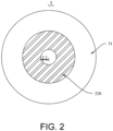
- the area of the first tab region 320 is S1
- the area of the end portion of the electrode assembly body 31 is S0
- the ratio of S1 to S0 is in the range of 0.3 to 0.5. It is worth noting that when the ratio of S1 to S0 is within 0.3 to 0.5, not only that it is possible to ensure overcurrent, but also it may be ensured that the area of the end surface of the electrode assembly 3 not covered by the tab region is large enough to facilitate infiltration of electrolyte.
- the orthographic projection area of the connecting piece 5 on the end surface of the electrode assembly body 31 is S2, and S2 ⁇ S1.
- the shape of the connecting piece 5 is circular, one end surface of the connecting piece 5 is welded and fixed to the end surface of the electrode pole 2, and the other end surface thereof is welded and fixed to the first tab 32.
- the welding process of the connecting piece 5 may be as follows: first, the connecting piece 5 is welded to the first tab 32 of the electrode assembly 3, then the electrode assembly 3 is loaded into the housing 1, a welding rod passes through the middle hole of the electrode assembly 3, and the connecting piece 5 and the electrode pole 2 are welded and fixed by using a torque welding process.
- FIG. 3 shows a schematic diagram of the second tab region 330 of the first type of cylindrical cell provided in the present disclosure.
- the orthographic projection of the second tab 33 at the second end of the electrode assembly body 31 is the second tab region 330, and a distance between any point on the inner boundary of the second tab region 330 and the centerline of the electrode assembly body 31 is L3; the radius of the inner side of the surrounding wall 12 is R0, and the ratio of L3 to R0 ranges from 0.5 to 0.8.
- the second tab structure of the electrode assembly 3 is cut, and the second tab 33 of the electrode assembly 3 is concentrated in the region of the electrode assembly body 31 away from the centerline of the electrode assembly body 31.
- the number of turns of the electrode assembly body 31 is N, with the innermost turn being the first turn and the outermost turn being the Nth turn, the second tab region 330 is located at 1/2 N turns to N turns of the electrode assembly body 31.
- the second tab region 330 may be set in the interval of n to 2n turns of the electrode assembly body 31.
- the second tab region 330 of the electrode assembly 3 is located between 1/2 N turns and N turns of the electrode assembly body 31, and the distance between any point on the outer boundary of the second tab region 330 and the outer side wall of the electrode assembly body 31 is 0.
- the second tab 33 is concentrated on one side close to the surrounding wall 12 of the housing 1, so that the second tab 33 can be directly welded to the surrounding wall 12 of the housing 1 to ensure the stability of the cylindrical cell.
- the first tab 32 is located at the first end of the electrode assembly body 31 facing the electrode pole 2, the first tab 32 is electrically connected to the electrode pole 2 through connecting piece 5, the second tab 33 is located at the second end of the electrode assembly body 31 facing away from the electrode pole 2, and the second tab 33 is electrically connected to the surrounding wall 12 of the housing 1.
- the distance L2 between any point on the inner boundary of the first tab region 320 of the electrode assembly 3 of the cylindrical cell in FIG. 1 and the centerline of the electrode assembly body 31 is equal to the radius of the middle hole in the electrode assembly 3.
- the distance L2 between any point on the inner boundary of the first tab region 320 and the centerline of the electrode assembly body 31 may also be set to be greater than the radius of the middle hole in the electrode assembly 3, so as to increase the path for infiltration of electrolyte.
Landscapes
- Chemical & Material Sciences (AREA)
- Chemical Kinetics & Catalysis (AREA)
- Electrochemistry (AREA)
- General Chemical & Material Sciences (AREA)
- Engineering & Computer Science (AREA)
- Manufacturing & Machinery (AREA)
- Connection Of Batteries Or Terminals (AREA)
- Sealing Battery Cases Or Jackets (AREA)
- Secondary Cells (AREA)
- Filling, Topping-Up Batteries (AREA)
- Battery Mounting, Suspending (AREA)
Abstract
Description
- The disclosure relates to the technical field of batteries, in particular to a cylindrical cell and an electronic device.
- Characterized in high energy density, high safety and low cost, cylindrical cell is now an important topic for research in the field of new energy power batteries. A cylindrical cell includes a housing, a electrode assembly, an electrode pole and a cover plate. The housing is a cylindrical structure with one end open. The electrode assembly is arranged in the housing, the electrode pole is fixed on the end wall of the housing and is electrically connected with the first tab of the electrode assembly, and the cover plate seals the open end of the housing and is electrically connected with the second tab of the electrode assembly.
- The electrode assembly of existing cylindrical cell includes a positive electrode sheet, a negative electrode sheet and a separator. One end of the positive electrode sheet is connected with a positive electrode tab, one end of the negative electrode sheet is connected with a negative electrode tab, and a certain number of positive electrode sheets, separators and negative electrode sheets are wound to form a electrode assembly after being stacked in a certain way. Then, the positive electrode tab assembly is shaped into a positive electrode tab by kneading, and the negative electrode tab assembly is shaped into a negative electrode tab by kneading. However, in the existing technology, since the tabs are not processed with cutting, and the kneading process is to shape the entire tab into a flat surface by using kneading rollers, the kneaded plane has high density. Since the entire end surface of the electrode assembly is covered by the kneaded tab, it is likely to cause difficulty in exhausting the cylindrical cell and poor electrolyte infiltration, which affect the reliability of the cylindrical cell.
- In light of the above, it is an urgent issue to provide a cylindrical cell to solve the above problems.
- A purpose of the present disclosure is to provide a cylindrical cell, the low density of the tab of the electrode assembly facilitates infiltration of the electrolyte and exhaust rate of the gas, improves the reliability of the cell.
- Another purpose of the present disclosure is to provide an electronic device, and the reliability and stability of the electronic device are good through use of the above-mentioned cylindrical cell.
- In order to achieve the above purpose, the following technical solutions are provided:
- In the first aspect, a cylindrical cell is provided, which includes: a housing, which includes an end wall and a surrounding wall enclosing the peripheral side of the end wall; an electrode pole, which penetrates through the end wall and is fixed to the end wall in an insulated manner; an electrode assembly, which is arranged in the housing, the electrode assembly includes an electrode assembly body and a first tab, the first tab is located at the first end of the electrode assembly body facing the electrode pole, the orthographic projection of the first tab on the first end of the electrode assembly body is the first tab region, and the distance between any point on the outer boundary of the first tab region and the inner side of the surrounding wall is L1, a radius of the inner side of the surrounding wall is R0, and the ratio of L1 to R0 ranges from 0.3 to 0.7.
- In an optional solution of the cylindrical cell, the area of the first tab region is S1, the area of the end portion of the electrode assembly body is S0, and the ratio of S1 to S0 is in the range of 0.3 to 0.5.
- In an optional solution for the cylindrical cell, the cylindrical cell further includes a connecting piece, and the connecting piece is arranged between the electrode pole and the first tab to electrically connect the electrode pole and the first tab.
- In an optional solution for the cylindrical cell, the orthographic projection area of the connecting piece on the first end of the electrode assembly body is S2, and S2≤S1.
- In an optional solution for the cylindrical cell, a liquid injection hole is provided on the electrode pole.
- In an optional solution for the cylindrical cell, the distance between any point on the inner boundary of the first tab region and the centerline of the electrode assembly body is L2, and the ratio of L2 to R0 ranges from 0.1 to 0.4.
- In an optional solution for the cylindrical cell, the number of turns of the electrode assembly body is N, with the innermost turn being the first turn, and the outermost turn being the Nth turn, the first tab region is located between 1/10 N turns and 2/5 N turns of the electrode assembly body.
- In an optional solution of the cylindrical cell, the cylindrical cell further includes a cover plate, and the cover plate is fixed to one end of the surrounding wall away from the end wall.
- In an optional solution for the cylindrical cell, the electrode assembly further includes a second tab, the second tab is arranged at the second end of the electrode assembly body close to the cover plate, and the second tab is directly and electrically connected to the cover plate, and the cover plate is electrically connected with the surrounding wall.
- In an optional solution for the cylindrical cell, the orthographic projection of the second tab on the electrode assembly body is a second tab region, and the distance between any point on the inner boundary of the second tab region and the centerline of the electrode assembly body is L3, and the ratio of L3 to R0 ranges from 0.5 to 0.8.
- In an optional solution for the cylindrical cell, the number of turns of the electrode assembly body is N, with the innermost turn being the first turn, and the outermost turn being the Nth turn, the second tab region is located between 1/2 N turns and N turns of the electrode assembly body.
- In a second aspect, an electronic device is provided, which includes the above-mentioned cylindrical cell.
- Compared with the related art, the advantageous effects of the present disclosure are as follows:
- The cylindrical cell provided by the present disclosure includes a housing, which includes an end wall and a surrounding wall enclosing the end wall; an electrode pole, which penetrates through the end wall and is connected to the end wall in an insulated manner; and a electrode assembly, which is arranged in the housing, and the electrode assembly includes a electrode assembly body and a first tab, the first tab is located at the first end of the electrode assembly body facing the electrode pole, the orthographic projection of the first tab on the first end of the electrode assembly body is the first tab region, and the distance between any point on the outer boundary of the first tab region and the inner side of the surrounding wall is L1, a radius of the inner side of the surrounding wall is R0, and the ratio of L1 to R0 ranges from 0.3 to 0.7. The first tab structure of the electrode assembly is cut to concentrate the first tab of the electrode assembly in the region of the electrode assembly body close to the centerline of the electrode assembly body. On the one hand, it is possible to reserve partial region of the end surface of the electrode assembly that is not covered by the kneaded tab, thereby improving the infiltration rate of the electrolyte and the exhaust rate of the gas generated inside the electrode assembly; on the other hand, by cutting unwanted tabs, the weight of the electrode assembly itself may be reduced, which helps to achieve lightweight design of cylindrical batteries.
- In the electronic device provided by the disclosure, the reliability and stability of the electronic device are good through use of the above-mentioned cylindrical cell.
- In order to more clearly illustrate the technical solutions in the embodiments of the present disclosure, the accompanying drawings that need to be used in the description of the embodiments of the present disclosure will be briefly described below. Clearly, the accompanying drawings in the following description are only some embodiments of the present disclosure. For those skilled in the art, other drawings can also be obtained according to the content of the embodiment and these drawings of the present disclosure without any inventive effort.
-
FIG. 1 is a cross-sectional diagram of the first type of cylindrical cell provided in an embodiment of the present disclosure. -
FIG. 2 is a schematic diagram of the first tab region of the first type of cylindrical cell provided in an embodiment of the present disclosure. -
FIG. 3 is a schematic diagram of the second tab region of the first type of cylindrical cell provided in an embodiment of the present disclosure. -
FIG. 4 is a cross-sectional diagram of the second type of cylindrical cell provided in an embodiment of the present disclosure. -
FIG. 5 is a schematic structural diagram of the electrode pole end of the second type of cylindrical cell provided in an embodiment of the present disclosure. -
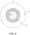
FIG. 6 is a schematic diagram of the first tab region of the second type of cylindrical cell provided in an embodiment of the present disclosure. -
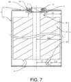
FIG. 7 is a cross-sectional diagram of the third type of cylindrical cell provided in an embodiment of the present disclosure. -
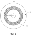
FIG. 8 is a schematic diagram of the second tab region of the third type of cylindrical cell provided in an embodiment of the present disclosure. - In order to better describe the technical problem to be solved by the disclosure, the adopted technical solution and the achieved technical effect, the technical solution of the disclosure will be further described below in conjunction with the accompanying drawings and through specific implementation methods.
- In the description of the present disclosure, unless otherwise clearly specified and limited, the terms "connected", "linked" and "fixed" should be understood in a broad sense, for example, the above terms may refer to a fixed connection, a detachable connection, or integral formation; mechanical or electrical connection; direction connection or indirect connection through an intermediary; or the internal communication of two components or the interaction relationship between two components. Those of ordinary skill in the art can understand the specific meanings of the above terms in the present disclosure in specific situations.
- In the present disclosure, unless otherwise clearly specified and limited, a first feature being "on" or "below" a second feature may indicate direct contact between the first and second features, and may also indicate that the first and second features are not in direct contact but are in indirect contact through another feature between them. Moreover, the first feature being "above", "over" and "on" the second feature indicates that the first feature is directly above and obliquely above the second feature, or merely indicates that the first feature is at a level higher than the second feature. The first feature being "below", "beneath" and "under" the second feature indicates that the first feature is directly below and obliquely below the second feature, or simply means that the first feature is at a level lower than the second feature.
- In the description of the present disclosure, the orientation or positional relationship of the terms "upper", "lower", "left", "right" is interpreted based on the orientation or positional relationship shown in the accompanying drawings, and are only for the convenience of description and simplification of operation. It does not indicate or imply that the device or element referred to must have a specific orientation, be constructed and operate in a specific orientation, and therefore should not be construed as limitation to the present disclosure. In addition, the terms "first" and "second" are only used for discrimination in description, and have no special meaning.
-
FIG. 1 shows a cross-sectional view of the first type of cylindrical cell provided in the present disclosure. As shown inFIG. 1 , the cylindrical cell includes a housing 1, anelectrode pole 2, anelectrode assembly 3, acover plate 4, a connectingpiece 5, a firstinsulating member 61, a secondinsulating member 62, afirst sealing member 71 and asecond sealing member 72. The housing 1 includes anend wall 11 and a surroundingwall 12 enclosing the peripheral side of theend wall 11; theelectrode pole 2 passes through theend wall 11 and is fixed to theend wall 11 in an insulated manner; theelectrode assembly 3 is arranged in the housing 1, and theelectrode assembly 3 is electrically connected to theelectrode pole 2 through the connectingpiece 5; and thecover plate 4 is fixed on one end of the surroundingwall 12 away from theend wall 11. Theelectrode pole 2 is riveted and fixed to theend wall 11. Afirst sealing member 71 and a first insulatingmember 61 are provided between the upper end of theelectrode pole 2 and the outer surface of theend wall 11. Thefirst sealing member 71 encloses the peripheral side of theelectrode pole 2, the firstinsulating member 61 encloses the peripheral side of thefirst sealing member 71, and a secondinsulating member 62 is provided between the lower end of theelectrode pole 2 and the inner surface of theend wall 11 to ensure the insulated connection between theelectrode pole 2 as well as the connectingpiece 5 and the housing 1. The packaging process of the housing 1 and thecover plate 4 may be as follows: one end of the surroundingwall 12 of the housing 1 away from theend wall 11 is subjected to a roll-grooving treatment, then thesecond sealing member 72 covers the peripheral side of thecover plate 4, the assembly body of thecover plate 4 and thesecond sealing member 72 is placed in the roller groove, and finally the surroundingwall 12 of the housing 1 is bent inward and fixed on thecover plate 4 to complete the packaging of the housing 1. - Further referring to
FIG. 1 , theelectrode assembly 3 includes anelectrode assembly body 31, afirst tab 32 and asecond tab 33. Thefirst tab 32 is arranged at the first end of theelectrode assembly body 31 facing theelectrode pole 2, and thefirst tab 32 is electrically connected to theelectrode pole 2 through the connectingpiece 5. Thesecond tab 33 is disposed at the second end of theelectrode assembly body 31 facing away from theelectrode pole 2, and thesecond tab 33 is electrically connected to the surroundingwall 12 of the housing 1. Exemplarily, thefirst tab 32 is a positive electrode tab, and thesecond tab 33 is a negative electrode tab. It should be noted that the processing technology of theelectrode assembly 3 is as follows: theelectrode assembly 3 is formed by winding the first electrode, the second electrode and the separator between the first electrode and the second electrode around the winding axis. The first electrode and the second electrode respectively include a first uncoated region and a second uncoated region that are not coated with an active material layer along the winding direction, and the first uncoated region and the second uncoated region are respectively located on the two end surfaces of the electrode assembly. Thefirst tab 32 is formed by the first uncoated region, and thesecond tab 33 is formed by the second uncoated region. -
FIG. 2 shows a schematic diagram of thefirst tab region 320 of the first type of cylindrical cell provided in the present disclosure. As shown inFIG. 2 in conjunction withFIG. 1 , the orthographic projection of thefirst tab 32 at the first end of theelectrode assembly body 31 is thefirst tab region 320, and a distance between any point on the outer boundary of thefirst tab region 320 and the inner side of the surroundingwall 12 is L1; the radius of the inner side of the surroundingwall 12 is R0, and the ratio of L1 to R0 ranges from 0.3 to 0.7. It is worth noting that when the ratio of L1 to R0 is greater than 0.7, the area occupied by thefirst tab region 320 is too small, and which causes the following defects. First, the overcurrent capability of the cell is reduced, making it impossible to realize high-power discharging. Secondly, if the tab region is too small, the resistance of the corresponding tab will be large, and there will be a lot of heat generated at the tab during the cell discharge process, which is likely to cause cell thermal runaway. When the ratio of L1 to R0 is less than 0.3, thefirst tab region 320 almost covers the position close to the housing 1, which hinders infiltration of the electrolyte. The first tab structure of theelectrode assembly 3 is cut, and thefirst tab 32 of theelectrode assembly 3 is concentrated in the region of theelectrode assembly body 31 close to the centerline of theelectrode assembly body 31. On the one hand, it is possible to reduce the density of thefirst tab 32 and improve the infiltration rate and exhaust rate of theelectrode assembly 3; on the other hand, it is possible to reduce the weight of theelectrode assembly 3 itself to facilitate lightweight design of the cylindrical cell. It should be noted that in the related art, it is generally necessary to knead/bend the tab before connecting the tab to the connectingpiece 5. The tab region mentioned in this disclosure is the region where the orthographic projection is formed on theelectrode assembly body 31 after the tab is kneaded/bent. For example, thefirst tab region 320 is the orthographic projection region formed on the end surface of theelectrode assembly body 31 after thefirst tab 32 is kneaded/bent, and thesecond tab region 330 is the orthographic projection region formed on the end surface of theelectrode assembly body 31 after thesecond tab 33 is kneaded/bent. - Further referring to
FIG. 2 , the area of thefirst tab region 320 is S1, the area of the end portion of theelectrode assembly body 31 is S0, and the ratio of S1 to S0 is in the range of 0.3 to 0.5. It is worth noting that when the ratio of S1 to S0 is within 0.3 to 0.5, not only that it is possible to ensure overcurrent, but also it may be ensured that the area of the end surface of theelectrode assembly 3 not covered by the tab region is large enough to facilitate infiltration of electrolyte. In order to further reduce the weight of the cylindrical cell, the orthographic projection area of the connectingpiece 5 on the end surface of theelectrode assembly body 31 is S2, and S2≤S1. Such arrangement not only makes it possible to realize the welding and fixing of thefirst tab 32 and the connectingpiece 5, but also reduce the size of the connectingpiece 5 and decrease the weight of the connectingpiece 5. Exemplarily, the shape of the connectingpiece 5 is circular, one end surface of the connectingpiece 5 is welded and fixed to the end surface of theelectrode pole 2, and the other end surface thereof is welded and fixed to thefirst tab 32. The welding process of the connectingpiece 5 may be as follows: first, the connectingpiece 5 is welded to thefirst tab 32 of theelectrode assembly 3, then theelectrode assembly 3 is loaded into the housing 1, a welding rod passes through the middle hole of theelectrode assembly 3, and the connectingpiece 5 and theelectrode pole 2 are welded and fixed by using a torque welding process. -
FIG. 3 shows a schematic diagram of thesecond tab region 330 of the first type of cylindrical cell provided in the present disclosure. As shown inFIG. 3 in conjunction withFIG. 1 , the orthographic projection of thesecond tab 33 at the second end of theelectrode assembly body 31 is thesecond tab region 330, and a distance between any point on the inner boundary of thesecond tab region 330 and the centerline of theelectrode assembly body 31 is L3; the radius of the inner side of the surroundingwall 12 is R0, and the ratio of L3 to R0 ranges from 0.5 to 0.8. The second tab structure of theelectrode assembly 3 is cut, and thesecond tab 33 of theelectrode assembly 3 is concentrated in the region of theelectrode assembly body 31 away from the centerline of theelectrode assembly body 31. On the one hand, it is possible to reduce the density of thesecond tab 33 and improve the infiltration rate and exhaust rate of theelectrode assembly 3; on the other hand, it is possible to reduce the weight of theelectrode assembly 3 itself to facilitate lightweight design of the cylindrical cell. - The number of turns of the
electrode assembly body 31 is N, with the innermost turn being the first turn and the outermost turn being the Nth turn, thesecond tab region 330 is located at 1/2 N turns to N turns of theelectrode assembly body 31. Exemplarily, when N=2n, n is a positive integer, thesecond tab region 330 may be set in the interval of n to 2n turns of theelectrode assembly body 31. When N ≠ 2n, n is a positive integer, 1/2 N is rounded off to obtain a positive integer, and thesecond tab region 330 falls within 1/2 N turns and N turns of theelectrode assembly body 31. InFIG. 3 , thesecond tab region 330 of theelectrode assembly 3 is located between 1/2 N turns and N turns of theelectrode assembly body 31, and the distance between any point on the outer boundary of thesecond tab region 330 and the outer side wall of theelectrode assembly body 31 is 0. Thesecond tab 33 is concentrated on one side close to the surroundingwall 12 of the housing 1, so that thesecond tab 33 can be directly welded to the surroundingwall 12 of the housing 1 to ensure the stability of the cylindrical cell. - In the cylindrical cell, on the one hand, both ends of the
electrode assembly body 31 have areas not covered by the tab, so that it is possible to increase the infiltration rate and exhaust rate of theelectrode assembly 3. On the other hand, half-tab and no-tab designs help to reduce the weight of the electrode assembly to optimize the structure of the cylindrical cell and improve the density of energy. -
FIG. 4 shows a schematic cross-sectional view of the second type of cylindrical cell provided in the disclosure. As shown inFIG. 4 , the cylindrical cell includes a housing 1, anelectrode pole 2, anelectrode assembly 3, acover plate 4, connectingpiece 5, a first insulatingmember 61, a second insulatingmember 62, a first sealingmember 71 and asecond sealing member 72. The housing 1 includes anend wall 11 and a surroundingwall 12 enclosing theend wall 11; theelectrode pole 2 passes through theend wall 11 and is connected to theend wall 11 in an insulated manner; theelectrode assembly 3 is arranged in the housing 1, and theelectrode assembly 3 is electrically connected to theelectrode pole 2 through the connectingpiece 5; and thecover plate 4 is fixed on one end of the surroundingwall 12 away from theend wall 11. Theelectrode pole 2 is riveted and fixed to theend wall 11. A first sealingmember 71 and a first insulatingmember 61 are provided between the upper end of theelectrode pole 2 and the outer surface of theend wall 11. Thefirst sealing member 71 encloses the peripheral side of theelectrode pole 2, the first insulatingmember 61 encloses the peripheral side of the first sealingmember 71, and a second insulatingmember 62 is provided between the lower end of theelectrode pole 2 and the inner surface of theend wall 11 to ensure the insulated connection between theelectrode pole 2 and the housing 1. The packaging process of the housing 1 and thecover plate 4 may be as follows: one end of the surroundingwall 12 of the housing 1 away from theend wall 11 is subjected to a roll-grooving treatment, then the second sealingmember 72 covers the peripheral side of thecover plate 4, the assembly body of thecover plate 4 and the second sealingmember 72 is placed in the roller groove, and finally the surroundingwall 12 of the housing 1 is bent inward and fixed on thecover plate 4 to complete the packaging of the housing 1. Theelectrode assembly 3 includes anelectrode assembly body 31, afirst tab 32 and asecond tab 33. Thefirst tab 32 is located at the first end of theelectrode assembly body 31 facing theelectrode pole 2, thefirst tab 32 is electrically connected to theelectrode pole 2 through connectingpiece 5, thesecond tab 33 is located at the second end of theelectrode assembly body 31 facing away from theelectrode pole 2, and thesecond tab 33 is electrically connected to the surroundingwall 12 of the housing 1. - The packaging process of the second type of cylindrical cell in
FIG. 4 is the same as that of thecover plate 4 of the first type of cylindrical cell inFIG. 1 , and details will not be repeated here. The main difference between the two is that inFIG. 4 , theelectrode pole 2 is provided with aliquid injection hole 21 through which the electrolyte is injected into the housing 1. The liquid injection process of the second type of cylindrical cell may be as follows: first, theelectrode pole 2 is riveted on theend wall 11 of the housing 1, and then assembly body of theelectrode assembly 3 and the connectingpiece 5 are loaded, and after thecover plate 4 is packaged, the electrolyte is injected into theliquid injection hole 21 of theelectrode pole 2, and finally theliquid injection hole 21 is sealed by a sealing nail. -
FIG. 5 shows a partial schematic diagram of theelectrode pole 2 end of the cylindrical cell inFIG. 4 .FIG. 6 shows a schematic diagram of thefirst tab region 320 of the cylindrical cell inFIG. 4 . As shown inFIG. 5 to FIG. 6 , the distance between any point on the inner boundary of thefirst tab region 320 and the centerline of theelectrode assembly body 31 is L2, and the ratio of L2 to R0 ranges from 0.1 to 0.4. Such setting makes thefirst tab 32 of theelectrode assembly 3 deviate from theliquid injection hole 21, so that the electrolyte is able to quickly flow into theelectrode assembly 3 and increase the infiltration rate of theelectrode assembly 3. The liquid injection method of the cylindrical cell inFIG. 1 is performed by injecting liquid on thecover plate 4 side of the housing 1, and thecover plate 4 is packaged after liquid injection. Therefore, the distance L2 between any point on the inner boundary of thefirst tab region 320 of theelectrode assembly 3 of the cylindrical cell inFIG. 1 and the centerline of theelectrode assembly body 31 is equal to the radius of the middle hole in theelectrode assembly 3. Of course, in the embodiment ofFIG. 1 , the distance L2 between any point on the inner boundary of thefirst tab region 320 and the centerline of theelectrode assembly body 31 may also be set to be greater than the radius of the middle hole in theelectrode assembly 3, so as to increase the path for infiltration of electrolyte. - Further, the connecting
piece 5 is provided with a throughhole 51 corresponding to theliquid injection hole 21, so that the electrolyte is able to flow into theelectrode assembly 3 through the throughhole 51. In addition, in order to facilitate the welding and fixing of the connectingpiece 5 and theelectrode pole 2, the diameter of the throughhole 51 of the connectingpiece 5 is smaller than the diameter of the middle hole of theelectrode assembly 3, and the diameter of the end surface of theelectrode pole 2 facing the connectingpiece 5 is greater than the diameter of the throughhole 51 of the connectingpiece 5. - Further referring to
FIG. 6 , the number of turns of theelectrode assembly body 31 is N, with the innermost turn being the first turn and the outermost turn being the Nth turn, thefirst tab region 320 is located between 1/10 N turns and 2/5 N turns of theelectrode assembly body 31. Preferably, thefirst tab region 320 is located between 1/3 N turns to 2/3 N turns of theelectrode assembly body 31. Exemplarily, when N=3n, n is a positive integer, thefirst tab region 320 may be set in the interval of n to 2n turns of theelectrode assembly body 31. When N ≠ 3n, n is a positive integer, 1/3 N and 2/3 N are rounded to obtain positive integers, and thefirst tab region 320 is located between 1/3 N turns and 2/3 N turns of theelectrode assembly body 31. -
FIG. 7 shows a schematic cross-sectional view of the third type of cylindrical cell provided in the present disclosure. As shown inFIG. 7 , the third type of cylindrical cell includes a housing 1, anelectrode pole 2, anelectrode assembly 3, acover plate 4, a connectingpiece 5, a first insulatingmember 61, a first sealingmember 71 and asecond sealing member 72. The housing 1 includes anend wall 11 and a surroundingwall 12 enclosing theend wall 11; theelectrode pole 2 passes through theend wall 11 and is connected to theend wall 11 in an insulated manner; theelectrode assembly 3 is arranged in the housing 1, and theelectrode assembly 3 is electrically connected to theelectrode pole 2 through the connectingpiece 5; and thecover plate 4 is fixed on one end of the surroundingwall 12 away from theend wall 11. Theelectrode pole 2 is riveted and fixed to theend wall 11. A first sealingmember 71 and a first insulatingmember 61 are provided between the upper end of theelectrode pole 2 and the outer surface of theend wall 11. Thefirst sealing member 71 encloses the peripheral side of theelectrode pole 2, the first insulatingmember 61 encloses the peripheral side of the first sealingmember 71, and a second insulatingmember 62 is provided between the lower end of theelectrode pole 2 and the inner surface of theend wall 11 to ensure the insulated connection between theelectrode pole 2 as well as the connectingpiece 5 and the housing 1. The packaging process of the housing 1 and thecover plate 4 may be as follows: thecover plate 4 is welded and fixed to the surroundingwall 12 of the housing 1. Theelectrode assembly 3 includes anelectrode assembly body 31, afirst tab 32 and asecond tab 33. Thefirst tab 32 is located at the first end of theelectrode assembly body 31 facing theelectrode pole 2, thefirst tab 32 is electrically connected to theelectrode pole 2 through a connectingpiece 5, thesecond tab 33 is located at the second end of theelectrode assembly body 31 facing away from theelectrode pole 2, and thesecond tab 33 is electrically connected to thecover plate 4. - The liquid injection process of the third type of cylindrical cell in
FIG. 7 is the same as that of the second type of cylindrical cell inFIG. 4 , and the liquid injection is realized by providing aliquid injection hole 21 on theelectrode pole 2, the details will not be repeated here. The main difference between the two is that inFIG. 7 , thecover plate 4 is directly and electrically connected to thesecond tab 33 of theelectrode assembly 3, and then thecover plate 4 is welded and fixed to the surroundingwall 12 of the housing 1. -
FIG. 8 shows a schematic diagram of thesecond tab region 330 of the cylindrical cell inFIG. 7 . As shown inFIG. 8 combined withFIG. 7 , the orthographic projection of thesecond tab 33 at the second end of theelectrode assembly body 31 is thesecond tab region 330, and a distance between any point on the inner boundary of thesecond tab region 330 and the centerline of theelectrode assembly body 31 is L3; the radius of the inner side of the surroundingwall 12 is R0, and the ratio of L3 to R0 ranges from 0.5 to 0.8. The distance between the outer boundary of thesecond tab region 330 and the inner side of the surroundingwall 12 is L4, and the ratio of L4 to R0 ranges from 0.2 to 0.4. In this way, thesecond tab 33 of theelectrode assembly 3 may be concentrated at a position toward the outside from the center of theelectrode assembly body 31, so as to facilitate the welding and fixing of thesecond tab 33 and thecover plate 4. - Of course, the form of electrical connection between the
second tab 33 of theelectrode assembly 3 and the housing 1 is not limited to the above examples. In other embodiments, it might be that the cylindrical cell further includes a negative electrode connecting piece, thenegative electrode tab 33 is electrically connected to the negative electrode connecting piece, and the negative electrode connecting piece is electrically connected to the housing 1. - The present disclosure further provides an electronic device, which includes the cylindrical cell. By using the cylindrical cell, the electronic device has high energy density and stable performance, and may improve user experience.
- Optionally, the electronic device may be a power cell of a new energy vehicle, a new energy storage device, an electronic product, etc., which will not be described here in details.
- Note that in the description of this present disclosure, some expressions such as "some embodiments", "other embodiments" and the like mean that the specific features, structures, materials or characteristics described in conjunction with the embodiments or examples are included in at least one embodiment or example of the disclosure. In this present disclosure, schematic expression of the above terms do not necessarily refer to the same embodiment or example. Furthermore, the particular features, structures, materials or characteristics described may be combined in any suitable manner in any one or more embodiments or examples.
Claims (11)
- A cylindrical cell, comprising:a housing (1), having an end wall (11) and a surrounding wall (12) enclosing a peripheral side of the end wall (11);an electrode pole (2), penetrating through the end wall (11) and being fixed to the end wall (11) in an insulated manner;an electrode assembly (3), disposed in the housing (1), wherein the electrode assembly (3) comprises a electrode assembly body (31) and a first tab (32), the first tab (32) is located at a first end of the electrode assembly body (31) facing the electrode pole (2), an orthographic projection of the first tab (32) on the first end of the electrode assembly body (31) is a first tab region (320), and a distance between any point on an outer boundary of the first tab region (320) and an inner side of the surrounding wall (12) is L1, a radius of the inner side of the surrounding wall (12) is R0, and a ratio of L1 to R0 ranges from 0.3 to 0.7.
- The cylindrical cell according to claim 1, wherein an area of the first tab region (320) is S1, an area of an end portion of the electrode assembly body (31) is S0, and a ratio of S1 to S0 is in a range of 0.3 to 0.5.
- The cylindrical cell according to claim 1 or 2, wherein the cylindrical cell further comprises a connecting piece (5), and the connecting piece (5) is disposed between the electrode pole (2) and the first tab (32) to electrically connect the electrode pole (2) and the first tab (32).
- The cylindrical cell according to any one of claims 1 to 3, wherein an orthographic projection area of the connecting piece (5) on the first end of the electrode assembly body (31) is S2, and S2≤S1.
- The cylindrical cell according to any one of claims 1 to 4, wherein the electrode pole (2) comprises a liquid injection hole (21).
- The cylindrical cell according to any one of claims 1 to 5, wherein a distance between any point on an inner boundary of the first tab region (320) and a centerline of the surrounding wall (12) is L2, and a ratio of L2 to R0 ranges from 0.1 to 0.4.
- The cylindrical cell according to any one of claims 1 to 6, wherein the number of turns of the electrode assembly body (31) is N, with an innermost turn being a first turn, and an outermost turn being a Nth turn, the first tab region (320) is located between 1/10 N turns and 2/5 N turns of the electrode assembly body (31).
- The cylindrical cell according to any one of claims 1 to 7, wherein the cylindrical cell further comprises a cover plate (4), and the cover plate (4) is fixed to one end of the surrounding wall (12) away from the end wall (11).
- The cylindrical cell according to any one of claims 1 to 8, wherein the electrode assembly (3) further comprises a second tab (33), the second tab (33) is disposed at a second end of the electrode assembly body (31) close to the cover plate (4), and the second tab (33) is directly and electrically connected to the cover plate (4), and the cover plate (4) is electrically connected with the surrounding wall (12).
- The cylindrical cell according to any one of claims 1 to 9, wherein an orthographic projection of the second tab (33) on the electrode assembly body (31) is a second tab region (330), and a distance between any point on an inner boundary of the second tab region (330) and a centerline of the electrode assembly body (31) is L3, and a ratio of L3 to R0 ranges from 0.5 to 0.8;
the number of turns of the electrode assembly body (31) is N, with the innermost turn being the first turn, and the outermost turn being the Nth turn, the second tab region (330) is located between 1/2 N turns and N turns of the electrode assembly body (31). - An electronic device, comprising the cylindrical cell according to any one of claims 1 to 10.
Applications Claiming Priority (1)
| Application Number | Priority Date | Filing Date | Title |
|---|---|---|---|
| CN202223570242.3U CN219203434U (en) | 2022-12-29 | 2022-12-29 | A cylindrical battery and electronic equipment |
Publications (2)
| Publication Number | Publication Date |
|---|---|
| EP4394963A1 true EP4394963A1 (en) | 2024-07-03 |
| EP4394963B1 EP4394963B1 (en) | 2025-10-08 |
Family
ID=86378378
Family Applications (1)
| Application Number | Title | Priority Date | Filing Date |
|---|---|---|---|
| EP23173023.5A Active EP4394963B1 (en) | 2022-12-29 | 2023-05-12 | Cylindrical cell and electronic device |
Country Status (5)
| Country | Link |
|---|---|
| US (1) | US20240222804A1 (en) |
| EP (1) | EP4394963B1 (en) |
| JP (1) | JP7634048B2 (en) |
| CN (1) | CN219203434U (en) |
| ES (1) | ES3049359T3 (en) |
Families Citing this family (2)
| Publication number | Priority date | Publication date | Assignee | Title |
|---|---|---|---|---|
| CN119725912A (en) * | 2023-09-26 | 2025-03-28 | 宁德时代新能源科技股份有限公司 | Battery cells, batteries and electrical devices |
| CN117691204B (en) * | 2023-12-11 | 2025-04-04 | 无锡市金杨新材料股份有限公司 | A battery with dense tabs |
Citations (4)
| Publication number | Priority date | Publication date | Assignee | Title |
|---|---|---|---|---|
| US20050260487A1 (en) * | 2004-05-19 | 2005-11-24 | Hyon-Sok Kim | Collecting plate and secondary battery with the same |
| US20060281252A1 (en) * | 2005-06-08 | 2006-12-14 | Marc Oversteyns | Metal interconnect for capacitor |
| US20140308554A1 (en) * | 2013-04-10 | 2014-10-16 | Maxwell Technologies, Inc. | Collector plate for energy storage device and methods of manufacturing |
| CN114284570A (en) * | 2021-12-28 | 2022-04-05 | 宁德新能源科技有限公司 | Battery cell, battery and electric equipment |
Family Cites Families (5)
| Publication number | Priority date | Publication date | Assignee | Title |
|---|---|---|---|---|
| US4963446A (en) * | 1989-04-05 | 1990-10-16 | Eveready Battery Co., Inc. | Inwardly indented edge electrode assembly |
| JP6201449B2 (en) | 2013-06-25 | 2017-09-27 | 株式会社Gsユアサ | battery |
| JP7488008B2 (en) | 2020-03-23 | 2024-05-21 | Fdk株式会社 | Alkaline storage battery |
| KR102919244B1 (en) | 2020-06-03 | 2026-01-27 | 주하이 코스엠엑스 배터리 컴퍼니 리미티드 | Button type battery and manufacturing method thereof, electronic device |
| KR20230047951A (en) | 2021-09-29 | 2023-04-10 | 컨템포러리 엠퍼렉스 테크놀로지 씨오., 리미티드 | Electrode assembly, its manufacturing method and equipment, battery and electric device |
-
2022
- 2022-12-29 CN CN202223570242.3U patent/CN219203434U/en active Active
-
2023
- 2023-04-20 US US18/303,583 patent/US20240222804A1/en active Pending
- 2023-05-12 EP EP23173023.5A patent/EP4394963B1/en active Active
- 2023-05-12 ES ES23173023T patent/ES3049359T3/en active Active
- 2023-08-12 JP JP2023131732A patent/JP7634048B2/en active Active
Patent Citations (4)
| Publication number | Priority date | Publication date | Assignee | Title |
|---|---|---|---|---|
| US20050260487A1 (en) * | 2004-05-19 | 2005-11-24 | Hyon-Sok Kim | Collecting plate and secondary battery with the same |
| US20060281252A1 (en) * | 2005-06-08 | 2006-12-14 | Marc Oversteyns | Metal interconnect for capacitor |
| US20140308554A1 (en) * | 2013-04-10 | 2014-10-16 | Maxwell Technologies, Inc. | Collector plate for energy storage device and methods of manufacturing |
| CN114284570A (en) * | 2021-12-28 | 2022-04-05 | 宁德新能源科技有限公司 | Battery cell, battery and electric equipment |
Also Published As
| Publication number | Publication date |
|---|---|
| JP7634048B2 (en) | 2025-02-20 |
| EP4394963B1 (en) | 2025-10-08 |
| CN219203434U (en) | 2023-06-16 |
| US20240222804A1 (en) | 2024-07-04 |
| JP2024095950A (en) | 2024-07-11 |
| ES3049359T3 (en) | 2025-12-16 |
Similar Documents
| Publication | Publication Date | Title |
|---|---|---|
| JP7367742B2 (en) | Energy storage element | |
| CN220122063U (en) | Battery cells, batteries and electrical devices | |
| CN107710459B (en) | Batteries and battery packs | |
| US20220181725A1 (en) | Secondary battery | |
| JP5538114B2 (en) | Secondary battery | |
| EP4394963B1 (en) | Cylindrical cell and electronic device | |
| CN100479232C (en) | Electrode assembly and lithium ion secondary battery using the same | |
| JP2007265846A (en) | Cylindrical battery and its manufacturing method | |
| WO2013099295A1 (en) | Cylindrical lithium-ion cell | |
| JP2011054555A (en) | Electrode assembly, and rechargeable battery with the same | |
| US20220200110A1 (en) | Secondary battery | |
| WO2023050124A1 (en) | Electrode assembly and manufacturing method and device therefor, battery and electrical apparatus | |
| EP4318768A1 (en) | Sealed battery | |
| JP2008171678A (en) | Nonaqueous electrolyte secondary battery | |
| JP2006079942A (en) | Battery | |
| JP2011054378A (en) | Nonaqueous electrolyte secondary battery | |
| JP2011070977A (en) | Laminated battery | |
| EP4300644A1 (en) | Cylindrical battery | |
| JP3433695B2 (en) | Cylindrical lithium-ion battery | |
| WO2025082047A1 (en) | Electrode sheet, electrode assembly, battery cell, battery, and electric device | |
| CN218996816U (en) | Coiled cell and battery cell | |
| US20220216545A1 (en) | Flat secondary battery | |
| WO2023145736A1 (en) | Power storage device | |
| EP4723263A1 (en) | Power storage device | |
| JP2006338979A (en) | Cylindrical lithium secondary battery |
Legal Events
| Date | Code | Title | Description |
|---|---|---|---|
| PUAI | Public reference made under article 153(3) epc to a published international application that has entered the european phase |
Free format text: ORIGINAL CODE: 0009012 |
|
| STAA | Information on the status of an ep patent application or granted ep patent |
Free format text: STATUS: REQUEST FOR EXAMINATION WAS MADE |
|
| 17P | Request for examination filed |
Effective date: 20230512 |
|
| AK | Designated contracting states |
Kind code of ref document: A1 Designated state(s): AL AT BE BG CH CY CZ DE DK EE ES FI FR GB GR HR HU IE IS IT LI LT LU LV MC ME MK MT NL NO PL PT RO RS SE SI SK SM TR |
|
| GRAP | Despatch of communication of intention to grant a patent |
Free format text: ORIGINAL CODE: EPIDOSNIGR1 |
|
| STAA | Information on the status of an ep patent application or granted ep patent |
Free format text: STATUS: GRANT OF PATENT IS INTENDED |
|
| INTG | Intention to grant announced |
Effective date: 20250604 |
|
| GRAS | Grant fee paid |
Free format text: ORIGINAL CODE: EPIDOSNIGR3 |
|
| GRAA | (expected) grant |
Free format text: ORIGINAL CODE: 0009210 |
|
| STAA | Information on the status of an ep patent application or granted ep patent |
Free format text: STATUS: THE PATENT HAS BEEN GRANTED |
|
| AK | Designated contracting states |
Kind code of ref document: B1 Designated state(s): AL AT BE BG CH CY CZ DE DK EE ES FI FR GB GR HR HU IE IS IT LI LT LU LV MC ME MK MT NL NO PL PT RO RS SE SI SK SM TR |
|
| REG | Reference to a national code |
Ref country code: GB Ref legal event code: FG4D Ref country code: CH Ref legal event code: F10 Free format text: ST27 STATUS EVENT CODE: U-0-0-F10-F00 (AS PROVIDED BY THE NATIONAL OFFICE) Effective date: 20251008 |
|
| REG | Reference to a national code |
Ref country code: DE Ref legal event code: R096 Ref document number: 602023007246 Country of ref document: DE |
|
| REG | Reference to a national code |
Ref country code: IE Ref legal event code: FG4D |
|
| REG | Reference to a national code |
Ref country code: ES Ref legal event code: FG2A Ref document number: 3049359 Country of ref document: ES Kind code of ref document: T3 Effective date: 20251216 |
|
| REG | Reference to a national code |
Ref country code: NL Ref legal event code: MP Effective date: 20251008 |
|
| REG | Reference to a national code |
Ref country code: AT Ref legal event code: MK05 Ref document number: 1845613 Country of ref document: AT Kind code of ref document: T Effective date: 20251008 |
|
| PG25 | Lapsed in a contracting state [announced via postgrant information from national office to epo] |
Ref country code: NL Free format text: LAPSE BECAUSE OF FAILURE TO SUBMIT A TRANSLATION OF THE DESCRIPTION OR TO PAY THE FEE WITHIN THE PRESCRIBED TIME-LIMIT Effective date: 20251008 |
|
| REG | Reference to a national code |
Ref country code: LT Ref legal event code: MG9D |
|
| PG25 | Lapsed in a contracting state [announced via postgrant information from national office to epo] |
Ref country code: NO Free format text: LAPSE BECAUSE OF FAILURE TO SUBMIT A TRANSLATION OF THE DESCRIPTION OR TO PAY THE FEE WITHIN THE PRESCRIBED TIME-LIMIT Effective date: 20260108 |
|
| PG25 | Lapsed in a contracting state [announced via postgrant information from national office to epo] |
Ref country code: HR Free format text: LAPSE BECAUSE OF FAILURE TO SUBMIT A TRANSLATION OF THE DESCRIPTION OR TO PAY THE FEE WITHIN THE PRESCRIBED TIME-LIMIT Effective date: 20251008 Ref country code: FI Free format text: LAPSE BECAUSE OF FAILURE TO SUBMIT A TRANSLATION OF THE DESCRIPTION OR TO PAY THE FEE WITHIN THE PRESCRIBED TIME-LIMIT Effective date: 20251008 Ref country code: AT Free format text: LAPSE BECAUSE OF FAILURE TO SUBMIT A TRANSLATION OF THE DESCRIPTION OR TO PAY THE FEE WITHIN THE PRESCRIBED TIME-LIMIT Effective date: 20251008 |
|
| PG25 | Lapsed in a contracting state [announced via postgrant information from national office to epo] |
Ref country code: RS Free format text: LAPSE BECAUSE OF FAILURE TO SUBMIT A TRANSLATION OF THE DESCRIPTION OR TO PAY THE FEE WITHIN THE PRESCRIBED TIME-LIMIT Effective date: 20260108 |
|
| PG25 | Lapsed in a contracting state [announced via postgrant information from national office to epo] |
Ref country code: IS Free format text: LAPSE BECAUSE OF FAILURE TO SUBMIT A TRANSLATION OF THE DESCRIPTION OR TO PAY THE FEE WITHIN THE PRESCRIBED TIME-LIMIT Effective date: 20260208 |
|
| PGFP | Annual fee paid to national office [announced via postgrant information from national office to epo] |
Ref country code: FR Payment date: 20260323 Year of fee payment: 4 |
|
| PG25 | Lapsed in a contracting state [announced via postgrant information from national office to epo] |
Ref country code: PT Free format text: LAPSE BECAUSE OF FAILURE TO SUBMIT A TRANSLATION OF THE DESCRIPTION OR TO PAY THE FEE WITHIN THE PRESCRIBED TIME-LIMIT Effective date: 20260209 |
|
| PG25 | Lapsed in a contracting state [announced via postgrant information from national office to epo] |
Ref country code: PL Free format text: LAPSE BECAUSE OF FAILURE TO SUBMIT A TRANSLATION OF THE DESCRIPTION OR TO PAY THE FEE WITHIN THE PRESCRIBED TIME-LIMIT Effective date: 20251008 |
|
| PG25 | Lapsed in a contracting state [announced via postgrant information from national office to epo] |
Ref country code: LV Free format text: LAPSE BECAUSE OF FAILURE TO SUBMIT A TRANSLATION OF THE DESCRIPTION OR TO PAY THE FEE WITHIN THE PRESCRIBED TIME-LIMIT Effective date: 20251008 |
|
| PG25 | Lapsed in a contracting state [announced via postgrant information from national office to epo] |
Ref country code: BG Free format text: LAPSE BECAUSE OF FAILURE TO SUBMIT A TRANSLATION OF THE DESCRIPTION OR TO PAY THE FEE WITHIN THE PRESCRIBED TIME-LIMIT Effective date: 20251008 |