EP4394913A1 - Electrode drying device and electrode drying method - Google Patents
Electrode drying device and electrode drying method Download PDFInfo
- Publication number
- EP4394913A1 EP4394913A1 EP23863445.5A EP23863445A EP4394913A1 EP 4394913 A1 EP4394913 A1 EP 4394913A1 EP 23863445 A EP23863445 A EP 23863445A EP 4394913 A1 EP4394913 A1 EP 4394913A1
- Authority
- EP
- European Patent Office
- Prior art keywords
- shield
- electrode
- drying device
- electrode drying
- base plate
- Prior art date
- Legal status (The legal status is an assumption and is not a legal conclusion. Google has not performed a legal analysis and makes no representation as to the accuracy of the status listed.)
- Pending
Links
Images





Classifications
-
- H—ELECTRICITY
- H01—ELECTRIC ELEMENTS
- H01M—PROCESSES OR MEANS, e.g. BATTERIES, FOR THE DIRECT CONVERSION OF CHEMICAL ENERGY INTO ELECTRICAL ENERGY
- H01M4/00—Electrodes
- H01M4/02—Electrodes composed of, or comprising, active material
- H01M4/04—Processes of manufacture in general
-
- F—MECHANICAL ENGINEERING; LIGHTING; HEATING; WEAPONS; BLASTING
- F26—DRYING
- F26B—DRYING SOLID MATERIALS OR OBJECTS BY REMOVING LIQUID THEREFROM
- F26B3/00—Drying solid materials or objects by processes involving the application of heat
- F26B3/28—Drying solid materials or objects by processes involving the application of heat by radiation, e.g. from the sun
- F26B3/30—Drying solid materials or objects by processes involving the application of heat by radiation, e.g. from the sun from infrared-emitting elements
-
- F—MECHANICAL ENGINEERING; LIGHTING; HEATING; WEAPONS; BLASTING
- F26—DRYING
- F26B—DRYING SOLID MATERIALS OR OBJECTS BY REMOVING LIQUID THEREFROM
- F26B13/00—Machines and apparatus for drying fabrics, fibres, yarns, or other materials in long lengths, with progressive movement
- F26B13/10—Arrangements for feeding, heating or supporting materials; Controlling movement, tension or position of materials
-
- F—MECHANICAL ENGINEERING; LIGHTING; HEATING; WEAPONS; BLASTING
- F26—DRYING
- F26B—DRYING SOLID MATERIALS OR OBJECTS BY REMOVING LIQUID THEREFROM
- F26B21/00—Arrangements for supplying or controlling air or other gases for drying solid materials or objects
- F26B21/50—Ducting arrangements from the source of air or other gases to the materials or objects being dried
-
- F—MECHANICAL ENGINEERING; LIGHTING; HEATING; WEAPONS; BLASTING
- F26—DRYING
- F26B—DRYING SOLID MATERIALS OR OBJECTS BY REMOVING LIQUID THEREFROM
- F26B25/00—Details of general application not covered by group F26B21/00 or F26B23/00
- F26B25/06—Chambers, containers, or receptacles
- F26B25/14—Chambers, containers, receptacles of simple construction
- F26B25/16—Chambers, containers, receptacles of simple construction mainly closed, e.g. drum
-
- F—MECHANICAL ENGINEERING; LIGHTING; HEATING; WEAPONS; BLASTING
- F26—DRYING
- F26B—DRYING SOLID MATERIALS OR OBJECTS BY REMOVING LIQUID THEREFROM
- F26B3/00—Drying solid materials or objects by processes involving the application of heat
- F26B3/28—Drying solid materials or objects by processes involving the application of heat by radiation, e.g. from the sun
- F26B3/283—Drying solid materials or objects by processes involving the application of heat by radiation, e.g. from the sun in combination with convection
-
- H—ELECTRICITY
- H01—ELECTRIC ELEMENTS
- H01M—PROCESSES OR MEANS, e.g. BATTERIES, FOR THE DIRECT CONVERSION OF CHEMICAL ENERGY INTO ELECTRICAL ENERGY
- H01M4/00—Electrodes
- H01M4/02—Electrodes composed of, or comprising, active material
- H01M4/04—Processes of manufacture in general
- H01M4/0402—Methods of deposition of the material
- H01M4/0404—Methods of deposition of the material by coating on electrode collectors
-
- H—ELECTRICITY
- H01—ELECTRIC ELEMENTS
- H01M—PROCESSES OR MEANS, e.g. BATTERIES, FOR THE DIRECT CONVERSION OF CHEMICAL ENERGY INTO ELECTRICAL ENERGY
- H01M4/00—Electrodes
- H01M4/02—Electrodes composed of, or comprising, active material
- H01M4/04—Processes of manufacture in general
- H01M4/0471—Processes of manufacture in general involving thermal treatment, e.g. firing, sintering, backing particulate active material, thermal decomposition, pyrolysis
-
- F—MECHANICAL ENGINEERING; LIGHTING; HEATING; WEAPONS; BLASTING
- F26—DRYING
- F26B—DRYING SOLID MATERIALS OR OBJECTS BY REMOVING LIQUID THEREFROM
- F26B13/00—Machines and apparatus for drying fabrics, fibres, yarns, or other materials in long lengths, with progressive movement
- F26B13/10—Arrangements for feeding, heating or supporting materials; Controlling movement, tension or position of materials
- F26B13/14—Rollers, drums, cylinders; Arrangement of drives, supports, bearings, cleaning
-
- Y—GENERAL TAGGING OF NEW TECHNOLOGICAL DEVELOPMENTS; GENERAL TAGGING OF CROSS-SECTIONAL TECHNOLOGIES SPANNING OVER SEVERAL SECTIONS OF THE IPC; TECHNICAL SUBJECTS COVERED BY FORMER USPC CROSS-REFERENCE ART COLLECTIONS [XRACs] AND DIGESTS
- Y02—TECHNOLOGIES OR APPLICATIONS FOR MITIGATION OR ADAPTATION AGAINST CLIMATE CHANGE
- Y02E—REDUCTION OF GREENHOUSE GAS [GHG] EMISSIONS, RELATED TO ENERGY GENERATION, TRANSMISSION OR DISTRIBUTION
- Y02E60/00—Enabling technologies; Technologies with a potential or indirect contribution to GHG emissions mitigation
- Y02E60/10—Energy storage using batteries
Definitions
- a manufacturing method of the electrode includes a transfer step of transferring a current collector, a coating step of applying an electrode slurry to a surface of the current collector to form an electrode composite layer, and a drying step of providing radiant heat by an infrared heater or blowing hot air to the electrode slurry coated on the current collector.
- a shield unit 30 is disposed at the lower part of the infrared heater of the electrode drying device, thereby controlling the position and area where the radiant heat emitted from the infrared heater is exposed to the electrode coated part.
- a shield unit 30 is disposed at the lower part of each of both sides of the infrared heater 20, and a portion of the radiant heat emitted from the infrared heater 20 is blocked by the shield unit 30.
- a cross-section of the spacing space between the bending part and the base plate may have a triangular shape.
- the x-axis is the direction in which the electrode sheet is transferred
- the y-axis is the width direction of the electrode sheet or the longitudinal direction of the infrared heater
- the z-axis is the direction perpendicular to the plane of the electrode sheet, corresponding to the irradiation direction of the infrared light or the blowing direction of the hot air.
- FIG. 4 is a diagram illustrating a portion of a side of an electrode drying device according to an exemplary embodiment of the present invention
- FIG. 5 is a side view of an electrode drying device according to an exemplary embodiment of the present invention
- FIG. 6 is a front view of an electrode drying device according to an exemplary embodiment of the present invention
- FIG. 7 is an exploded perspective view of a shield unit according to an exemplary embodiment of the present invention
- FIG. 8 is a coupling diagram of a shield unit according to an exemplary embodiment of the present invention.
- An electrode drying device 100 which is a drying device for alleviating drying deviations between a center part in the width direction and both edge parts of an electrode slurry and alleviating a thermal wrinkling phenomenon due to thermal expansion of the current collector, may include an infrared heater 110 for applying radiant heat to the electrode sheet 10, a shield unit 120 provided for blocking a portion of the radiant heat emitted from the infrared heater 110, and a transferring part 130 for transferring the electrode sheet to be dried in one direction while being supported.
- the shield unit 120 may also be arranged in pairs with the infrared heaters 110.
- the transferring part 130 may include one or more transfer rollers, as means for transferring the electrode sheet 10 in the transfer direction (x-axis direction).
- the transfer rollers support the electrode sheet, move the electrode sheet in the transfer direction by rotational motion, and may further include a motor (not shown) that applies a rotational force to the transfer rollers.
- FIG. 7 is an exploded perspective view of a shield unit according to an exemplary embodiment of the present invention
- FIG. 8 is a coupling diagram of a shield unit according to an exemplary embodiment of the present invention
- FIG. 9 is a top view of a shield according to an exemplary embodiment of the present invention
- FIG. 10 is a top view of a base plate according to an exemplary embodiment of the present invention
- FIG. 11 is an enlarged view of a portion of the base plate according to an exemplary embodiment of the present invention
- FIG. 12 is an enlarged view of a portion of the shield unit according to an exemplary embodiment of the present invention
- FIG. 13 is a diagram of a bending part according to an exemplary embodiment of the present invention
- FIG. 14 is a diagram of the bending part according to various exemplary embodiments of the present invention.
- a shield unit 120 includes: a shield 122 including first and second blocking parts 122a, 122b configured to block one side and the other side in the longitudinal direction (y-axis direction) of the infrared heater 110; and a first and second connecting parts 122c, 122d connecting the first and second blocking parts 122a, 122b and spaced apart from each other; and a base plate 121 disposed on a lower surface of the shield 122 to support the shield, wherein the shield 122 includes a bending part B1, B2 bent toward an upper part where the infrared heater 110 is located.
- the base plate 121 has a square frame shape with a rectangular first through-hole 121h in the center.
- the base plate 121 functions to support the shield 122, and on the base plate 121, the shield 122 is seated.
Landscapes
- Engineering & Computer Science (AREA)
- General Engineering & Computer Science (AREA)
- Mechanical Engineering (AREA)
- Chemical & Material Sciences (AREA)
- Life Sciences & Earth Sciences (AREA)
- Microbiology (AREA)
- General Chemical & Material Sciences (AREA)
- Electrochemistry (AREA)
- Chemical Kinetics & Catalysis (AREA)
- Manufacturing & Machinery (AREA)
- Combustion & Propulsion (AREA)
- Textile Engineering (AREA)
- Drying Of Solid Materials (AREA)
- Battery Electrode And Active Subsutance (AREA)
Abstract
Description
- This application claims the benefit of priority to
Korean Patent Application No. 10-2022-0113035, filed on September 6, 2022 - The present invention relates to an electrode drying device that prevents sagging of a shield installed in the electrode drying device to prevent thermal wrinkling that occurs around the boundary of a coated part and a non-coated part during a drying process of an electrode sheet.
- In general, a secondary battery is a battery that can be charged and discharged, as opposed to a primary battery that cannot be charged, and these secondary batteries are widely used in advanced electronic devices such as phones, laptops, camcorders, and the like.
- The secondary battery is categorized into a can-type secondary battery and a pouch-type secondary battery, wherein the can-type secondary battery includes an electrode assembly, an electrolyte, a can accommodating the electrode assembly and the electrolyte, and a cap assembly mounted in an opening of the can. In addition, the electrode assembly has a structure in which electrodes and separators are alternately stacked. And the electrode includes a current collector and an electrode active material coated on the current collector.
- Meanwhile, a manufacturing method of the electrode includes a transfer step of transferring a current collector, a coating step of applying an electrode slurry to a surface of the current collector to form an electrode composite layer, and a drying step of providing radiant heat by an infrared heater or blowing hot air to the electrode slurry coated on the current collector.
- Here, the drying step converts the electrode slurry from a liquid phase to a solid phase, causing shrinkage of the electrode composite layer and a corresponding increase in drying stress. Referring to
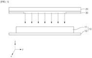
FIG. 1 , in theelectrode sheet 10 in which theelectrode slurry 12 is applied to thecurrent collector 12, the area around the boundary between a coated part to which the electrode slurry is applied and the non-coated part to which the electrode slurry is not applied is an area where a large number of thermal wrinkles occur. Since the drying speed of both edge areas in the width direction (y-axis direction) of the coated part is faster than the drying speed of the center area of the coated part, this deviation in drying speed causes thermal wrinkles, especially since the current collector expands as the temperature rises, the shrinkage of the electrode slurry and the expansion of the current collector work synergistically during drying, so the thermal wrinkles are aggravated. - In order to suppress this, an attempt is made to alleviate such thermal wrinkling phenomenon by disposing a
shield unit 30 at the lower part of the infrared heater of the electrode drying device, thereby controlling the position and area where the radiant heat emitted from the infrared heater is exposed to the electrode coated part. Referring toFIG. 1 , ashield unit 30 is disposed at the lower part of each of both sides of theinfrared heater 20, and a portion of the radiant heat emitted from theinfrared heater 20 is blocked by theshield unit 30. -
FIG. 2 is an enlarged view of a portion of a conventional shield unit. In the shield unit, an end of theshield 32 in the width direction y, which functions to block radiant heat, has a shape in which a planar shield is extended in a straight shape. Shields of this structure, when exposed to high temperature environments for extended periods of time, suffer from shield sagging due to the weight of the shield itself and thermal expansion.FIG. 3 illustrates this shield sagging phenomenon. If the shield sagging is severe, it may come into contact with the electrode slurry during drying, resulting in poor electrode quality. - Therefore, it is necessary to develop a technology for a shield unit that can prevent the shield sagging phenomenon of the shield unit.
- The present invention aims to provide an electrode drying device and an electrode drying method that prevents a sagging phenomenon of a shield unit installed in an electrode drying device in order to alleviate a thermal wrinkling phenomenon occurring around the boundary of a coated part and a non-coated part of an electrode sheet, ultimately improving the quality of the electrode.
- An electrode drying device according to an exemplary embodiment of the present invention is an electrode drying device that dries an electrode sheet with an electrode slurry applied to a sheet-type current collector, including an infrared heater for applying radiant heat to the electrode sheet, and a shield unit provided for blocking a portion of the radiant heat emitted from the infrared heater, wherein the shield unit includes: a shield including first and second blocking parts configured to block one side and the other side of the infrared heater in the longitudinal direction; and first and second connecting parts disposed to be spaced apart from each other for connecting the first and second blocking parts; and a base plate disposed on a lower surface of the shield to support the shield, wherein the shield includes a bending part shaped to be curved toward an upper part where the infrared heater is located.
- In an exemplary embodiment of the present invention, the shield may include a first bending part formed at the first connecting part and a second bending part formed at the second connecting part.
- In an exemplary embodiment of the present invention, the bending part may be spaced apart from a plane of the base plate, with a maximum spacing distance of 0.1 mm to 5 mm.
- In an exemplary embodiment of the present invention, the bending part may have a width of 5 mm to 30 mm at a position spaced 1 mm to 20 mm inwardly from an end of the shield.
- In an exemplary embodiment of the present invention, a cross-section of the spacing space between the bending part and the base plate may have a semicircular shape.
- In an exemplary embodiment of the present invention, a cross-section of the spacing space between the bending part and the base plate may have a triangular shape.
- In an exemplary embodiment of the present invention, a cross-section of the spacing space between the bending part and the base plate may have a quadrilateral shape.
- In an exemplary embodiment of the present invention, the base plate is in the shape of a square frame with a rectangular first through-hole in the center, wherein the ends of the two corner part of the base plate may each be bent upwardly.
- In an exemplary embodiment of the present invention, the shield may be in the shape of a square frame with a rectangular second through-hole in the center.
- In an exemplary embodiment of the present invention, the shield unit may further include a fixing clamp configured to attach and detach the shield unit to the infrared heater or its surroundings.
- In an exemplary embodiment of the present invention, the shield may be configured of a material of stainless steel having a thickness of 0.5 mm to 10 mm.
- In an exemplary embodiment of the present invention, the shield may be configured to be movably coupled to slide on the base plate.
- The electrode drying device according to an exemplary embodiment of the present invention may further include a transfer part for transferring an electrode sheet to be dried in one direction while supported, wherein the shield unit may be disposed between the infrared heater and the transfer part.
- The electrode drying device according to an exemplary embodiment of the present invention may further include a hot air drying means for blowing hot air onto the electrode sheet.
- An electrode drying method according to the present invention dries an electrode sheet using the electrode drying device.
- A shield unit according to the present invention has an effect of preventing a shield sagging phenomenon due to improved thermal fluidity by including a bending part in a part of the shield, and the drying device according to the present invention can reduce electrode failure due to shield sagging.
-
-
FIG. 1 is a conceptual diagram that illustrates the need for a shield unit. -
FIG. 2 is an enlarged view of a portion of a conventional shield unit. -
FIG. 3 is a diagram illustrating the problems of a conventional shield unit. -
FIG. 4 is a diagram illustrating a portion of a side of an electrode drying device according to an exemplary embodiment of the present invention. -
FIG. 5 is a side view of an electrode drying device according to an exemplary embodiment of the present invention. -
FIG. 6 is a front view of an electrode drying device according to an exemplary embodiment of the present invention. -
FIG. 7 is an exploded perspective view of a shield unit according to an exemplary embodiment of the present invention. -
FIG. 8 is a coupling diagram of a shield unit according to an exemplary embodiment of the present invention. -
FIG. 9 is a top view of a shield according to an exemplary embodiment of the present invention. -
FIG. 10 is a top view of a base plate according to an exemplary embodiment of the present invention. -
FIG. 11 is an enlarged view of a portion of a base plate according to an exemplary embodiment of the present invention. -
FIG. 12 is an enlarged view of a portion of a shield unit according to an exemplary embodiment of the present invention. -
FIG. 13 is a diagram of a bending part according to an exemplary embodiment of the present invention. -
FIG. 14 is a diagram of a bending part according to various exemplary embodiments of the present invention. - The present invention may have various modifications and various examples, and specific examples are illustrated in the drawings and described in detail in the description. However, it should be understood that the present invention is not limited to specific embodiments, and includes all modifications, equivalents or alternatives within the spirit and technical scope of the present invention.
- The terms "comprise," "include" and "have" are used herein to designate the presence of characteristics, numbers, steps, actions, components or members described in the specification or a combination thereof, and it should be understood that the possibility of the presence or addition of one or more other characteristics, numbers, steps, actions, components, members or a combination thereof is not excluded in advance.
- In addition, when a part of a layer, a film, a region or a plate is disposed "on" another part, this includes not only a case in which one part is disposed "directly on" another part, but a case in which a third part is interposed there between. In contrast, when a part of a layer, a film, a region or a plate is disposed "under" another part, this includes not only a case in which one part is disposed "directly under" another part, but a case in which a third part is interposed there between. In addition, in this application, "on" may include not only a case of disposed on an upper part but also a case of disposed on a lower part.
- In this specification, the x-axis is the direction in which the electrode sheet is transferred, the y-axis is the width direction of the electrode sheet or the longitudinal direction of the infrared heater, and the z-axis is the direction perpendicular to the plane of the electrode sheet, corresponding to the irradiation direction of the infrared light or the blowing direction of the hot air.
- The electrode drying device of the present invention is described below.
-
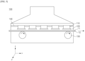
FIG. 4 is a diagram illustrating a portion of a side of an electrode drying device according to an exemplary embodiment of the present invention,FIG. 5 is a side view of an electrode drying device according to an exemplary embodiment of the present invention,FIG. 6 is a front view of an electrode drying device according to an exemplary embodiment of the present invention,FIG. 7 is an exploded perspective view of a shield unit according to an exemplary embodiment of the present invention, andFIG. 8 is a coupling diagram of a shield unit according to an exemplary embodiment of the present invention. - The
electrode sheet 10 to be dried by thedrying device 100 of the present invention may include a sheet-typecurrent collector 12, as shown inFIGS. 1 and5 , and anelectrode slurry 11 applied to at least one side of thecurrent collector 12. In other words, theelectrode sheet 10 of the present invention is manufactured by coating theelectrode slurry 11 on one or both sides of the sheet-type current collector to be transferred, and theelectrode slurry 11 of theelectrode sheet 10 thus manufactured is dried through theelectrode drying device 100 of the present invention. - An
electrode drying device 100 according to an exemplary embodiment of the present invention, which is a drying device for alleviating drying deviations between a center part in the width direction and both edge parts of an electrode slurry and alleviating a thermal wrinkling phenomenon due to thermal expansion of the current collector, may include aninfrared heater 110 for applying radiant heat to theelectrode sheet 10, ashield unit 120 provided for blocking a portion of the radiant heat emitted from theinfrared heater 110, and a transferringpart 130 for transferring the electrode sheet to be dried in one direction while being supported. - The
infrared heater 110 may be a drying means disposed on an upper part of theelectrode sheet 10, relative to a direction perpendicular to a plane of the electrode sheet 10 (z-axis direction), and configured to emit radiant heat toward theelectrode sheet 10 on the lower side. The infrared heater may include an infrared lamp (not shown) that irradiates infrared light, and a holder (not shown) that supports or holds the infrared lamp. The number and shape of the infrared heater is not particularly limited. When including a plurality of infrared heaters, the infrared heaters may be spaced apart from each other along the transfer direction (x-axis direction) of the electrode sheet. - The
shield unit 120 is installed at a proximate location of theinfrared heater 110, such as below theinfrared heater 110, in order to control the location and area of the region irradiated by the radiant heat emitted from theinfrared heater 110. The size and shape of theshield unit 120 is not particularly limited and may have a shape that corresponds to the size and shape of the infrared heater. For example, if the infrared heater is rod-shaped, theshield unit 120 may also be rod-shaped. - And, as shown in
FIGS. 4 and5 , in a structure in which a plurality ofinfrared heaters 110 are arranged along the transfer direction of theelectrode sheet 10, theshield unit 120 may also be arranged in pairs with theinfrared heaters 110. - The transferring
part 130 may include one or more transfer rollers, as means for transferring theelectrode sheet 10 in the transfer direction (x-axis direction). The transfer rollers support the electrode sheet, move the electrode sheet in the transfer direction by rotational motion, and may further include a motor (not shown) that applies a rotational force to the transfer rollers. - In addition, the
electrode drying device 100 of the present invention may further include a hot air drying means 140 for blowing hot air onto the electrode sheet. The hot air drying means is not particularly limited to any form as long as it can blow heated air toward the electrode sheet. An electrode drying device that includes a hot air drying means in addition to an infrared heater has the advantage of further increasing drying efficiency. -
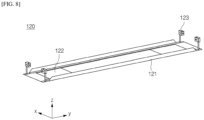
FIG. 7 is an exploded perspective view of a shield unit according to an exemplary embodiment of the present invention,FIG. 8 is a coupling diagram of a shield unit according to an exemplary embodiment of the present invention,FIG. 9 is a top view of a shield according to an exemplary embodiment of the present invention, andFIG. 10 is a top view of a base plate according to an exemplary embodiment of the present invention,FIG. 11 is an enlarged view of a portion of the base plate according to an exemplary embodiment of the present invention,FIG. 12 is an enlarged view of a portion of the shield unit according to an exemplary embodiment of the present invention,FIG. 13 is a diagram of a bending part according to an exemplary embodiment of the present invention, andFIG. 14 is a diagram of the bending part according to various exemplary embodiments of the present invention. - With reference to these drawings, a shield unit according to the present invention will be described in detail.
- A
shield unit 120 according to an exemplary embodiment of the present invention includes: ashield 122 including first andsecond blocking parts infrared heater 110; and a first and second connectingparts second blocking parts base plate 121 disposed on a lower surface of theshield 122 to support the shield, wherein theshield 122 includes a bending part B1, B2 bent toward an upper part where theinfrared heater 110 is located. - Referring to
FIG. 2 , aconventional shield 32 has an end that extends in a straight line in a plane without bending, but theshield 122 of the present invention includes a bending part B1, B2, as shown inFIG. 12 , and the shape of this bending part improves thermal fluidity in a high-temperature environment, and consequently alleviates the sagging phenomenon of the shield. - Referring to
FIGS. 7 and8 , andFIGS. 10 and11 , thebase plate 121 has a square frame shape with a rectangular first through-hole 121h in the center.
Thebase plate 121 functions to support theshield 122, and on thebase plate 121, theshield 122 is seated. - In one particular example, the
base plate 121 may include two corner parts bent upwardly for aligning the shield seated on the base plate. Referring toFIGS. 10 and11 , therectangular base plate 121 may have fourcorner parts 121a-121d, of which the ends of the twocorner parts - The
shield 122, which is seated on thebase plate 121, has first andsecond blocking parts second blocking parts infrared heater 110 so that a portion of the radiant heat emitted from theinfrared heater 110 is not transmitted to theelectrode sheet 10. - Referring to
FIG. 9 , theshield 122 has a square frame shape with a rectangular second through-hole 122h in the center. Centering on the second through-hole 122h, afirst blocking part 122a is located on the left, asecond blocking part 122b is located on the right, a first connectingpart 122c is located on the top, and a second connectingpart 122d is located on the bottom. - The first and
second blocking parts second blocking parts - The first and second connecting
parts third corner part 121c and thefourth corner part 121d of thebase plate 121, respectively, and have a predetermined width and extend along the longitudinal direction (y-axis direction) of the infrared heater. Within the spacing space between the first connectingpart 122c and the second connectingpart 122d, the second through-hole 122h is disposed. - Radiant heat emitted from the
infrared heater 110 passes through the second through-hole 122h and is irradiated onto theelectrode sheet 10. - The shield is preferably made of a stainless steel material that is not prone to thermal deformation in a high temperature environment of 100°C to 150°C, and the thickness may be 0.5mm to 10mm.
- In one particular example, the
shield 122 may be movably coupled to slide on thebase plate 121. - The
shield 122, according to one particular example, may include a first bending part B1 formed at the first connectingpart 122c and a second bending part B2 formed at the second connectingpart 122d. - The first and second bending parts B1, B2 extend along the longitudinal direction (y-axis direction) of the
shield 122, respectively, and may be formed in a region from one end to the other end of the first connectingpart 122c, and may be formed in a region from one end to the other end of the second connectingpart 122d. However, the embodiment of the bending parts B1, B2 of the present invention is not limited to this, but may be embodied in various forms. For example, the bending parts B1, B2 may be formed at the location shown inFIG. 9 , but their length may be 60% to 100% of the length L in the extending direction (y-axis length) of the first and second connectingparts - In addition, the formation locations of the bending parts B1, B2 may also be around the ends of the first and
second blocking parts FIG. 9 . - Referring to
FIGS. 12 and13 , the bending parts B1, B2 of the present invention are spaced apart from the plane of thebase plate 121 by a predetermined height in a plane-perpendicular direction (z-axis direction). In this case, the highest height H of the bending part, which is the maximum separation distance, may be 0.1 mm to 5 mm. - In addition, referring to
FIG. 13 , the bending parts B1, B2 may be configured to have a width W of 5 mm to 30 mm at a position spaced 1 mm to 20 mm inwardly from theend 122f of theshield 122. Here, the separation distance of 1 mm to 20 mm corresponds to D inFIG. 13 . - Referring to
FIG. 13 , in the bending part according to an exemplary embodiment of the present invention, a cross-section of the spacing space between the bending part B and thebase plate 121 may have a semicircular shape. - The curved shape of the bending part is not limited to this, and as shown in
FIG. 14 , the cross-section of the spacing space between the bending part B and thebase plate 121 may be triangular, trapezoidal, or even quadrilateral. The quadrilateral may include both a rectangle and a square. - Referring to the above diagrams, the
shield unit 120 according to an exemplary embodiment of the present invention may further include a fixingclamp 123 configured to attach and detach theshield unit 120 to theinfrared heater 110 or its surroundings. - The location, number, and the like of the fixing
clamp 123 are not particularly limited, as long as they are capable of fixing the shield unit, but the fixingclamp 123 according to an exemplary embodiment of the present invention may be provided one each around the four vertices of thebase plate 121 supporting theshield 122, so as to stably fix the rectangular-shapedshield unit 120 to theinfrared heater 110 or its surroundings. - A drying method of an electrode according to the present invention dries by using the electrode drying device.
- The electrode drying device according to the present invention, wherein a shield comprising a shield unit installed to block a portion of the radiant heat emitted from an infrared heater includes a bending part in a curved form, has the effect of improving the shield sagging phenomenon by suppressing the temperature rise of the shield in a high temperature environment, and the drying device and drying method according to the present invention can reduce electrode defects due to shield sagging.
- The shielding unit including the conventional shielding shown in
FIG. 2 was installed in the electrode drying device and the electrode sheets were dried for 30 days. - The shield unit was then removed and the maximum sagging length was measured where the shield sagged below the height of the base plate, with the results shown in Table 1.
- As shown in
FIG. 12 , a shield unit including a shield with a bending part was installed in an electrode drying device to dry the electrode sheet for 30 days. - The shield unit was then removed and the maximum sagging length was measured where the shield sagged below the height of the base plate, with the results shown in Table 1.
- For each of the shields of the Comparative Example and Example, DT_max was measured and the results are shown in Table 1. DT_max is the maximum temperature difference across the entire volume of the shield, with a smaller DT_max indicating favorable heat flow.
[Table 1] Maximum sagging length DT_max Comparative Example 4.11mm 2.704 Example 1.64mm 0.476 - Referring to Table 1, it can be seen that the shield including the bending part according to the present invention has improved thermal fluidity, which has the effect of improving the shield sagging phenomenon due to the accumulation of drying time. Accordingly, the electrode drying device of the present invention is expected to have the effect of reducing the risk of poor electrode quality.
-
- 10: ELECTRODE SHEET
- 11: ELECTRODE SLURRY
- 12: CURRENT COLLECTOR
- 20: INFRARED HEATER
- 30: SHIELD UNIT
- 100: ELECTRODE DRYING DEVICE
- 110: INFRARED HEATER
- 120: SHIELD UNIT
- 121: BASE PLATE
- 121h: FIRST THROUGH-HOLE
- 122: SHIELD
- 122a: FIRST BLOCKING PART
- 122b: SECOND BLOCKING PART
- 122c: FIRST CONNECTING PART
- 122d: SECOND CONNECTING PART
- B1: FIRST BENDING PART
- B2: SECOND BENDING PART
- 123: FIXING CLAMP
- 130: TRANSFERRING PART
- 140: HOT AIR DRYING MEANS
Claims (15)
- An electrode drying device that dries an electrode sheet with an electrode slurry applied to a sheet-type current collector, comprisingan infrared heater for applying radiant heat to the electrode sheet, and a shield unit provided for blocking a portion of the radiant heat emitted from the infrared heater, whereinthe shield unit comprises:a shield comprising first and second blocking parts configured to block one side and the other side of the infrared heater in the longitudinal direction; and first and second connecting parts connecting the first and second blocking parts and disposed to be spaced apart from each other; anda base plate disposed on a lower surface of the shield to support the shield, whereinthe shield comprises a bending part shaped to be curved toward an upper part where the infrared heater is located.
- The electrode drying device of claim 1, wherein the shield comprises
a first bending part formed at the first connecting part and a second bending part formed at the second connecting part. - The electrode drying device of claim 1, wherein
the bending part is spaced apart from a plane of the base plate, with a maximum spacing distance of 0.1 mm to 5 mm. - The electrode drying device of claim 1, wherein
the bending part has a width of 5 mm to 30 mm at a position spaced 1 mm to 20 mm inwardly from an end of the shield. - The electrode drying device of claim 1, wherein
a cross-section of the spacing space between the bending part and the base plate has a semicircular shape. - The electrode drying device of claim 1, wherein
a cross-section of the spacing space between the bending part and the base plate has a triangular shape. - The electrode drying device of claim 1, wherein
a cross-section of the spacing space between the bending part and the base plate has a quadrilateral shape. - The electrode drying device of claim 1, whereinthe base plate is in the shape of a square frame with a rectangular first through-hole in the center, whereinthe ends of the two corner parts of the base plate are each bent upwardly.
- The electrode drying device of claim 1, wherein
the shield is in the shape of a square frame with a rectangular second through-hole in the center. - The electrode drying device of claim 8, wherein the shield unit further comprises
a fixing clamp configured to attach and detach the shield unit to the infrared heater or its surroundings. - The electrode drying device of claim 1, wherein
the shield is configured of a material of stainless steel having a thickness of 0.5 mm to 10 mm. - The electrode drying device of claim 1, wherein
the shield is configured to be movably coupled to slide on the base plate. - The electrode drying device of claim 1, further comprising a transfer part for transferring an electrode sheet to be dried in one direction while supported, wherein
the shield unit is disposed between the infrared heater and the transfer part. - The electrode drying device of claim 1, further comprising a hot air drying means for blowing hot air onto the electrode sheet.
- An electrode drying method using the electrode drying device according to claim 1.
Applications Claiming Priority (2)
| Application Number | Priority Date | Filing Date | Title |
|---|---|---|---|
| KR1020220113035A KR20240034014A (en) | 2022-09-06 | 2022-09-06 | Electrode drying device and electrode drying method |
| PCT/KR2023/013191 WO2024053973A1 (en) | 2022-09-06 | 2023-09-04 | Electrode drying device and electrode drying method |
Publications (2)
| Publication Number | Publication Date |
|---|---|
| EP4394913A1 true EP4394913A1 (en) | 2024-07-03 |
| EP4394913A4 EP4394913A4 (en) | 2025-04-16 |
Family
ID=90191430
Family Applications (1)
| Application Number | Title | Priority Date | Filing Date |
|---|---|---|---|
| EP23863445.5A Pending EP4394913A4 (en) | 2022-09-06 | 2023-09-04 | Electrode drying device and electrode drying method |
Country Status (6)
| Country | Link |
|---|---|
| US (1) | US20260002731A1 (en) |
| EP (1) | EP4394913A4 (en) |
| JP (1) | JP7767591B2 (en) |
| KR (1) | KR20240034014A (en) |
| CN (1) | CN118043982A (en) |
| WO (1) | WO2024053973A1 (en) |
Family Cites Families (11)
| Publication number | Priority date | Publication date | Assignee | Title |
|---|---|---|---|---|
| FR2166542A5 (en) * | 1971-12-29 | 1973-08-17 | Bronzavia Sa | |
| JP2506835B2 (en) * | 1987-10-29 | 1996-06-12 | 松下電器産業株式会社 | Manufacturing method of solid electrolyte battery |
| JPH11325727A (en) * | 1998-05-13 | 1999-11-26 | Sky Alum Co Ltd | Far infrared dryer |
| CA2312213A1 (en) * | 2000-06-15 | 2001-12-15 | Hydro-Quebec | New process for preparing electrodes and electrolytes for li-ion batteries |
| JP5987373B2 (en) * | 2011-03-10 | 2016-09-07 | 東レ株式会社 | Coating film drying apparatus and drying method |
| JP5984643B2 (en) * | 2012-11-29 | 2016-09-06 | 株式会社メイコー | Electrode sheet drying apparatus and electrode sheet drying method |
| JP6524521B2 (en) * | 2015-06-25 | 2019-06-05 | パナソニックIpマネジメント株式会社 | Method and apparatus for manufacturing laminate |
| JP2022037762A (en) * | 2020-08-25 | 2022-03-09 | トヨタ自動車株式会社 | Temperature management system |
| KR102872101B1 (en) * | 2020-09-03 | 2025-10-15 | 주식회사 엘지에너지솔루션 | System for automatically controlling the drying of electrodes and method for automatically controlling the drying of electrodes |
| KR102883266B1 (en) * | 2020-12-09 | 2025-11-07 | 주식회사 엘지화학 | Electrode drying apparatus and electrode drying system having the same |
| KR102513516B1 (en) | 2021-02-05 | 2023-03-23 | 동성이엔지 주식회사 | Multi-layer hairpin alignment jig for electric vehicle drive motor |
-
2022
- 2022-09-06 KR KR1020220113035A patent/KR20240034014A/en active Pending
-
2023
- 2023-09-04 JP JP2024517546A patent/JP7767591B2/en active Active
- 2023-09-04 US US18/695,564 patent/US20260002731A1/en active Pending
- 2023-09-04 EP EP23863445.5A patent/EP4394913A4/en active Pending
- 2023-09-04 WO PCT/KR2023/013191 patent/WO2024053973A1/en not_active Ceased
- 2023-09-04 CN CN202380013613.6A patent/CN118043982A/en active Pending
Also Published As
| Publication number | Publication date |
|---|---|
| JP2024535317A (en) | 2024-09-30 |
| JP7767591B2 (en) | 2025-11-11 |
| US20260002731A1 (en) | 2026-01-01 |
| CN118043982A (en) | 2024-05-14 |
| EP4394913A4 (en) | 2025-04-16 |
| WO2024053973A1 (en) | 2024-03-14 |
| KR20240034014A (en) | 2024-03-13 |
Similar Documents
| Publication | Publication Date | Title |
|---|---|---|
| KR102342736B1 (en) | Producing method of mask integrated frame | |
| US11876163B2 (en) | Sizing roller apparatus for folding process of battery cell | |
| KR101782048B1 (en) | Apparatus for heating blank portion used for manufacturing electrode of secondary battery | |
| US20260002731A1 (en) | Electrode Drying Device and Electrode Drying Method | |
| KR102842440B1 (en) | Electrode drying device | |
| KR20240034011A (en) | Electrode drying device and electrode drying method | |
| EP3399069B1 (en) | Crucible for accommodating and heating material, and system comprising arranged crucible and heater | |
| KR100232306B1 (en) | Base plate heating apparatus | |
| JP3950424B2 (en) | Heat treatment equipment | |
| CN215163089U (en) | Film coating carrier plate | |
| KR102314853B1 (en) | Mask for forming oled picture element and mask supporting tray | |
| KR102679829B1 (en) | Boat for semiconductor processing | |
| JP4869952B2 (en) | Heat treatment equipment | |
| CN222557045U (en) | Coating film carrier plate and coating film equipment | |
| CN220012803U (en) | Multi-point comprehensive supporting PECVD carrier plate | |
| JP2002299431A (en) | Substrate storage cassette | |
| KR102743405B1 (en) | Integrated support for holding substrate and heater, and heat treatment apparatus for substrate including the same | |
| US20230366623A1 (en) | Electrode Drying Device | |
| JP3578405B2 (en) | heating furnace | |
| CN223292626U (en) | A carrier frame | |
| KR102910529B1 (en) | Electrode drying device | |
| JP7743990B2 (en) | Ultra-small cell assembly device and electrode stack manufacturing method using the same | |
| JP7562593B2 (en) | Manufacturing method of sealed battery | |
| CN214950220U (en) | Baking jig for strip-shaped ultrathin copper sheet | |
| KR20220081839A (en) | Electrode drying apparatus and electrode drying system having the same |
Legal Events
| Date | Code | Title | Description |
|---|---|---|---|
| STAA | Information on the status of an ep patent application or granted ep patent |
Free format text: STATUS: THE INTERNATIONAL PUBLICATION HAS BEEN MADE |
|
| PUAI | Public reference made under article 153(3) epc to a published international application that has entered the european phase |
Free format text: ORIGINAL CODE: 0009012 |
|
| STAA | Information on the status of an ep patent application or granted ep patent |
Free format text: STATUS: REQUEST FOR EXAMINATION WAS MADE |
|
| 17P | Request for examination filed |
Effective date: 20240325 |
|
| AK | Designated contracting states |
Kind code of ref document: A1 Designated state(s): AL AT BE BG CH CY CZ DE DK EE ES FI FR GB GR HR HU IE IS IT LI LT LU LV MC ME MK MT NL NO PL PT RO RS SE SI SK SM TR |
|
| A4 | Supplementary search report drawn up and despatched |
Effective date: 20250317 |
|
| RIC1 | Information provided on ipc code assigned before grant |
Ipc: F26B 13/14 20060101ALI20250311BHEP Ipc: F26B 25/16 20060101ALI20250311BHEP Ipc: F26B 21/00 20060101ALI20250311BHEP Ipc: F26B 3/30 20060101ALI20250311BHEP Ipc: H01M 4/04 20060101AFI20250311BHEP |
|
| DAV | Request for validation of the european patent (deleted) | ||
| DAX | Request for extension of the european patent (deleted) |