EP4394815A1 - Diagnostic system for transformer - Google Patents
Diagnostic system for transformer Download PDFInfo
- Publication number
- EP4394815A1 EP4394815A1 EP22859546.8A EP22859546A EP4394815A1 EP 4394815 A1 EP4394815 A1 EP 4394815A1 EP 22859546 A EP22859546 A EP 22859546A EP 4394815 A1 EP4394815 A1 EP 4394815A1
- Authority
- EP
- European Patent Office
- Prior art keywords
- temperature
- winding
- transformer
- diagnostic system
- oil
- Prior art date
- Legal status (The legal status is an assumption and is not a legal conclusion. Google has not performed a legal analysis and makes no representation as to the accuracy of the status listed.)
- Pending
Links
Images


Classifications
-
- H—ELECTRICITY
- H01—ELECTRIC ELEMENTS
- H01F—MAGNETS; INDUCTANCES; TRANSFORMERS; SELECTION OF MATERIALS FOR THEIR MAGNETIC PROPERTIES
- H01F27/00—Details of transformers or inductances, in general
- H01F27/08—Cooling; Ventilating
- H01F27/10—Liquid cooling
- H01F27/12—Oil cooling
-
- G—PHYSICS
- G01—MEASURING; TESTING
- G01R—MEASURING ELECTRIC VARIABLES; MEASURING MAGNETIC VARIABLES
- G01R31/00—Arrangements for testing electric properties; Arrangements for locating electric faults; Arrangements for electrical testing characterised by what is being tested not provided for elsewhere
- G01R31/50—Testing of electric apparatus, lines, cables or components for short-circuits, continuity, leakage current or incorrect line connections
- G01R31/62—Testing of transformers
-
- G—PHYSICS
- G01—MEASURING; TESTING
- G01R—MEASURING ELECTRIC VARIABLES; MEASURING MAGNETIC VARIABLES
- G01R31/00—Arrangements for testing electric properties; Arrangements for locating electric faults; Arrangements for electrical testing characterised by what is being tested not provided for elsewhere
- G01R31/12—Testing dielectric strength or breakdown voltage ; Testing or monitoring effectiveness or level of insulation, e.g. of a cable or of an apparatus, for example using partial discharge measurements; Electrostatic testing
- G01R31/1227—Testing dielectric strength or breakdown voltage ; Testing or monitoring effectiveness or level of insulation, e.g. of a cable or of an apparatus, for example using partial discharge measurements; Electrostatic testing of components, parts or materials
- G01R31/1263—Testing dielectric strength or breakdown voltage ; Testing or monitoring effectiveness or level of insulation, e.g. of a cable or of an apparatus, for example using partial discharge measurements; Electrostatic testing of components, parts or materials of solid or fluid materials, e.g. insulation films, bulk material; of semiconductors or LV electronic components or parts; of cable, line or wire insulation
-
- H—ELECTRICITY
- H01—ELECTRIC ELEMENTS
- H01F—MAGNETS; INDUCTANCES; TRANSFORMERS; SELECTION OF MATERIALS FOR THEIR MAGNETIC PROPERTIES
- H01F27/00—Details of transformers or inductances, in general
- H01F27/28—Coils; Windings; Conductive connections
- H01F27/32—Insulating of coils, windings, or parts thereof
- H01F27/324—Insulation between coil and core, between different winding sections, around the coil; Other insulation structures
-
- H—ELECTRICITY
- H01—ELECTRIC ELEMENTS
- H01F—MAGNETS; INDUCTANCES; TRANSFORMERS; SELECTION OF MATERIALS FOR THEIR MAGNETIC PROPERTIES
- H01F27/00—Details of transformers or inductances, in general
- H01F27/40—Structural association with built-in electric component, e.g. fuse
- H01F27/402—Association of measuring or protective means
-
- H—ELECTRICITY
- H01—ELECTRIC ELEMENTS
- H01F—MAGNETS; INDUCTANCES; TRANSFORMERS; SELECTION OF MATERIALS FOR THEIR MAGNETIC PROPERTIES
- H01F27/00—Details of transformers or inductances, in general
- H01F27/40—Structural association with built-in electric component, e.g. fuse
- H01F27/402—Association of measuring or protective means
- H01F2027/404—Protective devices specially adapted for fluid filled transformers
-
- H—ELECTRICITY
- H01—ELECTRIC ELEMENTS
- H01F—MAGNETS; INDUCTANCES; TRANSFORMERS; SELECTION OF MATERIALS FOR THEIR MAGNETIC PROPERTIES
- H01F27/00—Details of transformers or inductances, in general
- H01F27/40—Structural association with built-in electric component, e.g. fuse
- H01F27/402—Association of measuring or protective means
- H01F2027/406—Temperature sensor or protection
Definitions
- patent document1 uses a temperature sensor at the bottom and moisture content to estimate the degree of polymerization.
- the amount of moisture in oil can vary depending on its temperature, if the moisture content is measured at the bottom of the transformer, the moisture content will be lower than during operation, and the error in the degree of polymerization estimation value may be larger.
- the degree of polymerization is estimated by the temperature sensor at the bottom and the moisture content, the error in the estimated degree of polymerization value may become larger.
- the purpose of this invention is to provide a transformer diagnostic system that enables highly accurate diagnosis.
- Converter6 performs data conversion of detection data from hydrogen detector2, temperature detectors, and current detector4 for processing on an arithmetic pc (personal computer)7.
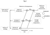
- the solid circled area indicates the area where the temperature is actually measured. Dotted circles indicate areas where temperatures are calculated from the measured temperatures.
- the average winding temperature in Fig.2 can be measured by performing a temperature test before the transformer operation.
- the maximum oil temperature and the bottom oil temperature can be measured during the operation of the transformer from the temperature detector of the upper insulating oil and the temperature detector of the lower insulating oil, respectively, during operation of the transformer.
- the processing unit of arithmetic PC7 calculates the "average winding upper temperature” from the measured upper oil temperature(maximum oil temperature) and the “average temperature difference between winding and oil” ⁇ wo .
- the "average winding top temperature” can be calculated from the measured temperatures. From information such as the "average winding top temperature” and the measured upper oil temperature(maximum oil temperature), the processing unit of the arithmetic PC7 can accurately estimate the maximum winding temperature.
- the actual degradation of the insulating paper is also measured by collecting and analyzing a sample of insulating paper from the insulated paper pockets attached to the top of the transformer1 to measure the average degree of polymerization. If the lifetime estimation does not agree with the analysis results, etc., the average degree of polymerization measured is used as the corrected equation2, and the processing unit of the arithmetic PC7 in this example performs the estimation calculation according to the corrected equation: In this way, the system can be doubly monitored by on-line and off-line monitoring. Such a configuration allows a more reliable diagnostic system to be configured.
- a hydrogen detector2 is installed in the lower part of the tank of the transformer! to prevent a serious accident from occurring due to a sudden abnormality such as local heating that is left unnoticed.
- the processing apparatus of the arithmetic PC7 diagnoses an abnormality of the transformer by determining that the hydrogen component acquired from the hydrogen detector2 exceeds a predetermined value (threshold).
- the touch panels obtains detection data such as temperature at the top and bottom of the insulating oil, hydrogen, and load current via converter6. The user can monitor these detection data with the touch panels.
- First wireless communication equipments and second wireless communication equipment11 communicate data between touch panels and data server10.
- the data server10 Based on the detection data from the transformer1 obtained from the second wireless communication equipment11, the data server10 performs the same as the arithmetic PC7 in example! to determine the abnormality of the transformer and to diagnose the remaining life of the transformer.
Landscapes
- Engineering & Computer Science (AREA)
- Power Engineering (AREA)
- Physics & Mathematics (AREA)
- General Physics & Mathematics (AREA)
- Housings And Mounting Of Transformers (AREA)
Abstract
Description
- This invention relates to a transformer diagnostic system.
- As a technique for diagnosing transformer anomalies, patent document1 uses a temperature sensor at the bottom and moisture content to estimate the degree of polymerization.
- The patent document2 monitors the load factor and other temperature information without incorporating it by means of upper and lower temperature sensors.
- The patent document3 diagnoses deterioration by temperature rise.
-
- [patent document1]
Japanese unexamined patent publication Tokkai2019-102694 - [patent document2]
Japanese unexamined patent publication Tokkaihei5-283240 - [Patent document3]
Japanese unexamined patent publication Tokkai2006-24800 - Since the amount of moisture in oil can vary depending on its temperature, if the moisture content is measured at the bottom of the transformer, the moisture content will be lower than during operation, and the error in the degree of polymerization estimation value may be larger. In patent document1, where the degree of polymerization is estimated by the temperature sensor at the bottom and the moisture content, the error in the estimated degree of polymerization value may become larger.
- There is a time constant between the winding and the oil, and that time constant varies depending on the oil type and winding structure. The temperature rise of the winding is key in considering damage to the insulation paper, and the monitoring of abnormal diagnosis is insufficient in patent document2, which monitors without incorporating the load factor.
- Patent documents diagnoses abnormalities mainly by temperature rise, but the parameters that determine the life of the transformer should consider abnormality diagnosis for other factors such as deterioration of insulating oil and the presence or absence of discharge in addition to the deterioration of insulating paper.
- The techniques in patent document1, patent document2, and patent documents are not sufficient to diagnose the lifetime of a transformer with high accuracy.
- The purpose of this invention is to provide a transformer diagnostic system that enables highly accurate diagnosis.
- One example of this invention is a transformer diagnostic system having an insulating oil and a winding comprising a detection part detects a temperature at the top and bottom of the insulating oil and hydrogen, an arithmetic unit determines abnormality based on the detected values from the detection part.
- According to the present invention, it is possible to realize a diagnostic system for transformer that can perform highly accurate diagnosis.
-
- [
Fig.1 ] This diagram illustrates the transformer and diagnostic system in example1. - [
Fig.2 ] This figure shows the relationship between winding temperature and oil temperature in example1. - [
Fig.3 ] This diagram illustrates the transformer and diagnostic system in example2. - The following is an example of the invention, illustrated with drawings.
-
Fig.1 is a configuration diagram illustrating the transformer and diagnostic system in example1. - The transformer1 is an oil-filled transformer with an iron core, a winding attached to the iron core and insulated by insulation paper (winding insulation paper), and insulating oil that soaks the winding and iron core, although the figure is omitted.
- Hydrogen detector2 detects hydrogen gas components based on data from a sensor that detects hydrogen gas components in the insulating oil at the bottom of transformer1. Here, it is also the detector that detects the temperature in the lower part of the insulating oil of transformer1. The hydrogen detector and the temperature detector for detecting the temperature at the bottom of the transformer! can be separate sensors.
- The temperature detector3 detects temperature based on data from a temperature sensor (such as a resistance thermometer) that detects the temperature at the top of the insulating oil of the transformer1.
- The current detector4 detects the load current (secondary current) flowing in the load.
- Converter6 performs data conversion of detection data from hydrogen detector2, temperature detectors, and current detector4 for processing on an arithmetic pc (personal computer)7.
- The arithmetic PC7 (arithmetic section) is a computer device equipped with a processor (processing unit) such as a CPU, main memory, memory device, communication device, etc., and processes various types of information. The processor (processing unit) of the PC7 executes the operations described below to diagnose abnormalities in the transformer and to predict its service life.
- This example transformer diagnostic system comprising a temperature detector2 that detects hydrogen and the temperature of the bottom part of the insulating oil, a detector3 that detects the temperature of the top part of the insulating oil, a current detector (CT)4 that detects the load current (secondary current) flowing in the load, an insulated paper pockets that takes samples of the insulating paper, a converters that converts the data, and an arithmetic PC7 that performs diagnostics and life prediction of the transformer.
- The diagnostic system of the transformer in this example measures the maximum winding temperature at the load factor, upper oil temperature, and lower oil temperature, and acquires the temperature history information by wired or wireless communication with an arithmetic PC7. At the same time, the arithmetic PC7 obtains information from the hydrogen sensor and diagnoses abnormalities based on its behavior. The load factor can be calculated from the load current from current detector4. The current to be detected is not limited to the load current, but the load current can be detected from the primary current of the transformer.
- The maximum winding temperature θH is defined by the following equation1 (Transformer Reliability Investigation Technical Committee, "Oil-immersed transformer operation guidelines," IEEJ Technical Report (Part 1) No. 143, November 1986, p. 1-2) .
[Number 1]
whereas, - θH : maximum winding temperature (°C)
- θa : ambient temperature (°C) (cooling air or cooling water temperature)
- θ0N: maximum oil temperature rise at rated load (K)
- θgN: Difference between maximum winding temperature and maximum oil temperature at rated load (K)
- K: Ratio of actual load P to rated load PN (in this case, load factor)
- R: Ratio of load loss to no load loss at rated load (here R=Wc (load loss)/Wi (no load loss))
- m: Constant determined by the cooling method
- n: Constant determined by the cooling method
- The parameters in equation1 that can be directly measured are θa and K. The parameters that are transformer-specific and can be specified in the shipment are θ0N, R, m, and n. Thus, the unknown value is θgN, and this estimation technique has been defined in various ways.
- Many techniques were employed to estimate using pre-measured values, but in the case of new designs, there was a problem that the previous knowledge was not utilized and differed from the results of the pre-measurement.
- In this example, the maximum winding temperature can be estimated with high accuracy in addition to estimation by machine learning by analyzing the parameters attributed to them, in addition to the actual measurement results.
-
Fig.2 shows the relationship between winding temperature and insulating oil temperature in example1. - The vertical axis in
Fig.2 shows the winding height of transformer1, and the horizontal axis shows the temperature rise of transformer1. - The solid circled area indicates the area where the temperature is actually measured. Dotted circles indicate areas where temperatures are calculated from the measured temperatures.
- The average winding temperature in
Fig.2 can be measured by performing a temperature test before the transformer operation. The maximum oil temperature and the bottom oil temperature can be measured during the operation of the transformer from the temperature detector of the upper insulating oil and the temperature detector of the lower insulating oil, respectively, during operation of the transformer. - The arithmetic PC7 processor calculates the average oil temperature from the measured upper oil temperature, lower (bottom) oil temperature, and the known winding height, and calculates the "average temperature difference between winding and oil" Δθwo from the difference between the measured average winding temperature and the average oil temperature.
- The processing unit of arithmetic PC7 then calculates the "average winding upper temperature" from the measured upper oil temperature(maximum oil temperature) and the "average temperature difference between winding and oil" Δθwo. The "average winding top temperature" can be calculated from the measured temperatures. From information such as the "average winding top temperature" and the measured upper oil temperature(maximum oil temperature), the processing unit of the arithmetic PC7 can accurately estimate the maximum winding temperature.
- Until now, the maximum oil temperature of the transformer and the average winding temperature have usually been measured, and the difference between the maximum point oil temperature and the maximum winding temperature was defined as 15°C. Different oil types and designs cause changes in the slope of the winding temperature rise and the slope of the oil temperature rise, resulting in cases where this value cannot be applied as it is.
- The processing unit of arithmetic PC7 in this example measures the oil temperature at the top and bottom, calculates the average oil temperature from the winding height information, and takes the difference from the average winding temperature obtained by actual measurement, so that the aforementioned "difference between the maximum winding temperature at rated load and the maximum oil temperature" θgN can be defined based on actual measurement rather than a constant 15°C.
- The arithmetic PC7 processor in this example can then calculate the difference θgN between the maximum oil temperature and the maximum winding temperature according to the slope of the winding temperature rise and the slope of the oil temperature rise for different oil types and designs. The maximum winding temperature θH can then be calculated from equation1 with higher accuracy.
- Furthermore, the processing unit of arithmetic PC7 in this example uses multiple regression curves to estimate the maximum winding temperature from information on various parameters (oil type, capacity, winding height, number of cooling ducts, wire cross-sectional area, wire shape, loss, etc.) determined during design, actual upper oil temperature and lower (bottom) oil temperature, and average winding temperature, using machine the maximum winding temperature is estimated by machine learning. The estimated maximum winding temperature is reflected in the new design to enable highly accurate life prediction at the design stage.
- Using the maximum winding temperature obtained above, the arithmetic PC7 processor in this example predicts the life of the transformer. The life of the transformer is defined as the degradation of the insulation paper and can be approximated by the Arrhenius law using the Montsinger equation within the temperature range of 80°C to 150°C and the following equation2 can be derived by defining it by the.6°C half rule.
[Number 2]
whereas, - Y0: Life expectancy when continuously operated at the highest point temperature of 95°C (25 to 30 years)
- Y: Life span when continuously operated at the highest point temperature θ
- θ: maximum point temperature θ (can be defined by maximum winding temperature θH)
- The processing unit of the arithmetic PC7 in this example calculates Y/Y0 according to equation2. Equations allows the remaining life of the transformer to be estimated from the information of the actual thermal history used.
- Furthermore, the actual degradation of the insulating paper is also measured by collecting and analyzing a sample of insulating paper from the insulated paper pockets attached to the top of the transformer1 to measure the average degree of polymerization. If the lifetime estimation does not agree with the analysis results, etc., the average degree of polymerization measured is used as the corrected equation2, and the processing unit of the arithmetic PC7 in this example performs the estimation calculation according to the corrected equation: In this way, the system can be doubly monitored by on-line and off-line monitoring. Such a configuration allows a more reliable diagnostic system to be configured.
- In this example, a hydrogen detector2 is installed in the lower part of the tank of the transformer! to prevent a serious accident from occurring due to a sudden abnormality such as local heating that is left unnoticed. The processing apparatus of the arithmetic PC7 diagnoses an abnormality of the transformer by determining that the hydrogen component acquired from the hydrogen detector2 exceeds a predetermined value (threshold).
- Hydrogen is the cause of all abnormal phenomena and exerts its effects on discharge, heating, and deterioration of insulation paper. In some cases, the degradation of insulation paper can be measured using the moisture content in oil as a proxy, but in this case, if the temperature at the time of collection changes, the saturated moisture content in the oil will differ, and the deposited moisture will migrate to the insulation paper, so there is a risk of misjudging the measurement results. On the other hand, in the case of hydrogen, which is a gas, changes in solubility due to changes in temperature exist, but the changes are several times smaller than those of water content, so the accuracy of analysis is dramatically improved.
- The above-mentioned transformer detection data is imported into an arithmetic PC7 through converter6, and various calculations are performed to determine abnormalities in the transformer and to diagnose its remaining life.
- According to this example, it is possible to realize a transformer's diagnostic system that can perform highly accurate diagnosis.
-
Fig.3 is a configuration diagram illustrating the transformer and diagnostic system in example2. - In example2, the touch panels, first wireless communication equipment9, second wireless communication equipment11, and data server10 are provided. The
data server 10 can diagnose the abnormalities of the transformer and predict the service life of the transformer via the first wireless communication equipments and second wireless communication equipment11 without arithmetic PC7 in example1. In this example, detection data such as temperature at the top and bottom of the insulating oil, hydrogen, and load current can be stored in the data server10. Hereinafter, explanations of the same items as in example1 will be omitted. - The touch panels obtains detection data such as temperature at the top and bottom of the insulating oil, hydrogen, and load current via converter6. The user can monitor these detection data with the touch panels.
- First wireless communication equipments and second wireless communication equipment11 communicate data between touch panels and data server10.
- Based on the detection data from the transformer1 obtained from the second wireless communication equipment11, the data server10 performs the same as the arithmetic PC7 in example! to determine the abnormality of the transformer and to diagnose the remaining life of the transformer.
- According to this example, in addition to the effects of .example 1, the detection data of multiple transformers can be stored in
data server 10, and the diagnosis of each transformer can be. centrally managed. -
- 1:
- transformer
- 2:
- hydrogen detector
- 3:
- temperature detector
- 4:
- current detector
- 5:
- insulated paper pocket
- 6:
- converter
- 7:
- arithmetic PC
- 8:
- touch panel
- 9:
- first wireless communication equipment
- 10:
- data server
- 11:
- second wireless communication equipment
Claims (9)
- A transformer diagnostic system having an insulating oil and a winding comprising:a detection part detects a temperature at the top and bottom of the insulating oil and hydrogen,an arithmetic unit determines abnormality based on the detected valu es from the detection part.
- A transformer diagnostic system described in claim 1 comprising:a current detector detects the load current flowing in the winding,the arithmetic unit calculates the load factor from the detected load current value.
- A transformer diagnostic system described in claim 1 comprising:hydrogen and lower oil temperatures are detected in the same detector,the arithmetic unit determines an abnormality when the amount of hydrogen detected exceeds a predetermined threshold value.
- A transformer diagnostic system described in claim 1 comprising:the arithmetic unitcalculates average oil temperature from the upper and lower insulating oil,calculates the average temperature difference between the winding and the insulating oil from the average winding temperature and the average oil temperature,calculates the average temperature of the upper part of the winding from the average temperature difference and the temperature of upper part of the insulating oil.
- A transformer diagnostic system described in claim 4 comprising:the arithmetic unit calculate a maximum winding temperature,estimates the remaining life of the transformer from the calculated maximum winding point temperature.
- A transformer diagnostic system described in claim 4 comprising:
the arithmetic unit estimates a maximum winding temperature from the parameter determined at the time of design. - A transformer diagnostic system described in claim 1 comprising:an insulated paper pocket,the arithmetic unit estimates remaining life of the transformer based on the results of analyzing the insulating paper collected from the insulating paper pocket.
- A transformer diagnostic system described in claim 1 comprising:an iron core,a winding attached to the iron core and insulated by insulating paper,and insulating oil for immersing the winding and iron core.
- A transformer diagnostic system having an insulating oil and a winding comprising:a communication equipment transmits detected temperature data of the upper and bottom part of the insulating oil and the hydrogen detection data,a data processing unit receives the detected data from the communication equipment,the data processing unit diagnoses an abnormality based on the detection data.
Applications Claiming Priority (2)
| Application Number | Priority Date | Filing Date | Title |
|---|---|---|---|
| JP2021135779A JP7518046B2 (en) | 2021-08-23 | 2021-08-23 | Transformer diagnostic system |
| PCT/JP2022/017216 WO2023026578A1 (en) | 2021-08-23 | 2022-04-07 | Diagnostic system for transformer |
Publications (2)
| Publication Number | Publication Date |
|---|---|
| EP4394815A1 true EP4394815A1 (en) | 2024-07-03 |
| EP4394815A4 EP4394815A4 (en) | 2025-12-10 |
Family
ID=85322661
Family Applications (1)
| Application Number | Title | Priority Date | Filing Date |
|---|---|---|---|
| EP22859546.8A Pending EP4394815A4 (en) | 2021-08-23 | 2022-04-07 | TRANSFORMER DIAGNOSTIC SYSTEM |
Country Status (5)
| Country | Link |
|---|---|
| US (1) | US20240288512A1 (en) |
| EP (1) | EP4394815A4 (en) |
| JP (1) | JP7518046B2 (en) |
| CN (1) | CN117529787A (en) |
| WO (1) | WO2023026578A1 (en) |
Families Citing this family (1)
| Publication number | Priority date | Publication date | Assignee | Title |
|---|---|---|---|---|
| CN118818378B (en) * | 2024-09-18 | 2024-12-24 | 江苏林达鸿利电气有限公司 | A transformer withstand voltage test device |
Family Cites Families (12)
| Publication number | Priority date | Publication date | Assignee | Title |
|---|---|---|---|---|
| JPS5818909A (en) * | 1981-07-27 | 1983-02-03 | Shikoku Electric Power Co Inc | Automatic abnormality diagnosis device for oil-filled electrical equipment |
| JPH05283240A (en) * | 1992-04-01 | 1993-10-29 | Toshiba Corp | Oil-filled transformer |
| JPH07297038A (en) * | 1994-04-20 | 1995-11-10 | Hitachi Ltd | Internal abnormality detection device and internal abnormality detection method for electric equipment |
| JP4125907B2 (en) * | 2002-03-28 | 2008-07-30 | 株式会社ダイヘン | Degradation diagnosis device for oil-filled transformer |
| JP2005073478A (en) * | 2003-08-28 | 2005-03-17 | Tm T & D Kk | Equipment monitoring device and equipment monitoring system |
| JP2006024800A (en) * | 2004-07-09 | 2006-01-26 | Aichi Electric Co Ltd | Oil-immersed transformer remaining life/anomaly diagnostic system |
| JP5234440B2 (en) * | 2010-02-17 | 2013-07-10 | 三菱電機株式会社 | Oil-filled electrical equipment life diagnosis device, oil-filled electrical equipment life diagnosis method, oil-filled electrical equipment deterioration suppression device, and oil-filled electrical equipment deterioration control method |
| MX377612B (en) * | 2014-07-10 | 2025-03-05 | Prolec Ge Int S De R L De C V | Electronic device for online monitoring of the moisture content of the paper of a potential transformer subjected to overloading, diagnosis of the safe operating time therein, and corresponding method |
| JP6803025B2 (en) * | 2017-03-06 | 2020-12-23 | 東北電力株式会社 | Remaining life diagnosis method and diagnostic equipment for oil-immersed transformers |
| JP7048284B2 (en) | 2017-12-05 | 2022-04-05 | 株式会社東光高岳 | Transformer diagnostic system, transformer diagnostic method, and transformer |
| JP6969721B2 (en) * | 2017-12-30 | 2021-11-24 | ヒタチ・エナジー・スウィツァーランド・アクチェンゲゼルシャフトHitachi Energy Switzerland Ag | System for sensor utilization in transformer cooling circuit |
| US12020856B2 (en) * | 2018-04-20 | 2024-06-25 | Siemens Energy Global GmbH & Co. KG | Sensformer |
-
2021
- 2021-08-23 JP JP2021135779A patent/JP7518046B2/en active Active
-
2022
- 2022-04-07 EP EP22859546.8A patent/EP4394815A4/en active Pending
- 2022-04-07 WO PCT/JP2022/017216 patent/WO2023026578A1/en not_active Ceased
- 2022-04-07 CN CN202280043863.XA patent/CN117529787A/en active Pending
- 2022-04-07 US US18/572,335 patent/US20240288512A1/en active Pending
Also Published As
| Publication number | Publication date |
|---|---|
| JP7518046B2 (en) | 2024-07-17 |
| WO2023026578A1 (en) | 2023-03-02 |
| CN117529787A (en) | 2024-02-06 |
| US20240288512A1 (en) | 2024-08-29 |
| JP2023030570A (en) | 2023-03-08 |
| EP4394815A4 (en) | 2025-12-10 |
Similar Documents
| Publication | Publication Date | Title |
|---|---|---|
| Sun et al. | A review of dissolved gas analysis in power transformers | |
| US6446027B1 (en) | Intelligent analysis system and method for fluid-filled electrical equipment | |
| US20050223782A1 (en) | Transformer monitoring system | |
| US20190056446A1 (en) | Method and system for assessment of fault severity, risk exposure, and gassing status for liquid-filled high-voltage apparatus | |
| CN114638280A (en) | Explosion-proof motor bearing temperature anomaly monitoring system based on local equipment network | |
| CN1292491A (en) | Fluid-filled electric equipment intelligent analytical system and method | |
| KR20110108343A (en) | Bushing Diagnosis | |
| CN106021759B (en) | Transformer fault recognition methods and system | |
| EP4394815A1 (en) | Diagnostic system for transformer | |
| KR101494382B1 (en) | Diagnosis method and apparatus of transformer oil | |
| CN115864310A (en) | Multi-parameter fusion power transformer defect identification, state classification and active safety protection method | |
| CN119534978B (en) | Residual current monitoring method and device | |
| JPH0794334A (en) | Deterioration diagnostic system and life predictive system of oil-immersed transformer | |
| KR102862490B1 (en) | Determining the condition of electrical equipment using fluctuations in diagnostic parameter prediction errors. | |
| RU82867U1 (en) | DIAGNOSTIC SYSTEM FOR OIL-FILLED MEASURING TRANSFORMERS | |
| KR100901855B1 (en) | A medium on which a three-phase alternating current rotating device insulation state diagnosis method and a computer readable program for executing the method are recorded. | |
| CN108375537A (en) | Insulation life detection method for marine cables based on maximum mass reduction rate | |
| CN119757905A (en) | Transformer operation monitoring method, device, system and storage medium | |
| Roizman et al. | Neuro-fuzzy computing for large power transformers monitoring and diagnostics | |
| Thango et al. | Empirical Based Approaches to Evaluating the Residual Life for Oil-Immersed Transformers—A Case Study | |
| Lozanov | Assessment of the technical condition of electric contact joints using thermography | |
| CN120750028B (en) | A power equipment monitoring, analysis and early warning system | |
| CN115524536B (en) | Method, device and system for testing direct-current resistance and evaluating state of dry-type reactor | |
| RU2133043C1 (en) | Method of diagnostics of thyristor converter | |
| KR20170038347A (en) | Apparatus and method for predicting water absorption of insulating material in water-cooled power gernerator stator windings |
Legal Events
| Date | Code | Title | Description |
|---|---|---|---|
| STAA | Information on the status of an ep patent application or granted ep patent |
Free format text: STATUS: THE INTERNATIONAL PUBLICATION HAS BEEN MADE |
|
| PUAI | Public reference made under article 153(3) epc to a published international application that has entered the european phase |
Free format text: ORIGINAL CODE: 0009012 |
|
| STAA | Information on the status of an ep patent application or granted ep patent |
Free format text: STATUS: REQUEST FOR EXAMINATION WAS MADE |
|
| 17P | Request for examination filed |
Effective date: 20240325 |
|
| AK | Designated contracting states |
Kind code of ref document: A1 Designated state(s): AL AT BE BG CH CY CZ DE DK EE ES FI FR GB GR HR HU IE IS IT LI LT LU LV MC MK MT NL NO PL PT RO RS SE SI SK SM TR |
|
| DAV | Request for validation of the european patent (deleted) | ||
| DAX | Request for extension of the european patent (deleted) | ||
| A4 | Supplementary search report drawn up and despatched |
Effective date: 20251111 |
|
| RIC1 | Information provided on ipc code assigned before grant |
Ipc: H01F 27/00 20060101AFI20251105BHEP |