EP4394376A1 - An air analysis device - Google Patents
An air analysis device Download PDFInfo
- Publication number
- EP4394376A1 EP4394376A1 EP23220166.5A EP23220166A EP4394376A1 EP 4394376 A1 EP4394376 A1 EP 4394376A1 EP 23220166 A EP23220166 A EP 23220166A EP 4394376 A1 EP4394376 A1 EP 4394376A1
- Authority
- EP
- European Patent Office
- Prior art keywords
- camera
- cartridge
- holder
- analysis device
- air analysis
- Prior art date
- Legal status (The legal status is an assumption and is not a legal conclusion. Google has not performed a legal analysis and makes no representation as to the accuracy of the status listed.)
- Granted
Links
Images




Classifications
-
- G—PHYSICS
- G01—MEASURING; TESTING
- G01N—INVESTIGATING OR ANALYSING MATERIALS BY DETERMINING THEIR CHEMICAL OR PHYSICAL PROPERTIES
- G01N33/00—Investigating or analysing materials by specific methods not covered by groups G01N1/00 - G01N31/00
- G01N33/0004—Gaseous mixtures, e.g. polluted air
-
- G—PHYSICS
- G02—OPTICS
- G02B—OPTICAL ELEMENTS, SYSTEMS OR APPARATUS
- G02B21/00—Microscopes
- G02B21/24—Base structure
- G02B21/26—Stages; Adjusting means therefor
-
- G—PHYSICS
- G01—MEASURING; TESTING
- G01N—INVESTIGATING OR ANALYSING MATERIALS BY DETERMINING THEIR CHEMICAL OR PHYSICAL PROPERTIES
- G01N15/00—Investigating characteristics of particles; Investigating permeability, pore-volume or surface-area of porous materials
- G01N15/10—Investigating individual particles
- G01N15/14—Optical investigation techniques, e.g. flow cytometry
- G01N15/1434—Optical arrangements
-
- G—PHYSICS
- G02—OPTICS
- G02B—OPTICAL ELEMENTS, SYSTEMS OR APPARATUS
- G02B21/00—Microscopes
- G02B21/34—Microscope slides, e.g. mounting specimens on microscope slides
Definitions
- the present invention relates to an air analysis device which has a camera positioning mechanism.
- the camera should be close to the analyzed cover glass surface in order to receive accurate data. If the distance is not close enough, pollen particles cannot be distinguished from each other properly. In this case, the air analysis device cannot fulfill its main function.
- the aim of the present invention is the realization of an air analysis device wherein the cover glass is positioned with respect to the camera.
- the cartridge comprises a frame; a holder which is placed on the frame and whereon the cover glass is fixed; and a handle which is provided in front of the frame and which enables the user to slide the cartridge back and forth on the sliding member.
- the cartridge further comprises a slide which is provided on the side wall and which enables the cartridge to slidably move on the body.
- the particles in the air to be analyzed by the air analysis device adhere to the cover glass, preferably to the gel on the cover glass.
- the user fixes the cover glass on the frame together with the holder and pushes and slides the cartridge onto the body by means of the handle.
- the sliding member comprises a base, side walls in the form of rails on both sides of the base, and a window on the base.
- the window is positioned between the cover glass and the camera.
- the cartridge is attached on the sliding member, and hence on the body, so as to move back and forth in a horizontal plane as the slide is fitted in the side walls. While the user inserts and removes the cartridge from the air analysis device, the slides on the cartridge move in the side wall.
- the air analysis device comprises at least one first stopper which is provided on the body and which limits the final position that the camera holder can reach in the body, and at least one first claw which extends downward from the camera holder and which prevents the camera holder from moving further in the vertical axis upon contacting the first stopper.
- the upward force in the vertical axis applied by the springs to the camera holder is countered as the first claw bears against the first stopper, and the upward movement of the camera holder in the vertical axis on the body is limited.
- the cartridge (5) comprises a frame (6); a holder (10) which is placed on the frame (6) and whereon the cover glass (9) is fixed; and a handle (7) which is provided in front of the frame (6) and which enables the user to slide the cartridge (5) back and forth on the sliding member (11).
- the cartridge (5) further comprises a slide (18) which is provided on the side wall and which enables the cartridge to slidably move on the body (2).
- the particles in the air to be analyzed by the air analysis device (1) adhere to the cover glass (9), preferably to the gel on the cover glass (9).
- the user fixes the cover glass (9) on the frame (6) together with the holder (10) and pushes and slides the cartridge (5) onto the body (2) by means of the handle (7) ( Figure 4 ).
- the sliding member (11) comprises a base, side walls (19) in the form of rails on both sides of the base, and a window (20) on the base.
- the window (20) is positioned between the cover glass (9) and the camera (3).
- the cartridge (5) is attached on the sliding member (11), and hence on the body (2), so as to move back and forth in a horizontal plane as the slide (18) is fitted in the side walls (19). While the user inserts and removes the cartridge (5) from the air analysis device (1), the slides (18) on the cartridge (5) move in the side wall (19).
- the air analysis device (1) comprises four springs (12) which are squeezed between the camera holder (4) and the body (2), and spring housings (13) where the springs (12) are placed in the body (2). Said springs (12) apply upward force on the vertical axis to the camera holder (4) attached on the body (2) and pushes the camera holder (4) towards the sliding member (11) ( Figure 5 , Figure 6 and Figure 7 ).
- the camera holder (4) is attached on the body (2) so as to be positioned on the springs (12). Meanwhile, the first claws (15) bear against the first stopper (14). Then, the sliding member (11) is fixed on the body (2) so as to be positioned above the camera (3) and the camera holder (4). While the user inserts the cartridge (5) into the air analysis device (1), the cartridge (5) slides on the sliding member (11) and moves in the horizontal plane by means the slides (18) entering the side wall (19) of the sliding member (11) ( Figure 10 ).
- the cover glass (9) is enabled to be placed correctly in the air analysis device (1) without requiring the user to make any additional intervention to the camera (3). Moreover, since the distance between the cover glass (9) and the camera (3) is enabled to be constant during all analysis processes, the air analysis device (1) is enabled to make accurate measurements and thus unnecessary use of the cover glass (9) is prevented. Furthermore, the camera (3) is enabled to remain clean while the cover glass (9) is inserted into and removed from the air analysis device (1).
Landscapes
- Chemical & Material Sciences (AREA)
- Physics & Mathematics (AREA)
- Health & Medical Sciences (AREA)
- Analytical Chemistry (AREA)
- General Physics & Mathematics (AREA)
- Engineering & Computer Science (AREA)
- Life Sciences & Earth Sciences (AREA)
- Optics & Photonics (AREA)
- Combustion & Propulsion (AREA)
- Food Science & Technology (AREA)
- Medicinal Chemistry (AREA)
- Biochemistry (AREA)
- General Health & Medical Sciences (AREA)
- Immunology (AREA)
- Pathology (AREA)
- Sampling And Sample Adjustment (AREA)
Abstract
Description
- The present invention relates to an air analysis device which has a camera positioning mechanism.
- In air analysis devices, especially in devices where pollen is detected, the camera should be close to the analyzed cover glass surface in order to receive accurate data. If the distance is not close enough, pollen particles cannot be distinguished from each other properly. In this case, the air analysis device cannot fulfill its main function.
- In the state of the art International Patent Application No.
WO2018165590 , a portable air analysis device is disclosed. - In another state of the art International Patent Application No.
WO2013070287 , an analysis device is disclosed, wherein the sample is evaluated by means of an image. - The aim of the present invention is the realization of an air analysis device wherein the cover glass is positioned with respect to the camera.
- The air analysis device realized in order to attain the aim of the present invention, explicated in the first claim and the respective claims thereof, comprises a body; at least one cover glass whereon the sample is placed; a camera; a camera holder which is positioned on the body and whereon the camera is fixed; at least one spring which is disposed between the body and the camera holder and which pushes the camera holder upwards in the vertical direction; a holder whereon the cover glass is fixed; a cartridge whereon the holder is placed; a sliding member which is positioned on the body so as to align with the camera and which enables the cartridge thereon to slide and move horizontally; at least one recess which is provided in the side wall of the cartridge; and a protrusion which extends vertically from the camera holder and which is fitted into the recess so as to enable the cartridge to be centered on the camera.
- The cartridge comprises a frame; a holder which is placed on the frame and whereon the cover glass is fixed; and a handle which is provided in front of the frame and which enables the user to slide the cartridge back and forth on the sliding member. The cartridge further comprises a slide which is provided on the side wall and which enables the cartridge to slidably move on the body. The particles in the air to be analyzed by the air analysis device adhere to the cover glass, preferably to the gel on the cover glass. The user fixes the cover glass on the frame together with the holder and pushes and slides the cartridge onto the body by means of the handle.
- The sliding member comprises a base, side walls in the form of rails on both sides of the base, and a window on the base. When the sliding member is fixed on the body, the window is positioned between the cover glass and the camera. The cartridge is attached on the sliding member, and hence on the body, so as to move back and forth in a horizontal plane as the slide is fitted in the side walls. While the user inserts and removes the cartridge from the air analysis device, the slides on the cartridge move in the side wall.
- In the embodiment of the present invention, the air analysis device comprises four springs which are squeezed between the camera holder and the body, and spring housings where the springs are placed in the body. Said springs apply upward force on the vertical axis to the camera holder attached on the body and pushes the camera holder towards the sliding member.
- In an embodiment of the present invention, the air analysis device comprises at least one first stopper which is provided on the body and which limits the final position that the camera holder can reach in the body, and at least one first claw which extends downward from the camera holder and which prevents the camera holder from moving further in the vertical axis upon contacting the first stopper. The upward force in the vertical axis applied by the springs to the camera holder is countered as the first claw bears against the first stopper, and the upward movement of the camera holder in the vertical axis on the body is limited.
- In another embodiment of the present invention, the air analysis device comprises at least one second claw which extends downwards from the sliding member and which enables the sliding member to be placed and fixed on the body such that the camera and camera holder remain therebelow, and at least one second stopper which is provided on the side wall of the body.
- In the embodiment of the present invention, the camera holder is attached on the body so as to be positioned on the springs. Meanwhile, the first claws bear against the first stopper. Then, the sliding member is fixed on the body so as to be positioned above the camera and the camera holder. While the user inserts the cartridge into the air analysis device, the cartridge slides on the sliding member and moves in the horizontal plane by means the slides entering the side wall of the sliding member. During this movement of the cartridge, the rear wall of the cartridge contacts the protrusion, and when the force applied to the protrusion overcomes the force of the springs, the rear wall, together with the protrusion, pushes the camera holder downwards in the vertical plane towards the base of the body. Meanwhile, the springs which support the camera holder are compressed. This movement continues until the protrusion on the camera holder is fitted into the recess on the side wall of the cartridge. When the protrusion reaches the recess, the camera holder starts to move upwards by means of the force of the spring. When the protrusion is completely fitted into the recess, the movement of the cartridge along the sliding member and the upward movement of the camera holder in the vertical plane end. In this case, the cover glass, the window and the camera align with each other, and the camera is brought to the position where the air analysis device can make the most accurate analysis.
- By means of the present invention, the cover glass is enabled to be placed correctly in the air analysis device without requiring the user to make any additional intervention to the camera. Moreover, since the distance between the cover glass and the camera is enabled to be constant during all analysis processes, the air analysis device is enabled to make accurate measurements and thus unnecessary use of the cover glass is prevented. Furthermore, the camera is enabled to remain clean while the cover glass is inserted into and removed from the air analysis device.
- An air analysis device realized in order to attain the aim of the present invention is illustrated in the attached figures, where:
-
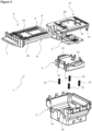
Figure 1 - is the general view of an air analysis device. -
Figure 2 - is the cross-sectional view of the air analysis device. -
Figure 3 - the exploded view of the air analysis device. -
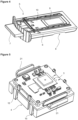
Figure 4 - is the perspective view of a cartridge. -
Figure 5 - is the perspective view of a camera and a camera holder. -
Figure 6 - is the perspective view of the body, and the camera and the camera holder placed into the body. -
Figure 7 - is the front view of the body, and the camera and the camera holder placed into the body. -
Figure 8 - is the cross-sectional view of the body, and the camera and the camera holder placed into the body while the cartridge is placed. -
Figure 9 - is the cross-sectional view of the body, and the camera and the camera holder placed into the body, when the cartridge is in place. -
Figure 10 - is the sideways view of the cartridge and the camera holder in the initial position. -
Figure 11 - is the sideways view of the cartridge and the camera holder after passing the initial position. -
Figure 12 - is the sideways view of the cartridge and the camera holder before the reaching the final position. -
Figure 13 - is the sideways view of the cartridge and the camera holder in the final position. -
Figure 14 - is the sideways view of the cartridge and the camera holder when locked in the final position. - The elements illustrated in the figures are numbered as follows.
- 1. Air analysis device
- 2. Body
- 3. Camera
- 4. Camera holder
- 5. Cartridge
- 6. Frame
- 7. Handle
- 8. Recess
- 9. Cover glass
- 10. Holder
- 11. Sliding member
- 12. Spring
- 13. Spring housing
- 14. First stopper
- 15. First claw
- 16. Second stopper
- 17. Second claw
- 18. Slide
- 19. Side wall
- 20. Window
- 21. Protrusion
- The air analysis device (1) comprises a body (2); at least one cover glass (9) whereon the sample is placed; a camera (3); a camera holder (4) which is positioned on the body (2) and whereon the camera (3) is fixed; at least one spring (12) which is disposed between the body (2) and the camera holder (4) and which pushes the camera holder (4) upwards in the vertical direction; a holder (10) whereon the cover glass (9) is fixed; a cartridge (5) whereon the holder (10) is placed; a sliding member (11) which is positioned on the body (2) so as to align with the camera (3) and which enables the cartridge (5) thereon to slidingly move horizontally; at least one recess (8) which is provided in the side wall of the cartridge (5); and a protrusion (21) which extends perpendicularly from the camera holder (4) to extend vertically and which is fitted into the recess (8) so as to enable the cartridge (5) to be centered on the camera (3) (
Figure 1 ,Figure 2 andFigure 3 ). - The cartridge (5) comprises a frame (6); a holder (10) which is placed on the frame (6) and whereon the cover glass (9) is fixed; and a handle (7) which is provided in front of the frame (6) and which enables the user to slide the cartridge (5) back and forth on the sliding member (11). The cartridge (5) further comprises a slide (18) which is provided on the side wall and which enables the cartridge to slidably move on the body (2). The particles in the air to be analyzed by the air analysis device (1) adhere to the cover glass (9), preferably to the gel on the cover glass (9). The user fixes the cover glass (9) on the frame (6) together with the holder (10) and pushes and slides the cartridge (5) onto the body (2) by means of the handle (7) (
Figure 4 ). - The sliding member (11) comprises a base, side walls (19) in the form of rails on both sides of the base, and a window (20) on the base. When the sliding member (11) is fixed on the body (2), the window (20) is positioned between the cover glass (9) and the camera (3). The cartridge (5) is attached on the sliding member (11), and hence on the body (2), so as to move back and forth in a horizontal plane as the slide (18) is fitted in the side walls (19). While the user inserts and removes the cartridge (5) from the air analysis device (1), the slides (18) on the cartridge (5) move in the side wall (19).
- In the embodiment of the present invention, the air analysis device (1) comprises four springs (12) which are squeezed between the camera holder (4) and the body (2), and spring housings (13) where the springs (12) are placed in the body (2). Said springs (12) apply upward force on the vertical axis to the camera holder (4) attached on the body (2) and pushes the camera holder (4) towards the sliding member (11) (
Figure 5 ,Figure 6 and Figure 7 ). - In an embodiment of the present invention, the air analysis device (1) comprises at least one first stopper (14) which is provided on the body (2) and which limits the final position that the camera holder (4) can reach in the body (2), and at least one first claw (15) which extends downward from the camera holder (4) and which prevents the camera holder (4) from moving further in the vertical axis upon contacting the first stopper (14). The upward force in the vertical axis applied by the springs (12) to the camera holder (4) is countered as the first claw (15) bears against the first stopper (14), and the upward movement of the camera holder (4) in the vertical axis on the body (2) is limited (
Figure 8 and Figure 9 ). - In another embodiment of the present invention, the air analysis device (1) comprises at least one second claw (17) which extends downwards from the sliding member (11) and which enables the sliding member (11) to be placed and fixed on the body (2) such that the camera (3) and camera holder (4) remain therebelow, and at least one second stopper (16) which is provided on the side wall of the body (2).
- In the embodiment of the present invention, the camera holder (4) is attached on the body (2) so as to be positioned on the springs (12). Meanwhile, the first claws (15) bear against the first stopper (14). Then, the sliding member (11) is fixed on the body (2) so as to be positioned above the camera (3) and the camera holder (4). While the user inserts the cartridge (5) into the air analysis device (1), the cartridge (5) slides on the sliding member (11) and moves in the horizontal plane by means the slides (18) entering the side wall (19) of the sliding member (11) (
Figure 10 ). During this movement of the cartridge (5), the rear wall of the cartridge (5) contacts the protrusion (21), and when the force applied to the protrusion (21) overcomes the force of the springs (12), the rear wall, together with the protrusion (21), pushes the camera holder (4) downwards in the vertical plane towards the base of the body (2) (Figure 11 ). Meanwhile, the springs (12) which support the camera holder (4) are compressed. This movement continues until the protrusion (21) on the camera holder (4) is fitted into the recess (8) on the side wall of the cartridge (5). When the protrusion (21) reaches the recess (8), the camera holder (4) starts to move upwards by means of the force of the spring (12) (Figure 12 andFigure 13 ). When the protrusion (21) is completely fitted into the recess (8), the movement of the cartridge (5) along the sliding member (11) and the upward movement of the camera holder (4) in the vertical plane end. In this case, the cover glass (9), the window (20) and the camera (3) align with each other, and the camera (3) is brought to the position where the air analysis device (1) can make the most accurate analysis. - By means of the present invention, the cover glass (9) is enabled to be placed correctly in the air analysis device (1) without requiring the user to make any additional intervention to the camera (3). Moreover, since the distance between the cover glass (9) and the camera (3) is enabled to be constant during all analysis processes, the air analysis device (1) is enabled to make accurate measurements and thus unnecessary use of the cover glass (9) is prevented. Furthermore, the camera (3) is enabled to remain clean while the cover glass (9) is inserted into and removed from the air analysis device (1).
Claims (9)
- An air analysis device (1) comprising a body (2); at least one cover glass (9) whereon the sample is placed; a camera (3); and a camera holder (4) which is positioned on the body (2) and whereon the camera (3) is fixed, characterized by at least one spring (12) which is disposed between the body (2) and the camera holder (4) and which pushes the camera holder (4) upwards in the vertical direction; a holder (10) whereon the cover glass (9) is fixed; a cartridge (5) whereon the holder (10) is placed; a sliding member (11) which is positioned on the body (2) so as to align with the camera (3) and which enables the cartridge (5) thereon to slidingly move horizontally; at least one recess (8) which is provided in the side wall of the cartridge (5); and a protrusion (21) which extends perpendicularly from the camera holder (4) to extend vertically and which is fitted into the recess (8) so as to enable the cartridge (5) to be centered on the camera (3).
- An air analysis device (1) as in Claim 1, characterized by the cartridge (5) comprising a frame (6); a holder (10) which is placed on the frame (6) and whereon the cover glass (9) is fixed; and a handle (7) which is provided in front of the frame (6) and which enables the user to slide the cartridge (5) back and forth on the sliding member (11).
- An air analysis device (1) as in Claim 2, characterized by the cartridge (5) comprising a slide (18) which is provided on the side wall and which enables the cartridge to slidably move on the body (2).
- An air analysis device (1) as in Claim 1, characterized by the sliding member (11) comprising a base, side walls (19) in the form of rails on both sides of the base, and a window (20) on the base.
- An air analysis device (1) as in Claim 4, characterized by the window (20) which is positioned between the cover glass (9) and the camera (3) when the sliding member (11) is fixed on the body (2).
- An air analysis device (1) as in Claim 1, characterized by four springs (12) which are squeezed between the camera holder (4) and the body (2), and spring housings (13) where the springs (12) are placed in the body (2).
- An air analysis device (1) as in Claim 6, characterized by the spring (12) which apply upward force on the vertical axis to the camera holder (4) attached on the body (2) and pushes the camera holder (4) towards the sliding member (11).
- An air analysis device (1) as in Claim 1, characterized by at least one first stopper (14) which is provided on the body (2) and which limits the final position that the camera holder (4) can reach in the body (2), and at least one first claw (15) which extends downward from the camera holder (4) and which prevents the camera holder (4) from moving further in the vertical axis upon contacting the first stopper (14).
- An air analysis device (1) as in Claim 1, characterized by at least one second claw (17) which extends downwards from the sliding member (11) and which enables the sliding member (11) to be placed and fixed on the body (2) such that the camera (3) and camera holder (4) remain therebelow, and at least one second stopper (16) which is provided on the side wall of the body (2).
Applications Claiming Priority (1)
| Application Number | Priority Date | Filing Date | Title |
|---|---|---|---|
| TR202221715 | 2022-12-30 |
Publications (2)
| Publication Number | Publication Date |
|---|---|
| EP4394376A1 true EP4394376A1 (en) | 2024-07-03 |
| EP4394376B1 EP4394376B1 (en) | 2026-06-10 |
Family
ID=89378586
Family Applications (1)
| Application Number | Title | Priority Date | Filing Date |
|---|---|---|---|
| EP23220166.5A Active EP4394376B1 (en) | 2022-12-30 | 2023-12-22 | An air analysis device |
Country Status (1)
| Country | Link |
|---|---|
| EP (1) | EP4394376B1 (en) |
Citations (7)
| Publication number | Priority date | Publication date | Assignee | Title |
|---|---|---|---|---|
| WO2011049965A1 (en) * | 2009-10-20 | 2011-04-28 | The Regents Of The University Of California | Incoherent lensfree cell holography and microscopy on a chip |
| WO2013070287A1 (en) | 2011-11-07 | 2013-05-16 | The Regents Of The University Of California | Maskless imaging of dense samples using multi-height lensfree microscope |
| WO2016064934A1 (en) * | 2014-10-25 | 2016-04-28 | Isle Management Co. | Air quality analyzing apparatus and method of analyzing air quality |
| WO2018165590A1 (en) | 2017-03-10 | 2018-09-13 | The Regents Of The University Of California | Mobile microscopy system for air quality monitoring |
| US20190293539A1 (en) * | 2015-03-06 | 2019-09-26 | Scanit Technologies, Inc. | Airborne particle monitor |
| US20210223155A1 (en) * | 2020-01-21 | 2021-07-22 | Honeywell International Inc. | Fluid composition sensor device and method of using the same |
| US20220348861A1 (en) * | 2019-11-14 | 2022-11-03 | Charm Sciences, Inc. | Universal test device, assembly, and method |
-
2023
- 2023-12-22 EP EP23220166.5A patent/EP4394376B1/en active Active
Patent Citations (7)
| Publication number | Priority date | Publication date | Assignee | Title |
|---|---|---|---|---|
| WO2011049965A1 (en) * | 2009-10-20 | 2011-04-28 | The Regents Of The University Of California | Incoherent lensfree cell holography and microscopy on a chip |
| WO2013070287A1 (en) | 2011-11-07 | 2013-05-16 | The Regents Of The University Of California | Maskless imaging of dense samples using multi-height lensfree microscope |
| WO2016064934A1 (en) * | 2014-10-25 | 2016-04-28 | Isle Management Co. | Air quality analyzing apparatus and method of analyzing air quality |
| US20190293539A1 (en) * | 2015-03-06 | 2019-09-26 | Scanit Technologies, Inc. | Airborne particle monitor |
| WO2018165590A1 (en) | 2017-03-10 | 2018-09-13 | The Regents Of The University Of California | Mobile microscopy system for air quality monitoring |
| US20220348861A1 (en) * | 2019-11-14 | 2022-11-03 | Charm Sciences, Inc. | Universal test device, assembly, and method |
| US20210223155A1 (en) * | 2020-01-21 | 2021-07-22 | Honeywell International Inc. | Fluid composition sensor device and method of using the same |
Also Published As
| Publication number | Publication date |
|---|---|
| EP4394376B1 (en) | 2026-06-10 |
Similar Documents
| Publication | Publication Date | Title |
|---|---|---|
| CN110044888B (en) | Portable immunity analyzer | |
| KR101514796B1 (en) | Image Sensor Module Mocket and Test Method of the Same | |
| CN107677843B (en) | Reagent container closures | |
| EP2264450B1 (en) | Holding device for medical test strip | |
| CN111947820B (en) | Device and method for testing torque of streaming media rearview mirror | |
| CN113660000A (en) | Tray | |
| CN110064931B (en) | Tension spring type microswitch assembling clamp | |
| CN215525834U (en) | Warehouse-in and warehouse-out mechanism and detection instrument | |
| CN112240824A (en) | Testing device | |
| CN114952704A (en) | Positioning mechanism and coil assembling device | |
| CN206300574U (en) | Lifter cubing | |
| CN220155941U (en) | Memory bank plug-pull device | |
| TR2022021715A2 (en) | AN AIR ANALYZER | |
| CN111665650B (en) | LCD panel testing device and method | |
| CN114958580B (en) | A hot lid structure for full-automatic nucleic acid analytic system | |
| CN109587377B (en) | Camera module inspection device with automatic socket and method for opening and closing socket | |
| CN117754253A (en) | Memory bank plugging device and use method thereof | |
| CN216160686U (en) | Data line joint detects smart location carrier | |
| CN214953354U (en) | Rapid detection card | |
| CN112362428B (en) | A sedimentation device and tablet making machine | |
| CN116913855A (en) | A chip bonding device and its fixing component | |
| CN115406351A (en) | A method and device for detecting earphone assembly accuracy | |
| CN113109144B (en) | A universal tool for testing the insertion and extraction force and sealing force of sealing strips | |
| CN117637516B (en) | A test structure of through silicon via | |
| CN219777708U (en) | Emergency sampling structure and analyzer |
Legal Events
| Date | Code | Title | Description |
|---|---|---|---|
| PUAI | Public reference made under article 153(3) epc to a published international application that has entered the european phase |
Free format text: ORIGINAL CODE: 0009012 |
|
| STAA | Information on the status of an ep patent application or granted ep patent |
Free format text: STATUS: REQUEST FOR EXAMINATION WAS MADE |
|
| 17P | Request for examination filed |
Effective date: 20231222 |
|
| AK | Designated contracting states |
Kind code of ref document: A1 Designated state(s): AL AT BE BG CH CY CZ DE DK EE ES FI FR GB GR HR HU IE IS IT LI LT LU LV MC ME MK MT NL NO PL PT RO RS SE SI SK SM TR |
|
| GRAP | Despatch of communication of intention to grant a patent |
Free format text: ORIGINAL CODE: EPIDOSNIGR1 |
|
| STAA | Information on the status of an ep patent application or granted ep patent |
Free format text: STATUS: GRANT OF PATENT IS INTENDED |
|
| GRAS | Grant fee paid |
Free format text: ORIGINAL CODE: EPIDOSNIGR3 |
|
| GRAA | (expected) grant |
Free format text: ORIGINAL CODE: 0009210 |
|
| STAA | Information on the status of an ep patent application or granted ep patent |
Free format text: STATUS: THE PATENT HAS BEEN GRANTED |
|
| INTG | Intention to grant announced |
Effective date: 20260421 |
|
| AK | Designated contracting states |
Kind code of ref document: B1 Designated state(s): AL AT BE BG CH CY CZ DE DK EE ES FI FR GB GR HR HU IE IS IT LI LT LU LV MC ME MK MT NL NO PL PT RO RS SE SI SK SM TR |
|
| REG | Reference to a national code |
Ref country code: CH Ref legal event code: F10 Free format text: ST27 STATUS EVENT CODE: U-0-0-F10-F00 (AS PROVIDED BY THE NATIONAL OFFICE) Effective date: 20260610 Ref country code: GB Ref legal event code: FG4D |
|
| REG | Reference to a national code |
Ref country code: IE Ref legal event code: FG4D |
|
| REG | Reference to a national code |
Ref country code: DE Ref legal event code: R096 Ref document number: 602023018307 Country of ref document: DE |