EP4394311A1 - Method for structured illumination microscopy and structured illumination microscope - Google Patents
Method for structured illumination microscopy and structured illumination microscope Download PDFInfo
- Publication number
- EP4394311A1 EP4394311A1 EP22216686.0A EP22216686A EP4394311A1 EP 4394311 A1 EP4394311 A1 EP 4394311A1 EP 22216686 A EP22216686 A EP 22216686A EP 4394311 A1 EP4394311 A1 EP 4394311A1
- Authority
- EP
- European Patent Office
- Prior art keywords
- test surface
- phase
- pattern
- determining
- light beam
- Prior art date
- Legal status (The legal status is an assumption and is not a legal conclusion. Google has not performed a legal analysis and makes no representation as to the accuracy of the status listed.)
- Pending
Links
- 238000005286 illumination Methods 0.000 title claims abstract description 28
- 238000000034 method Methods 0.000 title claims abstract description 19
- 238000000386 microscopy Methods 0.000 title abstract description 6
- 230000003287 optical effect Effects 0.000 claims abstract description 32
- 230000000737 periodic effect Effects 0.000 claims description 90
- 238000005259 measurement Methods 0.000 claims description 84
- 230000010363 phase shift Effects 0.000 claims description 15
- 230000009466 transformation Effects 0.000 claims description 11
- 230000001131 transforming effect Effects 0.000 claims description 4
- 230000001419 dependent effect Effects 0.000 description 1
- 230000000694 effects Effects 0.000 description 1
Images

Classifications
-
- G—PHYSICS
- G01—MEASURING; TESTING
- G01B—MEASURING LENGTH, THICKNESS OR SIMILAR LINEAR DIMENSIONS; MEASURING ANGLES; MEASURING AREAS; MEASURING IRREGULARITIES OF SURFACES OR CONTOURS
- G01B11/00—Measuring arrangements characterised by the use of optical techniques
- G01B11/24—Measuring arrangements characterised by the use of optical techniques for measuring contours or curvatures
- G01B11/25—Measuring arrangements characterised by the use of optical techniques for measuring contours or curvatures by projecting a pattern, e.g. one or more lines, moiré fringes on the object
- G01B11/2518—Projection by scanning of the object
- G01B11/2527—Projection by scanning of the object with phase change by in-plane movement of the patern
-
- G—PHYSICS
- G02—OPTICS
- G02B—OPTICAL ELEMENTS, SYSTEMS OR APPARATUS
- G02B21/00—Microscopes
- G02B21/06—Means for illuminating specimens
-
- G—PHYSICS
- G02—OPTICS
- G02B—OPTICAL ELEMENTS, SYSTEMS OR APPARATUS
- G02B21/00—Microscopes
- G02B21/0004—Microscopes specially adapted for specific applications
- G02B21/002—Scanning microscopes
- G02B21/0024—Confocal scanning microscopes (CSOMs) or confocal "macroscopes"; Accessories which are not restricted to use with CSOMs, e.g. sample holders
- G02B21/0032—Optical details of illumination, e.g. light-sources, pinholes, beam splitters, slits, fibers
-
- G—PHYSICS
- G01—MEASURING; TESTING
- G01B—MEASURING LENGTH, THICKNESS OR SIMILAR LINEAR DIMENSIONS; MEASURING ANGLES; MEASURING AREAS; MEASURING IRREGULARITIES OF SURFACES OR CONTOURS
- G01B11/00—Measuring arrangements characterised by the use of optical techniques
- G01B11/02—Measuring arrangements characterised by the use of optical techniques for measuring length, width or thickness
- G01B11/06—Measuring arrangements characterised by the use of optical techniques for measuring length, width or thickness for measuring thickness ; e.g. of sheet material
- G01B11/0608—Height gauges
-
- G—PHYSICS
- G01—MEASURING; TESTING
- G01B—MEASURING LENGTH, THICKNESS OR SIMILAR LINEAR DIMENSIONS; MEASURING ANGLES; MEASURING AREAS; MEASURING IRREGULARITIES OF SURFACES OR CONTOURS
- G01B11/00—Measuring arrangements characterised by the use of optical techniques
- G01B11/24—Measuring arrangements characterised by the use of optical techniques for measuring contours or curvatures
- G01B11/25—Measuring arrangements characterised by the use of optical techniques for measuring contours or curvatures by projecting a pattern, e.g. one or more lines, moiré fringes on the object
-
- G—PHYSICS
- G01—MEASURING; TESTING
- G01B—MEASURING LENGTH, THICKNESS OR SIMILAR LINEAR DIMENSIONS; MEASURING ANGLES; MEASURING AREAS; MEASURING IRREGULARITIES OF SURFACES OR CONTOURS
- G01B11/00—Measuring arrangements characterised by the use of optical techniques
- G01B11/24—Measuring arrangements characterised by the use of optical techniques for measuring contours or curvatures
- G01B11/25—Measuring arrangements characterised by the use of optical techniques for measuring contours or curvatures by projecting a pattern, e.g. one or more lines, moiré fringes on the object
- G01B11/2518—Projection by scanning of the object
- G01B11/2522—Projection by scanning of the object the position of the object changing and being recorded
-
- G—PHYSICS
- G01—MEASURING; TESTING
- G01B—MEASURING LENGTH, THICKNESS OR SIMILAR LINEAR DIMENSIONS; MEASURING ANGLES; MEASURING AREAS; MEASURING IRREGULARITIES OF SURFACES OR CONTOURS
- G01B9/00—Measuring instruments characterised by the use of optical techniques
- G01B9/04—Measuring microscopes
-
- G—PHYSICS
- G02—OPTICS
- G02B—OPTICAL ELEMENTS, SYSTEMS OR APPARATUS
- G02B21/00—Microscopes
- G02B21/0004—Microscopes specially adapted for specific applications
- G02B21/0016—Technical microscopes, e.g. for inspection or measuring in industrial production processes
-
- G—PHYSICS
- G02—OPTICS
- G02B—OPTICAL ELEMENTS, SYSTEMS OR APPARATUS
- G02B21/00—Microscopes
- G02B21/0004—Microscopes specially adapted for specific applications
- G02B21/002—Scanning microscopes
-
- G—PHYSICS
- G02—OPTICS
- G02B—OPTICAL ELEMENTS, SYSTEMS OR APPARATUS
- G02B21/00—Microscopes
- G02B21/0004—Microscopes specially adapted for specific applications
- G02B21/002—Scanning microscopes
- G02B21/0024—Confocal scanning microscopes (CSOMs) or confocal "macroscopes"; Accessories which are not restricted to use with CSOMs, e.g. sample holders
- G02B21/0052—Optical details of the image generation
- G02B21/0072—Optical details of the image generation details concerning resolution or correction, including general design of CSOM objectives
-
- G—PHYSICS
- G02—OPTICS
- G02B—OPTICAL ELEMENTS, SYSTEMS OR APPARATUS
- G02B21/00—Microscopes
- G02B21/0004—Microscopes specially adapted for specific applications
- G02B21/002—Scanning microscopes
- G02B21/0024—Confocal scanning microscopes (CSOMs) or confocal "macroscopes"; Accessories which are not restricted to use with CSOMs, e.g. sample holders
- G02B21/0052—Optical details of the image generation
- G02B21/0076—Optical details of the image generation arrangements using fluorescence or luminescence
-
- G—PHYSICS
- G02—OPTICS
- G02B—OPTICAL ELEMENTS, SYSTEMS OR APPARATUS
- G02B21/00—Microscopes
- G02B21/0004—Microscopes specially adapted for specific applications
- G02B21/002—Scanning microscopes
- G02B21/0024—Confocal scanning microscopes (CSOMs) or confocal "macroscopes"; Accessories which are not restricted to use with CSOMs, e.g. sample holders
- G02B21/008—Details of detection or image processing, including general computer control
-
- G—PHYSICS
- G02—OPTICS
- G02B—OPTICAL ELEMENTS, SYSTEMS OR APPARATUS
- G02B21/00—Microscopes
- G02B21/36—Microscopes arranged for photographic purposes or projection purposes or digital imaging or video purposes including associated control and data processing arrangements
- G02B21/365—Control or image processing arrangements for digital or video microscopes
- G02B21/367—Control or image processing arrangements for digital or video microscopes providing an output produced by processing a plurality of individual source images, e.g. image tiling, montage, composite images, depth sectioning, image comparison
Definitions
- the current invention relates to a method of structured illumination microscopy for determining a height map of a test surface wherein use is made of a structured illumination microscope.
- the invention is further related to a structured illumination microscope for determining a height map of a test surface.
- a light beam is modulated to form a pattern which is projected onto the test surface.
- the light beam may be modulated by a spatial light modulator.
- the pattern may be phase shifted in a direction perpendicular to the light beam according to the phase of the pattern to allow for determining the height of the test surface.
- a downside of the known methods is that errors may be introduced in determining the height map due to multiple measurements having to be performed.
- the aim of the invention is to reduce errors in methods of structured illumination microscopy for determining a height map.
- the test surface may be any test surface suitable for determining a height map thereof.
- the test surface may be a curved test surface such as a lens.
- the test surface may also be tilted relative to a scanning direction of the microscope.
- the test surface may be opaque or transparent.
- a structured illumination microscope comprising a light source for emitting a light beam.
- the light source may be a laser beam, e.g. emitting light of a specific frequency.
- the light source may also be a white light source, emitting light of many frequencies, e.g. emitting white light.
- the emitted light beam follows a light path from the light source to the test surface where it is reflected towards an optical detector.
- the microscope further comprises a test surface holder for holding a test surface of which a height map is to be determined.
- the test surface holder may hold the test surface perpendicular to a light path of the light beam or tilted relative to the light path.
- the microscope further comprises an optical detector for detecting a reflected light beam.
- the reflected light beam is reflected by the test surface provided in the test surface holder.
- the optical detector may be a camera adapted for measuring the reflected light beam.
- the reflected light beam may be directed towards the optical detector using optical means for directing the light beam, such as lenses.
- the microscope further comprises a processor connected to the spatial light modulator, for operating the spatial light modulator, to the scanning means, for operating the scanning means, and to the optical detector, for operating the optical detector and receiving a measured signal of the optical detector.
- the method comprises providing the test surface in the test surface holder of the structured illumination microscope for determining the height map of the test surface.
- the method further comprises emitting a light beam from the light source and modulating the emitted light beam with the spatial light modulator.
- the emitted light beam is modulated to generate a measurement pattern which is periodic in a direction perpendicular to the light beam and which measurement pattern has a measurement phase.
- the measurement phase is related to the amount of phase shifts of the pattern required to complete a full cycle of the pattern such that the pattern is the same as before performing the phase shifts.
- the pattern is periodic in a direction perpendicular to the light beam.
- the pattern may be a periodic sinusoidal pattern having straight darker and lighter lines. This pattern is periodic in a direction perpendicular to the straight darker and lighter lines, but not in a direction parallel to these lines.
- the reflected light beam is detected with the optical detector for each scanning position and each phase shift, which results in a detected signal, e.g. in each pixel of the optical detector.
- the detected signal is then send to the processor for determining the height map of the test surface.
- the height map is determined by determining a height of the test surface, e.g. for each pixel of the optical detector, based on the detected signal. For example, the height map may be determined based on determining an amplitude of the detected signal at a corresponding signal and determining a scanning position of the scanning means for which the amplitude is maximal.
- the scanning position for which the amplitude is maximal is then related to the height of the test surface at the respective pixel.
- the light beam is modulated such that the measurement pattern is a superposition of at least a first periodic pattern having a first phase and a second periodic pattern having a second phase.
- the first phase and the second phase are different from each other.
- the measurement pattern phase is an integer multiple of the least common multiple of the first phase and the second phase.
- the first phase may be a 3 phase and the second phase may be a 4 phase in which case the measurement pattern phase is a 12 phase requiring 12 phase shifts to complete a full cycle.
- the measurement pattern is a superposition of at least two different patterns and the measurement pattern is shifted according to the phase shifts of the superposed patterns.
- the resulting measurement pattern may have improved characteristics for determining a height map of the test surface compared to a randomly chosen measurement pattern.
- the measurement pattern may be a superposition of a first periodic pattern having a large fringe width and a second periodic pattern having a small fringe width to allow for simultaneous measurement of areas of a test surface having higher slopes and lower slopes.
Landscapes
- Physics & Mathematics (AREA)
- General Physics & Mathematics (AREA)
- Chemical & Material Sciences (AREA)
- Analytical Chemistry (AREA)
- Optics & Photonics (AREA)
- Engineering & Computer Science (AREA)
- Computer Vision & Pattern Recognition (AREA)
- Multimedia (AREA)
- General Engineering & Computer Science (AREA)
- Microscoopes, Condenser (AREA)
- Length Measuring Devices By Optical Means (AREA)
- Investigating, Analyzing Materials By Fluorescence Or Luminescence (AREA)
Abstract
The current invention relates to a method of structured illumination microscopy for determining a height map of a test surface wherein use is made of a structured illumination microscope. The invention is further related to a structured illumination microscope for determining a height map of a test surface. The microscope comprises a light source, a spatial light modulator, scanning means, an optical detector, and a processor.

Description
- The current invention relates to a method of structured illumination microscopy for determining a height map of a test surface wherein use is made of a structured illumination microscope. The invention is further related to a structured illumination microscope for determining a height map of a test surface.
- In known methods of structured illumination microscopy for determining a height map of a test surface a light beam is modulated to form a pattern which is projected onto the test surface. The light beam may be modulated by a spatial light modulator. During measurement, the pattern may be phase shifted in a direction perpendicular to the light beam according to the phase of the pattern to allow for determining the height of the test surface.
- The kind of pattern to be used, for example fringe patterns, grid patterns, or fractal patterns, is dependent on the test surface, e.g. a flat test surface, or a curved test surface, such as a lens, and the specific instrument setup used, which dependency has an effect on the results. For example, a measurement pattern with small features may result in a high scanning-axis resolution, while a measurement pattern with large features may result in a low scanning-axis resolution.
- Since the measurement with the structured illumination microscope may depend on the measurement pattern that is used, multiple measurements may be required to determine a height map of a test surface. For example, for a sloped test surface, such as a lens, multiple measurements may be required because areas with higher slope may be best measured with measurement patterns having a larger fringe width, whereas areas with a lower slope may be best measured with measurement patterns having a smaller fringe width. In another example, the test surface is tilted and patterns having periodicities along a direction of the tilt and perpendicular to the direction of the tilt may be required to determine the height map of the titled test surface.
- A downside of the known methods is that errors may be introduced in determining the height map due to multiple measurements having to be performed.
- The aim of the invention is to reduce errors in methods of structured illumination microscopy for determining a height map.
- The aim of the invention is achieved by the method of
claim 1. - The test surface may be any test surface suitable for determining a height map thereof. For example, the test surface may be a curved test surface such as a lens. The test surface may also be tilted relative to a scanning direction of the microscope. The test surface may be opaque or transparent.
- Use is made of a structured illumination microscope comprising a light source for emitting a light beam. For example, the light source may be a laser beam, e.g. emitting light of a specific frequency. The light source may also be a white light source, emitting light of many frequencies, e.g. emitting white light. The emitted light beam follows a light path from the light source to the test surface where it is reflected towards an optical detector.
- The microscope further comprises a spatial light modulator for modulating the light beam emitted by the light source. The spatial light modulator may allow for many different modulations of the light beam, such as modulations resulting in different fringe patterns, different grid patterns, or different fractal patterns. The spatial light modulator may be configured to dynamically change the modulation of the light beam.
- The microscope further comprises a test surface holder for holding a test surface of which a height map is to be determined. The test surface holder may hold the test surface perpendicular to a light path of the light beam or tilted relative to the light path.
- Scanning means are provided to direct the modulated light beam to the test surface in the test surface holder. The scanning means may comprise optical means for directing the light beam, such as lenses. The scanning means and the test surface holder are moveable relative to each other between different scanning positions in a direction parallel to the light beam. For example, in an embodiment the test surface is perpendicular to the light beam and the scanning means are moved between different heights above the test surface in a direction perpendicular to the test surface. This allows for measuring reflected light from the test surface at different positions above the test surface in the test surface holder.
- The microscope further comprises an optical detector for detecting a reflected light beam. The reflected light beam is reflected by the test surface provided in the test surface holder. The optical detector may be a camera adapted for measuring the reflected light beam. The reflected light beam may be directed towards the optical detector using optical means for directing the light beam, such as lenses.
- The microscope further comprises a processor connected to the spatial light modulator, for operating the spatial light modulator, to the scanning means, for operating the scanning means, and to the optical detector, for operating the optical detector and receiving a measured signal of the optical detector.
- The method comprises providing the test surface in the test surface holder of the structured illumination microscope for determining the height map of the test surface. The method further comprises emitting a light beam from the light source and modulating the emitted light beam with the spatial light modulator. The emitted light beam is modulated to generate a measurement pattern which is periodic in a direction perpendicular to the light beam and which measurement pattern has a measurement phase. The measurement phase is related to the amount of phase shifts of the pattern required to complete a full cycle of the pattern such that the pattern is the same as before performing the phase shifts.
- As discussed above many different patterns may be obtained. The pattern is periodic in a direction perpendicular to the light beam. For example, the pattern may be a periodic sinusoidal pattern having straight darker and lighter lines. This pattern is periodic in a direction perpendicular to the straight darker and lighter lines, but not in a direction parallel to these lines.
- The method further comprises moving the scanning means between the different scanning positions and modulating the light beam with the spatial light modulator such that the measurement pattern is phase shifted in the direction perpendicular to the light beam according to the measurement phase. Thus, during performing the method and measuring the reflected light beam, the measurement pattern is phase shifted such that measurements are performed for different shifts of the pattern and, additionally, for different scanning positions of the scanning means. The measurement pattern is phase shifted according to the measurement pattern phase. For example, if the measurement pattern has a measurement pattern phase of n phases than the measurement pattern may be shifted n times during measurement to return the pattern to its original position.
- The reflected light beam is detected with the optical detector for each scanning position and each phase shift, which results in a detected signal, e.g. in each pixel of the optical detector. The detected signal is then send to the processor for determining the height map of the test surface. The height map is determined by determining a height of the test surface, e.g. for each pixel of the optical detector, based on the detected signal. For example, the height map may be determined based on determining an amplitude of the detected signal at a corresponding signal and determining a scanning position of the scanning means for which the amplitude is maximal. The scanning position for which the amplitude is maximal is then related to the height of the test surface at the respective pixel.
- The light beam is modulated such that the measurement pattern is a superposition of at least a first periodic pattern having a first phase and a second periodic pattern having a second phase. The first phase and the second phase are different from each other. The measurement pattern phase is an integer multiple of the least common multiple of the first phase and the second phase. For example, the first phase may be a 3 phase and the second phase may be a 4 phase in which case the measurement pattern phase is a 12 phase requiring 12 phase shifts to complete a full cycle.
- Thus, the measurement pattern is a superposition of at least two different patterns and the measurement pattern is shifted according to the phase shifts of the superposed patterns. By appropriately choosing the first periodic pattern and the second periodic pattern the resulting measurement pattern may have improved characteristics for determining a height map of the test surface compared to a randomly chosen measurement pattern. For example, the measurement pattern may be a superposition of a first periodic pattern having a large fringe width and a second periodic pattern having a small fringe width to allow for simultaneous measurement of areas of a test surface having higher slopes and lower slopes. Thus, a single measurement cycle is needed to measure the test surface and errors resulting from performing multiple measurement cycles with multiple measurement patterns are reduced.
- In embodiments, the determining of the height map further comprises, for each pixel of the optical detector:
- performing a Fourier transformation on the detected signal transforming the detected signal to frequency space;
- separating the detected signal into a first presignal related to the first periodic pattern and a second presignal related to the second periodic pattern;
- performing an inverse Fourier transformation on each of the first presignal and the second presignal;
- determining a first premap by determining a height of the test surface based on the first presignal, e.g. by determining a first amplitude of the first signal at each pixel and determining a scanning position wherein the first amplitude is maximal;
- determining a second premap by determining a height of the test surface based on the second presignal, e.g. by determining a second amplitude of the second presignal at each pixel and determining a scanning position wherein the second amplitude is maximal; and
- determining the height map based on the first premap and the second premap.
- An advantage of using a measurement pattern that is a superposition of two periodic patterns having different phases is that the detected signal may be separated in frequency space in a first presignal arising from the periodic pattern having the first phase and a second presignal arising from the second pattern having the second phase. Thus by performing a Fourier transformation on the detected signal the detected signal may be separated into the first presignal, related to the first periodic pattern, and the second presignal, related to the second periodic pattern. An inverse Fourier transformation may then be performed independently on each of the first presignal and the second presignal to obtain a first presignal in coordinate space, related to the first periodic pattern, and a second presignal in coordinate space, related to the second periodic pattern. For each presignal a premap may be determined wherein using the first periodic pattern may result in a first premap having first characteristics and using the second periodic pattern may have result in a second premap having second characteristics. The height map is then determined based on the first premap and the second premap. The resulting height map may have advantageous characteristics of the first premap and the second premap.
- A potential downside of determining a height map using structured illumination microscopy is a longer throughput time, which may increase due to a larger amount of phase shifts required. In embodiments, the throughput time is reduced by taking, at each scanning position only a single image and wherein the measurement pattern is phase shifted with a single phase between scanning positions. The height map in these embodiments may be determined based on determining an amplitude of the detected signal at the corresponding pixel and determining a scanning position wherein the amplitude is maximal. The scanning position wherein the amplitude is maximal is the scanning position wherein the test surface is in focus of the microscope which allows to determine the height map.
- In embodiments, the measurement pattern, the first periodic pattern, and/or the second periodic pattern is a sinusoidal periodic pattern, a binary strip pattern, or a periodic circular pattern.
- In embodiments, the first periodic pattern has a larger fringe width and the second periodic pattern has a smaller fringe width.
- In embodiments, the first periodic pattern is periodic in a first direction parallel to the test surface and the second periodic pattern is periodic in a second direction parallel to the test surface, e.g. wherein the first direction is perpendicular to the second direction, and wherein phase shifting comprises phase shifting the measurement pattern in the first direction parallel to the test surface and in the second direction parallel to the test surface according to the respective phases.
- The invention further relates to a structured illumination microscope for determining a height map of a test surface comprising:
- a light source for emitting a light beam;
- a spatial light modulator for modulating the light beam emitted by the light source;
- a test surface holder for holding a test surface;
- scanning means to direct the modulated light beam to the test surface in the test surface holder, wherein the scanning means and the test surface holder are movable relative to each other between different scanning positions in a direction parallel to the light beam;
- an optical detector for detecting a reflected light beam reflected by a test surface provided in the test surface holder; and
- a processor connected to the spatial light modulator, the scanning means, and the optical detector,
- emit a light beam from the light source and modulate the light beam emitted by the light source with the spatial light modulator to generate a measurement pattern which is periodic in a direction perpendicular to the light beam and which measurement pattern has a measurement pattern phase;
- direct the modulated light beam to the test surface with the scanning means;
- move the scanning means between the different scanning positions and modulating the light beam with the spatial light modulator such that the measurement pattern is phase shifted in the direction perpendicular to the light beam according to the measurement pattern phase;
- detect the reflected light beam for each scanning position and each phase shift with the optical detector resulting in a detected signal in each pixel of the optical detector; and
- determine, by the processor, a height map of the test surface by determining a height of the test surface based on the detected signal, e.g. based on determining an amplitude of the detected signal at the corresponding pixel and determining a scanning position wherein the amplitude is maximal,
- In embodiments of the microscope, the processor is configured to, when determining the height map, for each pixel of the optical detector:
- perform a Fourier transformation on the detected signal transforming the detected signal to frequency space;
- separate the detected signal into a first presignal related to the first periodic pattern and a second presignal related to the second periodic pattern;
- perform an inverse Fourier transformation on each of the first presignal and the second presignal;
- determine a first premap by determining a height of the test surface based on the first presignal, e.g. by determining a first amplitude of the first signal at each pixel and determine a scanning position wherein the first amplitude is maximal;
- determining a second premap by determining a height of the test surface based on the presecond signal, e.g. by determining a second amplitude of the second signal at each pixel and determining a scanning position wherein the second amplitude is maximal; and
- determine the height map based on the first premap and the second premap.
- In embodiments of the microscope, the microscope is configured to take only a single image at each scanning position and wherein the microscope is configured to phase shift the measurement with a single phase between scanning positions.
- In embodiments of the microscope, the first periodic pattern, and/or the second periodic pattern is a sinusoidal periodic pattern, a binary strip pattern, or a periodic circular pattern.
- In embodiments of the microscope, the first periodic pattern has a larger fringe width and the second periodic pattern has a smaller fringe width.
- In embodiments of the microscope, the first periodic pattern is periodic in a first direction parallel to the test surface and the second periodic pattern is periodic in a second direction parallel to the test surface, e.g. wherein the first direction is perpendicular to the second direction, and wherein the structured illumination microscope is configured to phase shift the measurement pattern in the first direction parallel to the test surface and in the second direction parallel to the test surface according to the respective phases.
- The invention will now be explained with reference to the drawing, in which:
-
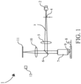
Fig. 1 shows a structured illumination microscope; -
Fig. 2 shows a first periodic pattern, a second periodic pattern, and a resulting superposed pattern; and -
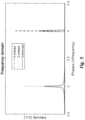
Fig. 3 shows a Fourier transformed detected signal. -
Figure 1 shows astructured illumination microscope 1 comprising a light source 2 for emitting alight beam 3. The structuredillumination microscope 1 is configured for determining a height map of thetest surface 8. - The
light beam 3 emitted by the light source 2 is modulated by the spatiallight modulator 4. The spatiallight modulator 4 is configured to modulate thelight beam 3 to generate a measurement pattern which is periodic in a direction perpendicular to thelight beam 3. The thus generated measurement pattern has a measurement pattern phase which is a superposition of at least a first periodic pattern having a first phase and a second periodic pattern having a second phase. For example, the first phase may be a 3 phase and the second phase may be a 4 phase, such that the measurement pattern has a 12 phase. - The light beam is directed by the lens 5 and the reflective element 6 towards the scanning means 7 which direct the
light beam 3 to thetest surface 8 in the test surface holder. Thetest surface 8 and the scanning means 7 are moveable relative to each other between different scanning positions in a direction parallel to thelight beam 3. The scanning means 7 may direct thelight beam 3 towards thetest surface 8 to testpoint 9 to measure the height thereof. - The
test surface 8 reflects thelight beam 3 via reflective means 6 andlens 10 towards theoptical detector 11 for detecting the reflectedlight beam 3. Theprocessor 12 is connected to theoptical detector 11, for determining the height map. - The
microscope 1 is configured to, when thetest surface 8 is provided in the test surface holder, comprises: - emit the
light beam 3 from the light source 2 and modulate thelight beam 3 emitted by the light source 2 with the spatiallight modulator 4 to generate a measurement pattern which is periodic in a direction perpendicular to thelight beam 3 and which measurement pattern has a measurement pattern phase; - direct the modulated
light beam 3 to thetest surface 8 with the scanning means 7; - move the scanning means 7 between the different scanning positions and modulating the
light beam 3 with the spatiallight modulator 4 such that the measurement pattern is phase shifted in the direction perpendicular to thelight beam 3 according to the measurement pattern phase; - detect the reflected
light beam 3 for each scanning position and each phase shift with theoptical detector 11 resulting in a detected signal in each pixel of theoptical detector 11; and - determine, by the
processor 12, a height map of thetest surface 8 by determining a height of thetest surface 8 based on the detected signal, e.g. based on determining an amplitude of the detected signal at the corresponding pixel and determining a scanning position wherein the amplitude is maximal. -
Figure 2 shows a firstperiodic pattern 21 having a three phase, a secondperiodic pattern 22 having a four phase, and a resulting superposedpattern 23 having a twelve phase. As can be seen from the figure the firstperiodic pattern 21 has to be shifted three times before a cycle is completed, i.e. after three phase shifts, the firstperiodic pattern 21 returns to the unshifted firstperiodic pattern 21. Similarly, the secondperiodic pattern 22 having the four phase has to be shifted four times before a cycle is completed. - The resulting superimposed
pattern 23 is a superposition of the threephase pattern 21 and the fourphase pattern 22 and has a resulting twelve phase. Thus the measurement pattern, which is the superimposed pattern, 23 has to be shifted twelve times before the cycle is completed. -
Figure 3 shows the separatable signal after Fourier transformation obtained from a measurement of themeasurement pattern 23, wherein the signal has a twelve phase.Figure 3 further shows a detected signal if only the threephase pattern 21 were used and a detected signal if only the fourphase pattern 22 were used. - As can be seen in
figure 3 , themeasurement pattern 23 contains information from both the firstperiodic pattern 21 and the secondperiodic pattern 22. Thus themeasurement pattern 23 may be used to determine a height map instead of using separately the threephase pattern 21 and the fourphase 22. Since the measurement does not have to be repeated for different patterns, errors resulting from performing multiple measurements may be reduced and the resulting height map may be more accurate. Other periodic patterns having other phases or characteristics, such as a repeated square pattern, a circular symmetric pattern, may equally be used in the method.
Claims (12)
- Method for determining a height map of a test surface wherein use is made of a structured illumination microscope comprising:- a light source for emitting a light beam;- a spatial light modulator for modulating the light beam emitted by the light source;- a test surface holder for holding a test surface;- scanning means to direct the modulated light beam to the test surface in the test surface holder, wherein the scanning means and the test surface holder are movable relative to each other between different scanning positions in a direction parallel to the light beam;- an optical detector for detecting a reflected light beam reflected by a test surface provided in the test surface holder; and- a processor connected to the optical detector,wherein the method comprises:- providing the test surface in the test surface holder of the structured illumination microscope;- emitting a light beam from the light source and modulating the light beam emitted by the light source with the spatial light modulator to generate a measurement pattern which is periodic in a direction perpendicular to the light beam and which measurement pattern has a measurement pattern phase;- directing the modulated light beam to the test surface with the scanning means;- moving the scanning means between the different scanning positions and modulating the light beam with the spatial light modulator such that the measurement pattern is phase shifted in the direction perpendicular to the light beam according to the measurement pattern phase;- detecting the reflected light beam for each scanning position and each phase shift with the optical detector resulting in a detected signal, e.g. in each pixel of the optical detector; and- determining a height map of the test surface, by the processor, by determining a height of the test surface based on the detected signal, e.g. based on determining an amplitude of the detected signal at the corresponding pixel and determining a scanning position wherein the amplitude is maximal,wherein the light beam is modulated such that the measurement pattern is a superposition of at least a first periodic pattern having a first phase and a second periodic pattern having a second phase, wherein the first phase and the second phase are different from each other, and wherein the measurement pattern phase is an integer multiple of the least common multiple of the first phase and the second phase.
- Method according to claim 1, wherein the determining of the height map further comprises, for each pixel of the optical detector:- performing a Fourier transformation on the detected signal transforming the detected signal to frequency space;- separating the detected signal into a first presignal related to the first periodic pattern and a second presignal related to the second periodic pattern;- performing an inverse Fourier transformation on each of the first presignal and the second presignal;- determining a first premap by determining a height of the test surface based on the first presignal, e.g. by determining a first amplitude of the first presignal at each pixel and determining a scanning position wherein the first amplitude is maximal;- determining a second premap by determining a height of the test surface based on the second presignal, e.g. by determining a second amplitude of the second signal at each pixel and determining a scanning position wherein the second amplitude is maximal; and- determining the height map based on the first map and the second map.
- Method according to one or more of the preceding claims, wherein at each scanning position only a single image is taken and wherein the measurement pattern is phase shifted with a single phase between scanning positions.
- Method according to one or more of the preceding claims, wherein the measurement pattern, the first periodic pattern, and/or the second periodic pattern is a sinusoidal periodic pattern, a binary strip pattern, or a periodic circular pattern.
- Method according to one or more of the preceding claims, wherein the first periodic pattern has a larger fringe width and the second periodic pattern has a smaller fringe width.
- Method according to one or more of the preceding claims, wherein the first periodic pattern is periodic in a first direction parallel to the test surface and the second periodic pattern is periodic in a second direction parallel to the test surface, e.g. wherein the first direction is perpendicular to the second direction, and wherein phase shifting comprises phase shifting the measurement pattern in the first direction parallel to the test surface and in the second direction parallel to the test surface according to the respective phases.
- Structured illumination microscope for determining a height map of a test surface comprising:- a light source for emitting a light beam;- a spatial light modulator for modulating the light beam emitted by the light source;- a test surface holder for holding a test surface;- scanning means to direct the modulated light beam to the test surface in the test surface holder, wherein the scanning means and the test surface holder are movable relative to each other between different scanning positions in a direction parallel to the light beam;- an optical detector for detecting a reflected light beam reflected by a test surface provided in the test surface holder; and- a processor connected to the spatial light modulator, the scanning means, and the optical detector,wherein the microscope is configured to, when the test surface is provided in the test surface holder, comprises:- emit a light beam from the light source and modulate the light beam emitted by the light source with the spatial light modulator to generate a measurement pattern which is periodic in a direction perpendicular to the light beam and which measurement pattern has a measurement pattern phase;- direct the modulated light beam to the test surface with the scanning means;- move the scanning means between the different scanning positions and modulating the light beam with the spatial light modulator such that the measurement pattern is phase shifted in the direction perpendicular to the light beam according to the measurement pattern phase;- detect the reflected light beam for each scanning position and each phase shift with the optical detector resulting in a detected signal; and- determine, by the processor, a height map of the test surface by determining a height of the test surface based on the detected signal, e.g. based on determining an amplitude of the detected signal at the corresponding pixel and determining a scanning position wherein the amplitude is maximal,wherein the light beam is modulated such that the measurement pattern is a superposition of at least a first periodic pattern having a first phase and a second periodic pattern having a second phase, wherein the first phase and the second phase are different from each other, and wherein the measurement pattern phase is an integer multiple of the least common multiple of the first phase and the second phase.
- Structured illumination microscope according to claim 7, wherein the processor is configured to, when determining the height map, for each pixel of the optical detector:- perform a Fourier transformation on the detected signal transforming the detected signal to frequency space;- separate the detected signal into a first presignal related to the first periodic pattern and a second presignal related to the second periodic pattern;- perform an inverse Fourier transformation on each of the first presignal and the second presignal;- determine a first premap by determining a height of the test surface based on the first presignal, e.g. by determining a first amplitude of the first signal at each pixel and determine a scanning position wherein the first amplitude is maximal;- determining a second premap by determining a height of the test surface based on the presecond signal, e.g. by determining a second amplitude of the second signal at each pixel and determining a scanning position wherein the second amplitude is maximal; and- determine the height map based on the first premap and the second premap.
- Structured illumination microscope according to one or more of claims 7-8, wherein the microscope is configured to take only a single image at each scanning position and wherein the microscope is configured to phase shift the measurement with a single phase between scanning positions.
- Structured illumination microscope according to one or more of claims 7-9, the first periodic pattern, and/or the second periodic pattern is a sinusoidal periodic pattern, a binary strip pattern, or a periodic circular pattern.
- Structured illumination microscope according to one or more of claims 7 - 10, wherein the first periodic pattern has a larger fringe width and the second periodic pattern has a smaller fringe width.
- Structured illumination microscope according to one or more of claims 7 - 11, wherein the first periodic pattern is periodic in a first direction parallel to the test surface and the second periodic pattern is periodic in a second direction parallel to the test surface, e.g. wherein the first direction is perpendicular to the second direction, and wherein the structured illumination microscope is configured to phase shift the measurement pattern in the first direction parallel to the test surface and in the second direction parallel to the test surface according to the respective phases.
Priority Applications (6)
| Application Number | Priority Date | Filing Date | Title |
|---|---|---|---|
| EP22216686.0A EP4394311A1 (en) | 2022-12-27 | 2022-12-27 | Method for structured illumination microscopy and structured illumination microscope |
| JP2023183659A JP2024094229A (en) | 2022-12-27 | 2023-10-26 | Method of structured illumination microscopy and structured illumination microscope |
| TW112146527A TWI881568B (en) | 2022-12-27 | 2023-11-30 | Method for determining a height map of a test surface and structured illumination microscope for determining a height map of a test surface |
| US18/394,552 US20240210160A1 (en) | 2022-12-27 | 2023-12-22 | Method for structured illumination microscopy and structured illumination microscope |
| CN202311808990.7A CN118258312A (en) | 2022-12-27 | 2023-12-26 | Structured illumination microscopy inspection method and structured illumination microscope |
| KR1020230192381A KR20240104051A (en) | 2022-12-27 | 2023-12-27 | Method for structured illumination microscopy and structured illumination microscope |
Applications Claiming Priority (1)
| Application Number | Priority Date | Filing Date | Title |
|---|---|---|---|
| EP22216686.0A EP4394311A1 (en) | 2022-12-27 | 2022-12-27 | Method for structured illumination microscopy and structured illumination microscope |
Publications (1)
| Publication Number | Publication Date |
|---|---|
| EP4394311A1 true EP4394311A1 (en) | 2024-07-03 |
Family
ID=84604042
Family Applications (1)
| Application Number | Title | Priority Date | Filing Date |
|---|---|---|---|
| EP22216686.0A Pending EP4394311A1 (en) | 2022-12-27 | 2022-12-27 | Method for structured illumination microscopy and structured illumination microscope |
Country Status (6)
| Country | Link |
|---|---|
| US (1) | US20240210160A1 (en) |
| EP (1) | EP4394311A1 (en) |
| JP (1) | JP2024094229A (en) |
| KR (1) | KR20240104051A (en) |
| CN (1) | CN118258312A (en) |
| TW (1) | TWI881568B (en) |
Citations (2)
| Publication number | Priority date | Publication date | Assignee | Title |
|---|---|---|---|---|
| JP2010281665A (en) * | 2009-06-04 | 2010-12-16 | Yamaha Motor Co Ltd | Phase shift image capturing apparatus, component transfer apparatus, and phase shift image capturing method |
| US20120140243A1 (en) * | 2010-12-03 | 2012-06-07 | Zygo Corporation | Non-contact surface characterization using modulated illumination |
Family Cites Families (5)
| Publication number | Priority date | Publication date | Assignee | Title |
|---|---|---|---|---|
| TWI335417B (en) * | 2003-10-27 | 2011-01-01 | Zygo Corp | Method and apparatus for thin film measurement |
| TWI425188B (en) * | 2009-08-31 | 2014-02-01 | Zygo Corp | Microscope system and imaging interferometer system |
| WO2015105980A1 (en) * | 2014-01-09 | 2015-07-16 | Zygo Corporation | Measuring topography of aspheric and other non-flat surfaces |
| EP2905575B1 (en) * | 2014-02-06 | 2018-10-31 | Mitutoyo Corporation | Image sequence and evaluation method, system and computer program for structured illumination microscopy for measuring a 3D height map |
| CN111406198B (en) * | 2020-02-24 | 2021-02-19 | 长江存储科技有限责任公司 | System and method for semiconductor chip surface topography metrology |
-
2022
- 2022-12-27 EP EP22216686.0A patent/EP4394311A1/en active Pending
-
2023
- 2023-10-26 JP JP2023183659A patent/JP2024094229A/en active Pending
- 2023-11-30 TW TW112146527A patent/TWI881568B/en active
- 2023-12-22 US US18/394,552 patent/US20240210160A1/en active Pending
- 2023-12-26 CN CN202311808990.7A patent/CN118258312A/en active Pending
- 2023-12-27 KR KR1020230192381A patent/KR20240104051A/en active Pending
Patent Citations (2)
| Publication number | Priority date | Publication date | Assignee | Title |
|---|---|---|---|---|
| JP2010281665A (en) * | 2009-06-04 | 2010-12-16 | Yamaha Motor Co Ltd | Phase shift image capturing apparatus, component transfer apparatus, and phase shift image capturing method |
| US20120140243A1 (en) * | 2010-12-03 | 2012-06-07 | Zygo Corporation | Non-contact surface characterization using modulated illumination |
Also Published As
| Publication number | Publication date |
|---|---|
| KR20240104051A (en) | 2024-07-04 |
| TW202441131A (en) | 2024-10-16 |
| JP2024094229A (en) | 2024-07-09 |
| CN118258312A (en) | 2024-06-28 |
| TWI881568B (en) | 2025-04-21 |
| US20240210160A1 (en) | 2024-06-27 |
Similar Documents
| Publication | Publication Date | Title |
|---|---|---|
| US9568304B2 (en) | Image sequence and evaluation method and system for structured illumination microscopy | |
| EP2977720B1 (en) | A method for measuring a high accuracy height map of a test surface | |
| US8416491B2 (en) | Method and system for three-dimensional polarization-based confocal microscopy | |
| CN108603848B (en) | Method and system for optical three-dimensional topography measurement | |
| JP3401783B2 (en) | Surface profile measuring device | |
| US11493331B2 (en) | Three-dimensional shape measuring apparatus, three-dimensional shape measuring method, three-dimensional shape measuring computer-readable storage medium, and three-dimensional shape measuring computer-readable storage device | |
| JP2002071328A (en) | Surface shape determination method | |
| US6734978B2 (en) | Profile measuring method and measurement apparatus using interference of light | |
| JPH1183454A (en) | 3D shape measuring device using grid pattern projection method | |
| JP2004191240A (en) | Instrument for measuring three-dimensional shape | |
| JP2001108417A (en) | Optical shape measuring device | |
| JP7653783B2 (en) | Method for measuring a height map of a test surface - Patents.com | |
| US6396589B1 (en) | Apparatus and method for measuring three-dimensional shape of object | |
| US20240210160A1 (en) | Method for structured illumination microscopy and structured illumination microscope | |
| JP6014449B2 (en) | Laser scanning microscope equipment | |
| JP2014035198A (en) | Shape measurement device, structure manufacturing system, shape measurement method, structure manufacturing method, and shape measurement program | |
| JP2004108950A (en) | Optical shape measurement system | |
| JP2017125707A (en) | Measurement method and measurement device | |
| JP2016008837A (en) | Shape measuring method, shape measuring device, structure manufacturing system, structure manufacturing method, and shape measuring program | |
| US11977032B2 (en) | Displacement measurement device and defect detection device | |
| JP3880882B2 (en) | Surface shape measuring method and apparatus | |
| JP3236051B2 (en) | Lattice plate for three-dimensional shape measurement, device for manufacturing the same, and three-dimensional shape measurement device | |
| JP3139862B2 (en) | Surface defect inspection equipment | |
| JPH0719824A (en) | Shape measuring device | |
| JPH05332741A (en) | Surface shape measuring device |
Legal Events
| Date | Code | Title | Description |
|---|---|---|---|
| PUAI | Public reference made under article 153(3) epc to a published international application that has entered the european phase |
Free format text: ORIGINAL CODE: 0009012 |
|
| STAA | Information on the status of an ep patent application or granted ep patent |
Free format text: STATUS: THE APPLICATION HAS BEEN PUBLISHED |
|
| AK | Designated contracting states |
Kind code of ref document: A1 Designated state(s): AL AT BE BG CH CY CZ DE DK EE ES FI FR GB GR HR HU IE IS IT LI LT LU LV MC ME MK MT NL NO PL PT RO RS SE SI SK SM TR |
|
| STAA | Information on the status of an ep patent application or granted ep patent |
Free format text: STATUS: REQUEST FOR EXAMINATION WAS MADE |
|
| 17P | Request for examination filed |
Effective date: 20241219 |