EP4394307A2 - Waffenzieltrainingssystem und verfahren dafür - Google Patents
Waffenzieltrainingssystem und verfahren dafür Download PDFInfo
- Publication number
- EP4394307A2 EP4394307A2 EP24170846.0A EP24170846A EP4394307A2 EP 4394307 A2 EP4394307 A2 EP 4394307A2 EP 24170846 A EP24170846 A EP 24170846A EP 4394307 A2 EP4394307 A2 EP 4394307A2
- Authority
- EP
- European Patent Office
- Prior art keywords
- signal
- aircraft
- target
- controller
- training system
- Prior art date
- Legal status (The legal status is an assumption and is not a legal conclusion. Google has not performed a legal analysis and makes no representation as to the accuracy of the status listed.)
- Granted
Links
Images


Classifications
-
- G—PHYSICS
- G09—EDUCATION; CRYPTOGRAPHY; DISPLAY; ADVERTISING; SEALS
- G09B—EDUCATIONAL OR DEMONSTRATION APPLIANCES; APPLIANCES FOR TEACHING, OR COMMUNICATING WITH, THE BLIND, DEAF OR MUTE; MODELS; PLANETARIA; GLOBES; MAPS; DIAGRAMS
- G09B9/00—Simulators for teaching or training purposes
- G09B9/006—Simulators for teaching or training purposes for locating or ranging of objects
-
- F—MECHANICAL ENGINEERING; LIGHTING; HEATING; WEAPONS; BLASTING
- F41—WEAPONS
- F41G—WEAPON SIGHTS; AIMING
- F41G7/00—Direction control systems for self-propelled missiles
- F41G7/006—Guided missiles training or simulation devices
-
- B—PERFORMING OPERATIONS; TRANSPORTING
- B64—AIRCRAFT; AVIATION; COSMONAUTICS
- B64D—EQUIPMENT FOR FITTING IN OR TO AIRCRAFT; FLIGHT SUITS; PARACHUTES; ARRANGEMENT OR MOUNTING OF POWER PLANTS OR PROPULSION TRANSMISSIONS IN AIRCRAFT
- B64D1/00—Dropping, ejecting, releasing or receiving articles, liquids, or the like, in flight
- B64D1/02—Dropping, ejecting, or releasing articles
- B64D1/04—Dropping, ejecting, or releasing articles the articles being explosive, e.g. bombs
-
- B—PERFORMING OPERATIONS; TRANSPORTING
- B64—AIRCRAFT; AVIATION; COSMONAUTICS
- B64D—EQUIPMENT FOR FITTING IN OR TO AIRCRAFT; FLIGHT SUITS; PARACHUTES; ARRANGEMENT OR MOUNTING OF POWER PLANTS OR PROPULSION TRANSMISSIONS IN AIRCRAFT
- B64D10/00—Flight suits
-
- B—PERFORMING OPERATIONS; TRANSPORTING
- B64—AIRCRAFT; AVIATION; COSMONAUTICS
- B64D—EQUIPMENT FOR FITTING IN OR TO AIRCRAFT; FLIGHT SUITS; PARACHUTES; ARRANGEMENT OR MOUNTING OF POWER PLANTS OR PROPULSION TRANSMISSIONS IN AIRCRAFT
- B64D43/00—Arrangements or adaptations of instruments
-
- B—PERFORMING OPERATIONS; TRANSPORTING
- B64—AIRCRAFT; AVIATION; COSMONAUTICS
- B64D—EQUIPMENT FOR FITTING IN OR TO AIRCRAFT; FLIGHT SUITS; PARACHUTES; ARRANGEMENT OR MOUNTING OF POWER PLANTS OR PROPULSION TRANSMISSIONS IN AIRCRAFT
- B64D7/00—Arrangement of military equipment, e.g. armaments, armament accessories or military shielding, in aircraft; Adaptations of armament mountings for aircraft
-
- F—MECHANICAL ENGINEERING; LIGHTING; HEATING; WEAPONS; BLASTING
- F41—WEAPONS
- F41G—WEAPON SIGHTS; AIMING
- F41G3/00—Aiming or laying means
- F41G3/22—Aiming or laying means for vehicle-borne armament, e.g. on aircraft
- F41G3/225—Helmet sighting systems
-
- F—MECHANICAL ENGINEERING; LIGHTING; HEATING; WEAPONS; BLASTING
- F41—WEAPONS
- F41G—WEAPON SIGHTS; AIMING
- F41G7/00—Direction control systems for self-propelled missiles
- F41G7/20—Direction control systems for self-propelled missiles based on continuous observation of target position
- F41G7/22—Homing guidance systems
- F41G7/2206—Homing guidance systems using a remote control station
-
- F—MECHANICAL ENGINEERING; LIGHTING; HEATING; WEAPONS; BLASTING
- F41—WEAPONS
- F41G—WEAPON SIGHTS; AIMING
- F41G7/00—Direction control systems for self-propelled missiles
- F41G7/20—Direction control systems for self-propelled missiles based on continuous observation of target position
- F41G7/22—Homing guidance systems
- F41G7/2246—Active homing systems, i.e. comprising both a transmitter and a receiver
-
- F—MECHANICAL ENGINEERING; LIGHTING; HEATING; WEAPONS; BLASTING
- F41—WEAPONS
- F41G—WEAPON SIGHTS; AIMING
- F41G7/00—Direction control systems for self-propelled missiles
- F41G7/20—Direction control systems for self-propelled missiles based on continuous observation of target position
- F41G7/22—Homing guidance systems
- F41G7/2253—Passive homing systems, i.e. comprising a receiver and do not requiring an active illumination of the target
-
- F—MECHANICAL ENGINEERING; LIGHTING; HEATING; WEAPONS; BLASTING
- F41—WEAPONS
- F41G—WEAPON SIGHTS; AIMING
- F41G7/00—Direction control systems for self-propelled missiles
- F41G7/20—Direction control systems for self-propelled missiles based on continuous observation of target position
- F41G7/22—Homing guidance systems
- F41G7/226—Semi-active homing systems, i.e. comprising a receiver and involving auxiliary illuminating means, e.g. using auxiliary guiding missiles
-
- F—MECHANICAL ENGINEERING; LIGHTING; HEATING; WEAPONS; BLASTING
- F41—WEAPONS
- F41G—WEAPON SIGHTS; AIMING
- F41G7/00—Direction control systems for self-propelled missiles
- F41G7/20—Direction control systems for self-propelled missiles based on continuous observation of target position
- F41G7/22—Homing guidance systems
- F41G7/2273—Homing guidance systems characterised by the type of waves
- F41G7/2293—Homing guidance systems characterised by the type of waves using electromagnetic waves other than radio waves
-
- F—MECHANICAL ENGINEERING; LIGHTING; HEATING; WEAPONS; BLASTING
- F41—WEAPONS
- F41G—WEAPON SIGHTS; AIMING
- F41G9/00—Systems for controlling missiles or projectiles, not provided for elsewhere
- F41G9/02—Systems for controlling missiles or projectiles, not provided for elsewhere for bombing control
- F41G9/025—Training or teaching apparatus therefor
-
- G—PHYSICS
- G09—EDUCATION; CRYPTOGRAPHY; DISPLAY; ADVERTISING; SEALS
- G09B—EDUCATIONAL OR DEMONSTRATION APPLIANCES; APPLIANCES FOR TEACHING, OR COMMUNICATING WITH, THE BLIND, DEAF OR MUTE; MODELS; PLANETARIA; GLOBES; MAPS; DIAGRAMS
- G09B9/00—Simulators for teaching or training purposes
- G09B9/003—Simulators for teaching or training purposes for military purposes and tactics
-
- G—PHYSICS
- G09—EDUCATION; CRYPTOGRAPHY; DISPLAY; ADVERTISING; SEALS
- G09B—EDUCATIONAL OR DEMONSTRATION APPLIANCES; APPLIANCES FOR TEACHING, OR COMMUNICATING WITH, THE BLIND, DEAF OR MUTE; MODELS; PLANETARIA; GLOBES; MAPS; DIAGRAMS
- G09B9/00—Simulators for teaching or training purposes
- G09B9/02—Simulators for teaching or training purposes for teaching control of vehicles or other craft
- G09B9/08—Simulators for teaching or training purposes for teaching control of vehicles or other craft for teaching control of aircraft, e.g. Link trainer
- G09B9/30—Simulation of view from aircraft
- G09B9/307—Simulation of view from aircraft by helmet-mounted projector or display
-
- F—MECHANICAL ENGINEERING; LIGHTING; HEATING; WEAPONS; BLASTING
- F41—WEAPONS
- F41G—WEAPON SIGHTS; AIMING
- F41G7/00—Direction control systems for self-propelled missiles
- F41G7/20—Direction control systems for self-propelled missiles based on continuous observation of target position
- F41G7/22—Homing guidance systems
- F41G7/2273—Homing guidance systems characterised by the type of waves
- F41G7/2286—Homing guidance systems characterised by the type of waves using radio waves
Definitions
- the controller is configured for:
- the controller is configured for:
- the controller is configured for:
- the at least one or more orientation sensors includes at least one gyroscope.
- the rack is mounted to the housing.
- the weapon rack includes a power source.
- the weapon rack includes a power generation unit.
- the housing is at least partly comprised of modular portions that can be conveniently removed and attached.
- the senor includes a laser pointer.
- the housing includes viewport for facilitating sensing by the sensor of a target on the ground.
- the senor is configured for being moved under control of the controller.
- the controller is configured for controlling movement of the camera.
- the controller is configured for controlling the focus of the camera.
- the senor is configured for sensing radiation of a predetermined frequency.
- the senor is configured for detecting infrared frequencies.
- the controller is configured for controlling operation of a sensor in the camera.
- the camera is configured for detecting one or more selected from:
- the controller is configured to focus the sensor automatically on the target identified by the target signal.
- the invention may be said to consist in a method of targeting a ground target for facilitating the training a forward controller to aim weaponry on an aircraft, the method carried out on an electronic device and including the steps of:
- the method includes the steps of:
- the method includes the steps of:
- the method includes the steps of:
- the method includes the steps of:
- the method includes the steps of:
- the method includes the steps of:
- the method includes the steps of:
- the method includes the steps of:
- the method includes the steps of:
- the method includes the steps of:
- the method includes the step of:
- the method includes the step of:
- the method includes the step of:
- the targeting solution is a continuously calculated impact point (CCIP).
- CCIP continuously calculated impact point
- the method includes the steps of:
- the method includes the steps of:
- the method includes the steps of:
- the method includes the steps of:
- the method includes the steps of:
- the method includes the steps of:
- the transceiver is configured for communicating with a ground control terminal.
- the receiver is configured for a wireless actuation signal.
- the helmet mounted display arrangement includes at least one or more orientation sensors configured for sensing the orientation of the helmet mounted display arrangement.
- the helmet mounted display arrangement includes a transmitter configured for wirelessly transmitting data.
- the helmet mounted display arrangement is configured for attachment to a helmet.
- the power source is a battery.
- the targeting solution signal is a continuously calculated impact point (CCIP) signal indicative of a CCIP.
- CCIP continuously calculated impact point
- the controller is configured for:
- the controller is configured for:
- the targeting solution is a continuously calculated impact point (CCIP).
- CCIP continuously calculated impact point
- the method includes the steps of:
- the method includes the steps of:
- the method includes the steps of:
- the method includes the steps of:
- the method includes the steps of:
- the method includes the steps of:
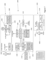
- a weapons targeting training system 1000 (the "training system") as shown in figures 1 and 2 .
- the weapons targeting training system 1000 is for training a ground-based or air-based forward controller 4000 to aim weaponry mounted on an aircraft 3000 at a target 7000.
- the target 7000 is preferably a surface target, such as a ground target or a water target, although air targets are also envisaged.
- the ground-based forward controller 4000 typically has access to a surface terminal 4100 that is able to communicate wirelessly with the training system 1000.
- the surface terminal 4100 is the same as the surface terminal used in actual combat situations, and typically includes a forward controller device 4110, that includes a display screen (not shown) and an input arrangement (not shown) whereby the forward controller is able to input information.
- the surface terminal 4100 further includes a transceiver 4120 configured for wireless communication with the training system 1000.
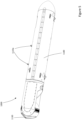
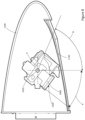
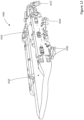
- the weapons targeting training system 1000 is preferably removably mountable to an aircraft 3000 in a pod type housing 1100, as shown in figures 5 and 6 .
- the housing 1100 is mountable to a hard point 3100 typically under the aircraft's wing or on the aircraft's centreline, and preferably to a military pylon (not shown) if this is available on the aircraft that the housing 1100 is being mounted to, in order to facilitate the convenient removability of the housing 1100 from the aircraft 3000.
- the housing 1100 includes connecting formations 1110 configured for mounting the housing 1100 to the hard point 3100.
- Such connecting formations 1110 preferably coincide in shape and configuration with connecting formations currently known in the art for connecting other items to such hard points 3100, although a wide variety of types and configurations of connecting formations are envisaged as being possible.
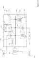
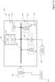
- the training system 1000 includes a wireless transceiver in the form of one or more wireless network interfaces 1200 that is configured for transmitting signals to and receiving signals from the surface terminal 4100, and preferably a ground-based monitoring station 8000.
- the wireless network interface 1200 is also configured for transmitting signals to and receiving signals from a cockpit terminal 5000, preferably in the form of a tablet style mobile computing device (shown in figure 11 ).
- the wireless network interface 1200 of the training system 1000 is also configured for wirelessly receiving signals from and transmitting signals to a helmet mounted display (HMD) arrangement 2000 as will be described in more detail below.
- HMD helmet mounted display
- the communications protocol for wireless communication between the ground-based monitoring station 8000 and the pod 1100 will preferably utilise a wave relay 1210 using an S- Band or L-Band Datalink protocol, and a suitable antenna 1212.
- the communications protocol for wireless communication between the surface terminal 4100 and the training system 1000 will preferably utilise encrypted VHF/UHF voice and data communications, L-Band analog video, and a suitable antenna.
- the wireless network interface 1200 used for shorter range communications between the training system 1000 and the cockpit terminal 5000 and/or weapons rack 1600 as will be described below and/or HMD arrangement 2000, is preferably in the form of a 2.4GHz and/or 5GHz Wi-Fi enabled communications Ethernet router 1220 (or similar communication chip) and associated antenna 1222 as are known in mobile computing devices, utilising one of the IEEE 802.11 wireless protocols, preferably in encrypted format. It is envisaged that alternative forms of wireless transceivers utilising a wide variety of communications protocols and frequencies are possible.
- the wireless network interface 1200 will be configured for communicating with a ground-based or aircraft-based monitoring station 8000 at a weapons training facility (not shown) where the forward controller 4000 is being trained.
- a longer range communications transceiver and protocol is envisaged for communications with a monitoring station 8000, especially if it is ground based.
- the wireless network interface 1200 can preferably be configured for operation using a standard military variable message format (VMF) and voice communications link (HF/VHF/UHF's) and an analog video L-Band link.
- VMF military variable message format
- HF/VHF/UHF's voice communications link
- analog video L-Band link an analog video L-Band link.
- the wireless network interface 1200 will be configured for operation using the S-band or L-Band IP-based datalink protocol that carries H264 encoded video and VMF data to be used by the surface terminal 4100.
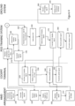
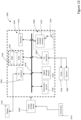
- the training system further includes a controller 1300 in the form of a mission computer housed within the housing 1100. It is envisaged that the controller 1300 will include a processor 1310 as well as a communications bus 1330, random access memory (RAM) 1340, read-only memory (ROM) 1350 and a clock device 1360 for determining time or time lapse.
- the training system 1000 further includes digital storage media 1320 on which data and/or software instructions are storable.
- the digital storage media 1320 is preferably also configured to store digital terrain data, including two-dimensional elevation data.
- the digital storage media 1320 is preferably in the form of solid state device (SSD) memory, with an operating system loaded on it such as Windows TM , Linux TM , OS TM or Android TM , although alternative and/or bespoke operating systems are also envisaged.
- SSD memory is expected to be less susceptible to being affected by g-forces acting on the aircraft and training system 1000.
- the digital storage media 1320 is configured for storage of data, for example in a database, and software instructions (not shown).
- the software instructions are preferably configured for directing the controller to carry out the steps and methods as detailed below.
- the training system 1000 can include an audiovisual interface 1370 for connection to a display, either through a connector (not shown) or the training system 1000 can include a display 1380.
- the training system further includes one or more Input/Output (I/O) interface 1390 for interfacing with internal devices such as a camera 1400, a satellite-based geo-positioning system 1510, an airspeed sensor 1530, one or more accelerometers 1540 and one or more gyroscopes 1550, and/or interfacing with external devices such as a computing device 1395.
- I/O Input/Output
- the digital storage media 1320 can be optical media such as CD-ROM disks, and/or magnetic media such as hard drives, but is preferably provided in the form of one or more flash media or solid-state drives (SSD), which are expected to be less subject to interference by acceleration forces during flight.
- SSD solid-state drives
- Processors referred to in this specification generally can include an arithmetic logic unit, instructions control unit (ICU) and/or processor configured for performing the software or computer program code instructions.
- the software can be embedded on a purpose built digital storage media or can be non-embedded or reconfigurable.
- the processor 1310 may be a reduced instruction set computer (RISC) or complex instruction set computer (CISC) processor or the like.
- RISC reduced instruction set computer
- CISC complex instruction set computer
- the training system 1000 further includes a sensor in the form of an electro-optical and infrared (EO/IR) sensor (hereinafter the "camera") 1400.
- the camera 1400 is preferably able to focus on objects on the ground that give off light and/or heat signatures, and especially on the infrared light from an infrared laser that is being pointed at a target 7000 from the forward controller 4000.
- the camera 1400 is preferably able to provide H.264 and analogue video streams and will have a GPS subsystem 1430 and an ethernet based control interface (not shown) associated with it.
- the camera 1400 is preferably mounted on one or more gimbals 1410 powered by electric motors (not shown) that allow the direction and orientation of the camera to be controlled to rotate around at least one axis (shown as reference X in figure 8 ), and preferably two axes.
- the camera 1400 is preferably movable in a forward/backward direction in a range of between -37° (shown as arrow A in figure 8 ) and +54° (shown as arrow B in figure 8 ) from vertically downwards.
- the range of movement could vary anywhere between -90 and +90, and the camera 1400 could also move from side to side, or in any direction.
- the camera 1400 is also controllable by the controller 1300 to be able to focus on ground targets 7000 at a distance, and has one or more suitable lenses 1420 for this purpose, which are also controllable by the controller 1300 as described in more detail below.
- the camera 1400 will be an EO950 electro optic sensor, including the features of:
- the senor 1400 will be an Alticam TM 14 E0/IR/Laser sensor. It will be appreciated by a person skilled in the art that a wide variety of alternative sensors could be used.
- the training system 1000 can include a power generator (not shown).
- the power generator could be driven by airflow over the housing.
- the power generator could include a solar cell is configured for charging a battery 1710. Examples of such a power generator include air driven turbines, propellers, or the like. It is envisaged that known circuitry would be provided to prevent overcharging of the battery, and the provision of current to the battery in the requisite format.
- the training system 1000 further includes a variety of additional sensors 1500 that are required to carry out its functions.
- the training system includes satellite-based geo-positioning system 1510, for determining the position of the training system 1000 from signals received from geo-positioning satellites.
- the geo-positioning system 1500 is configured for transmitting a position signal to the controller 1300.
- the controller 1300 is preferably also configured for determining the ground speed or velocity of the training system from the change in position over time. Alternatively, the controller 1300 could receive a velocity signal from the geo-positioning system 1500.
- the sensors 1500 preferably also includes an altimeter 1520 configured for transmitting an altitude signal to the controller 1300, and at least one or more airspeed sensors 1530 that is configured for sensing the airspeed of the aircraft 3000.
- the airspeed sensors 1530 are preferably configured for detecting the airspeed of the aircraft in at least two directions.
- the sensors 1500 can include one or more accelerometers 1540 and/or gyroscopes 1550. The use of the sensors 1500 will be described in more detail below. Additionally, voltage, current and temperature sensors may be provided for monitoring temperatures within the housing, as well as battery levels.
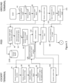
- the software instructions stored on the digital storage media 1320 will be broadly divided into a series of subsystems, including the camera subsystem, health and diagnostic subsystem, power subsystem, cockpit communication subsystem, ground communication subsystem, stores management subsystem and mission computer subsystem.
- the camera subsystem will cover control and management of the camera 1400.
- the health and diagnostic subsystem will ensure ongoing monitoring and diagnostics of the temperatures, functionality and power levels of the training system 1000.
- the cockpit communication subsystem will manage communications between the training system 1000 the cockpit terminal 5000 and the HMD arrangement 2000.
- the mission computer subsystem will manage the rest of the subsystems.
- the mission computer subsystem will further allow for logging of mission data, and allow for access to the digital terrain data and associated data.
- the HMD arrangement 2000 could include any number of input switches or arrangements, including buttons, touch pads, or the like, by which the user could designate a target, receive camera control authorisation input, and/or actuate release of a dummy weapon or weapon by receiving a pickle input,
- a processor with the necessary instructions for carrying out such a method or element of a method forms a means for carrying out the method or element of a method.
- an element described herein of an apparatus embodiment is an example of a means for carrying out the function performed by the element for the purpose of carrying out the invention.
Landscapes
- Engineering & Computer Science (AREA)
- General Engineering & Computer Science (AREA)
- Aviation & Aerospace Engineering (AREA)
- Chemical & Material Sciences (AREA)
- Combustion & Propulsion (AREA)
- Theoretical Computer Science (AREA)
- Physics & Mathematics (AREA)
- Business, Economics & Management (AREA)
- Educational Administration (AREA)
- Educational Technology (AREA)
- General Physics & Mathematics (AREA)
- Electromagnetism (AREA)
- Health & Medical Sciences (AREA)
- General Health & Medical Sciences (AREA)
- Pulmonology (AREA)
- Aiming, Guidance, Guns With A Light Source, Armor, Camouflage, And Targets (AREA)
- Toys (AREA)
- Arrangements For Transmission Of Measured Signals (AREA)
Priority Applications (1)
| Application Number | Priority Date | Filing Date | Title |
|---|---|---|---|
| EP25219815.5A EP4696976A2 (de) | 2019-02-18 | 2020-02-17 | Waffenzieltrainingssystem und verfahren dafür |
Applications Claiming Priority (3)
| Application Number | Priority Date | Filing Date | Title |
|---|---|---|---|
| AU2019900518A AU2019900518A0 (en) | 2019-02-18 | Weapon targeting training system and method therefor | |
| EP20758559.7A EP3928054A4 (de) | 2019-02-18 | 2020-02-17 | Waffenzieltrainingssystem und verfahren dafür |
| PCT/AU2020/050131 WO2020168376A1 (en) | 2019-02-18 | 2020-02-17 | Weapon targeting training system and method therefor |
Related Parent Applications (1)
| Application Number | Title | Priority Date | Filing Date |
|---|---|---|---|
| EP20758559.7A Division EP3928054A4 (de) | 2019-02-18 | 2020-02-17 | Waffenzieltrainingssystem und verfahren dafür |
Related Child Applications (1)
| Application Number | Title | Priority Date | Filing Date |
|---|---|---|---|
| EP25219815.5A Division EP4696976A2 (de) | 2019-02-18 | 2020-02-17 | Waffenzieltrainingssystem und verfahren dafür |
Publications (4)
| Publication Number | Publication Date |
|---|---|
| EP4394307A2 true EP4394307A2 (de) | 2024-07-03 |
| EP4394307A3 EP4394307A3 (de) | 2024-09-18 |
| EP4394307B1 EP4394307B1 (de) | 2025-12-03 |
| EP4394307C0 EP4394307C0 (de) | 2025-12-03 |
Family
ID=72143307
Family Applications (3)
| Application Number | Title | Priority Date | Filing Date |
|---|---|---|---|
| EP20758559.7A Withdrawn EP3928054A4 (de) | 2019-02-18 | 2020-02-17 | Waffenzieltrainingssystem und verfahren dafür |
| EP24170846.0A Active EP4394307B1 (de) | 2019-02-18 | 2020-02-17 | Waffenzieltrainingssystem und verfahren dafür |
| EP25219815.5A Pending EP4696976A2 (de) | 2019-02-18 | 2020-02-17 | Waffenzieltrainingssystem und verfahren dafür |
Family Applications Before (1)
| Application Number | Title | Priority Date | Filing Date |
|---|---|---|---|
| EP20758559.7A Withdrawn EP3928054A4 (de) | 2019-02-18 | 2020-02-17 | Waffenzieltrainingssystem und verfahren dafür |
Family Applications After (1)
| Application Number | Title | Priority Date | Filing Date |
|---|---|---|---|
| EP25219815.5A Pending EP4696976A2 (de) | 2019-02-18 | 2020-02-17 | Waffenzieltrainingssystem und verfahren dafür |
Country Status (9)
| Country | Link |
|---|---|
| US (2) | US20220114906A1 (de) |
| EP (3) | EP3928054A4 (de) |
| JP (1) | JP7538808B2 (de) |
| AU (1) | AU2020225081B2 (de) |
| CA (1) | CA3130461A1 (de) |
| IL (1) | IL285704B2 (de) |
| PH (1) | PH12021551993A1 (de) |
| SG (1) | SG11202108985WA (de) |
| WO (1) | WO2020168376A1 (de) |
Families Citing this family (6)
| Publication number | Priority date | Publication date | Assignee | Title |
|---|---|---|---|---|
| CA3036447A1 (en) * | 2019-03-12 | 2020-09-12 | Motus Design Group Ltd. | Airspeed sensor, system and airspeed monitoring process digitally implemented thereby or in relation thereto |
| GB2590067B8 (en) * | 2019-11-14 | 2023-10-11 | Bae Systems Plc | A weapon system |
| US11983902B1 (en) * | 2020-05-19 | 2024-05-14 | United States Of America As Represented By The Secretary Of The Air Force | Aerospace vehicle comprising module for method of terrain, terrain activity and material classification |
| WO2022235795A2 (en) * | 2021-05-04 | 2022-11-10 | Red Six Aerospace Inc. | Methods, systems, apparatuses, and devices for facilitating provisioning of a virtual experience |
| US20240327027A1 (en) * | 2023-03-31 | 2024-10-03 | Red Six Aerospace Inc. | Augmented reality system for aircraft pilots using third party data |
| CN119027499B (zh) * | 2024-06-17 | 2025-11-21 | 南京理工大学 | 一种基于神经网络的智能辅助瞄准方法及系统 |
Family Cites Families (17)
| Publication number | Priority date | Publication date | Assignee | Title |
|---|---|---|---|---|
| US2278482A (en) * | 1938-05-28 | 1942-04-07 | Republic Aviat Corp | Aircraft armament |
| DE19832612A1 (de) * | 1998-07-21 | 2000-01-27 | Bodenseewerk Geraetetech | Verfahren zum Trainieren eines neuronalen Netzes für die Lenkung eines Flugkörpers zu einem Ziel |
| IL152680A0 (en) | 2002-11-06 | 2003-07-31 | Nir Padan | Real time dynamically controlled elevation and azimuth gun pod mounted on a fixed-wing aerial combat vehicle |
| US7530315B2 (en) * | 2003-05-08 | 2009-05-12 | Lone Star Ip Holdings, Lp | Weapon and weapon system employing the same |
| US8541724B2 (en) * | 2006-09-29 | 2013-09-24 | Lone Star Ip Holdings, Lp | Small smart weapon and weapon system employing the same |
| US8117955B2 (en) * | 2006-10-26 | 2012-02-21 | Lone Star Ip Holdings, Lp | Weapon interface system and delivery platform employing the same |
| US20090040308A1 (en) | 2007-01-15 | 2009-02-12 | Igor Temovskiy | Image orientation correction method and system |
| US8205536B2 (en) * | 2007-06-13 | 2012-06-26 | Efw Inc. | Integrated weapons pod |
| US8009229B1 (en) * | 2007-11-07 | 2011-08-30 | Allen Peterson | Helmet safety system |
| US8616884B1 (en) * | 2009-12-01 | 2013-12-31 | The Boeing Company | Integrated live and simulation environment system for an aircraft |
| US20120150365A1 (en) * | 2010-12-13 | 2012-06-14 | Raytheon Company | Wireless Precision Avionics Kit |
| US20130002525A1 (en) | 2011-06-29 | 2013-01-03 | Bobby Duane Foote | System for locating a position of an object |
| IL239348A0 (en) | 2015-06-11 | 2015-11-30 | Israel Aerospace Ind Ltd | rack |
| US9863739B2 (en) * | 2015-09-22 | 2018-01-09 | The Boeing Company | Vertical drop segmented munitions dispenser |
| US10540007B2 (en) | 2016-03-04 | 2020-01-21 | Rockwell Collins, Inc. | Systems and methods for delivering imagery to head-worn display systems |
| US10670372B2 (en) * | 2017-06-06 | 2020-06-02 | Garmin Switzerland Gmbh | Targeting system |
| US11022403B2 (en) * | 2017-06-06 | 2021-06-01 | Garmin Switzerland Gmbh | Targeting system |
-
2020
- 2020-02-17 JP JP2021549165A patent/JP7538808B2/ja active Active
- 2020-02-17 PH PH1/2021/551993A patent/PH12021551993A1/en unknown
- 2020-02-17 CA CA3130461A patent/CA3130461A1/en active Pending
- 2020-02-17 WO PCT/AU2020/050131 patent/WO2020168376A1/en not_active Ceased
- 2020-02-17 EP EP20758559.7A patent/EP3928054A4/de not_active Withdrawn
- 2020-02-17 IL IL285704A patent/IL285704B2/en unknown
- 2020-02-17 AU AU2020225081A patent/AU2020225081B2/en active Active
- 2020-02-17 EP EP24170846.0A patent/EP4394307B1/de active Active
- 2020-02-17 SG SG11202108985WA patent/SG11202108985WA/en unknown
- 2020-02-17 EP EP25219815.5A patent/EP4696976A2/de active Pending
- 2020-02-17 US US17/310,679 patent/US20220114906A1/en not_active Abandoned
-
2024
- 2024-05-16 US US18/666,656 patent/US20240304102A1/en active Pending
Also Published As
| Publication number | Publication date |
|---|---|
| EP4394307A3 (de) | 2024-09-18 |
| EP3928054A1 (de) | 2021-12-29 |
| AU2020225081B2 (en) | 2024-10-03 |
| AU2020225081A1 (en) | 2021-09-23 |
| SG11202108985WA (en) | 2021-09-29 |
| US20220114906A1 (en) | 2022-04-14 |
| JP2022521523A (ja) | 2022-04-08 |
| EP4696976A2 (de) | 2026-02-18 |
| PH12021551993A1 (en) | 2022-08-08 |
| IL285704B1 (en) | 2024-11-01 |
| JP7538808B2 (ja) | 2024-08-22 |
| CA3130461A1 (en) | 2020-08-27 |
| EP4394307B1 (de) | 2025-12-03 |
| EP4394307C0 (de) | 2025-12-03 |
| US20240304102A1 (en) | 2024-09-12 |
| IL285704B2 (en) | 2025-03-01 |
| EP3928054A4 (de) | 2022-11-09 |
| IL285704A (en) | 2021-10-31 |
| WO2020168376A1 (en) | 2020-08-27 |
Similar Documents
| Publication | Publication Date | Title |
|---|---|---|
| US20240304102A1 (en) | Weapon targeting training system and method therefor | |
| JP6921147B2 (ja) | マルチモードの無人航空機 | |
| CN109425265B (zh) | 飞行器成像与瞄准系统 | |
| EP3447436B1 (de) | Verteidigungsmethode gegen bedrohungen | |
| US11074827B2 (en) | Virtual reality system for aerial vehicle | |
| US12242284B2 (en) | Unmanned system maneuver controller systems and methods | |
| Kubota et al. | An autonomous navigation and guidance system for MUSES-C asteroid landing | |
| US20200080819A1 (en) | Guided munition systems for detecting off-axis targets | |
| US12157583B2 (en) | Flying object coping system, defense information integration center, communication route search device, and flight path prediction device | |
| Bakirci et al. | Avionics system development for a rotary wing unmanned combat aerial vehicle | |
| KR101620404B1 (ko) | Lvc 분산 시뮬레이션 환경을 위한 포드용 내장형 훈련 시스템 | |
| Changey et al. | Electronics and vision system of a projectile-drone hybrid system | |
| RU2319102C1 (ru) | Учебная авиационная бомба с системой инерциально-спутниковой навигации | |
| Panigrahi et al. | Design Principles of Autonomous Systems: UAV, UGV, and AUV | |
| RU117399U1 (ru) | Авиационная система зондирования земной поверхности | |
| Suddarth et al. | VIGILANTE: system description and first experiment approach and results | |
| Müller et al. | Technical description of the MA 2C.’08 MAV |
Legal Events
| Date | Code | Title | Description |
|---|---|---|---|
| PUAI | Public reference made under article 153(3) epc to a published international application that has entered the european phase |
Free format text: ORIGINAL CODE: 0009012 |
|
| STAA | Information on the status of an ep patent application or granted ep patent |
Free format text: STATUS: THE APPLICATION HAS BEEN PUBLISHED |
|
| AC | Divisional application: reference to earlier application |
Ref document number: 3928054 Country of ref document: EP Kind code of ref document: P |
|
| AK | Designated contracting states |
Kind code of ref document: A2 Designated state(s): AL AT BE BG CH CY CZ DE DK EE ES FI FR GB GR HR HU IE IS IT LI LT LU LV MC MK MT NL NO PL PT RO RS SE SI SK SM TR |
|
| PUAL | Search report despatched |
Free format text: ORIGINAL CODE: 0009013 |
|
| REG | Reference to a national code |
Ref country code: DE Ref legal event code: R079 Free format text: PREVIOUS MAIN CLASS: F41G0007220000 Ipc: F41J0005000000 Ref country code: DE Ref legal event code: R079 Ref document number: 602020063516 Country of ref document: DE Free format text: PREVIOUS MAIN CLASS: F41G0007220000 Ipc: F41J0005000000 |
|
| AK | Designated contracting states |
Kind code of ref document: A3 Designated state(s): AL AT BE BG CH CY CZ DE DK EE ES FI FR GB GR HR HU IE IS IT LI LT LU LV MC MK MT NL NO PL PT RO RS SE SI SK SM TR |
|
| RIC1 | Information provided on ipc code assigned before grant |
Ipc: F41G 7/22 20060101ALI20240815BHEP Ipc: F41G 7/00 20060101ALI20240815BHEP Ipc: F41G 3/22 20060101ALI20240815BHEP Ipc: B64D 43/00 20060101ALI20240815BHEP Ipc: B64D 10/00 20060101ALI20240815BHEP Ipc: B64D 1/04 20060101ALI20240815BHEP Ipc: B64D 7/00 20060101ALI20240815BHEP Ipc: B64D 1/02 20060101ALI20240815BHEP Ipc: F41G 3/26 20060101ALI20240815BHEP Ipc: F41A 33/00 20060101ALI20240815BHEP Ipc: F41J 5/00 20060101AFI20240815BHEP |
|
| STAA | Information on the status of an ep patent application or granted ep patent |
Free format text: STATUS: REQUEST FOR EXAMINATION WAS MADE |
|
| 17P | Request for examination filed |
Effective date: 20250318 |
|
| GRAP | Despatch of communication of intention to grant a patent |
Free format text: ORIGINAL CODE: EPIDOSNIGR1 |
|
| STAA | Information on the status of an ep patent application or granted ep patent |
Free format text: STATUS: GRANT OF PATENT IS INTENDED |
|
| RIC1 | Information provided on ipc code assigned before grant |
Ipc: F41J 5/00 20060101AFI20250612BHEP Ipc: F41A 33/00 20060101ALI20250612BHEP Ipc: F41G 3/26 20060101ALI20250612BHEP Ipc: B64D 1/02 20060101ALI20250612BHEP Ipc: B64D 7/00 20060101ALI20250612BHEP Ipc: B64D 1/04 20060101ALI20250612BHEP Ipc: B64D 10/00 20060101ALI20250612BHEP Ipc: B64D 43/00 20060101ALI20250612BHEP Ipc: F41G 3/22 20060101ALI20250612BHEP Ipc: F41G 7/00 20060101ALI20250612BHEP Ipc: F41G 7/22 20060101ALI20250612BHEP |
|
| INTG | Intention to grant announced |
Effective date: 20250626 |
|
| GRAS | Grant fee paid |
Free format text: ORIGINAL CODE: EPIDOSNIGR3 |
|
| GRAA | (expected) grant |
Free format text: ORIGINAL CODE: 0009210 |
|
| STAA | Information on the status of an ep patent application or granted ep patent |
Free format text: STATUS: THE PATENT HAS BEEN GRANTED |
|
| AC | Divisional application: reference to earlier application |
Ref document number: 3928054 Country of ref document: EP Kind code of ref document: P |
|
| AK | Designated contracting states |
Kind code of ref document: B1 Designated state(s): AL AT BE BG CH CY CZ DE DK EE ES FI FR GB GR HR HU IE IS IT LI LT LU LV MC MK MT NL NO PL PT RO RS SE SI SK SM TR |
|
| REG | Reference to a national code |
Ref country code: CH Ref legal event code: F10 Free format text: ST27 STATUS EVENT CODE: U-0-0-F10-F00 (AS PROVIDED BY THE NATIONAL OFFICE) Effective date: 20251203 Ref country code: GB Ref legal event code: FG4D |
|
| REG | Reference to a national code |
Ref country code: DE Ref legal event code: R096 Ref document number: 602020063516 Country of ref document: DE |
|
| REG | Reference to a national code |
Ref country code: IE Ref legal event code: FG4D |
|
| U01 | Request for unitary effect filed |
Effective date: 20260105 |
|
| U07 | Unitary effect registered |
Designated state(s): AT BE BG DE DK EE FI FR IT LT LU LV MT NL PT RO SE SI Effective date: 20260113 |