EP4394280A1 - Apparatus and method for preventing compressor from oil shortage and integrated gas-liquid separator - Google Patents
Apparatus and method for preventing compressor from oil shortage and integrated gas-liquid separator Download PDFInfo
- Publication number
- EP4394280A1 EP4394280A1 EP22860020.1A EP22860020A EP4394280A1 EP 4394280 A1 EP4394280 A1 EP 4394280A1 EP 22860020 A EP22860020 A EP 22860020A EP 4394280 A1 EP4394280 A1 EP 4394280A1
- Authority
- EP
- European Patent Office
- Prior art keywords
- compressor
- flow regulating
- regulating component
- sensor
- oil
- Prior art date
- Legal status (The legal status is an assumption and is not a legal conclusion. Google has not performed a legal analysis and makes no representation as to the accuracy of the status listed.)
- Pending
Links
Images


Classifications
-
- F—MECHANICAL ENGINEERING; LIGHTING; HEATING; WEAPONS; BLASTING
- F25—REFRIGERATION OR COOLING; COMBINED HEATING AND REFRIGERATION SYSTEMS; HEAT PUMP SYSTEMS; MANUFACTURE OR STORAGE OF ICE; LIQUEFACTION SOLIDIFICATION OF GASES
- F25B—REFRIGERATION MACHINES, PLANTS OR SYSTEMS; COMBINED HEATING AND REFRIGERATION SYSTEMS; HEAT PUMP SYSTEMS
- F25B31/00—Compressor arrangements
- F25B31/002—Lubrication
-
- F—MECHANICAL ENGINEERING; LIGHTING; HEATING; WEAPONS; BLASTING
- F25—REFRIGERATION OR COOLING; COMBINED HEATING AND REFRIGERATION SYSTEMS; HEAT PUMP SYSTEMS; MANUFACTURE OR STORAGE OF ICE; LIQUEFACTION SOLIDIFICATION OF GASES
- F25B—REFRIGERATION MACHINES, PLANTS OR SYSTEMS; COMBINED HEATING AND REFRIGERATION SYSTEMS; HEAT PUMP SYSTEMS
- F25B31/00—Compressor arrangements
- F25B31/002—Lubrication
- F25B31/004—Lubrication oil recirculating arrangements
-
- F—MECHANICAL ENGINEERING; LIGHTING; HEATING; WEAPONS; BLASTING
- F25—REFRIGERATION OR COOLING; COMBINED HEATING AND REFRIGERATION SYSTEMS; HEAT PUMP SYSTEMS; MANUFACTURE OR STORAGE OF ICE; LIQUEFACTION SOLIDIFICATION OF GASES
- F25B—REFRIGERATION MACHINES, PLANTS OR SYSTEMS; COMBINED HEATING AND REFRIGERATION SYSTEMS; HEAT PUMP SYSTEMS
- F25B41/00—Fluid-circulation arrangements
- F25B41/20—Disposition of valves, e.g. of on-off valves or flow control valves
-
- F—MECHANICAL ENGINEERING; LIGHTING; HEATING; WEAPONS; BLASTING
- F25—REFRIGERATION OR COOLING; COMBINED HEATING AND REFRIGERATION SYSTEMS; HEAT PUMP SYSTEMS; MANUFACTURE OR STORAGE OF ICE; LIQUEFACTION SOLIDIFICATION OF GASES
- F25B—REFRIGERATION MACHINES, PLANTS OR SYSTEMS; COMBINED HEATING AND REFRIGERATION SYSTEMS; HEAT PUMP SYSTEMS
- F25B41/00—Fluid-circulation arrangements
- F25B41/30—Expansion means; Dispositions thereof
-
- F—MECHANICAL ENGINEERING; LIGHTING; HEATING; WEAPONS; BLASTING
- F25—REFRIGERATION OR COOLING; COMBINED HEATING AND REFRIGERATION SYSTEMS; HEAT PUMP SYSTEMS; MANUFACTURE OR STORAGE OF ICE; LIQUEFACTION SOLIDIFICATION OF GASES
- F25B—REFRIGERATION MACHINES, PLANTS OR SYSTEMS; COMBINED HEATING AND REFRIGERATION SYSTEMS; HEAT PUMP SYSTEMS
- F25B41/00—Fluid-circulation arrangements
- F25B41/30—Expansion means; Dispositions thereof
- F25B41/31—Expansion valves
-
- F—MECHANICAL ENGINEERING; LIGHTING; HEATING; WEAPONS; BLASTING
- F25—REFRIGERATION OR COOLING; COMBINED HEATING AND REFRIGERATION SYSTEMS; HEAT PUMP SYSTEMS; MANUFACTURE OR STORAGE OF ICE; LIQUEFACTION SOLIDIFICATION OF GASES
- F25B—REFRIGERATION MACHINES, PLANTS OR SYSTEMS; COMBINED HEATING AND REFRIGERATION SYSTEMS; HEAT PUMP SYSTEMS
- F25B41/00—Fluid-circulation arrangements
- F25B41/30—Expansion means; Dispositions thereof
- F25B41/31—Expansion valves
- F25B41/34—Expansion valves with the valve member being actuated by electric means, e.g. by piezoelectric actuators
-
- F—MECHANICAL ENGINEERING; LIGHTING; HEATING; WEAPONS; BLASTING
- F25—REFRIGERATION OR COOLING; COMBINED HEATING AND REFRIGERATION SYSTEMS; HEAT PUMP SYSTEMS; MANUFACTURE OR STORAGE OF ICE; LIQUEFACTION SOLIDIFICATION OF GASES
- F25B—REFRIGERATION MACHINES, PLANTS OR SYSTEMS; COMBINED HEATING AND REFRIGERATION SYSTEMS; HEAT PUMP SYSTEMS
- F25B49/00—Arrangement or mounting of control or safety devices
- F25B49/02—Arrangement or mounting of control or safety devices for compression type machines, plants or systems
-
- F—MECHANICAL ENGINEERING; LIGHTING; HEATING; WEAPONS; BLASTING
- F25—REFRIGERATION OR COOLING; COMBINED HEATING AND REFRIGERATION SYSTEMS; HEAT PUMP SYSTEMS; MANUFACTURE OR STORAGE OF ICE; LIQUEFACTION SOLIDIFICATION OF GASES
- F25B—REFRIGERATION MACHINES, PLANTS OR SYSTEMS; COMBINED HEATING AND REFRIGERATION SYSTEMS; HEAT PUMP SYSTEMS
- F25B49/00—Arrangement or mounting of control or safety devices
- F25B49/02—Arrangement or mounting of control or safety devices for compression type machines, plants or systems
- F25B49/022—Compressor control arrangements
-
- F—MECHANICAL ENGINEERING; LIGHTING; HEATING; WEAPONS; BLASTING
- F25—REFRIGERATION OR COOLING; COMBINED HEATING AND REFRIGERATION SYSTEMS; HEAT PUMP SYSTEMS; MANUFACTURE OR STORAGE OF ICE; LIQUEFACTION SOLIDIFICATION OF GASES
- F25B—REFRIGERATION MACHINES, PLANTS OR SYSTEMS; COMBINED HEATING AND REFRIGERATION SYSTEMS; HEAT PUMP SYSTEMS
- F25B2400/00—Component parts or details not otherwise provided for in this subclass
- F25B2400/04—Refrigeration circuit bypassing means
-
- F—MECHANICAL ENGINEERING; LIGHTING; HEATING; WEAPONS; BLASTING
- F25—REFRIGERATION OR COOLING; COMBINED HEATING AND REFRIGERATION SYSTEMS; HEAT PUMP SYSTEMS; MANUFACTURE OR STORAGE OF ICE; LIQUEFACTION SOLIDIFICATION OF GASES
- F25B—REFRIGERATION MACHINES, PLANTS OR SYSTEMS; COMBINED HEATING AND REFRIGERATION SYSTEMS; HEAT PUMP SYSTEMS
- F25B2400/00—Component parts or details not otherwise provided for in this subclass
- F25B2400/23—Separators
-
- F—MECHANICAL ENGINEERING; LIGHTING; HEATING; WEAPONS; BLASTING
- F25—REFRIGERATION OR COOLING; COMBINED HEATING AND REFRIGERATION SYSTEMS; HEAT PUMP SYSTEMS; MANUFACTURE OR STORAGE OF ICE; LIQUEFACTION SOLIDIFICATION OF GASES
- F25B—REFRIGERATION MACHINES, PLANTS OR SYSTEMS; COMBINED HEATING AND REFRIGERATION SYSTEMS; HEAT PUMP SYSTEMS
- F25B2500/00—Problems to be solved
- F25B2500/16—Lubrication
-
- F—MECHANICAL ENGINEERING; LIGHTING; HEATING; WEAPONS; BLASTING
- F25—REFRIGERATION OR COOLING; COMBINED HEATING AND REFRIGERATION SYSTEMS; HEAT PUMP SYSTEMS; MANUFACTURE OR STORAGE OF ICE; LIQUEFACTION SOLIDIFICATION OF GASES
- F25B—REFRIGERATION MACHINES, PLANTS OR SYSTEMS; COMBINED HEATING AND REFRIGERATION SYSTEMS; HEAT PUMP SYSTEMS
- F25B2600/00—Control issues
- F25B2600/25—Control of valves
-
- F—MECHANICAL ENGINEERING; LIGHTING; HEATING; WEAPONS; BLASTING
- F25—REFRIGERATION OR COOLING; COMBINED HEATING AND REFRIGERATION SYSTEMS; HEAT PUMP SYSTEMS; MANUFACTURE OR STORAGE OF ICE; LIQUEFACTION SOLIDIFICATION OF GASES
- F25B—REFRIGERATION MACHINES, PLANTS OR SYSTEMS; COMBINED HEATING AND REFRIGERATION SYSTEMS; HEAT PUMP SYSTEMS
- F25B2600/00—Control issues
- F25B2600/25—Control of valves
- F25B2600/2513—Expansion valves
-
- F—MECHANICAL ENGINEERING; LIGHTING; HEATING; WEAPONS; BLASTING
- F25—REFRIGERATION OR COOLING; COMBINED HEATING AND REFRIGERATION SYSTEMS; HEAT PUMP SYSTEMS; MANUFACTURE OR STORAGE OF ICE; LIQUEFACTION SOLIDIFICATION OF GASES
- F25B—REFRIGERATION MACHINES, PLANTS OR SYSTEMS; COMBINED HEATING AND REFRIGERATION SYSTEMS; HEAT PUMP SYSTEMS
- F25B2600/00—Control issues
- F25B2600/25—Control of valves
- F25B2600/2515—Flow valves
-
- F—MECHANICAL ENGINEERING; LIGHTING; HEATING; WEAPONS; BLASTING
- F25—REFRIGERATION OR COOLING; COMBINED HEATING AND REFRIGERATION SYSTEMS; HEAT PUMP SYSTEMS; MANUFACTURE OR STORAGE OF ICE; LIQUEFACTION SOLIDIFICATION OF GASES
- F25B—REFRIGERATION MACHINES, PLANTS OR SYSTEMS; COMBINED HEATING AND REFRIGERATION SYSTEMS; HEAT PUMP SYSTEMS
- F25B2600/00—Control issues
- F25B2600/25—Control of valves
- F25B2600/2519—On-off valves
-
- F—MECHANICAL ENGINEERING; LIGHTING; HEATING; WEAPONS; BLASTING
- F25—REFRIGERATION OR COOLING; COMBINED HEATING AND REFRIGERATION SYSTEMS; HEAT PUMP SYSTEMS; MANUFACTURE OR STORAGE OF ICE; LIQUEFACTION SOLIDIFICATION OF GASES
- F25B—REFRIGERATION MACHINES, PLANTS OR SYSTEMS; COMBINED HEATING AND REFRIGERATION SYSTEMS; HEAT PUMP SYSTEMS
- F25B2700/00—Sensing or detecting of parameters; Sensors therefor
- F25B2700/03—Oil level
-
- F—MECHANICAL ENGINEERING; LIGHTING; HEATING; WEAPONS; BLASTING
- F25—REFRIGERATION OR COOLING; COMBINED HEATING AND REFRIGERATION SYSTEMS; HEAT PUMP SYSTEMS; MANUFACTURE OR STORAGE OF ICE; LIQUEFACTION SOLIDIFICATION OF GASES
- F25B—REFRIGERATION MACHINES, PLANTS OR SYSTEMS; COMBINED HEATING AND REFRIGERATION SYSTEMS; HEAT PUMP SYSTEMS
- F25B2700/00—Sensing or detecting of parameters; Sensors therefor
- F25B2700/19—Pressures
-
- F—MECHANICAL ENGINEERING; LIGHTING; HEATING; WEAPONS; BLASTING
- F25—REFRIGERATION OR COOLING; COMBINED HEATING AND REFRIGERATION SYSTEMS; HEAT PUMP SYSTEMS; MANUFACTURE OR STORAGE OF ICE; LIQUEFACTION SOLIDIFICATION OF GASES
- F25B—REFRIGERATION MACHINES, PLANTS OR SYSTEMS; COMBINED HEATING AND REFRIGERATION SYSTEMS; HEAT PUMP SYSTEMS
- F25B2700/00—Sensing or detecting of parameters; Sensors therefor
- F25B2700/21—Temperatures
-
- F—MECHANICAL ENGINEERING; LIGHTING; HEATING; WEAPONS; BLASTING
- F25—REFRIGERATION OR COOLING; COMBINED HEATING AND REFRIGERATION SYSTEMS; HEAT PUMP SYSTEMS; MANUFACTURE OR STORAGE OF ICE; LIQUEFACTION SOLIDIFICATION OF GASES
- F25B—REFRIGERATION MACHINES, PLANTS OR SYSTEMS; COMBINED HEATING AND REFRIGERATION SYSTEMS; HEAT PUMP SYSTEMS
- F25B43/00—Arrangements for separating or purifying gases or liquids; Arrangements for vaporising the residuum of liquid refrigerant, e.g. by heat
- F25B43/02—Arrangements for separating or purifying gases or liquids; Arrangements for vaporising the residuum of liquid refrigerant, e.g. by heat for separating lubricants from the refrigerant
-
- Y—GENERAL TAGGING OF NEW TECHNOLOGICAL DEVELOPMENTS; GENERAL TAGGING OF CROSS-SECTIONAL TECHNOLOGIES SPANNING OVER SEVERAL SECTIONS OF THE IPC; TECHNICAL SUBJECTS COVERED BY FORMER USPC CROSS-REFERENCE ART COLLECTIONS [XRACs] AND DIGESTS
- Y02—TECHNOLOGIES OR APPLICATIONS FOR MITIGATION OR ADAPTATION AGAINST CLIMATE CHANGE
- Y02B—CLIMATE CHANGE MITIGATION TECHNOLOGIES RELATED TO BUILDINGS, e.g. HOUSING, HOUSE APPLIANCES OR RELATED END-USER APPLICATIONS
- Y02B30/00—Energy efficient heating, ventilation or air conditioning [HVAC]
- Y02B30/70—Efficient control or regulation technologies, e.g. for control of refrigerant flow, motor or heating
Definitions
- the gas-liquid separator, the stopping valve, the first sensor, the second flow regulating component and the second sensor are integrated.
- the disclosure provides a method for preventing a compressor from oil shortage, which includes: detecting oil content of a low-pressure side of the compressor through the oil content detecting assembly, and transmitting a detecting result to the controller; the controller determining whether the compressor is in the oil shortage according to the detecting result; and the controller turning off the stopping valve and the first flow regulating component and controlling an operation of the compressor simultaneously when the compressor lacks oil to realize an oil return.
- the disclosure provides an integrated gas-liquid separator, which includes a gas-liquid separator body, the second flow regulating component, a first sensor, a second sensor and the stopping valve.
- the gas-liquid separator body is provided with a first outlet inside and a second outlet at an end part of the gas-liquid separator body, a first tube and a bypass are arranged between the first outlet and the second outlet, and the first tube is connected in parallel with the bypass.
- the second flow regulating component is arranged on the bypass.
- the first sensor is arranged on the bypass and located an upstream of the second flow regulating component.
- the second sensor is arranged on the bypass and located a downstream of the second flow regulating component.
- the stopping valve is arranged at an end part of the gas-liquid separator body and configured to control tubes between the compressor and the condenser.
- the gas-liquid separator body is further integrated with a controller, and the controller is configured to receive signals of the first sensor and the second sensor, and control the first flow regulating component.
- the disclosure detects the oil content of the low-pressure side of the compressor through the oil content detecting assembly, and transmits the detecting result to the controller.
- the controller controls the stopping valve and the first flow regulating component to be turned off and controls the compressor to run.
- the compressor relies on its pumping power to suck the oil in the evaporator and oil content detecting assembly into itself, thereby realizing the oil return. Therefore, the disclosure can effectively improve a problem that the conventional compressor lacks oil in the heating mode or the refrigeration mode.
- the disclosure further provides a detecting method for the compressor oil shortage, which is easy to implement, has accurate results, and ensures that the oil content of the compressor is within an appropriate range.
- the disclosure further provides the integrated gas-liquid separator that integrates an oil content detecting module and the stopping valve to detect the oil content of the compressor in real time, which ensures a safety of the compressor and improves a degree of a system integration.
- 1-stopping valve 2-first flow regulating component, 3-oil content detecting assembly, 4-controller, 5-compressor, 6-condenser, 7-evaporator, 8-gas-liquid separator, 9-first sensor, 10-second flow regulating component, 11-second sensor, 12-closed circuit, 13-bypass, 14-integrated gas-liquid separator, 15-gas-liquid separator body, 16-first outlet, 17-second outlet, 18-first tube, 19-air return inlet, 20-inlet, 21-outlet.
- the return air of the compressor 5 includes refrigerant and oil.
- the controller 4 may determine a proportion of an oil content (0-100%) of return air according to a degree of temperature change, and determine whether the compressor 5 is in an oil shortage state by this.
- the first sensor 9 and the second sensor 11 upload the detecting result to the controller 4 in real time, which realizes a real-time detection of the oil content of the compressor 5 by the controller 4.
- the disclosure further provides a method to prevent the compressor oil shortage, which includes: detecting oil content of a low-pressure side of the compressor through the oil content detecting assembly, and transmitting a detecting result to the controller; the controller determining whether the compressor lacks oil according to the detecting result; and when the detecting result is that the compressor lacks oil, the controller turning off the stopping valve and the first flow regulating component, and controlling an operation of the compressor simultaneously to realize an oil return.
- the controller turns on the stopping valve and the first flow regulating component.
Landscapes
- Engineering & Computer Science (AREA)
- Physics & Mathematics (AREA)
- Mechanical Engineering (AREA)
- Thermal Sciences (AREA)
- General Engineering & Computer Science (AREA)
- Applications Or Details Of Rotary Compressors (AREA)
- Control Of Positive-Displacement Pumps (AREA)
- Compressor (AREA)
Abstract
Description
- The disclosure relates to a field of vehicle interior air conditioning, specifically relates to a device and a method for preventing a compressor from oil shortage and an integrated gas-liquid separator.
- Heat pump systems are increasingly being used in the air conditioning of electric vehicles. However, the heat pump system has the following problems in a low-temperature heat pump heating mode or a refrigeration mode that due to a low ambient temperature, the viscosity of the refrigerant on the low pressure side is high, which enables the compressor oil dissolved in the refrigerant, and the compressor oil return is difficult, which eventually leads to a compressor oil shortage or even a damage accident. At the same time, the conventional heat pump systematization cannot effectively diagnose the difficulty of compressor oil return and whether the compressor lacks oil, and there is no mature detecting method for the compressor oil content.
- The disclosure provides a device and a method for preventing a compressor from oil shortage and an integrated gas-liquid separator to improve a problem of oil shortage in conventional compressors in a heating mode or a cooling mode.
- The disclosure provides the device for preventing a compressor from oil shortage. The device includes a stopping valve, a first flow regulating component, an oil content detecting assembly, and a controller. Wherein, the stopping valve is arranged on a first communicating tube between the compressor and a condenser. The first flow regulating component is arranged on a second communicating tube between the condenser and an evaporator. The oil content detecting assembly is arranged on a third communicating tube between the evaporator and the compressor. The controller is configured to receive a signal of the oil content detecting assembly and control the stopping valve and the first flow regulating component.
- In an embodiment of the disclosure, the oil content detecting assembly comprises a gas-liquid separator, a first sensor, a second flow regulating component, and a second sensor, the gas-liquid separator is connected with the evaporator and the compressor respectively, a bypass is arranged on a passage between the gas-liquid separator and the compressor, the second flow regulating component is arranged on the bypass, the first sensor is located at an upstream of the second flow regulating component, the second sensor is located on the bypass and is located at a downstream of the second flow regulating component, and the first sensor and the second sensor respectively transmit detected information to the controller.
- In an embodiment of the disclosure, the stopping valve is an electromagnetic control valve.
- In an embodiment of the disclosure, a first flow regulating component is an electronic expansion valve.
- In an embodiment of the disclosure, the first flow regulating component comprises a thermal expansion valve and a first controlling valve, the thermal expansion valve is connected in series with the first controlling valve, the first controlling valve is controlled by the controller, and the first controlling valve may be the stopping valve.
- In an embodiment of the disclosure, the first flow regulating component comprises a short throttle tube and a second controlling valve, the thermal expansion valve is connected in series with the second controlling valve, the second controlling valve is controlled by the controller, and the second controlling valve may be the stopping valve.
- In an embodiment of the disclosure, the second flow regulating component is one of the electronic expansion valve, the thermal expansion valve or the short throttle tube.
- In an embodiment of the disclosure, the first sensor and/or the second sensor are pressure-temperature sensors.
- In an embodiment of the disclosure, the gas-liquid separator, the stopping valve, the first sensor, the second flow regulating component and the second sensor are integrated.
- The disclosure provides a method for preventing a compressor from oil shortage, which includes: detecting oil content of a low-pressure side of the compressor through the oil content detecting assembly, and transmitting a detecting result to the controller; the controller determining whether the compressor is in the oil shortage according to the detecting result; and the controller turning off the stopping valve and the first flow regulating component and controlling an operation of the compressor simultaneously when the compressor lacks oil to realize an oil return.
- In an embodiment of the disclosure, the method further includes: turning on the stopping valve and the first flow regulating component when the compressor is in the oil shortage and a closing time of the stopping valve reaches a set threshold.
- The disclosure provides an integrated gas-liquid separator, which includes a gas-liquid separator body, the second flow regulating component, a first sensor, a second sensor and the stopping valve. The gas-liquid separator body is provided with a first outlet inside and a second outlet at an end part of the gas-liquid separator body, a first tube and a bypass are arranged between the first outlet and the second outlet, and the first tube is connected in parallel with the bypass. The second flow regulating component is arranged on the bypass. The first sensor is arranged on the bypass and located an upstream of the second flow regulating component. The second sensor is arranged on the bypass and located a downstream of the second flow regulating component. The stopping valve is arranged at an end part of the gas-liquid separator body and configured to control tubes between the compressor and the condenser.
- In an embodiment of the disclosure, the gas-liquid separator body is further integrated with a controller, and the controller is configured to receive signals of the first sensor and the second sensor, and control the first flow regulating component.
- In summary, the disclosure detects the oil content of the low-pressure side of the compressor through the oil content detecting assembly, and transmits the detecting result to the controller. When the compressor lacks oil, the controller controls the stopping valve and the first flow regulating component to be turned off and controls the compressor to run. During operation, the compressor relies on its pumping power to suck the oil in the evaporator and oil content detecting assembly into itself, thereby realizing the oil return. Therefore, the disclosure can effectively improve a problem that the conventional compressor lacks oil in the heating mode or the refrigeration mode.
- In addition, the disclosure further provides a detecting method for the compressor oil shortage, which is easy to implement, has accurate results, and ensures that the oil content of the compressor is within an appropriate range. At the same time, the disclosure further provides the integrated gas-liquid separator that integrates an oil content detecting module and the stopping valve to detect the oil content of the compressor in real time, which ensures a safety of the compressor and improves a degree of a system integration.
- In order to explain technical solutions of embodiments of the disclosure more clearly, the following will briefly introduce drawings used in a description of the embodiments or the conventional art. Obviously, the drawings in the following description are only some embodiments of the disclosure. For those of ordinary skill in the art, other drawings may be obtained based on these drawings without creative work.
-
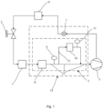
FIG. 1 is a schematic structural view of a device for preventing a compressor from an oil shortage according to an embodiment of the disclosure. -
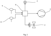
FIG. 2 is a schematic electrical connection view of a device for preventing a compressor from an oil shortage of the disclosure. -
FIG. 3 is a schematic flowchart of a method for preventing a compressor from an oil shortage according to an embodiment of the disclosure. -
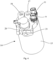
FIG. 4 is a schematic structural view of an integrated gas-liquid separator according to an embodiment of the disclosure. -
FIG. 5 is a cross-sectional view of an end part of the integrated gas-liquid separator according to an embodiment of the disclosure. -
FIG. 6 is a cross-sectional view of an SOV stopping valve according to an embodiment of the disclosure. - 1-stopping valve, 2-first flow regulating component, 3-oil content detecting assembly, 4-controller, 5-compressor, 6-condenser, 7-evaporator, 8-gas-liquid separator, 9-first sensor, 10-second flow regulating component, 11-second sensor, 12-closed circuit, 13-bypass, 14-integrated gas-liquid separator, 15-gas-liquid separator body, 16-first outlet, 17-second outlet, 18-first tube, 19-air return inlet, 20-inlet, 21-outlet.
- The following describes the implementation of the disclosure through specific embodiments, and those skilled in the art can easily understand other advantages and effects of the disclosure from the content disclosed in this specification. The disclosure may also be implemented or applied through other different specific embodiments. Various details in this specification may also be modified or changed based on different viewpoints and applications without departing from the disclosure. It should be noted that, the following embodiments and the features in the embodiments can be combined with each other without conflict. It should further be understood that the terms used in the examples of the disclosure are used to describe specific embodiments, instead of limiting the protection scope of the disclosure. The test methods that do not indicate specific conditions in the following examples are usually in accordance with conventional conditions, or conditions recommended by each manufacturer.
- Please refer to
FIG. 1 through FIG. 6 . It should be noted that the structure, proportion, size, etc. shown in the drawings attached to this specification are only used to cooperate with the contents disclosed in the description for the understanding and reading of persons familiar with the technology, and are not used to limit the limitations that may be implemented by the disclosure, so there is no technical substantive significance. Any structural modifications, changes in proportion, or adjustments in size should still fall within the scope of the technical content disclosed in the disclosure without affecting the effectiveness and purpose of the disclosure. At the same time, it should be noted that terms "upper", "lower", "left", "right", "middle" and "one" quoted in this specification are only for a convenience of description, and are not used to limit a scope of the disclosure. Changes or adjustments in their relative relationships shall also be regarded to be within the scope of the disclosure when there is no substantial change in the technical content. - When an embodiment gives a range of values, it should be understood that, unless otherwise specified in the disclosure, two endpoints of each range of values and any one of the values between the two endpoints may be selected. Unless otherwise defined, all technical and scientific terms used in the disclosure and the prior art mastered by a person skilled in the art and a description of the disclosure may also be realized by using any method, equipment and material similar to or equivalent to the prior art described in the embodiments of the disclosure.
- Please refer to
FIG. 1 through FIG. 2 . The disclosure provides a device, a method and an integrated gas-liquid separator to prevent a compressor oil shortage to improve a problem of oil shortage in conventional compressors in a heating mode or a cooling mode. The device to prevent a compressor oil shortage includes a stopping valve 1, a firstflow regulating component 2, an oilcontent detecting assembly 3, and acontroller 4. Wherein, the stopping valve is arranged on a first communicating tube between thecompressor 5 and acondenser 6. The firstflow regulating component 2 is arranged on a second communicating tube between thecondenser 6 and anevaporator 7. The oilcontent detecting assembly 3 is arranged on a third communicating tube between theevaporator 7 and thecompressor 5. Thecontroller 4 receives a signal of the oilcontent detecting assembly 3 and controls the stopping valve 1 and the firstflow regulating component 2. - The oil
content detecting assembly 3 is arranged on a low-pressure return air side of thecompressor 5, used for detecting the oil content and transmitting a detecting result to thecontroller 4. Thecontroller 4 determines whether thecompressor 5 is short of oil according to the detecting result. When thecompressor 5 is short of the oil, thecontroller 4 closes the stopping valve 1 and the firstflow regulating component 2 and runs thecompressor 5. Thecompressor 5 relies on its pumping power to suck the oil in theevaporator 7 and the oilcontent detecting assembly 3 to realize oil return and improve an oil shortage situation. - Please refer to
FIG. 1 . The oilcontent detecting assembly 3 includes a gas-liquid separator 8, afirst sensor 9, a secondflow regulating component 10, and asecond sensor 11, and the gas-liquid separator 8 is connected with theevaporator 7 and thecompressor 5 respectively. Abypass 13 is arranged on apassage 12 between the gas-liquid separator 8 and thecompressor 5, and the secondflow regulating component 10 is arranged on thebypass 13. Thefirst sensor 9 is located at an upstream of the secondflow regulating component 10, for example, arranged on thepassage 12 between the gas-liquid separator 8 and thecompressor 5 and located at an upstream of thebypass 13; or arranged on thebypass 13 and located at an upstream of the secondflow adjustment part 10. Thesecond sensor 11 is located on thebypass 13 and is located at a downstream of the secondflow regulating component 10, and thefirst sensor 9 and thesecond sensor 11 respectively transmit detected information to thecontroller 4. - The return air of the
compressor 5 includes refrigerant and oil. When the refrigerant encounters the secondflow regulating component 10, its temperature may change, while a temperature of the oil does not change, so thecontroller 4 may determine a proportion of an oil content (0-100%) of return air according to a degree of temperature change, and determine whether thecompressor 5 is in an oil shortage state by this. Thefirst sensor 9 and thesecond sensor 11 upload the detecting result to thecontroller 4 in real time, which realizes a real-time detection of the oil content of thecompressor 5 by thecontroller 4. When thecompressor 5 is detected to be in the oil shortage state, thecontroller 4 controls an operation of thecompressor 5, and thecompressor 5 relies on its own pumping power to suck the oil in the gas-liquid separator 8 and theevaporator 7 into thecompressor 5, so as to realize the oil return, thereby alleviating the oil shortage of thecompressor 5. - In an embodiment of the disclosure, the stopping valve 1 is an electromagnetic control valve, which means an SOV (Solenoid Operated Valve) stopping valve. The SOV stopping valve is simple in structure, low cost, easy to control, and conducive to an integration with the gas-liquid separator. The first
flow regulating component 2 is an electronic expansion valve. The secondflow regulating component 10 is one of the electronic expansion valve, the thermal expansion valve and the short throttle tube. - In an embodiment of the disclosure, the first flow regulating component includes a thermal expansion valve and a first controlling valve, the thermal expansion valve connects in series with the first controlling valve, the first controlling valve is controlled by the controller, and the first controlling valve may be the stopping valve.
- In an embodiment of the disclosure, the first flow regulating component includes a short throttle tube and a second controlling valve, the short throttle tube connects in series with the second controlling valve, the second controlling valve is controlled by the controller, and the second controlling valve may be the stopping valve.
- Please refer to
FIG. 1 . In an embodiment of the disclosure, thefirst sensor 9 and/or thesecond sensor 11 are pressure-temperature sensors. Thefirst sensor 9 is used for detecting a temperature and pressure of the upstream of the secondflow regulating component 10, and transmits a result to thecontroller 4. Thesecond sensor 11 is used for detecting a temperature and pressure of thebypass 13 after being regulated by the secondflow regulating component 10, and transmits the result to thecontroller 4. Thecontroller 4 determines the oil content of the return air of thecompressor 5 according to the detecting results of the two sensors, and determines whether thecompressor 5 is short of oil based on this. A signal transmission between two sensors and thecontroller 4 may be transmitted in a wired mode or in a wireless mode, wherein the wired mode may be a signal line connection or an electrical connection, and the wireless mode may be a Bluetooth, infrared, radio, communication network (such as 2G, 4G, 5G etc.) or broadband wireless network etc. - Please refer to
FIG. 1 ,FIG. 4 andFIG. 5 . In an embodiment of the disclosure, the gas-liquid separator 8, the stopping valve 1, thefirst sensor 9, the secondflow regulating component 10, thesecond sensor 11 and thebypass 13 are integrated. An integration mode may adopt a following integration mode of an integrated gas-liquid separator 14, wherein the gas-liquid separator 8 is equivalent to a gas-liquid separator body 15. A followingfirst tube 18 is a part of thepassage 12 described in this embodiment. - Please refer to
FIG. 3 . The disclosure further provides a method to prevent the compressor oil shortage, which includes: detecting oil content of a low-pressure side of the compressor through the oil content detecting assembly, and transmitting a detecting result to the controller; the controller determining whether the compressor lacks oil according to the detecting result; and when the detecting result is that the compressor lacks oil, the controller turning off the stopping valve and the first flow regulating component, and controlling an operation of the compressor simultaneously to realize an oil return. When the oil content in the return air of the compressor returns to a normal range, the controller turns on the stopping valve and the first flow regulating component. - Please refer to
FIG. 3 . In an embodiment of the disclosure, the method further includes: when the detecting result is that the compressor is not short of oil, the stopping valve and the first flow regulating part remain are kept being on. - Please refer to
FIG. 3 . In an embodiment of the disclosure, the method further includes: when the compressor lacks oil and a closing time of the stopping valve reaches a set threshold, then turning on the stopping valve and the first flow regulating component. The set threshold is less than or equal to two minutes. In order to ensure a safe operation of the compressor, under a condition of the oil shortage of thecompressor 5, a closing time of SOV stopping valve is from 10S to 20S, and a low-frequency speed of thecompressor 5 is less than or equal to 2000 rpm/min. - Please refer to
FIG. 4 through FIG. 5 . The disclosure further provides the integrated gas-liquid separator 14 that integrates the stopping valve 1 and the oilcontent detecting assembly 3. The integrated gas-liquid separator 14 includes the gas-liquid separator body 15, the secondflow regulating component 10, thefirst sensor 9, thesecond sensor 11 and the stopping valve 1. Wherein, the gas-liquid separator body 15 is provided with a first outlet inside 16 and asecond outlet 17 at its end part. Afirst tube 18 and thebypass 13 are arranged between thefirst outlet 16 and thesecond outlet 17, and thefirst tube 18 is connected in parallel with thebypass 13. The secondflow regulating component 10 is arranged on thebypass 13. Thefirst sensor 9 is arranged on thebypass 13 and located at the upstream of the secondflow regulating component 10. Thesecond sensor 11 is arranged on thebypass 13 and located at the downstream of the secondflow regulating component 10. The stopping valve 1 is arranged at an end part of the gas-liquid separator body 15 and controls tubes between thecompressor 5 and thecondenser 6. - Please refer to
FIG. 4 through FIG. 6 . The end part of the gas-liquid separator body 15 is further provided withair return inlet 19, and the return air enters the gas-liquid separator body 15 from theair return inlet 19, flows out from thefirst outlet 16, and then flows into thesecond outlet 17 through thefirst tube 18 and thebypass 13. Thesecond outlet 17 is a total outlet and is used for connecting with thecompressor 5. The stopping valve 1 is provided with aninlet 20 and anoutlet 21, and theinlet 20 is perpendicular to theoutlet 21. - In an embodiment of the disclosure, the integrated gas-liquid separator further includes the controller 4 (not labeled). The
controller 4 is detachably arranged on the gas-liquid separator body 15 and used to receive the detection signal of thefirst sensor 9 and thesecond sensor 11 and control the firstflow regulating component 2. The firstflow regulating component 2 is arranged on the tube between thecondenser 6 and theevaporator 7. Through the above-mentioned integrated gas-liquid separator, a problem of oil shortage in the compressor can be effectively solved. When an application environment permits, the controller may be integrated on the gas-liquid separator body to improve a degree of integration and save space. To further increase a range of applications, the controller may be integrated into a total control system of a vehicle console. - In an embodiment of the disclosure, the
first sensor 9 and/or thesecond sensor 11 are the pressure-temperature sensors. Thefirst sensor 9 is used for detecting a temperature and pressure of thebypass 13 before regulated by the secondflow regulating component 10, and transmitting the result to the controller. Thesecond sensor 11 is used for detecting the temperature and pressure of thebypass 13 after being regulated by the secondflow regulating component 10, and transmitting the result to thecontroller 4. Thecontroller 4 determines the oil content of the return air of the compressor according to the detecting results of the two sensors, and determines whether the compressor is short of oil based on this. A signal transmission between two sensors and the controller may be transmitted in the wired mode or in the wireless mode, wherein the wired mode may be the signal line connection or an electrical connection, and the wireless mode may be the Bluetooth, infrared, radio, communication network (such as 2G, 4G, 5G etc.) or broadband wireless network etc. - In summary, the disclosure detects the oil content of the low-pressure side of the
compressor 4 through the oilcontent detecting assembly 3, and transmits the detecting result to thecontroller 4. When thecompressor 5 lacks oil, thecontroller 4 controls to turn off the stopping valve 1 and the firstflow regulating component 2, and runs thecompressor 5. During operation, thecompressor 5 relies on its pumping power to suck the oil in theevaporator 7 and the gas-liquid separator 8 into itself, thereby realizing the oil return. Therefore, the disclosure can effectively improve a problem that the conventional compressor lacks oil in the heating mode or the refrigeration mode. Therefore, the disclosure effectively overcomes some practical problems in the prior art, thereby having high utilization value and use significance. - The above embodiments only illustrate principles and effects of the disclosure, but are not intended to limit the disclosure. Anyone familiar with this technology may modify or change the above embodiments without departing from a scope of the disclosure. Therefore, all equivalent modifications or changes made by those with ordinary knowledge in the technical field without departing from the technical ideas disclosed in the disclosure shall still be covered by the claims of the disclosure.
Claims (10)
- A device for preventing a compressor from an oil shortage, comprising:a stopping valve, arranged on a first communicating tube between the compressor and a condenser;a first flow regulating component, arranged on a second communicating tube between the condenser and an evaporator;an oil content detecting assembly, arranged on a third communicating tube between the evaporator and the compressor; anda controller, configured to receive a signal of the oil content detecting assembly and control the stopping valve, the first flow regulating component and the compressor.
- The device for preventing a compressor from an oil shortage according to claim 1, wherein, the oil content detecting assembly comprises a gas-liquid separator, a first sensor, a second flow regulating component, and a second sensor, the gas-liquid separator is connected with the evaporator and the compressor respectively, a bypass is arranged on a passage between the gas-liquid separator and the compressor, the second flow regulating component is arranged on the bypass, the first sensor is located at an upstream of the second flow regulating component, the second sensor is located on the bypass and is located at a downstream of the second flow regulating component, and the first sensor and the second sensor respectively transmit detected information to the controller.
- The device for preventing a compressor from an oil shortage according to claim 1, wherein, the stopping valve is an electromagnetic control valve.
- The device for preventing a compressor from an oil shortage according to claim 1, wherein, the first flow regulating component is an electronic expansion valve.
- The device for preventing a compressor from an oil shortage according to claim 2, wherein, the second flow regulating component is one of an electronic expansion valve, a thermal expansion valve or a short throttle tube.
- The device for preventing a compressor from an oil shortage according to claim 2, wherein, the first sensor and/or the second sensor are pressure-temperature sensors.
- The device for preventing a compressor from an oil shortage according to claim 2, wherein, the gas-liquid separator, the stopping valve, the first sensor, the second flow regulating component and the second sensor are integrated.
- A method implemented by the device in any one of claims 1 to 7, comprising:detecting oil content of a low-pressure side of the compressor through the oil content detecting assembly, and transmitting a detecting result to the controller;the controller determining whether the compressor is in oil shortage according to the detecting result; andthe controller turning off the stopping valve and the first flow regulating component and controlling an operation of the compressor simultaneously when the compressor lacks oil, so as to realize an oil return.
- The method according to claim 8, further comprising: turning on the stopping valve and the first flow regulating component when the compressor is in oil shortage and a closing time of the stopping valve reaches a set threshold,.
- An integrated gas-liquid separator, comprising:a gas-liquid separator body, provided with a first outlet inside and a second outlet at an end part of the gas-liquid separator body, a first tube and a bypass being arranged between the first outlet and the second outlet, and the first tube being connected in parallel with the bypass;a second flow regulating component, arranged on the bypass;a first sensor, arranged on the bypass and located an upstream of the second flow regulating component;a second sensor, arranged on the bypass and located a downstream of the second flow regulating component; anda stopping valve, arranged at an end part of the gas-liquid separator body and configured to control tubes between the compressor and the condenser.
Applications Claiming Priority (2)
| Application Number | Priority Date | Filing Date | Title |
|---|---|---|---|
| CN202110988066.6A CN113654275B (en) | 2021-08-26 | 2021-08-26 | Device, method and integrated gas-liquid separator for preventing compressor oil shortage |
| PCT/CN2022/099793 WO2023024673A1 (en) | 2021-08-26 | 2022-06-20 | Apparatus and method for preventing compressor from oil shortage and integrated gas-liquid separator |
Publications (2)
| Publication Number | Publication Date |
|---|---|
| EP4394280A1 true EP4394280A1 (en) | 2024-07-03 |
| EP4394280A4 EP4394280A4 (en) | 2025-10-22 |
Family
ID=78492965
Family Applications (1)
| Application Number | Title | Priority Date | Filing Date |
|---|---|---|---|
| EP22860020.1A Pending EP4394280A4 (en) | 2021-08-26 | 2022-06-20 | Device and method for preventing oil starvation in a compressor and integrated gas-liquid separator |
Country Status (4)
| Country | Link |
|---|---|
| EP (1) | EP4394280A4 (en) |
| KR (1) | KR20240047420A (en) |
| CN (1) | CN113654275B (en) |
| WO (1) | WO2023024673A1 (en) |
Families Citing this family (2)
| Publication number | Priority date | Publication date | Assignee | Title |
|---|---|---|---|---|
| CN113654275B (en) * | 2021-08-26 | 2023-08-22 | 浙江吉利控股集团有限公司 | Device, method and integrated gas-liquid separator for preventing compressor oil shortage |
| CN116373553B (en) * | 2023-03-21 | 2025-10-21 | 浙江联控技术有限公司 | Air conditioning system oil return control method, automobile heat pump air conditioning system and electric vehicle |
Family Cites Families (12)
| Publication number | Priority date | Publication date | Assignee | Title |
|---|---|---|---|---|
| JP3448794B2 (en) * | 1995-06-16 | 2003-09-22 | 三菱電機株式会社 | Refrigeration equipment |
| JP5078085B2 (en) * | 2007-11-29 | 2012-11-21 | 株式会社チノー | Oil circulation rate measuring apparatus and method |
| CN101338961A (en) * | 2008-08-18 | 2009-01-07 | 南京天加空调设备有限公司 | Automatic oil return control method and device for refrigeration system |
| CN102980327B (en) * | 2012-12-14 | 2015-09-23 | 四川长虹空调有限公司 | Lubricating Oil level detecting apparatus and method in air-conditioning system |
| CN104089347B (en) * | 2014-06-24 | 2017-04-12 | 广东申菱环境系统股份有限公司 | Low-temperature air-cooled water chiller unit and control method thereof |
| CN104764253A (en) * | 2015-03-31 | 2015-07-08 | 广东美的暖通设备有限公司 | Refrigerating system |
| CN105066494B (en) * | 2015-08-27 | 2018-06-22 | 广东申菱环境系统股份有限公司 | One seed nucleus grade directly evaporates combined air processing group and its control method |
| CN105156317B (en) * | 2015-10-15 | 2018-07-03 | 珠海格力电器股份有限公司 | Compressor oil level detection device, air conditioning system and compressor oil level detection method |
| CN109916106B (en) * | 2019-04-25 | 2024-02-27 | 南京天加环境科技有限公司 | Heat pump air conditioner unit capable of controlling temperature of lubricating oil and control method thereof |
| CN212481755U (en) * | 2020-06-09 | 2021-02-05 | 北京金茂绿建科技有限公司 | Oil level detection protection device for compressor and heat pump system |
| CN113654275B (en) * | 2021-08-26 | 2023-08-22 | 浙江吉利控股集团有限公司 | Device, method and integrated gas-liquid separator for preventing compressor oil shortage |
| CN113803919B (en) * | 2021-09-30 | 2022-09-27 | 浙江吉利控股集团有限公司 | Rotating speed control method, system, equipment and storage medium |
-
2021
- 2021-08-26 CN CN202110988066.6A patent/CN113654275B/en active Active
-
2022
- 2022-06-20 WO PCT/CN2022/099793 patent/WO2023024673A1/en not_active Ceased
- 2022-06-20 KR KR1020247008280A patent/KR20240047420A/en active Pending
- 2022-06-20 EP EP22860020.1A patent/EP4394280A4/en active Pending
Also Published As
| Publication number | Publication date |
|---|---|
| WO2023024673A1 (en) | 2023-03-02 |
| CN113654275A (en) | 2021-11-16 |
| EP4394280A4 (en) | 2025-10-22 |
| KR20240047420A (en) | 2024-04-12 |
| CN113654275B (en) | 2023-08-22 |
Similar Documents
| Publication | Publication Date | Title |
|---|---|---|
| US8151583B2 (en) | Expansion valve control system and method for air conditioning apparatus | |
| US11448441B2 (en) | Refrigerant system for cooling electronics | |
| CN201348340Y (en) | Speed regulating device and air conditioning system using the speed regulating device | |
| CN106404371A (en) | Electronic expansion valve detection method, device and air conditioning system | |
| KR20240047420A (en) | Device, method and integrated gas-liquid separator for preventing oil shortage in compressor | |
| US10508841B2 (en) | Cooling circuit for a variable frequency drive | |
| CN106123398A (en) | Oil return control device and method of air conditioner and air conditioner | |
| CN110486901B (en) | Method and device for low temperature refrigeration | |
| CN108387031B (en) | Control method of heat pump system | |
| CN103727627B (en) | Intelligent constant temperature control method and device suitable for cold/warm air-conditioning system | |
| CN105546890B (en) | Air conditioner energy output adjusting method and air-conditioning | |
| CN111156740A (en) | Control system of compressor and air conditioner capable of adjusting temperature in large range | |
| CN207106106U (en) | A kind of control system of car refrigerator | |
| CN115493307A (en) | Cooling system, control method and air conditioning unit | |
| EP3932705A2 (en) | System and method for transport climate control circuit management and isolation | |
| CN114659238B (en) | Air conditioning system and low-temperature starting control method thereof | |
| CN106828027B (en) | Vehicle heat pump air conditioner adopting pressure sensor | |
| CN108583215A (en) | A kind of controller for preventing automobile air conditioner compressor to be frequently attracted and its control method | |
| CN210463641U (en) | Air conditioning equipment for low-temperature environment | |
| CN208091711U (en) | A kind of car air-conditioner simulator | |
| US4757693A (en) | Air conditioning system for a motor vehicle | |
| KR102160036B1 (en) | Air conditioner system and method for controlling therefor | |
| CN115077131A (en) | Air source heat pump system with economizer and exhaust temperature control method | |
| EP4006454A1 (en) | Method of detecting a refrigerant loss | |
| CN208393035U (en) | A kind of condenser device for automobile heat pump air conditioner |
Legal Events
| Date | Code | Title | Description |
|---|---|---|---|
| STAA | Information on the status of an ep patent application or granted ep patent |
Free format text: STATUS: THE INTERNATIONAL PUBLICATION HAS BEEN MADE |
|
| PUAI | Public reference made under article 153(3) epc to a published international application that has entered the european phase |
Free format text: ORIGINAL CODE: 0009012 |
|
| STAA | Information on the status of an ep patent application or granted ep patent |
Free format text: STATUS: REQUEST FOR EXAMINATION WAS MADE |
|
| 17P | Request for examination filed |
Effective date: 20240321 |
|
| AK | Designated contracting states |
Kind code of ref document: A1 Designated state(s): AL AT BE BG CH CY CZ DE DK EE ES FI FR GB GR HR HU IE IS IT LI LT LU LV MC MK MT NL NO PL PT RO RS SE SI SK SM TR |
|
| DAV | Request for validation of the european patent (deleted) | ||
| DAX | Request for extension of the european patent (deleted) | ||
| RIC1 | Information provided on ipc code assigned before grant |
Ipc: F25B 31/00 20060101AFI20250625BHEP Ipc: F25B 41/20 20210101ALI20250625BHEP Ipc: F25B 41/30 20210101ALI20250625BHEP Ipc: F25B 41/31 20210101ALI20250625BHEP Ipc: F25B 41/34 20210101ALI20250625BHEP Ipc: F25B 49/02 20060101ALI20250625BHEP |
|
| A4 | Supplementary search report drawn up and despatched |
Effective date: 20250922 |
|
| RIC1 | Information provided on ipc code assigned before grant |
Ipc: F25B 31/00 20060101AFI20250916BHEP Ipc: F25B 41/20 20210101ALI20250916BHEP Ipc: F25B 41/30 20210101ALI20250916BHEP Ipc: F25B 41/31 20210101ALI20250916BHEP Ipc: F25B 41/34 20210101ALI20250916BHEP Ipc: F25B 49/02 20060101ALI20250916BHEP |