EP4394266A1 - Indoor unit of air conditioning device - Google Patents
Indoor unit of air conditioning device Download PDFInfo
- Publication number
- EP4394266A1 EP4394266A1 EP22860919.4A EP22860919A EP4394266A1 EP 4394266 A1 EP4394266 A1 EP 4394266A1 EP 22860919 A EP22860919 A EP 22860919A EP 4394266 A1 EP4394266 A1 EP 4394266A1
- Authority
- EP
- European Patent Office
- Prior art keywords
- indoor unit
- light source
- collecting member
- casing
- air
- Prior art date
- Legal status (The legal status is an assumption and is not a legal conclusion. Google has not performed a legal analysis and makes no representation as to the accuracy of the status listed.)
- Granted
Links
Images





Classifications
-
- F—MECHANICAL ENGINEERING; LIGHTING; HEATING; WEAPONS; BLASTING
- F24—HEATING; RANGES; VENTILATING
- F24F—AIR-CONDITIONING; AIR-HUMIDIFICATION; VENTILATION; USE OF AIR CURRENTS FOR SCREENING
- F24F1/00—Room units for air-conditioning, e.g. separate or self-contained units or units receiving primary air from a central station
- F24F1/0007—Indoor units, e.g. fan coil units
- F24F1/0011—Indoor units, e.g. fan coil units characterised by air outlets
-
- F—MECHANICAL ENGINEERING; LIGHTING; HEATING; WEAPONS; BLASTING
- F24—HEATING; RANGES; VENTILATING
- F24F—AIR-CONDITIONING; AIR-HUMIDIFICATION; VENTILATION; USE OF AIR CURRENTS FOR SCREENING
- F24F1/00—Room units for air-conditioning, e.g. separate or self-contained units or units receiving primary air from a central station
- F24F1/0007—Indoor units, e.g. fan coil units
- F24F1/0071—Indoor units, e.g. fan coil units with means for purifying supplied air
-
- F—MECHANICAL ENGINEERING; LIGHTING; HEATING; WEAPONS; BLASTING
- F24—HEATING; RANGES; VENTILATING
- F24F—AIR-CONDITIONING; AIR-HUMIDIFICATION; VENTILATION; USE OF AIR CURRENTS FOR SCREENING
- F24F1/00—Room units for air-conditioning, e.g. separate or self-contained units or units receiving primary air from a central station
- F24F1/0007—Indoor units, e.g. fan coil units
- F24F1/0071—Indoor units, e.g. fan coil units with means for purifying supplied air
- F24F1/0076—Indoor units, e.g. fan coil units with means for purifying supplied air by electric means, e.g. ionisers or electrostatic separators
-
- F—MECHANICAL ENGINEERING; LIGHTING; HEATING; WEAPONS; BLASTING
- F24—HEATING; RANGES; VENTILATING
- F24F—AIR-CONDITIONING; AIR-HUMIDIFICATION; VENTILATION; USE OF AIR CURRENTS FOR SCREENING
- F24F8/00—Treatment, e.g. purification, of air supplied to human living or working spaces otherwise than by heating, cooling, humidifying or drying
- F24F8/20—Treatment, e.g. purification, of air supplied to human living or working spaces otherwise than by heating, cooling, humidifying or drying by sterilisation
- F24F8/22—Treatment, e.g. purification, of air supplied to human living or working spaces otherwise than by heating, cooling, humidifying or drying by sterilisation using UV light
-
- F—MECHANICAL ENGINEERING; LIGHTING; HEATING; WEAPONS; BLASTING
- F24—HEATING; RANGES; VENTILATING
- F24F—AIR-CONDITIONING; AIR-HUMIDIFICATION; VENTILATION; USE OF AIR CURRENTS FOR SCREENING
- F24F1/00—Room units for air-conditioning, e.g. separate or self-contained units or units receiving primary air from a central station
- F24F1/0007—Indoor units, e.g. fan coil units
- F24F1/0043—Indoor units, e.g. fan coil units characterised by mounting arrangements
- F24F1/0047—Indoor units, e.g. fan coil units characterised by mounting arrangements mounted in the ceiling or at the ceiling
-
- F—MECHANICAL ENGINEERING; LIGHTING; HEATING; WEAPONS; BLASTING
- F24—HEATING; RANGES; VENTILATING
- F24F—AIR-CONDITIONING; AIR-HUMIDIFICATION; VENTILATION; USE OF AIR CURRENTS FOR SCREENING
- F24F1/00—Room units for air-conditioning, e.g. separate or self-contained units or units receiving primary air from a central station
- F24F1/0007—Indoor units, e.g. fan coil units
- F24F1/0071—Indoor units, e.g. fan coil units with means for purifying supplied air
- F24F1/0073—Indoor units, e.g. fan coil units with means for purifying supplied air characterised by the mounting or arrangement of filters
-
- F—MECHANICAL ENGINEERING; LIGHTING; HEATING; WEAPONS; BLASTING
- F24—HEATING; RANGES; VENTILATING
- F24F—AIR-CONDITIONING; AIR-HUMIDIFICATION; VENTILATION; USE OF AIR CURRENTS FOR SCREENING
- F24F8/00—Treatment, e.g. purification, of air supplied to human living or working spaces otherwise than by heating, cooling, humidifying or drying
- F24F8/20—Treatment, e.g. purification, of air supplied to human living or working spaces otherwise than by heating, cooling, humidifying or drying by sterilisation
-
- F—MECHANICAL ENGINEERING; LIGHTING; HEATING; WEAPONS; BLASTING
- F24—HEATING; RANGES; VENTILATING
- F24F—AIR-CONDITIONING; AIR-HUMIDIFICATION; VENTILATION; USE OF AIR CURRENTS FOR SCREENING
- F24F8/00—Treatment, e.g. purification, of air supplied to human living or working spaces otherwise than by heating, cooling, humidifying or drying
- F24F8/20—Treatment, e.g. purification, of air supplied to human living or working spaces otherwise than by heating, cooling, humidifying or drying by sterilisation
- F24F8/24—Treatment, e.g. purification, of air supplied to human living or working spaces otherwise than by heating, cooling, humidifying or drying by sterilisation using sterilising media
- F24F8/26—Treatment, e.g. purification, of air supplied to human living or working spaces otherwise than by heating, cooling, humidifying or drying by sterilisation using sterilising media using ozone
Definitions
- PATENT LITERATURE 1 Japanese Laid-Open Patent Publication No. 2019-35517
- the air conditioner including the indoor unit according to the present disclosure should not be limited to such a case, and may alternatively be configured to circulate cold water and warm water supplied from a heat source device to execute cooling operation and heating operation, and the indoor unit may be a so-called fan coil unit.
- the casing 20 has a lower end portion provided with an intake port 23 positioned at a center portion of the rectangular shape, and four air supply ports 24 surrounding the intake port 23.
- the intake port 23 and the air supply ports 24 are openings provided at a lower end of the space A (see FIG. 5 ).
- the intake port 23 is provided with a protecting member 71 to be described later.
- the second casing 22 has a lower end portion covered with the decorative panel 30 (see FIG. 2 ).
- the decorative panel 30 has a substantially rectangular shape in a bottom view, and includes an intake grill 31 disposed in a center portion of the rectangular shape, and four blow-out ports 32 surrounding the intake grill 31.
- the intake grill 31 is provided with an opening 33 having a slit shape.
- the opening 33 is in communication with the space A (see FIG. 5 ) via the intake port 23 (see FIG. 3 ).
- the blow-out ports 32 of the decorative panel 30 are in communication with the space A (see FIG. 5 ) via the air supply ports 24 (see FIG. 3 ).
- the indoor unit 11 sucks air in the indoor space S1 (see FIG. 1 ) into the casing 20 via the intake grill 31 and the intake port 23, and supplies the indoor space S1 with the air sucked into the casing 20 via the air supply ports 24 and the blow-out ports 32.
- the indoor unit 11 includes the indoor fan 25 and the heat exchanger 26 accommodated in the casing 20 (the space A).
- the indoor fan 25 is configured to circulate air in the indoor space S1.
- the heat exchanger 26 constitutes part of the refrigerant circuit, and the refrigerant pipe 13 allows refrigerant circulation to and from the outdoor unit 12.
- the indoor unit 11 drives the indoor fan 25 to cause air (return air RA) in the indoor space S1 to be sucked in to the casing 20 via the intake grill 31 (see FIG. 2 ) and the intake port 23 and pass the heat exchanger 26, and cause cooled or heated air (supply air SA) to be supplied to the indoor space S1 via the air supply ports 24 and the blow-out ports 32 (see FIG. 2 ).
- the first filter 41 is disposed upstream of the second filter 42 in an air flow direction.
- the first filter 41 has an upstream surface in the air flow direction, and the upstream surface will be referred to as a first surface 41a in the following description.
- the first surface 41a of the first filter 41 is a planar surface.
- the "planar surface” herein indicates that the surface has no unevenness (pleats) and has no shade when irradiated with oblique light with respect to the surface.
- the collecting member 40 according to the present embodiment includes the first filter 41 and the second filter 42.
- the collecting member in the indoor unit according to the present disclosure may alternatively include only the first filter.
- the ultraviolet ray irradiator 50 is disposed at a position deviated from an air flow from the intake port 23 toward the collecting member 40.
- the ultraviolet ray irradiator 50 is positioned not to be overlapped with the intake port 23 and the collecting member 40 in a bottom view. If the ultraviolet ray irradiator 50 is disposed in the air flow from the intake port 23 toward the collecting member 40, the ultraviolet ray irradiator 50 will increase air flow resistance.
- the ultraviolet ray irradiator 50 is disposed at a position deviated from the air flow from the intake port 23 toward the collecting member 40 in order to inhibit increase in air flow resistance.
- the lower end portion of the second casing 22 is provided with a pair of stays 74.
- the protecting member 71 is attached to the casing 20 such that the stays 74 are inserted to the attachment holes 72a and hang the frame 72.
- the frame 72 and the mesh body 73 are detachably attached to the casing 20.
- the frame 72 and the mesh body 73 are swingable with respect to the casing 20 with a contact portion of the frame 72 and the stays 74 serving as a fulcrum.
- the protecting member 71 in the indoor unit 11 is positioned to cover the intake port 23 while the indoor space S1 is air conditioned.
- the protecting member 71 in the indoor unit 11 is positioned to be apart from the intake port 23 when air conditioning of the indoor space S1 is stopped and the interior of the casing 20 is maintained.
- the protecting member 71 is configured to be detachably attached to the casing 20.
- the mesh body 73 is a member constituted by steel wires woven into a lattice shape, and includes a first region 73a and a second region 73b.
- the first region 73a depicted in FIG. 3 , FIG. 4 , and FIG. 14 is surrounded with a bold solid line.
- the first region 73a is disposed adjacent to the ultraviolet ray irradiator 50 in the mesh body 73.
- the second region 73b corresponds to a region other than the first region 73a in the mesh body 73.
- the second region 73b is disposed farther from the ultraviolet ray irradiator 50 than the first region 73a.
- the second region 73b includes steel wires having a wire diameter of 2 mm and aligned at a pitch of 13.5 mm on a short side, and has an opening of about 11.5 mm on the short side. That is, the second mesh size M2 in the second region 73b is sized to allow insertion of the test finger having the outer diameter of ⁇ 8.5.
- the protecting member 71 in the indoor unit 11 is reduced in weight by limiting an area of the first region 73a.
- the protecting cover 77 is provided with an opening 77a.
- the protrusion 72b (see FIG. 14 ) of the protecting member 71 is inserted to the protecting cover 77 via the opening 77a.
- the limit switch 75 is connected to a power source circuit 80 configured to supply the light source 51 with electric power.
- the limit switch 75 enables supply of electric power from the power source circuit 80 to the light source 51 in a state where the pressed part 76a of the switch body 76 is pressed (see a lower portion in FIG. 15 ).
- the light source 51 emits ultraviolet rays UV in this case.
- the limit switch 75 blocks supply of electric power from the power source circuit 80 to the light source 51 in another state where the pressed part 76a is not pressed (see an upper portion in FIG. 15 ).
- the light source 51 does not emit ultraviolet rays UV in this case.
- FIG. 16 is a schematic partial sectional view indicating an ultraviolet ray irradiating situation of the ultraviolet ray irradiator (in a case where the first filter is slantly disposed).
- the first filter 41 is disposed to have a posture with the first surface 41a having a normal line directed vertically downward (see FIG. 11 ).
- the first filter 41 may alternatively be disposed such that the normal line of the first surface 41a is slanted from a vertical direction.
- the first filter 41 is disposed such that a normal line L2 of the first surface 41a is slanted at an angle ⁇ toward the light source 51 with respect to a vertical line L1.
- the light source 51 irradiates the first surface 41a with ultraviolet rays in this state.
- the cleaning capacity for the first filter 41 with use of ultraviolet rays can be evaluated by a product of irradiation intensity and irradiation time of the ultraviolet rays.
- the air conditioner 10 is configured to start and stop operation in accordance with operation of a remote controller (not depicted) disposed in the indoor space S1 or the like.
- the light source 51 in the indoor unit 11 irradiates the first surface 41a of the first filter 41 with ultraviolet rays for a predetermined time period.
- the first filter 41 can thus be cleaned each time the air conditioner starts operation while a user is unconscious of ultraviolet ray irradiation timing.
- the indoor unit 11 may execute residual operation for the predetermined time period upon operation stop of the air conditioner 10, and the light source 51 may irradiate the first surface 41a of the first filter 41 with ultraviolet rays during such residual operation.
- the first filter 41 can be cleaned upon operation stop while a user is unconscious of ultraviolet ray irradiation timing, to enable subsequent operation start with the interior of the casing 20 being clean.
- the light source 51 adopted in the indoor unit 11 has a characteristic that irradiation intensity decreases as irradiation time increases.
- the indoor unit 11 has a function of recording irradiation time of the light source 51, and each ultraviolet ray irradiation time is increased in accordance with increase of the irradiation time. In this case, the first filter 41 can be reliably cleaned even if the indoor unit 11 is increased in total operation time and the light source 51 is decreased in irradiation intensity.
- the indoor unit 11 may further restrict each irradiation time of the light source 51. This achieves inhibiting the light source 51 from ending its life before the indoor unit 11 ends its product life.
- the ultraviolet ray irradiator 50 can accordingly maintain a function of cleaning the first filter 41 until the indoor unit 11 ends its product life without replacement of the light source 51.
Landscapes
- Engineering & Computer Science (AREA)
- Chemical & Material Sciences (AREA)
- Combustion & Propulsion (AREA)
- Mechanical Engineering (AREA)
- General Engineering & Computer Science (AREA)
- Air Filters, Heat-Exchange Apparatuses, And Housings Of Air-Conditioning Units (AREA)
Abstract
Description
- The present disclosure relates to an indoor unit in an air conditioner.
- Conventionally, there has been widely used an indoor unit (of a so-called cassette type) including a downward intake port in an air conditioner configured to condition air in an indoor space of an office building or the like. Such an indoor unit includes a collecting member (filter) configured to collect dust contained in air sucked into a casing. The dust collected by the collecting member contains bacteria and the like, and the collecting member having collected such dust generates injurious ingredients and odorous components. There has recently been developed an indoor unit having a function of cleaning (debacterializing) the interior of a casing (see PATENT LITERATURE 1). The indoor unit included in an air conditioner according to PATENT
LITERATURE 1 includes an electric discharger unit (activated species generator) configured to generate activated species. The indoor unit drives the electric discharger unit to supply activated species around a heat exchanger, a drain pan, and the like provided in the indoor unit to decompose injurious ingredients and odorous components in the indoor unit for cleaning (debacterializing) in the indoor unit. - PATENT LITERATURE 1:
Japanese Laid-Open Patent Publication No. 2019-35517 - An indoor unit included in an air conditioner has recently been requested to have higher cleaning capacity in a casing. It is an object of the present disclosure to provide an indoor unit having higher cleaning capacity in a casing.
-
- (1) An indoor unit in an air conditioner according to the present disclosure is configured to condition air in an indoor space, and the indoor unit includes: a casing provided with an intake port opened downward toward the indoor space; a fan configured to suck air in the indoor space into the casing via the intake port; a first collecting member configured to collect dust contained in the air sucked via the intake port; a light source configured to irradiate an upstream side of the first collecting member in an air flow direction with ultraviolet rays; and a blocking member configured to block ultraviolet rays from the light source toward the intake port.
In the indoor unit in the air conditioner according to the present disclosure, the blocking member can inhibit irradiation of the indoor space with the ultraviolet rays emitted from light source. It is accordingly possible to provide the indoor unit having a function of cleaning the first collecting member with use of ultraviolet rays, for higher cleaning capacity in the casing of the indoor unit. - (2) Preferably, the indoor unit in the air conditioner according to the present disclosure further includes a protecting member having a mesh shape and covering the intake port at a position upstream of the first collecting member in the air flow direction, in which a first mesh size in a first region positioned adjacent to the light source in the protecting member is smaller than a second mesh size in a second region positioned farther from the light source than the first region in the protecting member, and the first mesh size is sized not to allow insertion of a test finger having an outer diameter of ϕ8.5.
This configuration can inhibit a user from inserting a finger to the casing in the first region in the protecting member. This accordingly achieves inhibiting irradiation of the finger of the user with the ultraviolet rays emitted from the light source. - (3) Preferably, in the indoor unit in the air conditioner according to the present disclosure, the protecting member is detachably attached to the casing, the indoor unit further includes a switch configured to be turned ON and turned OFF to interlock with attachment and detachment of the protecting member, and the switch enables ultraviolet ray irradiation by the light source in a case where the protecting member is attached to the casing, and disables ultraviolet ray irradiation by the light source in another case where the protecting member is detached from the casing.
This achieves inhibiting irradiation of a user with the ultraviolet rays emitted from the light source when the user works with the protecting member being detached. - (4) Preferably, in the indoor unit in the air conditioner according to the present disclosure, the first collecting member has a first surface having a planar surface as an upstream surface in the air flow direction, and the light source irradiates the first surface with ultraviolet rays.
In this case, the light source irradiates the first surface having the planar surface with ultraviolet rays so as to inhibit any portion irradiated with no ultraviolet rays in the first collecting member upstream in the air flow direction. The ultraviolet rays emitted from the light source can thus reliably clean the first collecting member. - (5) Preferably, the indoor unit in the air conditioner according to the present disclosure further includes a second collecting member configured to collect dust contained in air sucked via the intake port at a position downstream of the first collecting member in the air flow direction, in which each of the first collecting member and the second collecting member is a filter, and the first collecting member has coarser mesh in comparison to the second collecting member.
Provision of the second collecting member in addition to the first collecting member in this case achieves reliable collection of dust and the like contained in the air. - (6) Preferably, in the indoor unit in the air conditioner according to the present disclosure, the light source is disposed at a position deviated from an air flow from the intake port to the first collecting member.
In this case, the light source can inhibit increase in air flow resistance of air flowing in the casing. - (7) Preferably, in the indoor unit in the air conditioner according to the present disclosure, the first collecting member has a first surface having a planar surface as an upstream surface in the air flow direction, and the light source irradiates the first collecting member with ultraviolet rays in a state where the first surface has a normal line slanted from a vertically downward portion toward the light source.
This case achieves securing irradiation intensity of the ultraviolet rays applied to the first surface from the light source in the configuration in which the light source is disposed at a position deviated from the air flow. The ultraviolet rays emitted from the light source can thus reliably clean the first collecting member. - (8) Preferably, the indoor unit in the air conditioner according to the present disclosure further includes a generator configured to generate activated species at a position upstream of the first collecting member in the air flow direction.
In this case, provision of the light source and the generator leads to higher cleaning capacity in the casing. -
-
FIG. 1 is a schematic configuration diagram of an air conditioner including an indoor unit according to the present disclosure. -
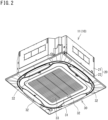
FIG. 2 is a perspective view of the indoor unit in the air conditioner according to the present disclosure. -
FIG. 3 is a perspective view of the indoor unit with a decorative panel being detached. -
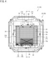
FIG. 4 is a bottom view of the indoor unit with the decorative panel being detached. -
FIG. 5 is a sectional view taken along line A-A indicated inFIG. 4 . -
FIG. 6 is a perspective view of the indoor unit with the decorative panel and a protecting member being detached. -
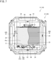
FIG. 7 is a bottom view of the indoor unit with the decorative panel and the protecting member being detached. -
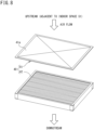
FIG. 8 is a perspective pattern view of a first filter and a second filter. -
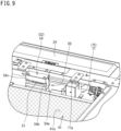
FIG. 9 is a partially enlarged perspective view of an ultraviolet ray irradiator and a limit switch. -
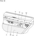
FIG. 10 is a partially enlarged perspective view of the ultraviolet ray irradiator with a blocking member (second member) being detached and the limit switch with a protecting cover being detached. -
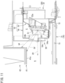
FIG. 11 is a schematic partial sectional view indicating an ultraviolet ray irradiating situation of the ultraviolet ray irradiator. -
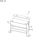
FIG. 12 is a perspective view of the blocking member (second member). -
FIG. 13 is a partially enlarged perspective view of an activated species generator. -
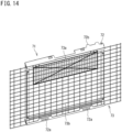
FIG. 14 is a perspective view of the protecting member (including a frame and a mesh body). -
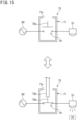
FIG. 15 is a schematic pattern view indicating behavior of the limit switch. -
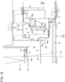
FIG. 16 is a schematic partial sectional view indicating an ultraviolet ray irradiating situation of the ultraviolet ray irradiator (in a case where the first filter is slantly disposed). -
FIG. 1 is a schematic configuration diagram of an air conditioner including an indoor unit according to the present disclosure.FIG. 1 depicts anair conditioner 10 configured to achieve a vapor compression refrigeration cycle to cool and heat an indoor space S1 provided in a building B. Theair conditioner 10 includes anindoor unit 11 exemplifying the indoor unit in the air conditioner according to the present disclosure. Theair conditioner 10 further includes anoutdoor unit 12 and arefrigerant pipe 13. Therefrigerant pipe 13 includes aliquid tube 13L and agas tube 13G. Theair conditioner 10 includes a refrigerant circuit constituted by connecting theindoor unit 11 and theoutdoor unit 12 via therefrigerant pipe 13. Theindoor unit 11 is disposed in the indoor space S1 whereas theoutdoor unit 12 is disposed in an outdoor space S2. The outdoor space S2 in this description also includes a space outside the indoor space S1 in the building B, while theoutdoor unit 12 according to the present embodiment is disposed outside the building B in the outdoor space S2. In theair conditioner 10 depicted inFIG. 1 , the singleindoor unit 11 is connected to the singleoutdoor unit 12. Alternatively, a plurality ofindoor units 11 may be connected to the singleoutdoor unit 12. The present embodiment exemplifies theair conditioner 10 configured to circulate a refrigerant in the refrigerant circuit to execute cooling operation and heating operation. The air conditioner including the indoor unit according to the present disclosure should not be limited to such a case, and may alternatively be configured to circulate cold water and warm water supplied from a heat source device to execute cooling operation and heating operation, and the indoor unit may be a so-called fan coil unit. -
FIG. 2 is a perspective view of the indoor unit in the air conditioner according to the present disclosure.FIG. 3 is a perspective view of the indoor unit with a decorative panel being detached.FIG. 4 is a bottom view of the indoor unit with the decorative panel being detached.FIG. 5 is a sectional view taken along line A-A indicated inFIG. 4 . As depicted inFIG. 1 andFIG. 2 , theindoor unit 11 is of a so-called cassette type, and includes acasing 20 and adecorative panel 30. - As depicted in
FIG. 3 andFIG. 4 , thecasing 20 has a substantially rectangular shape in a bottom view, and includes afirst casing 21 disposed in an upper portion and asecond casing 22 disposed in a lower portion. As depicted inFIG. 5 , thecasing 20 is provided therein with a space A accommodating anindoor fan 25, aheat exchanger 26, a collectingmember 40, anultraviolet ray irradiator 50, an activatedspecies generator 60, and the like, which will be described later. The space A also serves as an air flow path in thecasing 20. As depicted inFIG. 3 andFIG. 4 , thecasing 20 has a lower end portion provided with anintake port 23 positioned at a center portion of the rectangular shape, and fourair supply ports 24 surrounding theintake port 23. Theintake port 23 and theair supply ports 24 are openings provided at a lower end of the space A (seeFIG. 5 ). Theintake port 23 is provided with a protectingmember 71 to be described later. In theindoor unit 11 in a normal use state, thesecond casing 22 has a lower end portion covered with the decorative panel 30 (seeFIG. 2 ). - As depicted in
FIG. 2 , thedecorative panel 30 has a substantially rectangular shape in a bottom view, and includes anintake grill 31 disposed in a center portion of the rectangular shape, and four blow-outports 32 surrounding theintake grill 31. Theintake grill 31 is provided with anopening 33 having a slit shape. Theopening 33 is in communication with the space A (seeFIG. 5 ) via the intake port 23 (seeFIG. 3 ). The blow-outports 32 of thedecorative panel 30 are in communication with the space A (seeFIG. 5 ) via the air supply ports 24 (seeFIG. 3 ). Theindoor unit 11 sucks air in the indoor space S1 (seeFIG. 1 ) into thecasing 20 via theintake grill 31 and theintake port 23, and supplies the indoor space S1 with the air sucked into thecasing 20 via theair supply ports 24 and the blow-outports 32. - As depicted in
FIG. 5 , theindoor unit 11 includes theindoor fan 25 and theheat exchanger 26 accommodated in the casing 20 (the space A). Theindoor fan 25 is configured to circulate air in the indoor space S1. Theheat exchanger 26 constitutes part of the refrigerant circuit, and therefrigerant pipe 13 allows refrigerant circulation to and from theoutdoor unit 12. Theindoor unit 11 drives theindoor fan 25 to cause air (return air RA) in the indoor space S1 to be sucked in to thecasing 20 via the intake grill 31 (seeFIG. 2 ) and theintake port 23 and pass theheat exchanger 26, and cause cooled or heated air (supply air SA) to be supplied to the indoor space S1 via theair supply ports 24 and the blow-out ports 32 (seeFIG. 2 ). -
FIG. 6 is a perspective view of the indoor unit with the decorative panel and the protecting member being detached.FIG. 7 is a bottom view of the indoor unit with the decorative panel and the protecting member being detached.FIG. 8 is a perspective pattern view of the collecting member. As depicted inFIG. 6 andFIG. 7 , theindoor unit 11 includes the collectingmember 40 accommodated in thecasing 20. The collectingmember 40 is configured to collect dust contained in the air (return air RA) in the indoor space S1. As depicted inFIG. 8 , the collectingmember 40 includes afirst filter 41 as a first collectingmember 40, and asecond filter 42 as a second collectingmember 40. Thesecond filter 42 is configured to collect (finer) dust that cannot be perfectly collected by thefirst filter 41, and has finer mesh and higher collection efficiency (about 60% to 95%) in comparison to thefirst filter 41. In other words, thefirst filter 41 has coarser mesh in comparison to thesecond filter 42. The present embodiment exemplifies the case where the second collectingmember 40 is a filter. The second collecting member may alternatively be an electric dust collector. - As depicted in
FIG. 5 , thefirst filter 41 is disposed upstream of thesecond filter 42 in an air flow direction. Thefirst filter 41 has an upstream surface in the air flow direction, and the upstream surface will be referred to as afirst surface 41a in the following description. Thefirst surface 41a of thefirst filter 41 is a planar surface. The "planar surface" herein indicates that the surface has no unevenness (pleats) and has no shade when irradiated with oblique light with respect to the surface. The collectingmember 40 according to the present embodiment includes thefirst filter 41 and thesecond filter 42. The collecting member in the indoor unit according to the present disclosure may alternatively include only the first filter. - In the
indoor unit 11, the air (return air RA) sucked into thecasing 20 via the intake grill 31 (seeFIG. 2 ) and theintake port 23 passes the collectingmember 40. Thefirst filter 41 and thesecond filter 42 collect dust contained in the return air RA. In theindoor unit 11, dust generating injurious ingredients and odorous components adheres to thefirst surface 41a of thefirst filter 41. -
FIG. 9 is a partially enlarged perspective view of the ultraviolet ray irradiator and a limit switch.FIG. 10 is a partially enlarged perspective view of the ultraviolet ray irradiator with a blocking member (second member) being detached and the limit switch with a protecting cover being detached.FIG. 11 is a schematic partial sectional view indicating an ultraviolet ray irradiating situation of the ultraviolet ray irradiator.FIG. 12 is a perspective view of the blocking member (second member). As depicted inFIG. 5 to FIG. 7 ,FIG. 9 , andFIG. 10 , theindoor unit 11 includes theultraviolet ray irradiator 50. Theultraviolet ray irradiator 50 is configured to irradiate thefirst surface 41a of thefirst filter 41 with ultraviolet rays, and includes alight source 51 and a blockingmember 52. Thelight source 51 includes an LED device configured to generate ultraviolet rays when electrified. Thelight source 51 is equipped with a lens (not depicted) configured to diffuse ultraviolet rays generated by thelight source 51 substantially entirely on thefirst surface 41a. Thelight source 51 according to the present embodiment is fixed to thecasing 20 and irradiates thefirst surface 41a with ultraviolet rays from a fixed position. Alternatively, thelight source 51 may further include a displacement mechanism configured to displace thelight source 51 with respect to thecasing 20, and may be configured to irradiate thefirst surface 41a with ultraviolet rays while being displaced by the displacement mechanism. - As depicted in
FIG. 5 , theultraviolet ray irradiator 50 is disposed at a position deviated from an air flow from theintake port 23 toward the collectingmember 40. In other words, theultraviolet ray irradiator 50 is positioned not to be overlapped with theintake port 23 and the collectingmember 40 in a bottom view. If theultraviolet ray irradiator 50 is disposed in the air flow from theintake port 23 toward the collectingmember 40, theultraviolet ray irradiator 50 will increase air flow resistance. In theindoor unit 11 according to the present disclosure, theultraviolet ray irradiator 50 is disposed at a position deviated from the air flow from theintake port 23 toward the collectingmember 40 in order to inhibit increase in air flow resistance. - As depicted in
FIG. 6 ,FIG. 7 , andFIG. 9 toFIG. 11 , theultraviolet ray irradiator 50 includes the blockingmember 52. The blockingmember 52 is configured to restrict an irradiation range of ultraviolet rays from thelight source 51. - As depicted in
FIG. 9 to FIG. 11 , the blockingmember 52 is constituted by afirst member 53 supporting thelight source 51 from thecasing 20, and asecond member 54 covering thelight source 51 supported by thefirst member 53. The blockingmember 52 also serves as a member supporting thelight source 51 with respect to thecasing 20, and is screwed to thecasing 20. Thefirst member 53 and thesecond member 54 are each made of metal, and are combined to constitute the integrated blockingmember 52. The blockingmember 52 may alternatively be made of a material (e.g. resin) other than metal. - As depicted in
FIG. 11 , thefirst member 53 has anopening 53a provided for disposition of thelight source 51. Thelight source 51 fitted in theopening 53a is screwed to thefirst member 53. - As depicted in
FIG. 9 ,FIG. 11 , andFIG. 12 , thesecond member 54 includes abody 54a having a box shape. Thesecond member 54 and thefirst member 53 are used in combination with each other in a state where thefirst member 53 is disposed inside thebody 54a. The blockingmember 52, which is constituted by thefirst member 53 and thesecond member 54 in combination with each other, has a space X surrounded with thebody 54a and thefirst member 53. Theultraviolet ray irradiator 50 includes thelight source 51 disposed in the space X. - The
body 54a has anopening 54b. As depicted inFIG. 11 , thelight source 51 in the space X emits ultraviolet rays UV to be applied to the space A outside the blockingmember 52 via theopening 54b. In other words, the ultraviolet rays UV emitted from thelight source 51 in the space X contain ultraviolet rays UV that are directed to a point other than theopening 54b and are blocked by the blockingmember 52. Thebody 54a further includes aflange 54c surrounding theopening 54b. Theflange 54c accordingly blocks part of ultraviolet rays UV directed to the space A via theopening 54b. - The
body 54a and theflange 54c in the blockingmember 52 are disposed between thelight source 51 and theintake port 23, and blocks ultraviolet rays UV toward theintake port 23 in the ultraviolet rays UV from thelight source 51 toward the space A. In other words, theopening 54b and theflange 54c are disposed in theultraviolet ray irradiator 50 such that the blockingmember 52 does not block ultraviolet rays UV from thelight source 51 toward thefirst surface 41a of thefirst filter 41. In a case where thecasing 20 has an opening opened to face the indoor space S1 in addition to theintake port 23, thebody 54a and theflange 54c are preferably disposed also between the opening and thelight source 51. The blockingmember 52 is not limitedly configured as depicted in the present embodiment. In an exemplary case where thelight source 51 is not accommodated in the space X but is exposed in the space A, the blocking member may have a plate shape (without having the space X) and be disposed upstream of thelight source 51. In other words, the blocking member according to the present disclosure has only to be configured to inhibit irradiation of theindoor space S 1 with ultraviolet rays emitted from thelight source 51. - As depicted in
FIG. 6 ,FIG. 7 , andFIG. 13 , theindoor unit 11 includes the activatedspecies generator 60. The activatedspecies generator 60 is configured to supply air passing thecasing 20 with activated species, and includes acase 63 provided with anintake port 61 and adischarge port 62. The activatedspecies generator 60 has an electric discharger (not depicted) provided in thecase 63 and including a needle electrode and a counter electrode. When high voltage is applied to the electric discharger, the electric discharger generates streamer discharge as a type of plasma discharge. The activatedspecies generator 60 generates streamer discharge to generate activated species having high oxidative decomposition capacity. Examples of the activated species generated by the activatedspecies generator 60 include fast electrons, ions, hydroxylic radicals, and excited oxygen molecules, and the activated species decompose injurious ingredients and odorous components contained in the air and constituted by small organic molecules such as ammonium groups, aldehydes, or nitrogen oxides. - The activated
species generator 60 imports part of the air in thecasing 20 into thecase 63 via theintake port 61, and discharges, from thedischarge port 62 the activated species generated by the electric discharger along with the air. As depicted inFIG. 13 , theintake port 61 and thedischarge port 62 are disposed upstream of thefirst filter 41 in the air flow direction. The activatedspecies generator 60 thus generates activated species at a position upstream of thefirst filter 41. Theindoor unit 11 includes thelight source 51 and the activatedspecies generator 60, so as to clean (sterilize) thefirst surface 41a of thefirst filter 41 with use of ultraviolet rays, and clean the first surface also with use of activated species. Theindoor unit 11 accordingly has higher cleaning capacity in thecasing 20 in comparison to a conventional indoor unit including only an activated species generator. - As depicted in
FIG. 6 andFIG. 7 , in theindoor unit 11 according to the present disclosure, the activatedspecies generator 60 is positioned to face theultraviolet ray irradiator 50 with theintake port 23 and thefirst filter 41 interposed therebetween. Such a configuration inhibits unevenness in cleaning degree on thefirst surface 41a. - As depicted in
FIG. 4 , theindoor unit 11 includes aprotector 70 configured to protect a user from ultraviolet rays emitted from theultraviolet ray irradiator 50. Theprotector 70 includes the protectingmember 71 and alimit switch 75. -
FIG. 14 is a perspective view of the protecting member (including a frame and a mesh body).FIG. 3 to FIG. 5 depict the protectingmember 71 configured to inhibit entry of part of a human body (particularly a finger) into the irradiation range of ultraviolet rays in thecasing 20. The protectingmember 71 covers theintake port 23 to inhibit entry of a finger into the space A (seeFIG. 5 ) from theindoor space S 1 via theintake port 23. As depicted inFIG. 14 , the protectingmember 71 includes aframe 72 and amesh body 73. As depicted inFIG. 3 andFIG. 4 , the protectingmember 71 further includes astay 74. - As depicted in
FIG. 14 , theframe 72 is a member constituted by steel materials assembled into a substantially rectangular shape, and is provided withattachment holes 72a and aprotrusion 72b. Theprotrusion 72b projects toward an upper surface of the frame 72 (an upper side when the frame is attached to the casing 20). Themesh body 73 is attached to a lower surface of the frame 72 (a lower side when the frame is attached to the casing 20). - As depicted in
FIG. 3 andFIG. 4 , the lower end portion of thesecond casing 22 is provided with a pair of stays 74. The protectingmember 71 is attached to thecasing 20 such that the stays 74 are inserted to the attachment holes 72a and hang theframe 72. Among thecomponents 72 to 74 constituting the protectingmember 71, theframe 72 and themesh body 73 are detachably attached to thecasing 20. Theframe 72 and themesh body 73 are swingable with respect to thecasing 20 with a contact portion of theframe 72 and thestays 74 serving as a fulcrum. The protectingmember 71 in theindoor unit 11 is positioned to cover theintake port 23 while the indoor space S1 is air conditioned. The protectingmember 71 in theindoor unit 11 is positioned to be apart from theintake port 23 when air conditioning of the indoor space S1 is stopped and the interior of thecasing 20 is maintained. The protectingmember 71 is configured to be detachably attached to thecasing 20. - The
mesh body 73 is a member constituted by steel wires woven into a lattice shape, and includes afirst region 73a and asecond region 73b. Thefirst region 73a depicted inFIG. 3 ,FIG. 4 , andFIG. 14 is surrounded with a bold solid line. Thefirst region 73a is disposed adjacent to theultraviolet ray irradiator 50 in themesh body 73. Thesecond region 73b corresponds to a region other than thefirst region 73a in themesh body 73. Thesecond region 73b is disposed farther from theultraviolet ray irradiator 50 than thefirst region 73a. - If a finger of a user (part of a human body) is inserted to the
casing 20 from the protectingmember 71, the finger may be irradiated with ultraviolet rays emitted from theultraviolet ray irradiator 50 in thefirst region 73a. Even if the finger of the user (part of the human body) is inserted to thecasing 20 from the protectingmember 71, the finger cannot be irradiated with ultraviolet rays emitted from theultraviolet ray irradiator 50 in thesecond region 73b. Themesh body 73 in thefirst region 73a has a first mesh size M1, and themesh body 73 in thesecond region 73b has a second mesh size M2. The protectingmember 71 according to the present embodiment is provided with mesh (a lattice) having an oblong shape that has a short side having a size referred to as the "mesh size". - In the
protector 70, the first mesh size M1 in thefirst region 73a is smaller than the second mesh size M2 in thesecond region 73b. Specifically, thefirst region 73a according to the present embodiment includes steel wires having a wire diameter of 2 mm and aligned at a pitch of 9 mm on a short side, and has an opening of about 7 mm on the short side. That is, the first mesh size M1 in thefirst region 73a is sized not to allow insertion of a test finger having an outer diameter of ϕ8.5. It is thus impossible for a user to insert a finger in a gap of the mesh in thefirst region 73a. The protectingmember 71 in theindoor unit 11 can inhibit irradiation of a human body with ultraviolet rays emitted from theultraviolet ray irradiator 50. - Meanwhile, the
second region 73b according to the present embodiment includes steel wires having a wire diameter of 2 mm and aligned at a pitch of 13.5 mm on a short side, and has an opening of about 11.5 mm on the short side. That is, the second mesh size M2 in thesecond region 73b is sized to allow insertion of the test finger having the outer diameter of ϕ8.5. The protectingmember 71 in theindoor unit 11 is reduced in weight by limiting an area of thefirst region 73a. -
FIG. 15 is a schematic pattern view indicating behavior of the limit switch. As depicted inFIG. 9 andFIG. 10 , thelimit switch 75 includes aswitch body 76 and a protectingcover 77. As depicted inFIG. 6 ,FIG. 7 ,FIG. 9 , andFIG. 10 , thelimit switch 75 is disposed in thecasing 20. Thelimit switch 75 is configured to inhibit irradiation of a human body with ultraviolet rays when a user detaches the protectingmember 71 from thecasing 20. - As depicted in
FIG. 9 , the protectingcover 77 is provided with anopening 77a. In a state where the protectingmember 71 is attached at a predetermined position of thecasing 20, theprotrusion 72b (seeFIG. 14 ) of the protectingmember 71 is inserted to the protectingcover 77 via theopening 77a. - As depicted in
FIG. 10 , theswitch body 76 is disposed inside the protectingcover 77. Theswitch body 76 includes apressed part 76a. In a state where the protectingmember 71 is attached at the predetermined position of thecasing 20, theprotrusion 72b (seeFIG. 14 ) inserted to the protectingcover 77 via theopening 77a presses thepressed part 76a. - As depicted in
FIG. 15 , thelimit switch 75 is connected to apower source circuit 80 configured to supply thelight source 51 with electric power. Thelimit switch 75 enables supply of electric power from thepower source circuit 80 to thelight source 51 in a state where thepressed part 76a of theswitch body 76 is pressed (see a lower portion inFIG. 15 ). Thelight source 51 emits ultraviolet rays UV in this case. Thelimit switch 75 blocks supply of electric power from thepower source circuit 80 to thelight source 51 in another state where thepressed part 76a is not pressed (see an upper portion inFIG. 15 ). Thelight source 51 does not emit ultraviolet rays UV in this case. - In the
protector 70, thelimit switch 75 enables ultraviolet ray irradiation by thelight source 51 in the state where the protectingmember 71 is attached at the predetermined position of the casing 20 (see the lower portion inFIG. 15 ), and thelimit switch 75 disables ultraviolet ray irradiation by thelight source 51 in a state where the protectingmember 71 is detached from the casing 20 (see the upper portion inFIG. 15 ). In theindoor unit 11, thelimit switch 75 inhibits irradiation of a human body with ultraviolet rays emitted from theultraviolet ray irradiator 50 in his manner. -
FIG. 16 is a schematic partial sectional view indicating an ultraviolet ray irradiating situation of the ultraviolet ray irradiator (in a case where the first filter is slantly disposed). In theindoor unit 11 described above, thefirst filter 41 is disposed to have a posture with thefirst surface 41a having a normal line directed vertically downward (seeFIG. 11 ). Thefirst filter 41 may alternatively be disposed such that the normal line of thefirst surface 41a is slanted from a vertical direction. In theindoor unit 11 depicted inFIG. 16 , thefirst filter 41 is disposed such that a normal line L2 of thefirst surface 41a is slanted at an angle θ toward thelight source 51 with respect to a vertical line L1. In theindoor unit 11 depicted inFIG. 16 , thelight source 51 irradiates thefirst surface 41a with ultraviolet rays in this state. - The cleaning capacity for the
first filter 41 with use of ultraviolet rays can be evaluated by a product of irradiation intensity and irradiation time of the ultraviolet rays. In an exemplary case where the ultraviolet rays UV having irradiation intensity Y1 are applied to thefirst surface 41a at an incidence angle α, irradiation intensity Y2 of ultraviolet rays on thefirst surface 41a is obtained by multiplying the irradiation intensity Y1 by cosα (Y2 = Y1cosα). - As depicted in
FIG. 16 , in theindoor unit 11 according to the present disclosure, thelight source 51 irradiates thefirst surface 41a of thefirst filter 41 in the state where the normal line L2 of thefirst surface 41a is slanted from a vertically downward portion toward thelight source 51 at the angle θ. In comparison to a case where thefirst filter 41 is not slanted (when θ = 0°), the incidence angle α of the ultraviolet rays UV to thefirst surface 41a can approach 90 degrees in this configuration. The incidence angle α of the ultraviolet rays UV to thefirst surface 41a can thus be increased in comparison to a case where thelight source 51 is disposed at a position deviated from the air flow, for improvement of the irradiation intensity Y2 of ultraviolet rays to thefirst filter 41. Theindoor unit 11 depicted inFIG. 16 can thus secure sufficient irradiation intensity of ultraviolet rays emitted from thelight source 51 for cleaning of thefirst surface 41a, so as to reliably clean thefirst filter 41. Thefirst filter 41 may be provided while constantly slanted at the angle θ from thecasing 20, or may be configured to be slanted only upon emitting ultraviolet rays from thelight source 51 with use of a mechanism (not depicted). - The
air conditioner 10 is configured to start and stop operation in accordance with operation of a remote controller (not depicted) disposed in the indoor space S1 or the like. Upon operation start of theair conditioner 10, thelight source 51 in theindoor unit 11 irradiates thefirst surface 41a of thefirst filter 41 with ultraviolet rays for a predetermined time period. Thefirst filter 41 can thus be cleaned each time the air conditioner starts operation while a user is unconscious of ultraviolet ray irradiation timing. Alternatively, theindoor unit 11 may execute residual operation for the predetermined time period upon operation stop of theair conditioner 10, and thelight source 51 may irradiate thefirst surface 41a of thefirst filter 41 with ultraviolet rays during such residual operation. In this case, thefirst filter 41 can be cleaned upon operation stop while a user is unconscious of ultraviolet ray irradiation timing, to enable subsequent operation start with the interior of thecasing 20 being clean. - The
light source 51 adopted in theindoor unit 11 has a characteristic that irradiation intensity decreases as irradiation time increases. Theindoor unit 11 has a function of recording irradiation time of thelight source 51, and each ultraviolet ray irradiation time is increased in accordance with increase of the irradiation time. In this case, thefirst filter 41 can be reliably cleaned even if theindoor unit 11 is increased in total operation time and thelight source 51 is decreased in irradiation intensity. - The
indoor unit 11 may further restrict each irradiation time of thelight source 51. This achieves inhibiting thelight source 51 from ending its life before theindoor unit 11 ends its product life. Theultraviolet ray irradiator 50 can accordingly maintain a function of cleaning thefirst filter 41 until theindoor unit 11 ends its product life without replacement of thelight source 51. -
- (1) The
indoor unit 11 according to the embodiment described above is included in theair conditioner 10 configured to condition air in the indoor space S1, and theindoor unit 11 includes thecasing 20 provided with theintake port 23 opened downward toward the indoor space S1, theindoor fan 25 configured to suck the air in the indoor space S1 into thecasing 20 via theintake port 23, thefirst filter 41 configured to collect dust contained in the air sucked via theintake port 23, theultraviolet ray irradiator 50 configured to irradiate the upstream side of thefirst filter 41 in an air flow direction with ultraviolet rays, and the blockingmember 52 configured to block ultraviolet rays from theultraviolet ray irradiator 50 toward theintake port 23.
In theindoor unit 11 thus configured, the blockingmember 52 can inhibit irradiation of the indoor space S1 with the ultraviolet rays emitted from theultraviolet ray irradiator 50. It is accordingly possible to provide theindoor unit 11 having the function of cleaning thefirst filter 41 with use of ultraviolet rays, for higher cleaning capacity in thecasing 20 of theindoor unit 11. - (2) The
indoor unit 11 according to the above embodiment further includes the protectingmember 71 having a mesh shape and covering theintake port 23 at a position upstream of thefirst filter 41 in the air flow direction. The first mesh size M1 in thefirst region 73a positioned adjacent to thelight source 51 in the protectingmember 71 is smaller than the second mesh size M2 in thesecond region 73b positioned farther from thelight source 51 than thefirst region 73a in the protectingmember 71, and the first mesh size M1 is sized not to allow insertion of the test finger having the outer diameter of ϕ8.5.
This configuration can inhibit a user from inserting a finger to thecasing 20 in thefirst region 73a in the protectingmember 71. This accordingly achieves inhibiting irradiation of the finger of the user with the ultraviolet rays emitted from thelight source 51. - (3) In the
indoor unit 11 according to the above embodiment, the protectingmember 71 is detachably attached to thecasing 20, and there is further provided thelimit switch 75 configured to be turned ON and turned OFF to interlock with attachment and detachment of the protectingmember 71. Thelimit switch 75 in theindoor unit 11 enables ultraviolet ray irradiation by theultraviolet ray irradiator 50 in the case where the protectingmember 71 is attached to thecasing 20, and disables ultraviolet ray irradiation by theultraviolet ray irradiator 50 in the other case where the protectingmember 71 is detached from thecasing 20.
Such a configuration can inhibit irradiation of a user with the ultraviolet rays emitted from theultraviolet ray irradiator 50 when the user works with the protectingmember 71 being detached. - (4) In the
indoor unit 11 according to the above embodiment, thefirst filter 41 has an upstream surface in the air flow direction, and the upstream surface corresponds to thefirst surface 41a having the planar shape. In theindoor unit 11, thelight source 51 irradiates thefirst surface 41a with ultraviolet rays.
In this case, theultraviolet ray irradiator 50 irradiates thefirst surface 41a having the planar surface with ultraviolet rays so as to inhibit any portion irradiated with no ultraviolet rays in thefirst filter 41 upstream in the air flow direction. The ultraviolet rays emitted from theultraviolet ray irradiator 50 can thus reliably clean thefirst filter 41. - (5) The
indoor unit 11 according to the above embodiment further includes thesecond filter 42 configured to collect dust contained in the air sucked via theintake port 23 at a position downstream of thefirst filter 41 in the air flow direction. Thefirst filter 41 in theindoor unit 11 has coarser mesh in comparison to thesecond filter 42.
Provision of thesecond filter 42 in addition to thefirst filter 41 in this case achieves reliable collection of dust and the like contained in the air. - (6) In the
indoor unit 11 according to the above embodiment, theultraviolet ray irradiator 50 is disposed at a position deviated from the air flow from theintake port 23 to thefirst filter 41.
In this case, theultraviolet ray irradiator 50 can inhibit increase in air flow resistance of air flowing in thecasing 20. - (7) In the
indoor unit 11 according to the above embodiment, theultraviolet ray irradiator 50 irradiates thefirst filter 41 with ultraviolet rays in the state where the normal line L2 of thefirst surface 41a is slanted at the angle θ toward theultraviolet ray irradiator 50 from the vertical line L1.
This case achieves securing irradiation intensity of the ultraviolet rays applied to thefirst surface 41a from theultraviolet ray irradiator 50 in the configuration in which theultraviolet ray irradiator 50 is disposed at a position deviated from the air flow. The ultraviolet rays emitted from theultraviolet ray irradiator 50 can thus reliably clean thefirst filter 41. - (8) The
indoor unit 11 according to the above embodiment further includes the activatedspecies generator 60 configured to generate activated species at a position upstream of thefirst filter 41 in the air flow direction.
In this case, provision of thelight source 51 and the activatedspecies generator 60 leads to higher cleaning capacity in thecasing 20. - The present disclosure should not be limited to the above exemplification, but is intended to include any modification recited in the claims within meanings and a scope equivalent to those of the claims.
-
- 10
- air conditioner
- 11
- indoor unit
- 20
- casing
- 23
- intake port
- 25
- indoor fan (fan)
- 41
- first filter (first collecting member)
- 41a
- first surface
- 42
- second filter (second collecting member)
- 50
- ultraviolet ray irradiator
- 51
- light source
- 52
- blocking member
- 60
- activated species generator (generator)
- 71
- protecting member
- 73a
- first region
- 73b
- second region
- 75
- limit switch (switch)
- S1
- indoor space
- M1
- first mesh size
- M2
- second mesh size
Claims (8)
- An indoor unit (11) in an air conditioner (10) configured to condition air in an indoor space (S1), the indoor unit (11) comprising:a casing (20) provided with an intake port (23) opened downward toward the indoor space (S1);a fan (25) configured to suck air in the indoor space (S1) into the casing (20) via the intake port (23);a first collecting member (41) configured to collect dust contained in the air sucked via the intake port (23);a light source (51) configured to irradiate an upstream side of the first collecting member (41) in an air flow direction with ultraviolet rays; anda blocking member (52) configured to block ultraviolet rays from the light source (51) toward the intake port (23).
- The indoor unit (11) in the air conditioner (10) according to claim 1, the indoor unit further comprisinga protecting member (71) having a mesh shape and covering the intake port (23) at a position upstream of the first collecting member (41) in the air flow direction,wherein a first mesh size (M1) in a first region (73a) positioned adjacent to the light source (51) in the protecting member (71) is smaller than a second mesh size (M2) in a second region (73b) positioned farther from the light source (51) than the first region (73a) in the protecting member (71), andthe first mesh size (M1) is sized not to allow insertion of a test finger having an outer diameter of ϕ8.5.
- The indoor unit (11) in the air conditioner (10) according to claim 1 or 2, whereinthe protecting member (71) is detachably attached to the casing (20),the indoor unit further comprises a switch (75) configured to be turned ON and turned OFF to interlock with attachment and detachment of the protecting member (71),andthe switch (75)enables ultraviolet ray irradiation by the light source (51) in a case where the protecting member (71) is attached to the casing (20), and disables ultraviolet ray irradiation by the light source (51) in another case where the protecting member (71) is detached from the casing (20).
- The indoor unit (11) in the air conditioner (10) according to any one of claims 1 to 3, whereinthe first collecting member (41) has a first surface (41a) having a planar surface as an upstream surface in the air flow direction, andthe light source (51) irradiates the first surface (41a) with ultraviolet rays.
- The indoor unit (11) in the air conditioner (10) according to any one of claims 1 to 4, the indoor unit further comprisinga second collecting member (42) configured to collect dust contained in air sucked via the intake port (23) at a position downstream of the first collecting member (41) in the air flow direction,wherein each of the first collecting member (41) and the second collecting member (42) is a filter, andthe first collecting member (41) has coarser mesh in comparison to the second collecting member (42).
- The indoor unit (11) in the air conditioner (10) according to any one of claims 1 to 5, wherein the light source (51) is disposed at a position deviated from an air flow from the intake port (23) to the first collecting member (41).
- The indoor unit (11) in the air conditioner (10) according to claim 6, whereinthe first collecting member (41) has a first surface (41a) having a planar surface as an upstream surface in the air flow direction, andthe light source (51) irradiates the first collecting member (41) with ultraviolet rays in a state where the first surface (41a) has a normal line (L2) slanted from a vertically downward portion toward the light source (51).
- The indoor unit (11) in the air conditioner (10) according to any one of claims 1 to 7, the indoor unit further comprising a generator (60) configured to generate activated species at a position upstream of the first collecting member (41) in the air flow direction.
Applications Claiming Priority (2)
| Application Number | Priority Date | Filing Date | Title |
|---|---|---|---|
| JP2021136179A JP7260808B2 (en) | 2021-08-24 | 2021-08-24 | Indoor unit of air conditioner |
| PCT/JP2022/022282 WO2023026623A1 (en) | 2021-08-24 | 2022-06-01 | Indoor unit of air conditioning device |
Publications (3)
| Publication Number | Publication Date |
|---|---|
| EP4394266A1 true EP4394266A1 (en) | 2024-07-03 |
| EP4394266A4 EP4394266A4 (en) | 2025-01-01 |
| EP4394266B1 EP4394266B1 (en) | 2025-12-03 |
Family
ID=85321710
Family Applications (1)
| Application Number | Title | Priority Date | Filing Date |
|---|---|---|---|
| EP22860919.4A Active EP4394266B1 (en) | 2021-08-24 | 2022-06-01 | Indoor unit of air conditioning device |
Country Status (7)
| Country | Link |
|---|---|
| US (1) | US12276428B2 (en) |
| EP (1) | EP4394266B1 (en) |
| JP (1) | JP7260808B2 (en) |
| CN (1) | CN117795260B (en) |
| AU (2) | AU2022335810B2 (en) |
| ES (1) | ES3057776T3 (en) |
| WO (1) | WO2023026623A1 (en) |
Family Cites Families (23)
| Publication number | Priority date | Publication date | Assignee | Title |
|---|---|---|---|---|
| JPH09276629A (en) * | 1996-04-12 | 1997-10-28 | Daikin Ind Ltd | Multifunctional multilayer filter |
| US6911186B2 (en) * | 1998-11-05 | 2005-06-28 | Sharper Image Corporation | Electro-kinetic air transporter and conditioner device with enhanced housing configuration and enhanced anti-microorganism capability |
| US6589489B2 (en) * | 2001-03-30 | 2003-07-08 | L2B Environmental Systems Inc. | Air purifier |
| US20060057020A1 (en) * | 2002-10-21 | 2006-03-16 | Joseph Tufo | Cleaning of air |
| JP3852429B2 (en) | 2003-08-06 | 2006-11-29 | 株式会社日立製作所 | Air cleaner |
| JP2005351536A (en) | 2004-06-10 | 2005-12-22 | Matsushita Electric Ind Co Ltd | Air-conditioner |
| HK1063577A2 (en) * | 2004-06-23 | 2004-11-26 | John Manufacturing Ltd | Photoelectron air-purifying disinfecting and air conditioning machine |
| CN1789827A (en) * | 2004-12-13 | 2006-06-21 | 乐金电子(天津)电器有限公司 | Protection hood for wall-hanging indoor unit of split type air conditioner |
| CN103347544B (en) * | 2010-11-18 | 2016-01-13 | Oy霍尔顿集团有限公司 | Air cleaning facility method and system |
| US9222687B2 (en) * | 2012-02-03 | 2015-12-29 | Mestek, Inc. | Active chilled beam with sterilization means |
| WO2014115258A1 (en) * | 2013-01-23 | 2014-07-31 | 盛和工業株式会社 | Air purification device |
| US20170128613A1 (en) * | 2015-09-16 | 2017-05-11 | Michael Stewart | Method and system for cleaning air |
| EP3558850B1 (en) * | 2016-12-22 | 2022-06-29 | Maersk Container Industry A/S | Cooling machine, reefer container |
| JP7185392B2 (en) | 2017-08-10 | 2022-12-07 | ダイキン工業株式会社 | Indoor unit of air conditioner |
| WO2020039492A1 (en) * | 2018-08-21 | 2020-02-27 | 日立ジョンソンコントロールズ空調株式会社 | Indoor unit for air conditioner |
| CN209706260U (en) * | 2019-04-12 | 2019-11-29 | 赛多空气净化技术(廊坊)有限公司 | Air purifier with ultraviolet-sterilization lamp system UV protection device |
| CN111059632A (en) * | 2019-12-06 | 2020-04-24 | 珠海格力电器股份有限公司 | Indoor unit and air conditioner having the same |
| US20230073141A1 (en) * | 2020-02-14 | 2023-03-09 | Blueair Ab | Air purifier |
| US11499707B2 (en) * | 2020-04-13 | 2022-11-15 | Calyxpure, Inc. | Light fixture having a fan and ultraviolet sterilization functionality |
| US20210396408A1 (en) * | 2020-06-22 | 2021-12-23 | Carl Saieva | Anti-viral and antibacterial air filtration system |
| CN111811057A (en) * | 2020-06-23 | 2020-10-23 | 珠海格力电器股份有限公司 | Ultraviolet sterilization device, air conditioner and air conditioner sterilization control method |
| KR102956992B1 (en) * | 2020-06-25 | 2026-04-24 | 삼성전자주식회사 | Air cleaner |
| CN214415871U (en) * | 2020-12-09 | 2021-10-19 | 深圳市安拓浦科技有限公司 | Wall-mounted air purifier |
-
2021
- 2021-08-24 JP JP2021136179A patent/JP7260808B2/en active Active
-
2022
- 2022-06-01 CN CN202280054256.3A patent/CN117795260B/en active Active
- 2022-06-01 WO PCT/JP2022/022282 patent/WO2023026623A1/en not_active Ceased
- 2022-06-01 AU AU2022335810A patent/AU2022335810B2/en active Active
- 2022-06-01 ES ES22860919T patent/ES3057776T3/en active Active
- 2022-06-01 EP EP22860919.4A patent/EP4394266B1/en active Active
-
2024
- 2024-02-14 US US18/441,251 patent/US12276428B2/en active Active
- 2024-07-09 AU AU2024204735A patent/AU2024204735B2/en active Active
Also Published As
| Publication number | Publication date |
|---|---|
| ES3057776T3 (en) | 2026-03-04 |
| US20240183545A1 (en) | 2024-06-06 |
| JP2023030831A (en) | 2023-03-08 |
| AU2024204735B2 (en) | 2025-07-17 |
| JP7260808B2 (en) | 2023-04-19 |
| CN117795260A (en) | 2024-03-29 |
| AU2022335810A1 (en) | 2024-03-21 |
| EP4394266B1 (en) | 2025-12-03 |
| CN117795260B (en) | 2025-02-18 |
| EP4394266A4 (en) | 2025-01-01 |
| AU2024204735A1 (en) | 2024-08-01 |
| WO2023026623A1 (en) | 2023-03-02 |
| AU2022335810B2 (en) | 2024-08-01 |
| US12276428B2 (en) | 2025-04-15 |
Similar Documents
| Publication | Publication Date | Title |
|---|---|---|
| PT2033664E (en) | Sterilization method | |
| US20050175512A1 (en) | Electro-optical air sterilizer with ionizer | |
| KR20220000126A (en) | Air cleaner | |
| JP5371695B2 (en) | Air conditioner indoor unit | |
| CN117804022B (en) | Air Purifier | |
| KR100452028B1 (en) | Indoor unit for air conditioner | |
| US20060150819A1 (en) | Electro-optical air purifier with ionizer | |
| CN213931177U (en) | Double-air-inlet air conditioner | |
| EP4394266B1 (en) | Indoor unit of air conditioning device | |
| JP2004359231A (en) | Vehicular photoelectron air cleaner | |
| KR20100051469A (en) | Indoor unit of airconditioner | |
| JP6287822B2 (en) | Dust remover for air conditioner, air conditioner equipped with the dust remover, and vehicle equipped with the air conditioner | |
| JP7307356B2 (en) | air conditioner | |
| JP5677403B2 (en) | Dust remover for air conditioner, air conditioner equipped with the dust remover, and vehicle equipped with the air conditioner | |
| US11160896B1 (en) | Light blocking apparatus and air purifier | |
| US11779675B2 (en) | Air sterilization insert for heating, ventilation, and air conditioning (HVAC) systems | |
| GB2415627A (en) | Electro-optical air purifier | |
| RU2241492C2 (en) | Method for sterilizing air, instrument for producing ions and device for air-conditioning | |
| JP2025118445A (en) | air purifier | |
| CN213273111U (en) | Air curtain with ultraviolet lamp | |
| US20080101998A1 (en) | Air purification system and apparatus | |
| KR20100062668A (en) | Humidifier | |
| KR100758953B1 (en) | Indoor unit of air conditioner | |
| JP2022153929A (en) | air purifier | |
| JP4339104B2 (en) | Air conditioner |
Legal Events
| Date | Code | Title | Description |
|---|---|---|---|
| STAA | Information on the status of an ep patent application or granted ep patent |
Free format text: STATUS: THE INTERNATIONAL PUBLICATION HAS BEEN MADE |
|
| PUAI | Public reference made under article 153(3) epc to a published international application that has entered the european phase |
Free format text: ORIGINAL CODE: 0009012 |
|
| STAA | Information on the status of an ep patent application or granted ep patent |
Free format text: STATUS: REQUEST FOR EXAMINATION WAS MADE |
|
| 17P | Request for examination filed |
Effective date: 20240305 |
|
| AK | Designated contracting states |
Kind code of ref document: A1 Designated state(s): AL AT BE BG CH CY CZ DE DK EE ES FI FR GB GR HR HU IE IS IT LI LT LU LV MC MK MT NL NO PL PT RO RS SE SI SK SM TR |
|
| DAV | Request for validation of the european patent (deleted) | ||
| DAX | Request for extension of the european patent (deleted) | ||
| A4 | Supplementary search report drawn up and despatched |
Effective date: 20241129 |
|
| RIC1 | Information provided on ipc code assigned before grant |
Ipc: F24F 1/0076 20190101ALI20241125BHEP Ipc: F24F 1/0071 20190101ALI20241125BHEP Ipc: F24F 1/0011 20190101ALI20241125BHEP Ipc: F24F 8/22 20210101ALI20241125BHEP Ipc: F24F 8/108 20210101ALI20241125BHEP Ipc: F24F 1/0073 20190101AFI20241125BHEP |
|
| P01 | Opt-out of the competence of the unified patent court (upc) registered |
Free format text: CASE NUMBER: APP_1125/2025 Effective date: 20250108 |
|
| GRAP | Despatch of communication of intention to grant a patent |
Free format text: ORIGINAL CODE: EPIDOSNIGR1 |
|
| STAA | Information on the status of an ep patent application or granted ep patent |
Free format text: STATUS: GRANT OF PATENT IS INTENDED |
|
| RIC1 | Information provided on ipc code assigned before grant |
Ipc: F24F 1/0073 20190101AFI20250804BHEP Ipc: F24F 8/108 20210101ALI20250804BHEP Ipc: F24F 8/22 20210101ALI20250804BHEP Ipc: F24F 1/0011 20190101ALI20250804BHEP Ipc: F24F 1/0071 20190101ALI20250804BHEP Ipc: F24F 1/0076 20190101ALI20250804BHEP |
|
| INTG | Intention to grant announced |
Effective date: 20250814 |
|
| GRAS | Grant fee paid |
Free format text: ORIGINAL CODE: EPIDOSNIGR3 |
|
| GRAA | (expected) grant |
Free format text: ORIGINAL CODE: 0009210 |
|
| STAA | Information on the status of an ep patent application or granted ep patent |
Free format text: STATUS: THE PATENT HAS BEEN GRANTED |
|
| AK | Designated contracting states |
Kind code of ref document: B1 Designated state(s): AL AT BE BG CH CY CZ DE DK EE ES FI FR GB GR HR HU IE IS IT LI LT LU LV MC MK MT NL NO PL PT RO RS SE SI SK SM TR |
|
| REG | Reference to a national code |
Ref country code: CH Ref legal event code: F10 Free format text: ST27 STATUS EVENT CODE: U-0-0-F10-F00 (AS PROVIDED BY THE NATIONAL OFFICE) Effective date: 20251203 Ref country code: GB Ref legal event code: FG4D |
|
| REG | Reference to a national code |
Ref country code: DE Ref legal event code: R096 Ref document number: 602022026327 Country of ref document: DE |
|
| REG | Reference to a national code |
Ref country code: IE Ref legal event code: FG4D |
|
| REG | Reference to a national code |
Ref country code: ES Ref legal event code: FG2A Ref document number: 3057776 Country of ref document: ES Kind code of ref document: T3 Effective date: 20260304 |
|
| REG | Reference to a national code |
Ref country code: NL Ref legal event code: MP Effective date: 20251203 |
|
| REG | Reference to a national code |
Ref country code: LT Ref legal event code: MG9D |
|
| PG25 | Lapsed in a contracting state [announced via postgrant information from national office to epo] |
Ref country code: NO Free format text: LAPSE BECAUSE OF FAILURE TO SUBMIT A TRANSLATION OF THE DESCRIPTION OR TO PAY THE FEE WITHIN THE PRESCRIBED TIME-LIMIT Effective date: 20260303 |
|
| PG25 | Lapsed in a contracting state [announced via postgrant information from national office to epo] |
Ref country code: FI Free format text: LAPSE BECAUSE OF FAILURE TO SUBMIT A TRANSLATION OF THE DESCRIPTION OR TO PAY THE FEE WITHIN THE PRESCRIBED TIME-LIMIT Effective date: 20251203 Ref country code: HR Free format text: LAPSE BECAUSE OF FAILURE TO SUBMIT A TRANSLATION OF THE DESCRIPTION OR TO PAY THE FEE WITHIN THE PRESCRIBED TIME-LIMIT Effective date: 20251203 |
|
| PG25 | Lapsed in a contracting state [announced via postgrant information from national office to epo] |
Ref country code: RS Free format text: LAPSE BECAUSE OF FAILURE TO SUBMIT A TRANSLATION OF THE DESCRIPTION OR TO PAY THE FEE WITHIN THE PRESCRIBED TIME-LIMIT Effective date: 20260303 |
|
| PG25 | Lapsed in a contracting state [announced via postgrant information from national office to epo] |
Ref country code: PL Free format text: LAPSE BECAUSE OF FAILURE TO SUBMIT A TRANSLATION OF THE DESCRIPTION OR TO PAY THE FEE WITHIN THE PRESCRIBED TIME-LIMIT Effective date: 20251203 |
|
| PG25 | Lapsed in a contracting state [announced via postgrant information from national office to epo] |
Ref country code: LV Free format text: LAPSE BECAUSE OF FAILURE TO SUBMIT A TRANSLATION OF THE DESCRIPTION OR TO PAY THE FEE WITHIN THE PRESCRIBED TIME-LIMIT Effective date: 20251203 |
|
| PG25 | Lapsed in a contracting state [announced via postgrant information from national office to epo] |
Ref country code: BG Free format text: LAPSE BECAUSE OF FAILURE TO SUBMIT A TRANSLATION OF THE DESCRIPTION OR TO PAY THE FEE WITHIN THE PRESCRIBED TIME-LIMIT Effective date: 20251203 |
|
| REG | Reference to a national code |
Ref country code: AT Ref legal event code: MK05 Ref document number: 1863976 Country of ref document: AT Kind code of ref document: T Effective date: 20251203 |
|
| PG25 | Lapsed in a contracting state [announced via postgrant information from national office to epo] |
Ref country code: NL Free format text: LAPSE BECAUSE OF FAILURE TO SUBMIT A TRANSLATION OF THE DESCRIPTION OR TO PAY THE FEE WITHIN THE PRESCRIBED TIME-LIMIT Effective date: 20251203 |
|
| PG25 | Lapsed in a contracting state [announced via postgrant information from national office to epo] |
Ref country code: LT Free format text: LAPSE BECAUSE OF FAILURE TO SUBMIT A TRANSLATION OF THE DESCRIPTION OR TO PAY THE FEE WITHIN THE PRESCRIBED TIME-LIMIT Effective date: 20251203 |
|
| PG25 | Lapsed in a contracting state [announced via postgrant information from national office to epo] |
Ref country code: SM Free format text: LAPSE BECAUSE OF FAILURE TO SUBMIT A TRANSLATION OF THE DESCRIPTION OR TO PAY THE FEE WITHIN THE PRESCRIBED TIME-LIMIT Effective date: 20251203 |
|
| PGFP | Annual fee paid to national office [announced via postgrant information from national office to epo] |
Ref country code: GB Payment date: 20260626 Year of fee payment: 5 |
|
| PGFP | Annual fee paid to national office [announced via postgrant information from national office to epo] |
Ref country code: IT Payment date: 20260623 Year of fee payment: 5 |
|
| PGFP | Annual fee paid to national office [announced via postgrant information from national office to epo] |
Ref country code: DE Payment date: 20260622 Year of fee payment: 5 |
|
| PG25 | Lapsed in a contracting state [announced via postgrant information from national office to epo] |
Ref country code: AT Free format text: LAPSE BECAUSE OF FAILURE TO SUBMIT A TRANSLATION OF THE DESCRIPTION OR TO PAY THE FEE WITHIN THE PRESCRIBED TIME-LIMIT Effective date: 20251203 |
|
| PG25 | Lapsed in a contracting state [announced via postgrant information from national office to epo] |
Ref country code: EE Free format text: LAPSE BECAUSE OF FAILURE TO SUBMIT A TRANSLATION OF THE DESCRIPTION OR TO PAY THE FEE WITHIN THE PRESCRIBED TIME-LIMIT Effective date: 20251203 |
|
| PG25 | Lapsed in a contracting state [announced via postgrant information from national office to epo] |
Ref country code: IS Free format text: LAPSE BECAUSE OF FAILURE TO SUBMIT A TRANSLATION OF THE DESCRIPTION OR TO PAY THE FEE WITHIN THE PRESCRIBED TIME-LIMIT Effective date: 20260403 Ref country code: PT Free format text: LAPSE BECAUSE OF FAILURE TO SUBMIT A TRANSLATION OF THE DESCRIPTION OR TO PAY THE FEE WITHIN THE PRESCRIBED TIME-LIMIT Effective date: 20260406 |
|
| PG25 | Lapsed in a contracting state [announced via postgrant information from national office to epo] |
Ref country code: CZ Free format text: LAPSE BECAUSE OF FAILURE TO SUBMIT A TRANSLATION OF THE DESCRIPTION OR TO PAY THE FEE WITHIN THE PRESCRIBED TIME-LIMIT Effective date: 20251203 |
|
| PGFP | Annual fee paid to national office [announced via postgrant information from national office to epo] |
Ref country code: FR Payment date: 20260626 Year of fee payment: 5 |
|
| PG25 | Lapsed in a contracting state [announced via postgrant information from national office to epo] |
Ref country code: SK Free format text: LAPSE BECAUSE OF FAILURE TO SUBMIT A TRANSLATION OF THE DESCRIPTION OR TO PAY THE FEE WITHIN THE PRESCRIBED TIME-LIMIT Effective date: 20251203 |
|
| PG25 | Lapsed in a contracting state [announced via postgrant information from national office to epo] |
Ref country code: SE Free format text: LAPSE BECAUSE OF FAILURE TO SUBMIT A TRANSLATION OF THE DESCRIPTION OR TO PAY THE FEE WITHIN THE PRESCRIBED TIME-LIMIT Effective date: 20251203 |