EP4394259A1 - A steam oven - Google Patents
A steam oven Download PDFInfo
- Publication number
- EP4394259A1 EP4394259A1 EP23213004.7A EP23213004A EP4394259A1 EP 4394259 A1 EP4394259 A1 EP 4394259A1 EP 23213004 A EP23213004 A EP 23213004A EP 4394259 A1 EP4394259 A1 EP 4394259A1
- Authority
- EP
- European Patent Office
- Prior art keywords
- water
- oven
- pipe
- container
- piezoelectric material
- Prior art date
- Legal status (The legal status is an assumption and is not a legal conclusion. Google has not performed a legal analysis and makes no representation as to the accuracy of the status listed.)
- Granted
Links
Images


Classifications
-
- F—MECHANICAL ENGINEERING; LIGHTING; HEATING; WEAPONS; BLASTING
- F24—HEATING; RANGES; VENTILATING
- F24C—DOMESTIC STOVES OR RANGES ; DETAILS OF DOMESTIC STOVES OR RANGES, OF GENERAL APPLICATION
- F24C15/00—Details
- F24C15/32—Arrangements of ducts for hot gases, e.g. in or around baking ovens
- F24C15/322—Arrangements of ducts for hot gases, e.g. in or around baking ovens with forced circulation
- F24C15/327—Arrangements of ducts for hot gases, e.g. in or around baking ovens with forced circulation with air moisturising
-
- F—MECHANICAL ENGINEERING; LIGHTING; HEATING; WEAPONS; BLASTING
- F24—HEATING; RANGES; VENTILATING
- F24C—DOMESTIC STOVES OR RANGES ; DETAILS OF DOMESTIC STOVES OR RANGES, OF GENERAL APPLICATION
- F24C15/00—Details
- F24C15/003—Details moisturising of air
Definitions
- the present invention relates to a steam oven which can perform a humidification function.
- Ovens with humidification function for the cooking environment further comprise a humidification device which injects moisture into the cooking chamber.
- the ovens with humidification function better preserve the organoleptic properties of foodstuffs, while keeping the foodstuffs in its own juices, thus ensuring that the foodstuffs are cooked so as to be soft and delicious. Moreover, the weight loss caused by liquid leaks of foodstuffs, which is an important issue during cooking, is eliminated.
- the piezoelectric materials are typically used in the field of ambient humidification and air conditioning, and crack and lose their function at temperatures above 50 °C. In the state of the art, there are serious problems in the adaptation of said materials to the ovens. One of the biggest problems encountered is the risk of the ceramic and the piezoelectric material being subject to impacts and damage during the installation of the piezoelectric material by the operator.
- the oven comprises an air separation receptacle having a first arm which is connected to the first pipe and to which the water coming from the first pipe is transferred, a second arm through which the air in the water is discharged, a moving mechanism which is positioned in the second arm and which prevents the water from leaving the second arm during the discharge of the air, and a base receptacle wherein the water coming from the first pipe is collected.
- the oven comprises an air separation receptacle which is manufactured from silicone material.
- the oven comprises a second pipe having at least three arms comprising at least one base receptacle connection end connected to the base receptacle, at least one container connection end providing connection to the container and a body connection end connected to the body.
- the oven has a container comprising a protective piece comprising a housing in the center thereof large enough to receive and fix the piezoelectric material and a first gap which is provided in the housing and which allows the passage of the water steam; the container further comprising a sealing member comprising a first surface which is joined by a connection member to the surface of the protective piece whereon the piezoelectric material is placed, a connection portion which enables the same to be joined with the second pipe on the second surface which does not contact the protective piece and a second gap which is centered on the connection portion and which enables the coming water to pass to the piezoelectric material.
- the oven comprises a container comprising a lid increasing the heat protection and having an inner surface wherein the protective piece is placed and fixed, a third gap which is provided on the inner surface and which provides the passage of the water steam, and an outer surface with which the distance adjustment means is joined.
- a piston or air release valve is used as the moving mechanism (6.3).
- the protective piece (9) is square-shaped, and the housing (9.1) provided in the center of the protective piece (9) and wherein the piezoelectric material (10) is placed and fixed has a circular structure.
- Said sealing member (11) is exactly the same size as the protective piece (9). Said two components are fixed to each other by means of a connection member, and thus the water coming from the second pipe (7) can reach the piezoelectric material (10) without leaking and is delivered to the atomizer without leaking.
- the container (8) comprises a piezoelectric material (10); a protective piece (9) comprising a housing (9.1) in the center thereof large enough to receive and fix the piezoelectric material (10) and a first gap (9.2) which is provided in the housing (9.1) and which allows the passage of the water steam; a distance adjustment means (13) which enables the distance of the container (8) to the interior of the oven (1) to be adjusted and which comprises a fourth gap (13.1) providing the passage of the water steam; a lid (12) increasing the heat protection and comprising an inner surface (12.1) wherein the protective piece (12.1) is placed and fixed, a third gap (12.3) which is provided on the inner surface (12.1) and which provides the passage of the water steam, and an outer surface (12.2) with which the distance adjustment means (13) is joined; and a sealing member (11) comprising a first surface (11.1) which is joined by a connection member to the surface of the protective piece (9) whereon the piezoelectric material (10) is placed, a connection portion (11.3)
- the protective piece (9) has a certain thickness and circular structure.
- the inner surface (12.1) of the lid (12) wherein the protective piece (9) is placed and the inner walls thereof have a thickness and a circular structure which surrounds said circular protective piece (9) with a certain thickness.
Landscapes
- Engineering & Computer Science (AREA)
- Chemical & Material Sciences (AREA)
- Combustion & Propulsion (AREA)
- Mechanical Engineering (AREA)
- General Engineering & Computer Science (AREA)
- Cookers (AREA)
Abstract
Description
- The present invention relates to a steam oven which can perform a humidification function.
- Ovens with humidification function for the cooking environment further comprise a humidification device which injects moisture into the cooking chamber. The ovens with humidification function better preserve the organoleptic properties of foodstuffs, while keeping the foodstuffs in its own juices, thus ensuring that the foodstuffs are cooked so as to be soft and delicious. Moreover, the weight loss caused by liquid leaks of foodstuffs, which is an important issue during cooking, is eliminated.
- In the state of the art, it is known that for steam cookers which perform this function, the water in a water source is heated to generate steam by means of an electric heater. This water steam is then delivered to a cooking chamber. Here, the water is evaporated and the resulting water steam is delivered to the cooking chamber. Traditional steam oven systems, wherein the steam is generated by heating the water with electric resistance, are replaced by the steam generation technique with piezoelectric material. The characteristic of piezoelectric materials used to support this function in the ovens is to have the ability to change the electric field or electric potential of the material as a result of the mechanical pressure applied to certain materials.
- The piezoelectric materials are typically used in the field of ambient humidification and air conditioning, and crack and lose their function at temperatures above 50 °C. In the state of the art, there are serious problems in the adaptation of said materials to the ovens. One of the biggest problems encountered is the risk of the ceramic and the piezoelectric material being subject to impacts and damage during the installation of the piezoelectric material by the operator.
- Another problem encountered in the state of the art steam ovens is that as a result of the water flowing towards the piezoelectric material at high speed and the piezoelectric material being exposed to excessive water, the operation of the system is adversely affected in the delivery of the water into the oven.
- One of the problems encountered in said steam ovens is that as a result of the air compression in the chambers which receive the water while the water is drawn into the piezoelectric material, the water cannot be delivered to the piezoelectric material with the appropriate pressure and the steam generation function in the steam ovens cannot be performed. In the steam ovens, the water should directly contact the piezoelectric material in order to provide humidity in the oven. An air gap forms in the silicone pipes coming from the water tank to the piezoelectric material and since water cannot reach the piezoelectric material due to pressure, the piezoelectric material cannot generate water crystals when attached to the oven.
- Given the problems encountered in the state of the art, there is a need for a steam oven structure which can generate steam in the steam ovens using 100 percent piezoelectric material and eliminate the difficulties encountered in the adaptation of said material to the oven.
- The aim of the present invention is the realization of an oven structure which prevents the piezoelectric material used for ambient humidification and air conditioning in the steam ovens from losing its function at high oven temperatures and which enables the same to be adapted to the oven.
- Another aim of the present invention is the elimination of the risk of the ceramic and the piezoelectric material being subject to impacts during the installation of the piezoelectric material by the operator.
- Another aim of the present invention is the elimination of safety sensors due to the use of electric resistance water heaters, water level sensors and resistance by means of a structure which provides the use of piezoelectric material in the steam ovens.
- Another aim of the present invention is the realization of an oven structure which eliminates the air compression problem encountered during the delivery of the water to the piezoelectric material in the steam ovens.
- Another aim of the present invention is the realization of an oven structure which eliminates chronic problems such as double phase flow and condensation and the traces of lime in the oven, which are encountered due to the use of electric resistance water heaters for humidification in the state of the art.
- In an embodiment of the present invention, the oven comprises a body wherein the foodstuffs to be cooked are placed; a casing which surrounds the body; a water tank which is disposed between the casing and the body and which is filled with water; a first pipe which delivers the water coming from the water tank; an air separation receptacle wherein the air pocket in the water coming from the first pipe is separated; a second pipe which delivers the water in the air separation receptacle into the oven; and a container which provides protection and sealing and wherein the piezoelectric material enabling the water coming from the second pipe to be delivered into the oven as water steam is positioned.
- In an embodiment of the present invention, the oven comprises an air separation receptacle having a first arm which is connected to the first pipe and to which the water coming from the first pipe is transferred, a second arm through which the air in the water is discharged, a moving mechanism which is positioned in the second arm and which prevents the water from leaving the second arm during the discharge of the air, and a base receptacle wherein the water coming from the first pipe is collected.
- In an embodiment of the present invention, the oven comprises an air separation receptacle which is manufactured from silicone material.
- In an embodiment of the present invention, the oven comprises a second pipe having at least three arms comprising at least one base receptacle connection end connected to the base receptacle, at least one container connection end providing connection to the container and a body connection end connected to the body.
- In an embodiment of the present invention, the oven has a container comprising a protective piece comprising a housing in the center thereof large enough to receive and fix the piezoelectric material and a first gap which is provided in the housing and which allows the passage of the water steam; the container further comprising a sealing member comprising a first surface which is joined by a connection member to the surface of the protective piece whereon the piezoelectric material is placed, a connection portion which enables the same to be joined with the second pipe on the second surface which does not contact the protective piece and a second gap which is centered on the connection portion and which enables the coming water to pass to the piezoelectric material.
- In an embodiment of the present invention, the oven comprises a container which can be positioned at any point on the casing so as to ensure the connection thereof with the second pipe.
- In an embodiment of the present invention, the oven comprises a container wherein the piezoelectric material is positioned so as to remain between the protective piece and the sealing member.
- In an embodiment of the present invention, the oven comprises a container comprising a lid increasing the heat protection and having an inner surface wherein the protective piece is placed and fixed, a third gap which is provided on the inner surface and which provides the passage of the water steam, and an outer surface with which the distance adjustment means is joined.
- In an embodiment of the present invention, the oven comprises a container comprising a distance adjustment means which enables the distance of the container to the interior of the oven to be adjusted, which comprises a fourth gap providing the passage of the water steam and which is joined with the outer surface of the lid.
- In an embodiment of the present invention, the oven comprises a container comprising at least one capsule which is positioned between the sealing member and the second pipe, with one end placed in the connection portion and the other end placed in the container connection end.
- An oven realized in order to attain the aim of the present invention is illustrated in the attached figures, where:
-
Figure 1 : is the top perspective view of the components providing the delivery of the water in the steam ovens. -
Figure 2 : is the front perspective view of the air separation receptacle in the steam oven. -
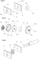
Figure 3 : is the view of the piezoelectric material and the container wherein the same is positioned in the steam oven. -
Figure 4 : is the exploded view of the container wherein the piezoelectric material is positioned in the steam oven in an embodiment of the present invention. -
Figure 5 : is the exploded view of the container wherein the piezoelectric material is positioned in the steam oven in another embodiment of the present invention. -
Figure 6 : is the exploded view of the container wherein the piezoelectric material is positioned in the steam oven in another embodiment of the present invention. - The following numerals are referred to in the description of the present invention:
- 1. Oven
- 2. Body
- 3. Casing
- 4. Water tank
- 5. First pipe
- 6. Air separation receptacle
- 6.1 First arm
- 6.2 Second arm
- 6.3 Moving mechanism
- 6.4 Base receptacle
- 7. Second pipe
- 7.1 Base receptacle connection end
- 7.2 Container connection end
- 7.3 Body connection end
- 8. Container
- 9. Protective piece
- 9.1 Housing
- 9.2 First gap
- 10. Piezoelectric material
- 11. Sealing member
- 11.1 First surface
- 11.2 Second surface
- 11.3 Connection portion
- 11.4 Second gap
- 12. Lid
- 12.1 Inner surface
- 12.2 Outer surface
- 12.3 Third gap
- 13. Distance adjustment means
13.1 Fourth gap - 14. Capsule
- The oven (1) of the present invention comprises a body (2) wherein the foodstuffs to be cooked are placed; a casing (3) which surrounds the body (2); a water tank (4) which is disposed between the casing (3) and the body (2) and which is filled with water; a first pipe (5) which delivers the water coming from the water tank (4); an air separation receptacle (6) wherein the air pocket in the water coming from the first pipe (5) is separated; a second pipe (7) which delivers the water in the air separation receptacle (6) into the oven (1); and a container (8) which provides protection and sealing and wherein the piezoelectric material (10) enabling the water coming from the second pipe (7) to be delivered into the oven (1) as water steam is positioned.
- In an embodiment of the present invention, the air separation receptacle (6) comprises a first arm (6.1) which is connected to the first pipe (5) and to which the water coming from the first pipe (5) is transferred, a second arm (6.2) through which the air in the water is discharged, a moving mechanism (6.3) which is positioned in the second arm (6.2) and which prevents the water from leaving the second arm (6.2) during the discharge of the air, and a base receptacle (6.4) wherein the water coming from the first pipe (5) is collected.
- In an embodiment of the present invention, a piston or air release valve is used as the moving mechanism (6.3).
- In an embodiment of the present invention, the water coming from the water tank (4) flows through the first pipe (5) and enters the air separation receptacle (6). While the incoming water flows along the first arm (6.1), the air remaining therein is discharged by means of the second arm (6.2). Thus, by ensuring that the air pocket which may occur in the second pipe (7) during the delivery of the water from the air separation receptacle (6) to the piezoelectric material (10) is discharged, the water is enabled to be delivered to the piezoelectric material (10) at an ideal pressure and the piezoelectric material (10) is enabled to generate water crystals for the oven (1). The moving mechanism (6.3) is placed for safety purposes to prevent the water from leaving the second arm (6.2). When the water collected in the base receptacle (6.4) reaches a certain level h, the water starts to flow into the second pipe (7).
- In an embodiment of the present invention, the air separation receptacle (6) is manufactured from silicone material.
- In an embodiment of the present invention, after the flow of the water collected in the base receptacle (6.4) starts, the water reaches the container (8) through the second pipe (7). The second pipe (7) is a pipe having at least three arms comprising at least one base receptacle connection end (7.1) connected to the base receptacle (6.4), at least one container connection end (7.2) providing connection to the container (8) and a body connection end (7.3) connected to the body (2).
- In an embodiment of the present invention, the piezoelectric material (10), which contacts the water to be converted to moisture, expands and shrinks in response to a potential difference applied to the piezoelectric crystal, and thus applies vibration to the water in a high-frequency ultrasonic range. The piezoelectric material (10) is arranged and configured so as to transmit its oscillatory voltages to the water in the atomization member as mechanical pulses. The atomizer is positioned directly on the casing (3) of the oven (1) such that the water crystals are transferred into the oven (1) without loss and the interior of the oven (1) is protected from high heat.
- In an embodiment of the present invention, the container (8) can be positioned at any point on the casing (3) so as to ensure the connection thereof with the second pipe (7).
- In an embodiment of the present invention, the container (8) comprises a piezoelectric material (10); a protective piece (9) comprising a housing (9.1) in the center thereof large enough to receive and fix the piezoelectric material (10) and a first gap (9.2) which is provided in the housing (9.1) and which allows the passage of the water steam; and a sealing member (11) comprising a first surface (11.1) which is joined by a connection member to the surface of the protective piece (9) whereon the piezoelectric material (10) is placed, a connection portion (11.3) which enables the same to be joined with the second pipe (7) on the second surface (11.2) which does not contact the protective piece (9) and a second gap (11.4) which is centered on the connection portion (11.3) and which enables the coming water to pass to the piezoelectric material (10). In an embodiment of the present invention, the piezoelectric material (10) is positioned so as to remain between the protective piece (9) and the sealing member (11). By means of said container (8), the piezoelectric material (10) is prevented from overheating and the sealing of the system is ensured.
- In an embodiment of the present invention, in order to ensure that the water coming from the second pipe (7) is converted into water steam by means of the piezoelectric material (10) and is then delivered into the oven (1), the second gap (11.4) on the sealing member (11) and the first gap (9.2) on the protective piece (9) are positioned such that the centers thereof are aligned so as to form a plane.
- In an embodiment of the present invention, the protective piece (9) is manufactured from silicone material.
- In an embodiment of the present invention, the protective piece (9) is square-shaped, and the housing (9.1) provided in the center of the protective piece (9) and wherein the piezoelectric material (10) is placed and fixed has a circular structure. Said sealing member (11) is exactly the same size as the protective piece (9). Said two components are fixed to each other by means of a connection member, and thus the water coming from the second pipe (7) can reach the piezoelectric material (10) without leaking and is delivered to the atomizer without leaking.
- In another embodiment of the present invention, the container (8) comprises a piezoelectric material (10); a protective piece (9) comprising a housing (9.1) in the center thereof large enough to receive and fix the piezoelectric material (10) and a first gap (9.2) which is provided in the housing (9.1) and which allows the passage of the water steam; a distance adjustment means (13) which enables the distance of the container (8) to the interior of the oven (1) to be adjusted and which comprises a fourth gap (13.1) providing the passage of the water steam; a lid (12) increasing the heat protection and comprising an inner surface (12.1) wherein the protective piece (12.1) is placed and fixed, a third gap (12.3) which is provided on the inner surface (12.1) and which provides the passage of the water steam, and an outer surface (12.2) with which the distance adjustment means (13) is joined; and a sealing member (11) comprising a first surface (11.1) which is joined by a connection member to the surface of the protective piece (9) whereon the piezoelectric material (10) is placed, a connection portion (11.3) which enables the same to be joined with the second pipe (7) on the second surface (11.2) which does not contact the protective piece (9) and a second gap (11.4) which is centered on the connection portion (11.3) and which enables the coming water to pass to the piezoelectric material (10).
- In another embodiment of the present invention, the protective piece (9) has a certain thickness and circular structure. In said embodiment of the present invention, the inner surface (12.1) of the lid (12) wherein the protective piece (9) is placed and the inner walls thereof have a thickness and a circular structure which surrounds said circular protective piece (9) with a certain thickness.
- In another embodiment of the present invention, in order to ensure that the water coming from the second pipe (7) is converted into water steam by means of the piezoelectric material (10) and is then delivered into the oven (1), the second gap (11.4) on the sealing member (11), the first gap (9.2) on the protective piece (9), the third gap (12.3) on the lid (12) and the fourth gap (13.1) on the distance adjustment means (13) are positioned such that the centers thereof are aligned so as to form a plane.
- In an embodiment of the present invention, the container (8) further comprises at least one capsule (14) which is positioned between the sealing member (11) and the second pipe (7), with one end placed in the connection portion (11.3) and the other end placed in the container connection end (7.2). Thus, the proper contact to the piezoelectric material (10) and sealing of water is ensured.
Claims (12)
- An oven (1) comprising a body (2) wherein the foodstuffs to be cooked are placed; a casing (3) surrounding the body (2); a water tank (4) disposed between the casing (3) and the body (2) and filled with water; and a first pipe (5) delivering the water coming from the water tank (4), characterized by an air separation receptacle (6) wherein the air pocket in the water coming from the first pipe (5) is separated; a second pipe (7) delivering the water in the air separation receptacle (6) into the oven (1); and a container (8) wherein the piezoelectric material (10) enabling the water coming from the second pipe (7) to be delivered into the oven (1) as water steam is positioned.
- An oven (1) as in Claim 1, characterized by the air separation receptacle (6) comprising a first arm (6.1) connected to the first pipe (5) and to which the water coming from the first pipe (5) is transferred, a second arm (6.2) through which the air in the water is discharged, a moving mechanism (6.3) positioned in the second arm (6.2) and preventing the water from leaving the second arm (6.2) during the discharge of the air, and a base receptacle (6.4) wherein the water coming from the first pipe (5) is collected.
- An oven (1) as in Claim 1 or 2, characterized by an air separation receptacle (6) manufactured from silicone material.
- An oven (1) as in any one of the above claims, characterized by the second pipe (7) having at least three arms comprising at least one base receptacle connection end (7.1) connected to the base receptacle (6.4), at least one container connection end (7.2) providing connection to the container (8) and a body connection end (7.3) connected to the body (2).
- An oven (1) as in any one of the above claims, characterized by a container (8) comprising a protective piece (9) whereon the piezoelectric material (10) is placed and a sealing member (11) which is joined by means of a connection member with the surface of the protective piece (9) whereon the piezoelectric material (10) is placed.
- An oven (1) as in Claim 5, characterized by the container (8) wherein the piezoelectric material (10) is positioned so as to remain between the protective piece (9) and the sealing member (11).
- An oven (1) as in Claim 5 or 6, characterized by a protective piece (9) comprising a housing (9.1) in the center thereof large enough to receive and fix the piezoelectric material (10) and a first gap (9.2) provided in the housing (9.1) and allowing the passage of the water steam.
- An oven (1) as in Claim 7, characterized by a sealing member (11) comprising a first surface (11.1) joined by a connection member to the surface of the protective piece (9) whereon the piezoelectric material (10) is placed, a connection portion (11.3) enabling the same to be joined with the second pipe (7) on the second surface (11.2) which does not contact the protective piece (9) and a second gap (11.4) centered on the connection portion (11.3) and enabling the coming water to pass to the piezoelectric material (10).
- An oven (1) as in Claim 7, characterized by a lid (12) increasing the heat protection and comprising an inner surface (12.1) wherein the protective piece (12.1) is placed and fixed, a third gap (12.3) which is provided on the inner surface (12.1) and which provides the passage of the water steam, and an outer surface (12.2) with which the distance adjustment means (13) is joined.
- An oven (1) as in Claim 9, characterized by a distance adjustment means (13) which enables the distance of the container (8) to the interior of the oven (1) to be adjusted, which comprises a fourth gap (13.1) providing the passage of the water steam and which is joined with the outer surface (12.2) of the lid (12).
- An oven (1) as in Claim 8, characterized by the container (8) comprising at least one capsule (14) which is positioned between the sealing member (11) and the second pipe (7), with one end placed in the connection portion (11.3) and the other end placed in the container connection end (7.2).
- An oven (1) as in any one of the above claims, characterized by the container (8) which can be positioned at any point on the casing (3) so as to ensure the connection thereof with the second pipe (7).
Applications Claiming Priority (1)
| Application Number | Priority Date | Filing Date | Title |
|---|---|---|---|
| TR202220584 | 2022-12-27 |
Publications (2)
| Publication Number | Publication Date |
|---|---|
| EP4394259A1 true EP4394259A1 (en) | 2024-07-03 |
| EP4394259B1 EP4394259B1 (en) | 2025-08-06 |
Family
ID=89029849
Family Applications (1)
| Application Number | Title | Priority Date | Filing Date |
|---|---|---|---|
| EP23213004.7A Active EP4394259B1 (en) | 2022-12-27 | 2023-11-29 | A steam oven |
Country Status (1)
| Country | Link |
|---|---|
| EP (1) | EP4394259B1 (en) |
Cited By (1)
| Publication number | Priority date | Publication date | Assignee | Title |
|---|---|---|---|---|
| EP4722599A1 (en) * | 2024-10-02 | 2026-04-08 | Arçelik Anonim Sirketi | An oven comprising a transducer |
Citations (4)
| Publication number | Priority date | Publication date | Assignee | Title |
|---|---|---|---|---|
| DE102005059505A1 (en) * | 2005-12-06 | 2007-06-14 | E.G.O. Elektro-Gerätebau GmbH | Household appliance e.g. steam oven, has spraying device for spraying of water, and vaporizer device vaporizing sprayed water, where spraying device has sprayer and is provided in base of water reservoir |
| US20110068093A1 (en) * | 2006-10-18 | 2011-03-24 | Whirlpool Corporation | Cooking appliance with steam generator |
| DE102015225848A1 (en) * | 2015-12-18 | 2017-06-22 | BSH Hausgeräte GmbH | Cooking appliance |
| CN216293801U (en) * | 2021-06-30 | 2022-04-15 | 宁波方太厨具有限公司 | Evaporate roast inner bag structure and evaporate roast all-in-one |
-
2023
- 2023-11-29 EP EP23213004.7A patent/EP4394259B1/en active Active
Patent Citations (4)
| Publication number | Priority date | Publication date | Assignee | Title |
|---|---|---|---|---|
| DE102005059505A1 (en) * | 2005-12-06 | 2007-06-14 | E.G.O. Elektro-Gerätebau GmbH | Household appliance e.g. steam oven, has spraying device for spraying of water, and vaporizer device vaporizing sprayed water, where spraying device has sprayer and is provided in base of water reservoir |
| US20110068093A1 (en) * | 2006-10-18 | 2011-03-24 | Whirlpool Corporation | Cooking appliance with steam generator |
| DE102015225848A1 (en) * | 2015-12-18 | 2017-06-22 | BSH Hausgeräte GmbH | Cooking appliance |
| CN216293801U (en) * | 2021-06-30 | 2022-04-15 | 宁波方太厨具有限公司 | Evaporate roast inner bag structure and evaporate roast all-in-one |
Cited By (1)
| Publication number | Priority date | Publication date | Assignee | Title |
|---|---|---|---|---|
| EP4722599A1 (en) * | 2024-10-02 | 2026-04-08 | Arçelik Anonim Sirketi | An oven comprising a transducer |
Also Published As
| Publication number | Publication date |
|---|---|
| EP4394259B1 (en) | 2025-08-06 |
Similar Documents
| Publication | Publication Date | Title |
|---|---|---|
| EP4394259B1 (en) | A steam oven | |
| ES2542149T3 (en) | Cooking oven with humidification device | |
| US6883729B2 (en) | High frequency ultrasonic nebulizer for hot liquids | |
| US11412879B2 (en) | Apparatus for brewing a beverage | |
| WO2020176492A3 (en) | Cooking device and components thereof | |
| WO2019148785A1 (en) | Liquid heating device | |
| RU2010113351A (en) | HOT WATER HEATER FOR PREPARING HOT DRINKS | |
| CN113395922A (en) | Cooking device with cooking container and ceramic heater | |
| US9303898B2 (en) | Portable temperature-controlled water heater | |
| CN102388272A (en) | heating cooker | |
| CN207477384U (en) | Temperature controller and electric cooking utensil | |
| TR2022020584A2 (en) | A STEAM OVEN | |
| US952941A (en) | Electric heater and cooking apparatus. | |
| US2437453A (en) | Electrical heating apparatus for | |
| CN108954274A (en) | Steam generation facility | |
| JP2021520240A (en) | Deep pot lid with signal transduction device | |
| CN217771503U (en) | Aerosol generating device and heating assembly thereof | |
| KR101671164B1 (en) | Fluid circulation type heating apparatus with over-pressure preventing member | |
| AU2011334962B2 (en) | Low-inertia thermal sensor in a beverage machine | |
| CN112413884A (en) | A kind of inner liquid heat exchanger with metal ceramic heating element | |
| CN209331728U (en) | Cooking utensil | |
| CN205102195U (en) | Microwave oven | |
| CN210772343U (en) | Gas stove fire utilization integrated machine | |
| EP4488576A1 (en) | Steam generation system and steam apparatus | |
| KR20150019454A (en) | Means lower heating conditioned direct injection type roaster roasting |
Legal Events
| Date | Code | Title | Description |
|---|---|---|---|
| PUAI | Public reference made under article 153(3) epc to a published international application that has entered the european phase |
Free format text: ORIGINAL CODE: 0009012 |
|
| STAA | Information on the status of an ep patent application or granted ep patent |
Free format text: STATUS: REQUEST FOR EXAMINATION WAS MADE |
|
| 17P | Request for examination filed |
Effective date: 20231129 |
|
| AK | Designated contracting states |
Kind code of ref document: A1 Designated state(s): AL AT BE BG CH CY CZ DE DK EE ES FI FR GB GR HR HU IE IS IT LI LT LU LV MC ME MK MT NL NO PL PT RO RS SE SI SK SM TR |
|
| REG | Reference to a national code |
Ref country code: DE Ref legal event code: R079 Free format text: PREVIOUS MAIN CLASS: F24C0015320000 Ipc: F24C0015000000 Ref country code: DE Ref legal event code: R079 Ref document number: 602023005465 Country of ref document: DE Free format text: PREVIOUS MAIN CLASS: F24C0015320000 Ipc: F24C0015000000 |
|
| GRAP | Despatch of communication of intention to grant a patent |
Free format text: ORIGINAL CODE: EPIDOSNIGR1 |
|
| STAA | Information on the status of an ep patent application or granted ep patent |
Free format text: STATUS: GRANT OF PATENT IS INTENDED |
|
| RIC1 | Information provided on ipc code assigned before grant |
Ipc: F24C 15/32 20060101ALI20250318BHEP Ipc: F24C 15/00 20060101AFI20250318BHEP |
|
| INTG | Intention to grant announced |
Effective date: 20250417 |
|
| GRAS | Grant fee paid |
Free format text: ORIGINAL CODE: EPIDOSNIGR3 |
|
| GRAA | (expected) grant |
Free format text: ORIGINAL CODE: 0009210 |
|
| STAA | Information on the status of an ep patent application or granted ep patent |
Free format text: STATUS: THE PATENT HAS BEEN GRANTED |
|
| AK | Designated contracting states |
Kind code of ref document: B1 Designated state(s): AL AT BE BG CH CY CZ DE DK EE ES FI FR GB GR HR HU IE IS IT LI LT LU LV MC ME MK MT NL NO PL PT RO RS SE SI SK SM TR |
|
| REG | Reference to a national code |
Ref country code: GB Ref legal event code: FG4D |
|
| RIN1 | Information on inventor provided before grant (corrected) |
Inventor name: EMIN, MACIT Inventor name: AYTAN, ONUR Inventor name: OZTURK, UMUT Inventor name: KARAL, HALISE SENA Inventor name: CEYHAN, ENGIN |
|
| REG | Reference to a national code |
Ref country code: CH Ref legal event code: EP |
|
| REG | Reference to a national code |
Ref country code: IE Ref legal event code: FG4D |
|
| REG | Reference to a national code |
Ref country code: DE Ref legal event code: R096 Ref document number: 602023005465 Country of ref document: DE |
|
| REG | Reference to a national code |
Ref country code: NL Ref legal event code: MP Effective date: 20250806 |
|
| PG25 | Lapsed in a contracting state [announced via postgrant information from national office to epo] |
Ref country code: IS Free format text: LAPSE BECAUSE OF FAILURE TO SUBMIT A TRANSLATION OF THE DESCRIPTION OR TO PAY THE FEE WITHIN THE PRESCRIBED TIME-LIMIT Effective date: 20251206 |
|
| PGFP | Annual fee paid to national office [announced via postgrant information from national office to epo] |
Ref country code: DE Payment date: 20251128 Year of fee payment: 3 |
|
| PG25 | Lapsed in a contracting state [announced via postgrant information from national office to epo] |
Ref country code: NO Free format text: LAPSE BECAUSE OF FAILURE TO SUBMIT A TRANSLATION OF THE DESCRIPTION OR TO PAY THE FEE WITHIN THE PRESCRIBED TIME-LIMIT Effective date: 20251106 |
|
| REG | Reference to a national code |
Ref country code: LT Ref legal event code: MG9D |
|
| PG25 | Lapsed in a contracting state [announced via postgrant information from national office to epo] |
Ref country code: PT Free format text: LAPSE BECAUSE OF FAILURE TO SUBMIT A TRANSLATION OF THE DESCRIPTION OR TO PAY THE FEE WITHIN THE PRESCRIBED TIME-LIMIT Effective date: 20251209 |
|
| PG25 | Lapsed in a contracting state [announced via postgrant information from national office to epo] |
Ref country code: FI Free format text: LAPSE BECAUSE OF FAILURE TO SUBMIT A TRANSLATION OF THE DESCRIPTION OR TO PAY THE FEE WITHIN THE PRESCRIBED TIME-LIMIT Effective date: 20250806 |
|
| PG25 | Lapsed in a contracting state [announced via postgrant information from national office to epo] |
Ref country code: NL Free format text: LAPSE BECAUSE OF FAILURE TO SUBMIT A TRANSLATION OF THE DESCRIPTION OR TO PAY THE FEE WITHIN THE PRESCRIBED TIME-LIMIT Effective date: 20250806 Ref country code: HR Free format text: LAPSE BECAUSE OF FAILURE TO SUBMIT A TRANSLATION OF THE DESCRIPTION OR TO PAY THE FEE WITHIN THE PRESCRIBED TIME-LIMIT Effective date: 20250806 |
|
| PG25 | Lapsed in a contracting state [announced via postgrant information from national office to epo] |
Ref country code: GR Free format text: LAPSE BECAUSE OF FAILURE TO SUBMIT A TRANSLATION OF THE DESCRIPTION OR TO PAY THE FEE WITHIN THE PRESCRIBED TIME-LIMIT Effective date: 20251107 |
|
| PGFP | Annual fee paid to national office [announced via postgrant information from national office to epo] |
Ref country code: TR Payment date: 20251106 Year of fee payment: 3 |
|
| PG25 | Lapsed in a contracting state [announced via postgrant information from national office to epo] |
Ref country code: SE Free format text: LAPSE BECAUSE OF FAILURE TO SUBMIT A TRANSLATION OF THE DESCRIPTION OR TO PAY THE FEE WITHIN THE PRESCRIBED TIME-LIMIT Effective date: 20250806 |
|
| PG25 | Lapsed in a contracting state [announced via postgrant information from national office to epo] |
Ref country code: LV Free format text: LAPSE BECAUSE OF FAILURE TO SUBMIT A TRANSLATION OF THE DESCRIPTION OR TO PAY THE FEE WITHIN THE PRESCRIBED TIME-LIMIT Effective date: 20250806 |
|
| PG25 | Lapsed in a contracting state [announced via postgrant information from national office to epo] |
Ref country code: PL Free format text: LAPSE BECAUSE OF FAILURE TO SUBMIT A TRANSLATION OF THE DESCRIPTION OR TO PAY THE FEE WITHIN THE PRESCRIBED TIME-LIMIT Effective date: 20250806 Ref country code: BG Free format text: LAPSE BECAUSE OF FAILURE TO SUBMIT A TRANSLATION OF THE DESCRIPTION OR TO PAY THE FEE WITHIN THE PRESCRIBED TIME-LIMIT Effective date: 20250806 |
|
| PG25 | Lapsed in a contracting state [announced via postgrant information from national office to epo] |
Ref country code: RS Free format text: LAPSE BECAUSE OF FAILURE TO SUBMIT A TRANSLATION OF THE DESCRIPTION OR TO PAY THE FEE WITHIN THE PRESCRIBED TIME-LIMIT Effective date: 20251106 |
|
| PG25 | Lapsed in a contracting state [announced via postgrant information from national office to epo] |
Ref country code: ES Free format text: LAPSE BECAUSE OF FAILURE TO SUBMIT A TRANSLATION OF THE DESCRIPTION OR TO PAY THE FEE WITHIN THE PRESCRIBED TIME-LIMIT Effective date: 20250806 |
|
| REG | Reference to a national code |
Ref country code: AT Ref legal event code: MK05 Ref document number: 1822235 Country of ref document: AT Kind code of ref document: T Effective date: 20250806 |
|
| PG25 | Lapsed in a contracting state [announced via postgrant information from national office to epo] |
Ref country code: RO Free format text: LAPSE BECAUSE OF FAILURE TO SUBMIT A TRANSLATION OF THE DESCRIPTION OR TO PAY THE FEE WITHIN THE PRESCRIBED TIME-LIMIT Effective date: 20250806 |
|
| PG25 | Lapsed in a contracting state [announced via postgrant information from national office to epo] |
Ref country code: SM Free format text: LAPSE BECAUSE OF FAILURE TO SUBMIT A TRANSLATION OF THE DESCRIPTION OR TO PAY THE FEE WITHIN THE PRESCRIBED TIME-LIMIT Effective date: 20250806 |
|
| PG25 | Lapsed in a contracting state [announced via postgrant information from national office to epo] |
Ref country code: DK Free format text: LAPSE BECAUSE OF FAILURE TO SUBMIT A TRANSLATION OF THE DESCRIPTION OR TO PAY THE FEE WITHIN THE PRESCRIBED TIME-LIMIT Effective date: 20250806 |
|
| PG25 | Lapsed in a contracting state [announced via postgrant information from national office to epo] |
Ref country code: AT Free format text: LAPSE BECAUSE OF FAILURE TO SUBMIT A TRANSLATION OF THE DESCRIPTION OR TO PAY THE FEE WITHIN THE PRESCRIBED TIME-LIMIT Effective date: 20250806 |
|
| PG25 | Lapsed in a contracting state [announced via postgrant information from national office to epo] |
Ref country code: IT Free format text: LAPSE BECAUSE OF FAILURE TO SUBMIT A TRANSLATION OF THE DESCRIPTION OR TO PAY THE FEE WITHIN THE PRESCRIBED TIME-LIMIT Effective date: 20250806 |
|
| PG25 | Lapsed in a contracting state [announced via postgrant information from national office to epo] |
Ref country code: CZ Free format text: LAPSE BECAUSE OF FAILURE TO SUBMIT A TRANSLATION OF THE DESCRIPTION OR TO PAY THE FEE WITHIN THE PRESCRIBED TIME-LIMIT Effective date: 20250806 |
|
| PG25 | Lapsed in a contracting state [announced via postgrant information from national office to epo] |
Ref country code: SK Free format text: LAPSE BECAUSE OF FAILURE TO SUBMIT A TRANSLATION OF THE DESCRIPTION OR TO PAY THE FEE WITHIN THE PRESCRIBED TIME-LIMIT Effective date: 20250806 Ref country code: EE Free format text: LAPSE BECAUSE OF FAILURE TO SUBMIT A TRANSLATION OF THE DESCRIPTION OR TO PAY THE FEE WITHIN THE PRESCRIBED TIME-LIMIT Effective date: 20250806 |