EP4394257A1 - An oven with steam cooking function - Google Patents
An oven with steam cooking function Download PDFInfo
- Publication number
- EP4394257A1 EP4394257A1 EP23212981.7A EP23212981A EP4394257A1 EP 4394257 A1 EP4394257 A1 EP 4394257A1 EP 23212981 A EP23212981 A EP 23212981A EP 4394257 A1 EP4394257 A1 EP 4394257A1
- Authority
- EP
- European Patent Office
- Prior art keywords
- water
- tank
- steam generator
- oven
- supply line
- Prior art date
- Legal status (The legal status is an assumption and is not a legal conclusion. Google has not performed a legal analysis and makes no representation as to the accuracy of the status listed.)
- Withdrawn
Links
Images
Classifications
-
- F—MECHANICAL ENGINEERING; LIGHTING; HEATING; WEAPONS; BLASTING
- F24—HEATING; RANGES; VENTILATING
- F24C—DOMESTIC STOVES OR RANGES ; DETAILS OF DOMESTIC STOVES OR RANGES, OF GENERAL APPLICATION
- F24C15/00—Details
- F24C15/32—Arrangements of ducts for hot gases, e.g. in or around baking ovens
- F24C15/322—Arrangements of ducts for hot gases, e.g. in or around baking ovens with forced circulation
- F24C15/327—Arrangements of ducts for hot gases, e.g. in or around baking ovens with forced circulation with air moisturising
-
- F—MECHANICAL ENGINEERING; LIGHTING; HEATING; WEAPONS; BLASTING
- F24—HEATING; RANGES; VENTILATING
- F24C—DOMESTIC STOVES OR RANGES ; DETAILS OF DOMESTIC STOVES OR RANGES, OF GENERAL APPLICATION
- F24C15/00—Details
- F24C15/003—Details moisturising of air
Definitions
- the system After detecting the temperature in the steam generator, it is checked whether this temperature is higher than a predetermined threshold temperature value. If the detected temperature is higher than the set threshold temperature value, the system is deactivated by means of a control valve. If the detected temperature is lower than the predetermined temperature value, then the system continues to control the temperature. However, with these techniques used, if the steam generator is not cooled down, the control valve is opened again. Therefore, the steam generator heater is turned on and off very frequently, which causes condensation in the hose when the steam is cut off. All of these situations prevent the steam control system from operating correctly, create a danger in the oven and cause an increase in the energy consumption.
- the aim of the present invention is to use a small volume steam generator which occupies less space and to realize an oven with steam cooking function which ensures that the water supply in the pipe-type steam generators continues for a longer time compared to the horizontal and large volume steam generators so as to prevent the steam generator from remaining dry and to ensure user safety.
- the oven realized in order to attain the aim of the present invention, explicated in the first claim and the respective claims thereof, comprises a body wherein the foodstuffs to be cooked are placed; a water container which is disposed on the body; at least one supply line which is connected to the water container at one end; at least one steam generator to which the water taken from the supply line is delivered; a tank which is connected to said steam generator by means of at least a first connection member, which is positioned longitudinally and vertically so as to be parallel to the steam generator and which comprises a buffer region where the water level is kept fixed, an active region where the water level changes and an empty region for preventing overflow; and a control unit which is configured to instruct the supply line to deliver water when the water level in the active region drops to a predetermined value and to control the water levels in the buffer region and the active region.
- the oven of the present invention comprises the steam generator and the tank which are positioned at a level lower than the level at which the water enters the supply line.
- the oven of the present invention comprises at least one sensor which is positioned at any point in and/or on the tank, which measures the water level in the tank and which transmits the water level information to the control unit when the water level in the active region drops to a predetermined value.
- the oven of the present invention comprises a control unit which is configured to enable the supply line to operate within a predetermined time interval and to stop the delivery of water from the supply line to the tank when the operating time of the supply line reaches said predetermined value.
- the present invention relates to an oven (1) comprising a body (2) wherein the foodstuffs to be cooked are placed; a water container (3) which is placed on the body (2) and which is filled with water; at least one supply line (4) which is connected to the water container (3) at one end; at least one steam generator (5) to which the water taken from the supply line (4) is delivered; at least one tank (6); and at least one first connection member (7) which connects the steam generator (5) and the tank (6) to each other.
- the steam generator (5) and the tank (6) are positioned longitudinally and vertically so as to be parallel to each other.
- the steam generator (5) and the tank (6) are positioned at a level lower than the level at which the water enters the supply line (4).
- the tank (6) comprises a buffer region (6.1) which continuously contains water, an active region (6.2) where the water level changes and an empty region (6.3) for preventing overflow.
- the oven (1) comprises a control unit (8) which is configured to instruct the supply line (4) to deliver water when the water level in the active region (6.2) drops to a predetermined value and to control the water levels in the buffer region (6.1) and active region (6.2).
- the buffer region (6.1) is enabled to remain constantly filled with water during the cooking process, thus preventing the steam generator (5) from remaining dry during the operating time of the oven (1).
- the need for the supply line (4) in the oven (1) to constantly deliver the water or for the oven (1) to be constantly turned on and off is eliminated.
- energy efficiency and safe operation of the system are provided.
- approximately 10% to 20% of the tank (6) volume is allocated to the buffer region (6.1), approximately 50% to 70% to the active region (6.2), and approximately 20% to 30% to the empty region (6.3) so as to prevent the boiling water in the steam generator (5) from overflowing.
- the water level control is monitored by means of an algorithm in the control unit (8).
- the oven (1) comprises a control unit (8) which is configured to enable the supply line (4) to operate within a predetermined time interval and to stop the delivery of water from the supply line (4) to the tank (6) when the operating time of the supply line (4) reaches said predetermined value.
- the control unit (8) gives the command to deliver water to the tank (6) again.
- the oven (1) further comprises a separation receptacle (10) which separates the water and the steam from each other and which is positioned at a higher level than the steam generator (5) and the tank (6).
- connection of the steam generator (5) and the separation receptacle (10) is provided by at least a second connection member (11), and the connection of the tank (6) and the separation receptacle (10) is provided by at least a third connection member (12).
- the supply line (4) provides connection with the water container (3) at one end and with the steam generator (5) or the tank (6) or the separation receptacle (10) at the other end so as to ensure that the water is taken from the water container (3) and delivered to the steam generator (5) and/or the tank (6) in a top to bottom direction (Y) with the effect of gravity.
- the second connection member (11) is connected to the steam generator (5) at one end and the separation receptacle (10) at the other end so as to provide the connection between the steam generator (5) and the separator vessel (10), and delivers the water and the steam leaving the steam generator (5) together to the separation receptacle (10).
- the third connection member (12) is connected to the separation receptacle (10) at one end and the tank (6) at the other end so as to provide the connection between the separation receptacle (10) and the tank (6), and delivers the water separated in the separation receptacle (10) to the tank (6).
- the oven (1) further comprises at least one delivery line (13) which provides the delivery of the steam leaving the separation receptacle (10).
- the delivery line (13) is connected to the separation receptacle (10) at one end and the body (2) at the other end so as to provide the connection between the separation receptacle (10) and the body (2), and delivers the steam separated in the separation receptacle (10) to the body (2).
- the water is delivered in the direction Y through the supply line (4) upon the instruction of the control unit (8).
- the water is delivered to the steam generator (5) and/or the tank (6) with the effect of gravity through the supply line (4).
- the water is delivered in the direction A into the steam generator (5) and the tank (6), which are positioned in a vertical position so as to be parallel to each other.
- the buffer region (6.1) is completely filled with water by means of the water delivered to the tank (6).
- the steam generator (5) and the tank (6) which are connected to each other by means of the first connection member (7) and form a U-shaped structure, operate on the principle of communicating vessels.
- the water in the steam generator (5) and the tank (6) always remains at the same level.
- This level is controlled by the active region (6.2) where the water level changes.
- the steam generator (5) is a generator with a small water volume.
- the large volume tank (6) positioned parallel to the steam generator (5) can store a volume of water sufficient to meet the needs of the system.
- the control unit (8) checks the water level information as the amount of water in the steam generator (5) decreases and ensures that the water is delivered to the tank (6) through the supply line (4) when the water level in the active region (6.2) decreases to a predetermined value. With the principle of communicating vessels, continuous water flow is ensured from the tank (6) to the steam generator (5).
- the empty region (6.3) in the tank (6) prevents the water in the tank (6) from overflowing and ensures the safe delivery of steam to the interior of the body (2).
- the supply line (4) provides connection with the separation receptacle (10) from another end which is not connected to the body (2), and takes the water from the water container (3) and transmits the same to the separation receptacle (10) in a top to bottom direction (Y) with the effect of gravity. Then, the water is delivered from the separation receptacle (10) to the tank (6) through the third connection member (12). Afterwards, the water is delivered in the direction A into the steam generator (5) and the tank (6), which are positioned in a vertical position so as to be parallel to each other.
- the water is delivered from the tank (6) to the steam generator (5) through the first connection member (7) such that the water in the steam generator (5) and the tank (6) always remains at the same level.
- the exhaust/waste/used hot water coming from the steam generator (5) delivered through the third connection member (12) is ensured to mix with the water in the active region (6.2) so as to create an internal circulation instead of discharge.
- the supply line (4) is a water supply line which provides delivery by means of at least one pump or valve.
- the steam generator (5) is a tube-type generator (5).
- the oven (1) is a household oven (1) with steam cooking function.
Landscapes
- Engineering & Computer Science (AREA)
- Chemical & Material Sciences (AREA)
- Combustion & Propulsion (AREA)
- Mechanical Engineering (AREA)
- General Engineering & Computer Science (AREA)
- Cookers (AREA)
Abstract
Description
- The present invention relates to a household oven with steam cooking function. The present invention also relates to a steam generation system for a household oven with steam cooking function and a to method for controlling a steam generation system for a household oven with steam cooking function.
- Steam cooking has become very important today as the technique of using steam in household ovens ensures the cooking of very tasty foodstuffs and preserves the nutrients naturally present in foodstuffs. The number of household ovens which has steam cooking function increases day by day. In the state of the art ovens, a steam generation system is arranged outside the oven cavity and the steam is injected into the oven cavity through one or more nozzles. Therefore, in the household ovens, it became necessary to control and deliver the steam to be sent into the oven.
- Various methods are used in the state of the art to control a steam generation system of a household oven with steam cooking function. One of these is to activate the steam generator, and then detect the temperature in the steam generator. If there is no water in the steam generator, the steam generator remains active and the temperature peaks. In this scenario, the pumps are required to draw water from the beginning each time, which causes the cooking quality to decrease. Moreover, running out of water in the system causes problems such as the thermal relay breaking contact.
- After detecting the temperature in the steam generator, it is checked whether this temperature is higher than a predetermined threshold temperature value. If the detected temperature is higher than the set threshold temperature value, the system is deactivated by means of a control valve. If the detected temperature is lower than the predetermined temperature value, then the system continues to control the temperature. However, with these techniques used, if the steam generator is not cooled down, the control valve is opened again. Therefore, the steam generator heater is turned on and off very frequently, which causes condensation in the hose when the steam is cut off. All of these situations prevent the steam control system from operating correctly, create a danger in the oven and cause an increase in the energy consumption.
- One of the technical problems encountered in the state of the art is that it is required to wait for the water to bubble or boil in order to generate steam. As a result, the first steam formed while the water is heated pushes the hot water, which is not yet heated enough, causing a double phase flow. Therefore, the water cannot be heated homogeneously and the steam flow rate cannot be adjusted in the current system. As a result, the different steam flow rates required for different foodstuffs or the continuous operation of the system cannot be obtained.
- In the state of the art Patent Application No.
US2013042768A1 , a cooking device is disclosed, comprising a heating chamber wherein the foodstuffs are placed and heated; a steam generation receptacle comprising a water evaporation chamber; a heat source which heats the steam generation receptacle; a water supply device which supplies water to the water evaporation chamber; a primary opening for directing steam from the evaporation chamber; a spray opening which sprays the steam leaving the primary opening into the heating chamber; and a buffer chamber which is connected via the primary opening and the spray opening. - The aim of the present invention is to use a small volume steam generator which occupies less space and to realize an oven with steam cooking function which ensures that the water supply in the pipe-type steam generators continues for a longer time compared to the horizontal and large volume steam generators so as to prevent the steam generator from remaining dry and to ensure user safety.
- Another aim of the present invention is the realization of an oven structure which ensures that unevaporated hot water, which is not desired to be delivered into the oven, is separate and reused, and that waste water is not generated.
- Another aim of the present invention is the realization of an oven which ensures that hotter water enters the steam generator as a result of the mixing of the separated hot water and the water entering the steam generation system, that the water with a higher temperature is converted into steam in a shorter time, and that less energy is consumed.
- Another aim of the present invention is the realization of an oven which prevents the waste water formation by reusing the water separated from the steam generator.
- The oven realized in order to attain the aim of the present invention, explicated in the first claim and the respective claims thereof, comprises a body wherein the foodstuffs to be cooked are placed; a water container which is disposed on the body; at least one supply line which is connected to the water container at one end; at least one steam generator to which the water taken from the supply line is delivered; a tank which is connected to said steam generator by means of at least a first connection member, which is positioned longitudinally and vertically so as to be parallel to the steam generator and which comprises a buffer region where the water level is kept fixed, an active region where the water level changes and an empty region for preventing overflow; and a control unit which is configured to instruct the supply line to deliver water when the water level in the active region drops to a predetermined value and to control the water levels in the buffer region and the active region.
- The oven of the present invention comprises the steam generator and the tank which are positioned at a level lower than the level at which the water enters the supply line.
- The oven of the present invention comprises a tank with approximately 10% to 20% of its volume allocated to the buffer region, approximately 50% to 70% to the active region, and approximately 20% to 30% to the empty region.
- The oven of the present invention comprises at least one sensor which is positioned at any point in and/or on the tank, which measures the water level in the tank and which transmits the water level information to the control unit when the water level in the active region drops to a predetermined value.
- The oven of the present invention comprises a control unit which is configured to enable the supply line to operate within a predetermined time interval and to stop the delivery of water from the supply line to the tank when the operating time of the supply line reaches said predetermined value.
- The oven of the present invention comprises a separator which is positioned at a level above the steam generator and the tank, which is connected to the steam generator by at least one second connection member and connected to the tank by at least one third connection member, and which separates the water and the steam coming from the steam generator.
- The oven of the present invention comprises a supply line which is connected to the water container at one end and to the steam generator or the tank or the separation tank at the other end, and which enables the water taken from the water container to be delivered to the steam generator and/or the tank from top to bottom with the effect of gravity.
- An oven realized in order to attain the aim of the present invention is illustrated in the attached figures, where:
-
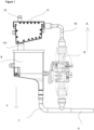
Figure 1 : is the top perspective view of the oven of the present invention. -
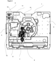
Figure 2 : is the front perspective view of the steam generator, the tank and the separation receptacle of the present invention. - The following numerals are referred to in the description of the present invention:
- 1. Oven
- 2. Body
- 3. Water container
- 4. Supply line
- 5. Steam generator
- 6. Tank
- 6.1 Buffer region
- 6.2 Active region
- 6.3 Empty region
- 7. First connection member
- 8. Control unit
- 9. Sensor
- 10. Separation receptacle
- 11. Second connection member
- 12. Third connection member
- 13. Delivery line
- Y: Water delivery direction
- A: Water filling direction
- The present invention relates to an oven (1) comprising a body (2) wherein the foodstuffs to be cooked are placed; a water container (3) which is placed on the body (2) and which is filled with water; at least one supply line (4) which is connected to the water container (3) at one end; at least one steam generator (5) to which the water taken from the supply line (4) is delivered; at least one tank (6); and at least one first connection member (7) which connects the steam generator (5) and the tank (6) to each other. The steam generator (5) and the tank (6) are positioned longitudinally and vertically so as to be parallel to each other.
- In an embodiment of the present invention, the steam generator (5) and the tank (6) are positioned at a level lower than the level at which the water enters the supply line (4).
- In an embodiment of the present invention, the tank (6) comprises a buffer region (6.1) which continuously contains water, an active region (6.2) where the water level changes and an empty region (6.3) for preventing overflow.
- In an embodiment of the present invention, the oven (1) comprises a control unit (8) which is configured to instruct the supply line (4) to deliver water when the water level in the active region (6.2) drops to a predetermined value and to control the water levels in the buffer region (6.1) and active region (6.2). By means of the present invention, the buffer region (6.1) is enabled to remain constantly filled with water during the cooking process, thus preventing the steam generator (5) from remaining dry during the operating time of the oven (1). Thus, the need for the supply line (4) in the oven (1) to constantly deliver the water or for the oven (1) to be constantly turned on and off is eliminated. Thus, energy efficiency and safe operation of the system are provided.
- In an embodiment of the present invention, approximately 10% to 20% of the tank (6) volume is allocated to the buffer region (6.1), approximately 50% to 70% to the active region (6.2), and approximately 20% to 30% to the empty region (6.3) so as to prevent the boiling water in the steam generator (5) from overflowing.
- In an embodiment of the present invention, the oven (1) further comprises at least one sensor (9) which is positioned at any point in and/or on the tank (6), which measures the water level in the tank (6) and which transmits the water level information to the control unit (8) when the water level in the active region (6.2) drops to a predetermined value.
- In another embodiment of the present invention, the water level control is monitored by means of an algorithm in the control unit (8). The oven (1) comprises a control unit (8) which is configured to enable the supply line (4) to operate within a predetermined time interval and to stop the delivery of water from the supply line (4) to the tank (6) when the operating time of the supply line (4) reaches said predetermined value. When the water volume in the tank (6) drops to a certain level, the control unit (8) gives the command to deliver water to the tank (6) again.
- The oven (1) of the invention comprises at least one supply line (4) which ensures the delivery of water in a top to bottom direction (Y); a steam generator (5) which is positioned longitudinally and vertically; a tank (6) which is positioned longitudinally and vertically so as to be parallel to the steam generator (5); and a first connection member (7) which connects the steam generator (5) and the tank (6) to each other, wherein the water delivered from the supply line (4) is delivered to the steam generator (5) and/or the tank (6) in a bottom to top direction (A).
- In an embodiment of the present invention, the oven (1) further comprises a separation receptacle (10) which separates the water and the steam from each other and which is positioned at a higher level than the steam generator (5) and the tank (6).
- In an embodiment of the present invention, the connection of the steam generator (5) and the separation receptacle (10) is provided by at least a second connection member (11), and the connection of the tank (6) and the separation receptacle (10) is provided by at least a third connection member (12).
- In an embodiment of the present invention, the supply line (4) provides connection with the water container (3) at one end and with the steam generator (5) or the tank (6) or the separation receptacle (10) at the other end so as to ensure that the water is taken from the water container (3) and delivered to the steam generator (5) and/or the tank (6) in a top to bottom direction (Y) with the effect of gravity.
- In an embodiment of the present invention, the second connection member (11) is connected to the steam generator (5) at one end and the separation receptacle (10) at the other end so as to provide the connection between the steam generator (5) and the separator vessel (10), and delivers the water and the steam leaving the steam generator (5) together to the separation receptacle (10).
- In an embodiment of the present invention, the third connection member (12) is connected to the separation receptacle (10) at one end and the tank (6) at the other end so as to provide the connection between the separation receptacle (10) and the tank (6), and delivers the water separated in the separation receptacle (10) to the tank (6).
- In an embodiment of the present invention, the oven (1) further comprises at least one delivery line (13) which provides the delivery of the steam leaving the separation receptacle (10). The delivery line (13) is connected to the separation receptacle (10) at one end and the body (2) at the other end so as to provide the connection between the separation receptacle (10) and the body (2), and delivers the steam separated in the separation receptacle (10) to the body (2).
- In an embodiment of the present invention, the water is delivered in the direction Y through the supply line (4) upon the instruction of the control unit (8). Thus, the water is delivered to the steam generator (5) and/or the tank (6) with the effect of gravity through the supply line (4). Then, the water is delivered in the direction A into the steam generator (5) and the tank (6), which are positioned in a vertical position so as to be parallel to each other. The buffer region (6.1) is completely filled with water by means of the water delivered to the tank (6). The steam generator (5) and the tank (6), which are connected to each other by means of the first connection member (7) and form a U-shaped structure, operate on the principle of communicating vessels. The water in the steam generator (5) and the tank (6) always remains at the same level. This level is controlled by the active region (6.2) where the water level changes. Due to its structure, the steam generator (5) is a generator with a small water volume. The large volume tank (6) positioned parallel to the steam generator (5) can store a volume of water sufficient to meet the needs of the system. The control unit (8) checks the water level information as the amount of water in the steam generator (5) decreases and ensures that the water is delivered to the tank (6) through the supply line (4) when the water level in the active region (6.2) decreases to a predetermined value. With the principle of communicating vessels, continuous water flow is ensured from the tank (6) to the steam generator (5). The empty region (6.3) in the tank (6) prevents the water in the tank (6) from overflowing and ensures the safe delivery of steam to the interior of the body (2).
- In another embodiment of the present invention, the supply line (4) provides connection with the separation receptacle (10) from another end which is not connected to the body (2), and takes the water from the water container (3) and transmits the same to the separation receptacle (10) in a top to bottom direction (Y) with the effect of gravity. Then, the water is delivered from the separation receptacle (10) to the tank (6) through the third connection member (12). Afterwards, the water is delivered in the direction A into the steam generator (5) and the tank (6), which are positioned in a vertical position so as to be parallel to each other. In the steam generator (5) and the tank (6), which are connected to each other through the first connection member (7) and form a U-shaped structure, with the principle of communicating vessels, the water is delivered from the tank (6) to the steam generator (5) through the first connection member (7) such that the water in the steam generator (5) and the tank (6) always remains at the same level. Thus, the exhaust/waste/used hot water coming from the steam generator (5) delivered through the third connection member (12) is ensured to mix with the water in the active region (6.2) so as to create an internal circulation instead of discharge.
- In an embodiment of the present invention, the supply line (4) is a water supply line which provides delivery by means of at least one pump or valve.
- In the preferred embodiment of the present invention, the steam generator (5) is a tube-type generator (5).
- In an embodiment of the present invention, the steam generator (5) and the tank (6) are positioned parallel to each other and in a vertical position, under the separation receptacle (10).
- In an embodiment of the present invention, the oven (1) is a household oven (1) with steam cooking function.
Claims (7)
- An oven (1) comprising a body (2) wherein the foodstuffs to be cooked are placed; a water container (3) disposed on the body (2); at least one supply line (4) connected to the water container (3) at one end; and at least one steam generator (5) to which the water taken from the supply line (4) is delivered, characterized by a tank (6) which is connected to said steam generator (5) by means of at least a first connection member (7), which is positioned longitudinally and vertically so as to be parallel to the steam generator (5) and which comprises a buffer region (6.1) where the water level is kept fixed, an active region (6.2) where the water level changes and an empty region (6.3) for preventing overflow; and a control unit (8) which is configured to instruct the supply line (4) to deliver water when the water level in the active region (6.2) drops to a predetermined value and to control the water levels in the buffer region (6.1) and the active region (6.2).
- An oven (1) as in Claim 1, characterized by the steam generator (5) and the tank (6) which are positioned at a level lower than the level at which the water enters the supply line (4).
- An oven (1) as in Claim 1 or 2, characterized by the tank (6) with 1 0% to 20% of its volume allocated to the buffer region (6.1), 50% to 70% to the active region (6.2), and 20% to 30% to the empty region (6.3).
- An oven (1) as in any one of the above claims, characterized by at least one sensor (9) which is positioned at any point in and/or on the tank (6), which measures the water level in the tank (6) and which transmits the water level information to the control unit (8) when the water level in the active region (6.2) drops to a predetermined value.
- An oven (1) as in any one of Claims 1 to 4, characterized by the control unit (8) which is configured to enable the supply line (4) to operate within a predetermined time interval and to stop the delivery of water from the supply line (4) to the tank (6) when the operating time of the supply line (4) reaches said predetermined value.
- An oven (1) as in any one of the above claims, characterized by a separation receptacle (10) which is positioned at a level above the steam generator (5) and the tank (6), which is connected to the steam generator (5) by at least one second connection member (11) and connected to the tank (6) by at least one third connection member (12), and which separates the water and the steam coming from the steam generator (5).
- An oven (1) as in any one of the above claims, characterized by the supply line (4) which is connected to the water container (3) at one end and with the steam generator (5) or the tank (6) or the separation receptacle (10) at the other end so as to ensure that the water is taken from the water container (3) and delivered to the steam generator (5) and/or the tank (6) in a top to bottom direction (Y) with the effect of gravity.
Applications Claiming Priority (1)
| Application Number | Priority Date | Filing Date | Title |
|---|---|---|---|
| TR202220585 | 2022-12-27 |
Publications (1)
| Publication Number | Publication Date |
|---|---|
| EP4394257A1 true EP4394257A1 (en) | 2024-07-03 |
Family
ID=89030046
Family Applications (1)
| Application Number | Title | Priority Date | Filing Date |
|---|---|---|---|
| EP23212981.7A Withdrawn EP4394257A1 (en) | 2022-12-27 | 2023-11-29 | An oven with steam cooking function |
Country Status (1)
| Country | Link |
|---|---|
| EP (1) | EP4394257A1 (en) |
Citations (3)
| Publication number | Priority date | Publication date | Assignee | Title |
|---|---|---|---|---|
| US20130042768A1 (en) | 2010-04-28 | 2013-02-21 | Sharp Kabushiki Kaisha | Cooking device |
| US20190309956A1 (en) * | 2018-04-09 | 2019-10-10 | Whirlpool Corporation | Steam generating system |
| US20220057087A1 (en) * | 2018-10-23 | 2022-02-24 | Lg Electronics Inc. | Electronic cooking apparatus having steam supply device |
-
2023
- 2023-11-29 EP EP23212981.7A patent/EP4394257A1/en not_active Withdrawn
Patent Citations (3)
| Publication number | Priority date | Publication date | Assignee | Title |
|---|---|---|---|---|
| US20130042768A1 (en) | 2010-04-28 | 2013-02-21 | Sharp Kabushiki Kaisha | Cooking device |
| US20190309956A1 (en) * | 2018-04-09 | 2019-10-10 | Whirlpool Corporation | Steam generating system |
| US20220057087A1 (en) * | 2018-10-23 | 2022-02-24 | Lg Electronics Inc. | Electronic cooking apparatus having steam supply device |
Similar Documents
| Publication | Publication Date | Title |
|---|---|---|
| EP2387319B1 (en) | Oven steam generator system and method for generating steam | |
| CN101112288B (en) | Heating cooker and steam generating device for the same | |
| US9113741B2 (en) | Apparatus and method for cooking portioned food pieces in batches | |
| JP4409612B1 (en) | Cooker | |
| CN103892693B (en) | Hydropenia detection method, hydropenia detecting device and steam cooking vessel | |
| US7238922B2 (en) | Steam cooker | |
| RU2531415C2 (en) | Cooking device | |
| CN104603536A (en) | steam generator | |
| EP3553392B1 (en) | Cooking appliance | |
| JP2002272604A (en) | Heating method and heating device using superheated steam | |
| CN109124325B (en) | Cooking apparatus | |
| CN109124344B (en) | Cooking apparatus | |
| KR101734407B1 (en) | Cooking Apparatus for Injecting Thermal Energy in a Downward Direction | |
| JP2006112746A (en) | Steam generator | |
| CN108261077B (en) | Cooking apparatus | |
| JP5064325B2 (en) | Steam cooker | |
| CN203100196U (en) | Water boiler with temperature control and heat preservation functions | |
| CN207666844U (en) | Steam spray device | |
| CN105496214A (en) | Coffee brewing device | |
| EP4394258A1 (en) | An oven with steam cooking function | |
| CN103654371A (en) | Steaming tool with double-heating device | |
| CN209436922U (en) | A kind of internal-circulation type heating device | |
| KR101715668B1 (en) | Vapor supply device for hairdressing and beauty care, and vapor supply method for hairdressing and beauty care | |
| CN210124616U (en) | Instant heating type water heating container | |
| JP2010032120A (en) | Steam generator and heating cooker |
Legal Events
| Date | Code | Title | Description |
|---|---|---|---|
| PUAI | Public reference made under article 153(3) epc to a published international application that has entered the european phase |
Free format text: ORIGINAL CODE: 0009012 |
|
| STAA | Information on the status of an ep patent application or granted ep patent |
Free format text: STATUS: REQUEST FOR EXAMINATION WAS MADE |
|
| 17P | Request for examination filed |
Effective date: 20231129 |
|
| AK | Designated contracting states |
Kind code of ref document: A1 Designated state(s): AL AT BE BG CH CY CZ DE DK EE ES FI FR GB GR HR HU IE IS IT LI LT LU LV MC ME MK MT NL NO PL PT RO RS SE SI SK SM TR |
|
| STAA | Information on the status of an ep patent application or granted ep patent |
Free format text: STATUS: EXAMINATION IS IN PROGRESS |
|
| 17Q | First examination report despatched |
Effective date: 20250409 |
|
| STAA | Information on the status of an ep patent application or granted ep patent |
Free format text: STATUS: THE APPLICATION IS DEEMED TO BE WITHDRAWN |
|
| 18D | Application deemed to be withdrawn |
Effective date: 20250812 |