EP4394251A1 - Ensemble buse, chambre de combustion et turbine à gaz comprenant celui-ci - Google Patents
Ensemble buse, chambre de combustion et turbine à gaz comprenant celui-ci Download PDFInfo
- Publication number
- EP4394251A1 EP4394251A1 EP24150056.0A EP24150056A EP4394251A1 EP 4394251 A1 EP4394251 A1 EP 4394251A1 EP 24150056 A EP24150056 A EP 24150056A EP 4394251 A1 EP4394251 A1 EP 4394251A1
- Authority
- EP
- European Patent Office
- Prior art keywords
- fuel
- tube
- supply
- air
- turbine
- Prior art date
- Legal status (The legal status is an assumption and is not a legal conclusion. Google has not performed a legal analysis and makes no representation as to the accuracy of the status listed.)
- Granted
Links
Images

Classifications
-
- F—MECHANICAL ENGINEERING; LIGHTING; HEATING; WEAPONS; BLASTING
- F23—COMBUSTION APPARATUS; COMBUSTION PROCESSES
- F23R—GENERATING COMBUSTION PRODUCTS OF HIGH PRESSURE OR HIGH VELOCITY, e.g. GAS-TURBINE COMBUSTION CHAMBERS
- F23R3/00—Continuous combustion chambers using liquid or gaseous fuel
- F23R3/28—Continuous combustion chambers using liquid or gaseous fuel characterised by the fuel supply
- F23R3/286—Continuous combustion chambers using liquid or gaseous fuel characterised by the fuel supply having fuel-air premixing devices
-
- F—MECHANICAL ENGINEERING; LIGHTING; HEATING; WEAPONS; BLASTING
- F02—COMBUSTION ENGINES; HOT-GAS OR COMBUSTION-PRODUCT ENGINE PLANTS
- F02C—GAS-TURBINE PLANTS; AIR INTAKES FOR JET-PROPULSION PLANTS; CONTROLLING FUEL SUPPLY IN AIR-BREATHING JET-PROPULSION PLANTS
- F02C7/00—Features, components parts, details or accessories, not provided for in, or of interest apart form groups F02C1/00 - F02C6/00; Air intakes for jet-propulsion plants
- F02C7/22—Fuel supply systems
-
- F—MECHANICAL ENGINEERING; LIGHTING; HEATING; WEAPONS; BLASTING
- F23—COMBUSTION APPARATUS; COMBUSTION PROCESSES
- F23R—GENERATING COMBUSTION PRODUCTS OF HIGH PRESSURE OR HIGH VELOCITY, e.g. GAS-TURBINE COMBUSTION CHAMBERS
- F23R3/00—Continuous combustion chambers using liquid or gaseous fuel
- F23R3/02—Continuous combustion chambers using liquid or gaseous fuel characterised by the air-flow or gas-flow configuration
- F23R3/04—Air inlet arrangements
- F23R3/10—Air inlet arrangements for primary air
- F23R3/12—Air inlet arrangements for primary air inducing a vortex
- F23R3/14—Air inlet arrangements for primary air inducing a vortex by using swirl vanes
-
- F—MECHANICAL ENGINEERING; LIGHTING; HEATING; WEAPONS; BLASTING
- F23—COMBUSTION APPARATUS; COMBUSTION PROCESSES
- F23R—GENERATING COMBUSTION PRODUCTS OF HIGH PRESSURE OR HIGH VELOCITY, e.g. GAS-TURBINE COMBUSTION CHAMBERS
- F23R3/00—Continuous combustion chambers using liquid or gaseous fuel
- F23R3/02—Continuous combustion chambers using liquid or gaseous fuel characterised by the air-flow or gas-flow configuration
- F23R3/16—Continuous combustion chambers using liquid or gaseous fuel characterised by the air-flow or gas-flow configuration with devices inside the flame tube or the combustion chamber to influence the air or gas flow
-
- F—MECHANICAL ENGINEERING; LIGHTING; HEATING; WEAPONS; BLASTING
- F05—INDEXING SCHEMES RELATING TO ENGINES OR PUMPS IN VARIOUS SUBCLASSES OF CLASSES F01-F04
- F05D—INDEXING SCHEME FOR ASPECTS RELATING TO NON-POSITIVE-DISPLACEMENT MACHINES OR ENGINES, GAS-TURBINES OR JET-PROPULSION PLANTS
- F05D2220/00—Application
- F05D2220/30—Application in turbines
- F05D2220/32—Application in turbines in gas turbines
-
- F—MECHANICAL ENGINEERING; LIGHTING; HEATING; WEAPONS; BLASTING
- F05—INDEXING SCHEMES RELATING TO ENGINES OR PUMPS IN VARIOUS SUBCLASSES OF CLASSES F01-F04
- F05D—INDEXING SCHEME FOR ASPECTS RELATING TO NON-POSITIVE-DISPLACEMENT MACHINES OR ENGINES, GAS-TURBINES OR JET-PROPULSION PLANTS
- F05D2240/00—Components
- F05D2240/35—Combustors or associated equipment
Definitions
- a turbo machine refers to an apparatus that generates a driving force used to generate electric power by using fluid (especially, gas) passing through the turbo machine. Therefore, such a turbo machine is usually installed and used together with a generator.
- the turbo machine may include a gas turbine, a steam turbine, and a wind power turbine.
- the gas turbine is an apparatus that generates combustion gas by mixing compressed air and natural gas and by combusting the mixture, and generates a driving force for generation of electric power by using the combustion gas.
- the steam turbine is an apparatus that heats water to generate steam and generates a driving force for generation of electric power by using the steam.
- the wind power turbine is an apparatus that converts wind power into a driving force for generation of electric power.
- the gas turbine includes a compressor, a combustor, and a turbine.
- the compressor includes multiple compressor vanes and multiple compressor blades which are alternately disposed in a compressor casing.
- the compressor is configured to intake external air through a compressor inlet scroll strut. The intaken air is compressed by the compressor vanes and the compressor blades while passing through an inner portion of the compressor.
- the combustor receives compressed air compressed in the compressor, and mixes the compressed air with fuel.
- the combustor ignites fuel mixed with compressed air by using an igniter, thereby generating high-temperature and high-pressure combustion gas.
- Such generated combustion gas is supplied to the turbine.
- the turbine includes a plurality of turbine vanes and a plurality of turbine blades which are alternately disposed in a turbine casing.
- the turbine receives combustion gas generated in the combustor, and passes the combustion gas through an inner portion of the turbine. The combustion gas passing through the inner portion of the turbine rotates the turbine blades, and the combustion gas that has completely passed through the inner portion of the turbine is discharged to an outside of the turbine through a turbine diffuser.
- the steam turbine includes an evaporator and a turbine.
- the evaporator generates steam by heating water supplied from outside.
- the turbine of the steam turbine includes a plurality of turbine vanes and a plurality of turbine blades which are alternately disposed in the turbine casing.
- the turbine in the steam turbine passes steam generated by the evaporator rather than combustion gases through the inside thereof, thereby rotating the turbine blades.
- the gas turbine may use hydrogen as fuel.
- a structure that supplies fuel and air to a combustion chamber by using a plurality of tubes is proposed.
- the fuel injection structure using the plurality of tubes has the advantage of improving the mixing efficiency of fuel and gas and reducing the generation of nitrogen oxides since air and fuel flows are distributed through the plurality of tubes.
- an objective of the present disclosure is to provide a nozzle assembly, a combustor using the same, and a gas turbine, in which the mixing structure of fuel and air is improved to improve mixing efficiency thereof so that the overall length of a tube is decreased, thereby decreasing the overall size of a combustor and reducing the generation of nitrogen oxides.
- the combustor configured to mix compressed air supplied from a compressor of the gas turbine with fuel and to combust a mixture of the compressed air and the fuel, the combustor being configured to supply a generated combustion gas to a turbine of the gas turbine, and the combustor including: a nozzle casing; a liner connected to an end portion of the nozzle casing adjacent to the turbine, the liner having an inner portion provided with a combustion chamber in which a mixture of compressed air and fuel is combusted; a transition piece connected to an end portion of the liner adjacent to the turbine, the transition piece being configured to supply a combustion gas generated from the combustion chamber to the turbine; and the nozzle assembly mounted inside the nozzle casing and configured to inject fuel and compressed air into the combustion chamber, wherein the nozzle assembly includes: the hollow nozzle frame; the mixture supply tube having a plurality of tubes configured to supply a mixture of air and fuel to the combustion chamber; the fuel supply part configured to supply fuel to the mixture supply tube; the
- the fuel supply part of the present disclosure may include: a fuel supply tube disposed in a center of the nozzle frame and formed along a longitudinal direction of the nozzle frame; and a return member configured to move fuel supplied through the fuel supply tube to a rear side of the nozzle frame, and a fuel injection hole configured to allow the return member and the inside of the tube to communicate with each other may be formed in the injection member so that fuel supplied through the return member flows into the tube.
- the injection member of the present disclosure may include: a first hollow tube disposed in a center of the tube; and a plurality of supports formed in radial shapes outward from the first hollow tube, and the supports may include five supports and be disposed at equal angles from each other, and the fuel injection hole configured to inject fuel supplied from the return member may be formed in an upstream part of each of the supports.
- a fuel supply hole configured to allow the fuel supply part and the tube of the present disclosure to communicate with each other and to supply fuel of the fuel supply part to the tube may be formed in the tube, and a central axis of the fuel supply hole may be formed to be inclined with respect to a central axis of the tube so that fuel is injected toward a center of the tube.
- the mixing structure of fuel and air is improved to improve mixing efficiency so that the overall length of a tube is decreased, thereby decreasing the overall size of the combustor and reducing the generation of nitrogen oxides.
- a torque tube functioning as a torque transmission member for transmitting rotational torque generated from the turbine 12 to the compressor 11 is disposed between the compressor rotor that is positioned at the rearmost stage of the compressor 11 and the turbine rotor that is positioned at the foremost stage of the turbine 12.
- the torque tube may include a plurality of torque tube disks arranged in a three-stage structure, but this is only one of various embodiments of the present disclosure.
- the torque tube may include a plurality of torque tube disks arranged in a structure of equal to or more than four stages or a structure of equal to or less than two stages.
- Each of the compressor rotors includes a compressor disk and compressor blades.
- a plurality of compressor disks e.g. fourteen disks
- each of the compressor disks is coupled by a tie rod such that the compressor disks are not spaced apart from each other in an axial direction.
- the tie rod passing through each center portion of the compressor disks, each of the compressor disks is arranged along the axial direction.
- the compressor disks adjacent to each other are disposed such that facing surfaces of adjacent compressor disks are pressed by the tie rod so that the adjacent compressor disks cannot independently rotate.
- a plurality of compressor blades is radially coupled to an outer circumferential surface of each of the compressor disks.
- a plurality of compressor vanes which is mounted in an annular shape on an inner circumferential surface of the compressor casing is disposed between the compressor blades on the basis of respective stages.
- the compressor vanes are in a fixed state such that the compressor vanes do not rotate, and to align a flow of compressed air that has passed through the compressor blades and to guide the compressed air to the compressor blades which are positioned at the downstream side.
- the compressor casing and the compressor vanes may be comprehensively defined as a compressor stator.
- the compressor stator may further include a compressor inlet scroll strut in addition to the compressor casing and the compressor vanes.
- the compressor inlet scroll strut is connected to the front stage of the compressor casing, and guides external air to the inlet of the compressor casing.
- a compressor vane located at the foremost stage is referred to as an inlet guide vane.
- the inlet guide vane serves to guide air flowing into the compressor casing to a compressor blade and a compressor vane disposed on a rear stage.
- a deswirler functioning as a guide vane may be mounted in the compressor 11 of the gas turbine 10, in which the deswirler is configured to increase a pressure of fluid flowing into an inlet of the combustor 100 and to adjust a flow angle of the fluid to a designed flow angle.
- the turbine 12 basically has a structure similar to that of the compressor 11. That is, the turbine 12 is also provided with a plurality of turbine rotors similar to the compressor rotors of the compressor 11. Accordingly, each of the turbine rotors 14 also includes a turbine disk and a plurality of turbine blades radially disposed around the turbine disk. A plurality of turbine vanes which is mounted in an annular shape in the turbine casing is provided between the turbine blades on the basis of respective stages. Furthermore, the turbine vanes guide the flow direction of the combustion gas passing through the turbine blades. In this case, in order to distinguish the turbine casing and the turbine vanes from the turbine rotor, the turbine casing and the turbine vanes may be comprehensively defined as a turbine stator.
- the combustor 100 includes an outer can 110, an outer head 111, an inner can 120, and an inner head 121.
- the outer can 110 is formed in the shape of a hollow cylinder, and receives fuel from the outside.
- the outer head 111 is provided on the front of the outer can 110 and covers the outer can 110.
- the inner can 120 is disposed inside the outer can 110 and is formed in the shape of a hollow cylinder.
- compressed air moves from the rear to the front between the inner can 120 and the outer can 110, and fuel and compressed air are injected into the inner can through the front.
- the combustion chamber 1210 space in which combustion occurs inside the inner can 120 is called a combustion chamber 1210.
- the inner head 121 is installed on the front of the inner can 120, mixes the fuel and compressed air which are supplied thereinto, and supplies the fuel and compressed air to the inside of the inner can 120.
- the inner head 121 includes a head plate 122 and a plurality of nozzle assemblies 123.
- the head plate 122 covers the front of the inner can 120.
- the plurality of nozzle assemblies 123 is installed on the front of the head plate 122, and mixes fuel and compressed air and supplies the fuel and compressed air to the rear of the head plate.
- the nozzle assemblies 123 are installed in a structure in which one nozzle group is disposed in the central portion of the head plate 122, and a plurality of remaining nozzle groups is located at a radial outer side of the one nozzle group of the central portion to surround the one nozzle group.
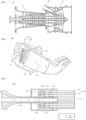
- the nozzle assembly 1400 includes a nozzle frame 1410, a mixture supply tube 1420, a fuel supply part 1430, an air supply part 1440, and a mixing part 1450.
- the nozzle frame 1410 is formed in the form of a hollow tube, and includes the mixture supply tube 1420, the fuel supply part 1430, the air supply part 1440, a return member 1432, and the mixing part 1450 disposed therein.
- the mixture supply tube 1420 includes a plurality of tubes 1421. A first end of each of the tubes 1421 is connected to the air supply part 1440, and a second end of the tube 1421 communicates with the combustion chamber 1210.
- the tube 1421 is supported by a pair of tube seats 1411 arranged by being spaced apart from each other along a longitudinal direction of the tube 1421.
- the fuel supply part 1430 includes a fuel supply tube 1431 provided longitudinally in the center of the nozzle frame 1410, and the return member 1432 disposed at the outside of the fuel supply tube.
- the fuel may be hydrogen.
- hydrogen is used as the fuel, but other fuels other than hydrogen, such as LNG, may also be applied.
- the return member 1432 moves fuel moved to the downstream side (the right side of FIG. 3 ) of the nozzle frame in the fuel supply tube to the upstream side of the nozzle frame 1410, and then supplies to the tubes 1421 of the mixture supply tube 1420.
- the return member 1432 may be configured as a member that defines a space between the tubes.
- the air supply part 1440 is formed on the upstream side of the tubes 1421.
- the air supply part 1440 supplies air supplied from the outside of the nozzle assembly to the tubes 1421.
- the air may be compressed air supplied from the compressor.
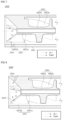
- the injection member 1451 is formed inside the tube 1421 and injects fuel supplied from the fuel supply part 1430 toward air passing through the tube 1421.
- the injection member 1451 includes a first hollow tube 1451a and supports 1451b, and has a central flow path formed in the center of the tube 1421 so that the mixture of fuel and air can flow to the center of the tube 1421 along an axial direction thereof.
- the first hollow tube 1451a is disposed along the axis of the tube 1421 in the center of the tube 1421 and is formed in a tube being hollow inside to constitute a flow path of the mixture of fuel and air.
- Each of the supports 1451b has a first end connected to the first hollow tube 1451a, and a second end connected to the tube 1421, and supports the first hollow tube 1451a.
- the support 1451b includes a plurality of supports, and the plurality of supports is formed in radial shapes outward from the first hollow tube 1451a.
- the supports 1451b include five supports and are disposed at equal intervals of 72° from each other relative to the center of the first hollow tube.
- the supports 1451b are disposed at equal angles 72° with respect to the center of the tube 1421 so that the supports can evenly supply fuel to the entire area of the tube 1421.
- the swirl vane 1452 includes a second hollow tube 1452a and a plurality of blades 1452b.
- the second hollow tube 1452a is formed as a hollow tube having a communication path formed in a center thereof, with the communication path communicating with the first hollow tube 1451a.
- the second hollow tube 1452a is formed at the downstream side of the injection member and is disposed in the center of the tube.
- the plurality of blades is formed in spiral shapes on the outer circumferential surface of the second hollow tube 1452a.
- the blades 1452b allow fuel and air supplied through the outside of the first hollow tube to form a spiral flow (SF) so that the fuel and air can mix with each other.
- SF spiral flow
- FIG. 7 is a cross-sectional view of a mixing part according to a second embodiment of the present disclosure the nozzle assembly.
- configurations other than a configuration related to the fuel injection hole 3433 are the same as the configurations of the nozzle assembly according to the first embodiment described above and thus description thereof will be omitted.
Landscapes
- Engineering & Computer Science (AREA)
- Chemical & Material Sciences (AREA)
- Combustion & Propulsion (AREA)
- Mechanical Engineering (AREA)
- General Engineering & Computer Science (AREA)
Applications Claiming Priority (1)
| Application Number | Priority Date | Filing Date | Title |
|---|---|---|---|
| KR1020230000313A KR102737490B1 (ko) | 2023-01-02 | 2023-01-02 | 노즐 어셈블리, 연소기 및 이를 포함하는 가스터빈 |
Publications (2)
| Publication Number | Publication Date |
|---|---|
| EP4394251A1 true EP4394251A1 (fr) | 2024-07-03 |
| EP4394251B1 EP4394251B1 (fr) | 2026-04-22 |
Family
ID=89474264
Family Applications (1)
| Application Number | Title | Priority Date | Filing Date |
|---|---|---|---|
| EP24150056.0A Active EP4394251B1 (fr) | 2023-01-02 | 2024-01-02 | Ensemble buse, chambre de combustion et turbine à gaz comprenant celui-ci |
Country Status (4)
| Country | Link |
|---|---|
| US (1) | US12601489B2 (fr) |
| EP (1) | EP4394251B1 (fr) |
| JP (1) | JP7686920B2 (fr) |
| KR (1) | KR102737490B1 (fr) |
Families Citing this family (1)
| Publication number | Priority date | Publication date | Assignee | Title |
|---|---|---|---|---|
| US12326259B2 (en) | 2020-11-24 | 2025-06-10 | Pratt & Whitney Canada Corp. | Fuel swirler for pressure fuel nozzles |
Citations (8)
| Publication number | Priority date | Publication date | Assignee | Title |
|---|---|---|---|---|
| US20010052229A1 (en) * | 1998-02-10 | 2001-12-20 | General Electric Company | Burner with uniform fuel/air premixing for low emissions combustion |
| US20140096502A1 (en) * | 2010-09-30 | 2014-04-10 | Andreas Karlsson | Burner for a gas turbine |
| US20190264921A1 (en) * | 2018-02-23 | 2019-08-29 | Doosan Heavy Industries & Construction Co., Ltd. | Nozzle for combustors, combustor, and gas turbine including the same |
| KR20190109955A (ko) * | 2018-03-19 | 2019-09-27 | 두산중공업 주식회사 | 연소기용 노즐, 연소기 및 이를 포함하는 가스 터빈 |
| KR20220114937A (ko) * | 2021-02-09 | 2022-08-17 | 두산에너빌리티 주식회사 | 마이크로 믹서 및 이를 포함하는 연소기 |
| WO2022176302A1 (fr) * | 2021-02-19 | 2022-08-25 | 三菱パワー株式会社 | Brûleur de combustion à pré-mélange, injecteur de combustible et turbine à gaz |
| KR102474179B1 (ko) | 2021-01-15 | 2022-12-06 | 두산에너빌리티 주식회사 | 멀티튜브를 갖는 연소기 및 이를 포함하는 가스터빈 |
| KR20230000313A (ko) | 2021-06-24 | 2023-01-02 | 고등기술연구원연구조합 | 살균 장치 및 이를 구비한 살균 장치 작동 케이스 |
Family Cites Families (11)
| Publication number | Priority date | Publication date | Assignee | Title |
|---|---|---|---|---|
| US8607569B2 (en) * | 2009-07-01 | 2013-12-17 | General Electric Company | Methods and systems to thermally protect fuel nozzles in combustion systems |
| US8683804B2 (en) * | 2009-11-13 | 2014-04-01 | General Electric Company | Premixing apparatus for fuel injection in a turbine engine |
| US8850821B2 (en) * | 2011-10-07 | 2014-10-07 | General Electric Company | System for fuel injection in a fuel nozzle |
| US9353950B2 (en) * | 2012-12-10 | 2016-05-31 | General Electric Company | System for reducing combustion dynamics and NOx in a combustor |
| US9927124B2 (en) * | 2015-03-26 | 2018-03-27 | Ansaldo Energia Switzerland AG | Fuel nozzle for axially staged fuel injection |
| US20170248318A1 (en) | 2016-02-26 | 2017-08-31 | General Electric Company | Pilot nozzles in gas turbine combustors |
| KR102153014B1 (ko) | 2019-04-05 | 2020-09-07 | 두산중공업 주식회사 | 연소기 및 이를 포함하는 가스터빈 |
| US20200400314A1 (en) * | 2019-06-21 | 2020-12-24 | United Technologies Corporation | Cooling fuel injector system for an attritable engine |
| KR102189308B1 (ko) | 2020-02-10 | 2020-12-10 | 두산중공업 주식회사 | 연소기용 노즐, 연소기 및 이를 포함하는 가스 터빈 |
| JP7349403B2 (ja) * | 2020-04-22 | 2023-09-22 | 三菱重工業株式会社 | バーナー集合体、ガスタービン燃焼器及びガスタービン |
| KR102437977B1 (ko) * | 2021-01-18 | 2022-08-30 | 두산에너빌리티 주식회사 | 노즐 어셈블리, 연소기 및 이를 포함하는 가스터빈 |
-
2023
- 2023-01-02 KR KR1020230000313A patent/KR102737490B1/ko active Active
-
2024
- 2024-01-02 US US18/402,414 patent/US12601489B2/en active Active
- 2024-01-02 EP EP24150056.0A patent/EP4394251B1/fr active Active
- 2024-01-04 JP JP2024000351A patent/JP7686920B2/ja active Active
Patent Citations (8)
| Publication number | Priority date | Publication date | Assignee | Title |
|---|---|---|---|---|
| US20010052229A1 (en) * | 1998-02-10 | 2001-12-20 | General Electric Company | Burner with uniform fuel/air premixing for low emissions combustion |
| US20140096502A1 (en) * | 2010-09-30 | 2014-04-10 | Andreas Karlsson | Burner for a gas turbine |
| US20190264921A1 (en) * | 2018-02-23 | 2019-08-29 | Doosan Heavy Industries & Construction Co., Ltd. | Nozzle for combustors, combustor, and gas turbine including the same |
| KR20190109955A (ko) * | 2018-03-19 | 2019-09-27 | 두산중공업 주식회사 | 연소기용 노즐, 연소기 및 이를 포함하는 가스 터빈 |
| KR102474179B1 (ko) | 2021-01-15 | 2022-12-06 | 두산에너빌리티 주식회사 | 멀티튜브를 갖는 연소기 및 이를 포함하는 가스터빈 |
| KR20220114937A (ko) * | 2021-02-09 | 2022-08-17 | 두산에너빌리티 주식회사 | 마이크로 믹서 및 이를 포함하는 연소기 |
| WO2022176302A1 (fr) * | 2021-02-19 | 2022-08-25 | 三菱パワー株式会社 | Brûleur de combustion à pré-mélange, injecteur de combustible et turbine à gaz |
| KR20230000313A (ko) | 2021-06-24 | 2023-01-02 | 고등기술연구원연구조합 | 살균 장치 및 이를 구비한 살균 장치 작동 케이스 |
Also Published As
| Publication number | Publication date |
|---|---|
| KR20240108696A (ko) | 2024-07-09 |
| JP2024096119A (ja) | 2024-07-12 |
| US12601489B2 (en) | 2026-04-14 |
| EP4394251B1 (fr) | 2026-04-22 |
| KR102737490B1 (ko) | 2024-12-04 |
| US20240219029A1 (en) | 2024-07-04 |
| JP7686920B2 (ja) | 2025-06-03 |
Similar Documents
| Publication | Publication Date | Title |
|---|---|---|
| EP4394251A1 (fr) | Ensemble buse, chambre de combustion et turbine à gaz comprenant celui-ci | |
| KR102651451B1 (ko) | 가스터빈 연소기 및 이를 구비한 가스터빈 | |
| KR102437978B1 (ko) | 노즐 어셈블리, 연소기 및 이를 포함하는 가스터빈 | |
| KR102792861B1 (ko) | 노즐 어셈블리, 연소기 및 이를 포함하는 가스터빈 | |
| KR102792850B1 (ko) | 노즐 어셈블리, 연소기 및 이를 포함하는 가스터빈 | |
| KR102720522B1 (ko) | 제트 노즐, 연소기 및 이를 포함하는 가스터빈 | |
| KR102762420B1 (ko) | 노즐 어셈블리, 연소기 및 이를 포함하는 가스터빈 | |
| KR102859744B1 (ko) | 혼합기, 노즐 어셈블리, 연소기 및 이를 포함하는 가스터빈 | |
| EP4299984A1 (fr) | Buse creuse, chambre de combustion comprenant une buse creuse, et turbine à gaz comprenant une chambre de combustion | |
| US12305859B2 (en) | Nozzle assembly, combustor, and gas turbine including same | |
| KR20220135409A (ko) | 노즐 어셈블리, 연소기 및 이를 포함하는 가스터빈 | |
| KR102932022B1 (ko) | 혼합기, 노즐 어셈블리, 연소기 및 이를 포함하는 가스터빈 | |
| KR102762434B1 (ko) | 노즐 어셈블리, 연소기 및 이를 포함하는 가스터빈 | |
| KR102762429B1 (ko) | 노즐 어셈블리, 연소기 및 이를 포함하는 가스터빈 | |
| KR102804110B1 (ko) | 노즐 어셈블리, 연소기 및 이를 포함하는 가스터빈 | |
| KR102720523B1 (ko) | 제트 노즐, 연소기 및 이를 포함하는 가스터빈 | |
| KR102720524B1 (ko) | 제트 노즐, 연소기 및 이를 포함하는 가스터빈 | |
| US20240175579A1 (en) | Nozzle assembly, combustor, and gas turbine including same | |
| KR20240108687A (ko) | 노즐 어셈블리, 연소기 및 이를 포함하는 가스터빈 |
Legal Events
| Date | Code | Title | Description |
|---|---|---|---|
| PUAI | Public reference made under article 153(3) epc to a published international application that has entered the european phase |
Free format text: ORIGINAL CODE: 0009012 |
|
| STAA | Information on the status of an ep patent application or granted ep patent |
Free format text: STATUS: REQUEST FOR EXAMINATION WAS MADE |
|
| 17P | Request for examination filed |
Effective date: 20240102 |
|
| AK | Designated contracting states |
Kind code of ref document: A1 Designated state(s): AL AT BE BG CH CY CZ DE DK EE ES FI FR GB GR HR HU IE IS IT LI LT LU LV MC ME MK MT NL NO PL PT RO RS SE SI SK SM TR |
|
| RBV | Designated contracting states (corrected) |
Designated state(s): AL AT BE BG CH CY CZ DE DK EE ES FI FR GB GR HR HU IE IS IT LI LT LU LV MC ME MK MT NL NO PL PT RO RS SE SI SK SM TR |
|
| GRAP | Despatch of communication of intention to grant a patent |
Free format text: ORIGINAL CODE: EPIDOSNIGR1 |
|
| STAA | Information on the status of an ep patent application or granted ep patent |
Free format text: STATUS: GRANT OF PATENT IS INTENDED |
|
| INTG | Intention to grant announced |
Effective date: 20250811 |
|
| RIN1 | Information on inventor provided before grant (corrected) |
Inventor name: SHERSHNYOV, BORYS |
|
| GRAJ | Information related to disapproval of communication of intention to grant by the applicant or resumption of examination proceedings by the epo deleted |
Free format text: ORIGINAL CODE: EPIDOSDIGR1 |
|
| STAA | Information on the status of an ep patent application or granted ep patent |
Free format text: STATUS: REQUEST FOR EXAMINATION WAS MADE |
|
| GRAP | Despatch of communication of intention to grant a patent |
Free format text: ORIGINAL CODE: EPIDOSNIGR1 |
|
| STAA | Information on the status of an ep patent application or granted ep patent |
Free format text: STATUS: GRANT OF PATENT IS INTENDED |
|
| INTG | Intention to grant announced |
Effective date: 20251127 |
|
| GRAS | Grant fee paid |
Free format text: ORIGINAL CODE: EPIDOSNIGR3 |
|
| GRAA | (expected) grant |
Free format text: ORIGINAL CODE: 0009210 |
|
| STAA | Information on the status of an ep patent application or granted ep patent |
Free format text: STATUS: THE PATENT HAS BEEN GRANTED |
|
| AK | Designated contracting states |
Kind code of ref document: B1 Designated state(s): AL AT BE BG CH CY CZ DE DK EE ES FI FR GB GR HR HU IE IS IT LI LT LU LV MC ME MK MT NL NO PL PT RO RS SE SI SK SM TR |
|
| REG | Reference to a national code |
Ref country code: CH Ref legal event code: F10 Free format text: ST27 STATUS EVENT CODE: U-0-0-F10-F00 (AS PROVIDED BY THE NATIONAL OFFICE) Effective date: 20260422 Ref country code: GB Ref legal event code: FG4D |