EP4394215A1 - Sliding component - Google Patents
Sliding component Download PDFInfo
- Publication number
- EP4394215A1 EP4394215A1 EP22861290.9A EP22861290A EP4394215A1 EP 4394215 A1 EP4394215 A1 EP 4394215A1 EP 22861290 A EP22861290 A EP 22861290A EP 4394215 A1 EP4394215 A1 EP 4394215A1
- Authority
- EP
- European Patent Office
- Prior art keywords
- groove
- sliding
- fluid inlet
- fluid
- seal ring
- Prior art date
- Legal status (The legal status is an assumption and is not a legal conclusion. Google has not performed a legal analysis and makes no representation as to the accuracy of the status listed.)
- Pending
Links
Images









Classifications
-
- F—MECHANICAL ENGINEERING; LIGHTING; HEATING; WEAPONS; BLASTING
- F16—ENGINEERING ELEMENTS AND UNITS; GENERAL MEASURES FOR PRODUCING AND MAINTAINING EFFECTIVE FUNCTIONING OF MACHINES OR INSTALLATIONS; THERMAL INSULATION IN GENERAL
- F16J—PISTONS; CYLINDERS; SEALINGS
- F16J15/00—Sealings
- F16J15/16—Sealings between relatively-moving surfaces
- F16J15/32—Sealings between relatively-moving surfaces with elastic sealings, e.g. O-rings
- F16J15/3244—Sealings between relatively-moving surfaces with elastic sealings, e.g. O-rings with hydrodynamic pumping action
-
- F—MECHANICAL ENGINEERING; LIGHTING; HEATING; WEAPONS; BLASTING
- F16—ENGINEERING ELEMENTS AND UNITS; GENERAL MEASURES FOR PRODUCING AND MAINTAINING EFFECTIVE FUNCTIONING OF MACHINES OR INSTALLATIONS; THERMAL INSULATION IN GENERAL
- F16J—PISTONS; CYLINDERS; SEALINGS
- F16J15/00—Sealings
- F16J15/16—Sealings between relatively-moving surfaces
- F16J15/34—Sealings between relatively-moving surfaces with slip-ring pressed against a more or less radial face on one member
- F16J15/3404—Sealings between relatively-moving surfaces with slip-ring pressed against a more or less radial face on one member and characterised by parts or details relating to lubrication, cooling or venting of the seal
- F16J15/3408—Sealings between relatively-moving surfaces with slip-ring pressed against a more or less radial face on one member and characterised by parts or details relating to lubrication, cooling or venting of the seal at least one ring having an uneven slipping surface
-
- F—MECHANICAL ENGINEERING; LIGHTING; HEATING; WEAPONS; BLASTING
- F16—ENGINEERING ELEMENTS AND UNITS; GENERAL MEASURES FOR PRODUCING AND MAINTAINING EFFECTIVE FUNCTIONING OF MACHINES OR INSTALLATIONS; THERMAL INSULATION IN GENERAL
- F16C—SHAFTS; FLEXIBLE SHAFTS; ELEMENTS OR CRANKSHAFT MECHANISMS; ROTARY BODIES OTHER THAN GEARING ELEMENTS; BEARINGS
- F16C33/00—Parts of bearings; Special methods for making bearings or parts thereof
- F16C33/02—Parts of sliding-contact bearings
- F16C33/04—Brasses; Bushes; Linings
- F16C33/06—Sliding surface mainly made of metal
- F16C33/10—Construction relative to lubrication
-
- F—MECHANICAL ENGINEERING; LIGHTING; HEATING; WEAPONS; BLASTING
- F16—ENGINEERING ELEMENTS AND UNITS; GENERAL MEASURES FOR PRODUCING AND MAINTAINING EFFECTIVE FUNCTIONING OF MACHINES OR INSTALLATIONS; THERMAL INSULATION IN GENERAL
- F16C—SHAFTS; FLEXIBLE SHAFTS; ELEMENTS OR CRANKSHAFT MECHANISMS; ROTARY BODIES OTHER THAN GEARING ELEMENTS; BEARINGS
- F16C17/00—Sliding-contact bearings for exclusively rotary movement
- F16C17/04—Sliding-contact bearings for exclusively rotary movement for axial load only
- F16C17/045—Sliding-contact bearings for exclusively rotary movement for axial load only with grooves in the bearing surface to generate hydrodynamic pressure, e.g. spiral groove thrust bearings
-
- F—MECHANICAL ENGINEERING; LIGHTING; HEATING; WEAPONS; BLASTING
- F16—ENGINEERING ELEMENTS AND UNITS; GENERAL MEASURES FOR PRODUCING AND MAINTAINING EFFECTIVE FUNCTIONING OF MACHINES OR INSTALLATIONS; THERMAL INSULATION IN GENERAL
- F16C—SHAFTS; FLEXIBLE SHAFTS; ELEMENTS OR CRANKSHAFT MECHANISMS; ROTARY BODIES OTHER THAN GEARING ELEMENTS; BEARINGS
- F16C33/00—Parts of bearings; Special methods for making bearings or parts thereof
- F16C33/02—Parts of sliding-contact bearings
- F16C33/04—Brasses; Bushes; Linings
- F16C33/06—Sliding surface mainly made of metal
- F16C33/10—Construction relative to lubrication
- F16C33/1025—Construction relative to lubrication with liquid, e.g. oil, as lubricant
- F16C33/106—Details of distribution or circulation inside the bearings, e.g. details of the bearing surfaces to affect flow or pressure of the liquid
- F16C33/1065—Grooves on a bearing surface for distributing or collecting the liquid
-
- F—MECHANICAL ENGINEERING; LIGHTING; HEATING; WEAPONS; BLASTING
- F16—ENGINEERING ELEMENTS AND UNITS; GENERAL MEASURES FOR PRODUCING AND MAINTAINING EFFECTIVE FUNCTIONING OF MACHINES OR INSTALLATIONS; THERMAL INSULATION IN GENERAL
- F16C—SHAFTS; FLEXIBLE SHAFTS; ELEMENTS OR CRANKSHAFT MECHANISMS; ROTARY BODIES OTHER THAN GEARING ELEMENTS; BEARINGS
- F16C33/00—Parts of bearings; Special methods for making bearings or parts thereof
- F16C33/02—Parts of sliding-contact bearings
- F16C33/04—Brasses; Bushes; Linings
- F16C33/06—Sliding surface mainly made of metal
- F16C33/10—Construction relative to lubrication
- F16C33/1025—Construction relative to lubrication with liquid, e.g. oil, as lubricant
- F16C33/106—Details of distribution or circulation inside the bearings, e.g. details of the bearing surfaces to affect flow or pressure of the liquid
- F16C33/107—Grooves for generating pressure
-
- F—MECHANICAL ENGINEERING; LIGHTING; HEATING; WEAPONS; BLASTING
- F16—ENGINEERING ELEMENTS AND UNITS; GENERAL MEASURES FOR PRODUCING AND MAINTAINING EFFECTIVE FUNCTIONING OF MACHINES OR INSTALLATIONS; THERMAL INSULATION IN GENERAL
- F16C—SHAFTS; FLEXIBLE SHAFTS; ELEMENTS OR CRANKSHAFT MECHANISMS; ROTARY BODIES OTHER THAN GEARING ELEMENTS; BEARINGS
- F16C33/00—Parts of bearings; Special methods for making bearings or parts thereof
- F16C33/72—Sealings
- F16C33/74—Sealings of sliding-contact bearings
-
- F—MECHANICAL ENGINEERING; LIGHTING; HEATING; WEAPONS; BLASTING
- F16—ENGINEERING ELEMENTS AND UNITS; GENERAL MEASURES FOR PRODUCING AND MAINTAINING EFFECTIVE FUNCTIONING OF MACHINES OR INSTALLATIONS; THERMAL INSULATION IN GENERAL
- F16J—PISTONS; CYLINDERS; SEALINGS
- F16J15/00—Sealings
- F16J15/16—Sealings between relatively-moving surfaces
- F16J15/32—Sealings between relatively-moving surfaces with elastic sealings, e.g. O-rings
- F16J15/3248—Sealings between relatively-moving surfaces with elastic sealings, e.g. O-rings provided with casings or supports
- F16J15/3252—Sealings between relatively-moving surfaces with elastic sealings, e.g. O-rings provided with casings or supports with rigid casings or supports
- F16J15/3256—Sealings between relatively-moving surfaces with elastic sealings, e.g. O-rings provided with casings or supports with rigid casings or supports comprising two casing or support elements, one attached to each surface, e.g. cartridge or cassette seals
-
- F—MECHANICAL ENGINEERING; LIGHTING; HEATING; WEAPONS; BLASTING
- F16—ENGINEERING ELEMENTS AND UNITS; GENERAL MEASURES FOR PRODUCING AND MAINTAINING EFFECTIVE FUNCTIONING OF MACHINES OR INSTALLATIONS; THERMAL INSULATION IN GENERAL
- F16J—PISTONS; CYLINDERS; SEALINGS
- F16J15/00—Sealings
- F16J15/16—Sealings between relatively-moving surfaces
- F16J15/34—Sealings between relatively-moving surfaces with slip-ring pressed against a more or less radial face on one member
- F16J15/3404—Sealings between relatively-moving surfaces with slip-ring pressed against a more or less radial face on one member and characterised by parts or details relating to lubrication, cooling or venting of the seal
- F16J15/3408—Sealings between relatively-moving surfaces with slip-ring pressed against a more or less radial face on one member and characterised by parts or details relating to lubrication, cooling or venting of the seal at least one ring having an uneven slipping surface
- F16J15/3412—Sealings between relatively-moving surfaces with slip-ring pressed against a more or less radial face on one member and characterised by parts or details relating to lubrication, cooling or venting of the seal at least one ring having an uneven slipping surface with cavities
Definitions
- Patent Citation 1 JP 6444492 B2 (Page 12, FIG. 7 )
- the groove includes a fluid inlet and outlet groove opening to the sealed fluid side space or the leakage side space on the side of the groove, and a dynamic pressure generation groove communicating with the fluid inlet and outlet groove and extending in a circumferential direction, and the fluid inlet and outlet groove is deeper than the dynamic pressure generation groove. According to this preferable configuration, since a sufficient amount of the fluid can be held in the fluid inlet and outlet groove, poor lubrication for the dynamic pressure generation groove can be prevented.
- the inclined surface is provided on the first sliding ring. According to this preferable configuration, regardless of a sliding state of the pair of sliding rings, a communication state between the inclined surface and the fluid space can always be maintained constant.
- the fluid inlet and outlet groove communicates with one of the sealed fluid side space and the leakage side space on a radially inner side, and a radially outermost position of the dynamic pressure generation groove is located radially outside a radially outermost position of the fluid inlet and outlet groove. According to this preferable configuration, a large communication region between the dynamic pressure generation groove and the fluid inlet and outlet groove can be ensured.
- the fluid inlet and outlet groove communicates with one of the sealed fluid side space and the leakage side space on a radially outer side, and a radially innermost position of the dynamic pressure generation groove is located radially inside a radially innermost position of the fluid inlet and outlet groove. According to this preferable configuration, a large communication region between the dynamic pressure generation groove and the fluid inlet and outlet groove can be ensured.
- the fluid inlet and outlet groove communicates with the sealed fluid side space
- the sliding surface of the first sliding ring or the second sliding ring is provided with a spiral groove communicating with the leakage side space and not communicating with the sealed fluid side space.
- the first sliding ring is provided with another inclined surface that is formed an edge portion thereof on the leakage side space and that faces another fluid space formed between the spiral groove and the second sliding ring and that is expanded toward the leakage side space. According to this preferable configuration, the fluid on the leakage side is smoothly introduced in or out from the other fluid space along the other inclined surface.
- examples of SiC include sintered bodies using boron, aluminum, carbon, or the like as a sintering aid, and materials consisting of two or more phases with different components and compositions, such as SiC in which graphite particles are dispersed, reaction-sintered SiC consisting of SiC and Si, SiC-TiC, and SiC-TiN, and as carbon, mixed carbon of a carbonaceous substance and a graphitic substance, resin-molded carbon, sintered carbon, and the like can be used.
- metal materials, resin materials, surface modification materials (e.g., coating materials), composite materials, and the like can also be applied.
- portions of the sliding surface 11 other than the dynamic pressure generation mechanisms 13 are lands 12 disposed on the same plane and forming a flat surface.
- the flat surface of the lands 12 functions as a sliding surface that substantially slides against the sliding surface 21 of the rotating seal ring 20.
- the expansion surfaces 18 (48 in the present embodiment) are arranged between the inclined grooves 81 adjacent to each other in the circumferential direction at the edge portion 10e' on the radially outer side of the sliding surface 11.
- the expansion surfaces 18 have a so-called chamfered shape.
- the inclined grooves 81 extend continuously with the spiral grooves 16.
- the spiral grooves 16 extend in an arcuate shape from the radially outer side toward the radially inner side while being inclined with a clockwise component.
- the spiral grooves 16 communicate with the outer space S2, and do not communicate with the inner space S1.
- the spiral grooves 16 are formed with a constant depth in the circumferential direction.
- the spiral grooves 16 are not limited to extending in an arcuate shape while being inclined, and may extend linearly.
- the force caused by the positive pressure generated at the radially inner-side end portion 16B of the spiral groove 16 and in the vicinity thereof is added to the force caused by the positive pressure generated at the end portion 15A of the Rayleigh step 15 and in the vicinity thereof, and the sliding surfaces 11 and 21 are further separated from each other compared to when the speed is low. Accordingly, the atmosphere A inside the spiral groove 16 indicated by an arrow L2 mainly flows into the gap between the sliding surfaces 11 and 21.
- the annular groove 180 can collect the sealed fluid F flowing from the outer space S2 into the gap between the sliding surfaces.
- the sealed fluid F flowing to the radially inner side of the annular groove 180 is pushed back to the radially outer side by the spiral grooves 160', and is collected into the annular groove 180. Accordingly, both lubricity and sealability can be achieved.
- FIG. 14 illustrates when the rotating seal ring rotates.
- the mechanical seal of the seventh embodiment is different from the mechanical seal of the first embodiment in that the expansion surfaces 17 and the expansion surfaces 18 are not provided.
- a plurality of the inclined grooves 61 provided in the circumferential direction and having the respective inclined surfaces 6 do not communicate with the inclined grooves 61, which are adjacent thereto in the circumferential direction, in the circumferential direction.
- the plurality of inclined grooves 61 are independently formed in the circumferential direction.
- the expansion surfaces 18 are not provided at the edge portion 210e on the inner space S1 side.
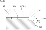
- an inclined surface 36 extends from the end edge on the radially inner side of the bottom surface 14a of the fluid inlet and outlet groove 14 to the radially inner side, and unlike the first embodiment, the inclined surface 36 is not continuous with an inner peripheral surface of the stationary seal ring 310.
- an end surface 19a extending from a radially inner end of the inclined surface 36 in parallel to the flat surface of the lands 12 extends further to the radially inner side, and the end surface 19a is continuous with the expansion surface 17.
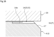
- the sealed fluid F can be smoothly supplied to the first fluid inlet and outlet space S10 by the expansion surface 17, there is no need to process inclined grooves and the like in addition to the expansion surface 17, and the stationary seal ring 410 can be easily manufactured.
- an expansion surface 517 is formed at an edge portion 521e on the radially inner side of a sliding surface 521 of a rotating seal ring 520.
- the expansion surface 517 has a tapered shape that is inclined from the sliding surface 521 toward an inner peripheral surface 520g of the rotating seal ring 520 in a direction away from the stationary seal ring 510.
- the expansion surface 517 is continuous with a first fluid inlet and outlet space S10' (refer to a dotted portion in FIG. 17 ), and expands toward the inner space S1 side.
- the sealed fluid F can be smoothly supplied to the first fluid inlet and outlet space S10' along the expansion surface 517.
- a mode in which the expansion surface 517 is formed in an annular shape namely, a mode in which a communication space is formed over the entire circumference has been provided as an example; however, the present invention is not limited thereto, and the expansion surface may be interrupted in the circumferential direction.
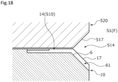
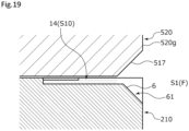
- the mechanical seal of the eleventh embodiment is configured by a combination of the stationary seal ring 10 of the first embodiment and the rotating seal ring 520 of the tenth embodiment.
- the first fluid inlet and outlet space S10 is expanded in the depth direction toward the inner space S1 side by the inclined groove 61 of the stationary seal ring 210 and a space formed between the stationary seal ring 210 and the expansion surface 517 of the rotating seal ring 520. Accordingly, the sealed fluid F can be smoothly supplied to the first fluid inlet and outlet space S10.
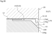
- an expansion surface 170 having a stepped shape is formed instead of the expansion surface 17 of the stationary seal ring 10 of the first embodiment.
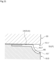
- the expansion surface and the inclined surface of the stationary seal ring may have a curved surface shape that bulges to the radially inner side and in a direction opposite to the depth direction in a cross-sectional view.
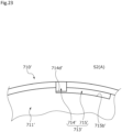
- a stationary seal ring 710 of the mechanical seal of the fifteenth embodiment includes a dynamic pressure generation mechanism 713 on the radially inner side of a sliding surface 711.
- the dynamic pressure generation mechanism 713 includes a fluid inlet and outlet groove 714 and a Rayleigh step 715 as a dynamic pressure generation groove.
- the fluid inlet and outlet groove 714 communicates with the inner space S1.
- the Rayleigh step 715 extends clockwise from the radially outer side of the fluid inlet and outlet groove 714.
- a side surface 715b on the radially outer side of the Rayleigh step 715 is disposed radially outside an end surface 714d on the radially outer side of the fluid inlet and outlet groove 714.
- the Rayleigh step 715' extends clockwise from the radially inner side of the fluid inlet and outlet groove 714'.
- a side surface 715b' on the radially inner side of the Rayleigh step 715' is disposed radially inside an end surface 714d' on the radially inner side of the fluid inlet and outlet groove 714'.
- a stationary seal ring 710" of the mechanical seal of the seventeenth embodiment includes a dynamic pressure generation mechanism 713".
- the dynamic pressure generation mechanism 713" includes a fluid inlet and outlet groove 714" and a Rayleigh step 715" as a dynamic pressure generation groove.
- dynamic pressure generation grooves such as dimples (not illustrated) are formed on the radially outer side of the dynamic pressure generation mechanism 713".
- the Rayleigh step 715" extends from a radially outer end of the fluid inlet and outlet groove 714" to both sides in the circumferential direction.
- the radially outer end of the fluid inlet and outlet groove 714" is disposed at a center portion in the circumferential direction of the Rayleigh step 715".
- a radially inner end edge of a bottom surface 715a" of the Rayleigh step 715" is continuous with the expansion surface 17.
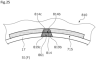
- side surfaces 814b and 814c of a fluid inlet and outlet groove 814 and side surfaces 819b and 819c partitioning an inclined groove 861 are inclined such that radially inner ends thereof are separated from each other in the circumferential direction.
- side surfaces 914b and 914c of a fluid inlet and outlet groove 914 and side surfaces 919b and 919c partitioning an inclined groove 961 are inclined such that radially inner ends thereof approach each other in the circumferential direction.
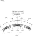
- a plurality of grooves 1230 and expansion surfaces 1217 are provided at an edge portion 1210e on the inner space S1 side of a sliding surface 1211 of a stationary seal ring 1210 of the twenty-second embodiment.
- a mode in which the atmosphere A exists in the inner space S1 and the sealed fluid F exists in the outer space S2 will be provided as an example.
- each of the grooves 1230 has a belt shape that is curved in an arcuate shape along the circumferential direction in an axial view.
- each of the grooves 1230 includes a bottom surface 1231 substantially parallel to a land 1212; a downstream end surface 1232 as a positive pressure generation portion that rises from a downstream end of the bottom surface 1231 to be substantially orthogonal to the land 1212; an upstream end surface 1233 as a negative pressure generation portion that rises from an upstream end of the bottom surface 1231 to be substantially orthogonal to the land 1212; a peripheral wall surface 1234 rising from a radially outer-side end of the bottom surface 1231 to be substantially orthogonal to the land 1212; an inclined surface 1216 that deepens in depth from a radially inner-side end edge of the bottom surface 1231 toward an inner peripheral surface of the stationary seal ring 1210; and side surfaces 1219b and 1219c rising from both circumferential end edges of the inclined surface 1216.
- the downstream end surface 1232 and the upstream end surface 1233 have the same radial length L10.
- a circumferential length L20 of the opening portion 1215 is longer than the radial length L10 of the downstream end surface 1232 and the upstream end surface 1233 (L10 ⁇ L20), and the circumferential length L20 is approximately five times the radial length L10.
- a plurality of grooves 1430 and expansion surfaces 1417 are provided at an edge portion 1410e on the radially inner side of a stationary seal ring 1410.
- the Rayleigh step and the reverse Rayleigh step have the same depth dimension
- the Rayleigh step and the reverse Rayleigh step may be formed with different depth dimensions.
- both may be the same or different from each other also in circumferential length and in radial length.
- the mechanical seal is an inside mechanical seal that seals the sealed fluid F tending to leak from the radially outer side toward the radially inner side of the sliding surfaces
- the mechanical seal may be an outside mechanical seal that seals the sealed fluid F tending to leak from the radially inner side toward the radially outer side of the sliding surfaces.
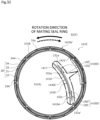
- a groove 1530 provided in a stationary seal ring 1510 includes a first groove portion 1530C and a second groove portion 1530D on the downstream side, and the second groove portion 1430D' on the upstream side in the twenty-fourth embodiment is not provided.
- the stationary seal ring 1510 may cope with only when the rotating seal ring 20 rotates relative to the stationary seal ring 1510 in the counterclockwise direction on the drawing sheet.
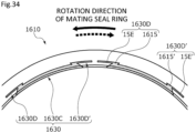
- An inclined portion 1615 of the second groove portion 1630D is inclined from a downstream end portion of the first groove portion 1630C to the upstream side in the rotation direction, and extends in the radial direction.
- an inclined portion 1615' of the second groove portion 1630D' is inclined from an upstream end portion of the first groove portion 1630C to the downstream side in the rotation direction, and extends in the radial direction.
- the inclined portion 1615 and the inclined portion 1615' are inclined and extend from the radially inner side toward the radially outer side in a direction toward each other when viewed in the axial direction, and the extension portions 15E and 15E' extend from the radially outer side thereof in a direction away from each other and in the circumferential direction.
- the sealed fluid F has been described as a high-pressure liquid, but is not limited thereto, and may be a gas or a low-pressure liquid or may be in the form of a mist that is a mixture of liquid and gas.
- the fluid on the leakage side has been described as the atmosphere A that is a low-pressure gas, but is not limited thereto, and may be a liquid or a high-pressure gas or may be in the form of a mist that is a mixture of liquid and gas.
- the bottom surface of the fluid inlet and outlet groove extends parallel to the flat surface of the land
- the present invention is not limited thereto, and for example, the bottom surface of the fluid inlet and outlet groove may be inclined to become shallower toward the leakage side. Namely, the inclined surface may be deeper toward the sealed fluid side at an angle different from that of the bottom surface of the fluid inlet and outlet groove.
- the depth of the fluid inlet and outlet groove may be deeper than the depth of the dynamic pressure generation groove, and may be applied to the twentieth and twenty-first embodiments.
- the depth of the fluid inlet and outlet groove may be the same as the depth of the dynamic pressure generation groove, and may be applied to the first to nineteenth embodiments.
Landscapes
- Engineering & Computer Science (AREA)
- General Engineering & Computer Science (AREA)
- Mechanical Engineering (AREA)
- Physics & Mathematics (AREA)
- Fluid Mechanics (AREA)
- Chemical & Material Sciences (AREA)
- Oil, Petroleum & Natural Gas (AREA)
- Mechanical Sealing (AREA)
- Joints Allowing Movement (AREA)
Abstract
Description
- The present invention relates to a sliding component, for example, a sliding component which is used for a shaft seal or a bearing of a rotating machine.
- As a sliding component that prevents a leakage of a sealed fluid around a rotating shaft of a rotating machine, for example, there is known a mechanical seal including a pair of sliding rings having an annular shape which rotate relative to each other and of which sliding surfaces slide against each other. In such a mechanical seal, in recent years, there has been a demand for reducing sliding-induced energy loss for environmental measures and the like, and a sliding surface of a sliding ring may be provided with positive pressure generation grooves which communicate with a sealed fluid side and of which one ends are closed in the sliding surface.
- For example, in a mechanical seal illustrated in Patent
Citation 1, on a sliding surface of one sliding ring, a plurality of positive pressure generation mechanisms, each including a fluid inlet and outlet groove extending in a radial direction, communicating with a sealed fluid side, and not communicating with a leakage side and a positive pressure generation groove communicating with the fluid inlet and outlet groove and extending in a relative rotation direction, are provided in a circumferential direction with land portions interposed therebetween. According to this configuration, during relative rotation of sliding rings, a sealed fluid is introduced into the positive pressure generation groove through the fluid inlet and outlet groove, and the sealed fluid concentrates on a wall portion of an end portion of the positive pressure generation groove in the relative rotation direction to generate a positive pressure, so that sliding surfaces are separated from each other, and a fluid film of the sealed fluid is formed between the sliding surfaces. Therefore, lubricity is improved and low friction is realized. - Patent Citation 1:
JP 6444492 B2 Page 12,FIG. 7 ) - In the mechanical seal of
Patent Citation 1, the sealed fluid inside the positive pressure generation groove moves toward the end portion in the relative rotation direction while following relative rotational sliding of a pair of the sliding rings, so that the sealed fluid is continuously supplied from a space on a sealed fluid side into the positive pressure generation groove through the fluid inlet and outlet groove. However, in the mechanical seal as disclosed in Patent Citation 1, since a corner portion formed by a bottom surface of the fluid inlet and outlet groove and a peripheral surface on the sealed fluid side of the sliding ring is formed at a right angle, when the sealed fluid is introduced from the space on the sealed fluid side into the fluid inlet and outlet groove, a vortex is likely to occur in the vicinity of the corner portion, and the sealed fluid is not effectively introduced into the fluid inlet and outlet groove, so that the amount of the sealed fluid inside the fluid inlet and outlet groove is reduced, which is a risk. - The present invention has been made in view of such problems, and an object of the present invention is to provide a sliding component that allows easy introduction-in or out of a fluid between a groove and a communicating space.
- In order to solve the foregoing problems, according to the present invention, there is provided a sliding component including a first sliding ring and a second sliding ring that have sliding surfaces rotating relative to each other and that partition a sealed fluid side space and a leakage side space off from each other, wherein the sliding surface of the first sliding ring is provided with a groove opening to at least one of the sealed fluid side space and the leakage side space, and at least one of the first sliding ring and the second sliding ling is provided with an inclined surface that is formed at an edge portion thereof on a side of the groove, that faces a fluid space formed between the groove of the first sliding ring and the second sliding ring, and that is expanded toward one of the sealed fluid side space and the leakage side space which is on the side of the groove. According to the aforesaid feature of the present invention, since a fluid smoothly moves to the fluid space from the space on the side of the groove, i.e., one of the sealed fluid side space and the leakage side space which is on side of the groove or to the space on the side of the groove from the fluid space , along the inclined surface expanded toward the space on the side of the groove, the fluid is easily introduced in or out between the fluid space and the space on the side of the groove.
- It may be preferable that the groove includes a fluid inlet and outlet groove opening to the sealed fluid side space or the leakage side space on the side of the groove, and a dynamic pressure generation groove communicating with the fluid inlet and outlet groove and extending in a circumferential direction, and the fluid inlet and outlet groove is deeper than the dynamic pressure generation groove. According to this preferable configuration, since a sufficient amount of the fluid can be held in the fluid inlet and outlet groove, poor lubrication for the dynamic pressure generation groove can be prevented.
- It may be preferable that the groove includes a fluid inlet and outlet groove opening to the sealed fluid side space or the leakage side space on the side of the groove, and a dynamic pressure generation groove communicating with the fluid inlet and outlet groove and extending in a circumferential direction, and the fluid inlet and outlet groove and the dynamic pressure generation groove are equal to each other in depth. According to this preferable configuration, the fluid is allowed to smoothly flow between the fluid inlet and outlet groove and the dynamic pressure generation groove.
- It may be preferable that the inclined surface is provided on the first sliding ring. According to this preferable configuration, regardless of a sliding state of the pair of sliding rings, a communication state between the inclined surface and the fluid space can always be maintained constant.
- It may be preferable that a bottom surface of the fluid inlet and outlet groove and the inclined surface form an obtuse angle. According to this preferable configuration, a vortex is less likely to occur at a boundary portion between the inclined surface and the bottom surface of the fluid inlet and outlet groove.
- It may be preferable that the first sliding ring is provided with an inclined groove defined by the inclined surface and side surfaces rising from both circumferential end edges of the inclined surface, at least one of the first sliding ring and the second sliding ling is provided with an expansion surface that is formed at an edge portion thereof on a side of the groove, that is expanded toward one of the sealed fluid side space and the leakage side space which is on the side of the groove, and a communication space partitioned off by the expansion surface and formed to extend in a circumferential direction communicates with the inclined groove. According to this preferable configuration, the sealed fluid can be introduced in or out from the inclined groove in a radial direction and in the circumferential direction.
- It may be preferable that the fluid inlet and outlet groove communicates with one of the sealed fluid side space and the leakage side space on a radially inner side, and a radially outermost position of the dynamic pressure generation groove is located radially outside a radially outermost position of the fluid inlet and outlet groove. According to this preferable configuration, a large communication region between the dynamic pressure generation groove and the fluid inlet and outlet groove can be ensured.
- It may be preferable that the fluid inlet and outlet groove communicates with one of the sealed fluid side space and the leakage side space on a radially outer side, and a radially innermost position of the dynamic pressure generation groove is located radially inside a radially innermost position of the fluid inlet and outlet groove. According to this preferable configuration, a large communication region between the dynamic pressure generation groove and the fluid inlet and outlet groove can be ensured.
- It may be preferable that the dynamic pressure generation grooves are provided on both circumferential sides of the fluid inlet and outlet groove, and the dynamic pressure generation grooves communicate with each other. According to this preferable configuration, since the dynamic pressure generation grooves on both circumferential sides of the fluid inlet and outlet groove communicate with each other, a cavitation generated at a communication portion and a periphery of the communication portion makes it difficult for the fluid to leak to the other space side.
- It may be preferable that the fluid inlet and outlet groove communicates with the sealed fluid side space, and the sliding surface of the first sliding ring or the second sliding ring is provided with a spiral groove communicating with the leakage side space and not communicating with the sealed fluid side space. According to this preferable configuration, during relative rotation of the pair of sliding rings, since the sliding surfaces can be separated from each other by the dynamic pressure generation groove and the spiral groove, and a fluid film can be formed between the sliding surfaces by the sealed fluid and a fluid on the leakage side, lubricity between the sliding surfaces is improved.
- It may be preferable that the first sliding ring is provided with another inclined surface that is formed an edge portion thereof on the leakage side space and that faces another fluid space formed between the spiral groove and the second sliding ring and that is expanded toward the leakage side space. According to this preferable configuration, the fluid on the leakage side is smoothly introduced in or out from the other fluid space along the other inclined surface.
- It may be preferable that a sealed fluid existing in the sealed fluid side space is a liquid, and a fluid existing in the leakage side space is a gas. According to this preferable configuration, during low-speed rotation of the pair of sliding rings, lubrication between the sliding surfaces can be performed by the liquid, and during high-speed rotation, lubrication between the sliding surfaces can be performed by the gas.
- It may be preferable that the groove is an open groove having a belt shape in which a circumferential length is longer than a radial length, and the open groove has at least an opening portion that opens to one of the sealed fluid side space and the leakage side space on the side of the groove along a circumferential direction.
- According to the thirteenth aspect, since the opening portion formed in the open groove is open along the circumferential direction, and the fluid in the space on the side of the groove is taken into the groove from the opening portion, even when the relative rotation speed of the sliding component increases, a large amount of the fluid in the space on the side of the groove can be taken into the groove from the opening portion, and a desired positive pressure can be generated between the sliding surfaces.
- It may be preferable that the open groove includes a first groove portion in which the opening portion is formed and which extends in the circumferential direction, and a second groove portion which extends with a radial component from a downstream end portion of the first groove portion in a relative rotation direction, and of which an end portion is closed. According to this preferable configuration, since the fluid in the space on the side of the groove can be introduced into the other space side further separated from the space on the side of the groove, the movement of the fluid on the other space side to the space on the side of the groove can be suppressed.
- It may be preferable that the second groove portion includes an inclined portion extending with a radial component, and an extension portion extending from the inclined portion in the circumferential direction. According to this preferable configuration, the introduction efficiency of the fluid in the space on the side of the groove into the second groove portion can be improved by the inclined portion, and a positive pressure can be generated at a position offset from the first groove portion in the radial direction by the extension portion.
- It may be preferable that the open groove is line-symmetrically formed with respect to a line extending in a radial direction. According to this preferable configuration, the sliding component can be used without being limited by a relative rotation direction.
-
-
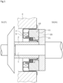
FIG. 1 is a longitudinal sectional view illustrating one example of a mechanical seal as a sliding component according to a first embodiment of the present invention. -
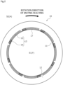
FIG. 2 is a view of a sliding surface of a stationary seal ring in the first embodiment when viewed in an axial direction. -
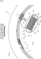
FIG. 3 is an enlarged view of the sliding surface of the stationary seal ring in the first embodiment when viewed in the axial direction. -
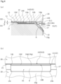
FIG. 4A is a cross-sectional view taken along line A-A ofFIG. 3 , andFIG. 4B is a view of a fluid inlet and outlet space and a periphery of the fluid inlet and outlet space when viewed from a radially inner side. -
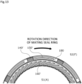
FIG. 5 is an enlarged view of a sliding surface of a stationary seal ring of a sliding component according to a second embodiment of the present invention when viewed in the axial direction. -
FIG. 6 is a cross-sectional view taken along line A'-A' ofFIG. 5 . -
FIG. 7 is a view of a sliding surface of a stationary seal ring of a sliding component according to a third embodiment of the present invention when viewed in the axial direction. -
FIG. 8 is an enlarged view of the sliding surface of the stationary seal ring in the third embodiment of the present invention when viewed in the axial direction. -
FIG. 9 is a cross-sectional view taken along line B-B ofFIG. 8 . -
FIG. 10 is a view illustrating a modification example of the stationary seal ring in the third embodiment of the present invention when viewed in the axial direction. -
FIG. 11 is an enlarged view of a sliding surface of a stationary seal ring of a sliding component according to a fourth embodiment of the present invention when viewed in the axial direction. -
FIG. 12 is an enlarged view of a sliding surface of a stationary seal ring of a sliding component according to a fifth embodiment of the present invention when viewed in the axial direction. -
FIG. 13 is an enlarged view of a sliding surface of a stationary seal ring of a sliding component according to a sixth embodiment of the present invention when viewed in the axial direction. -
FIG. 14A is an enlarged view of a sliding surface of a stationary seal ring of a sliding component according to a seventh embodiment of the present invention when viewed in the axial direction, andFIG. 14B is a cross-sectional view of the same taken along line C-C. -
FIG. 15 is a cross-sectional view of a fluid inlet and outlet groove of a sliding component according to an eighth embodiment of the present invention. -
FIG. 16 is a cross-sectional view of a fluid inlet and outlet groove of a sliding component according to a ninth embodiment of the present invention. -
FIG. 17 is a cross-sectional view of a fluid inlet and outlet groove of a sliding component according to a tenth embodiment of the present invention. -
FIG. 18 is a cross-sectional view of a fluid inlet and outlet groove of a sliding component according to an eleventh embodiment of the present invention. -
FIG. 19 is a cross-sectional view of a fluid inlet and outlet groove of a sliding component according to a twelfth embodiment of the present invention. -
FIG. 20 is a cross-sectional view of a fluid inlet and outlet groove of a sliding component according to a thirteenth embodiment of the present invention. -
FIG. 21 is a cross-sectional view of a fluid inlet and outlet groove of a sliding component according to a fourteenth embodiment of the present invention. -
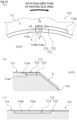
FIG. 22A is an enlarged view of a dynamic pressure generation groove of a sliding component according to a fifteenth embodiment of the present invention when viewed in the axial direction,FIG. 22B is a cross-sectional view taken along line G-G ofFIG. 22A, and FIG. 22C is a cross-sectional view of the same taken along line H-H. -
FIG. 23 is an enlarged view of a dynamic pressure generation groove of a sliding component according to a sixteenth embodiment of the present invention when viewed in the axial direction. -
FIG. 24A is an enlarged view of a dynamic pressure generation mechanism of a sliding component according to a seventeenth embodiment of the present invention when viewed in the axial direction, andFIG. 24B is a cross-sectional view taken along line E-E ofFIG. 24A . -
FIG. 25 is an enlarged view of a dynamic pressure generation mechanism of a sliding component according to an eighteenth embodiment of the present invention when viewed in the axial direction. -
FIG. 26 is an enlarged view of a dynamic pressure generation mechanism of a sliding component according to a nineteenth embodiment of the present invention when viewed in the axial direction. -
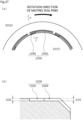
FIG. 27A is an enlarged view of a sliding surface of a stationary seal ring of a sliding component according to a twentieth embodiment of the present invention when viewed in the axial direction, andFIG. 27B is a cross-sectional view taken along line J-J ofFIG. 27A . -
FIG. 28A is an enlarged view of a sliding surface of a stationary seal ring of a sliding component according to a twenty-first embodiment of the present invention when viewed in the axial direction, andFIG. 28B is a cross-sectional view taken along line K-K ofFIG. 28A . -
FIG. 29 is a view of a sliding surface of a stationary seal ring of a sliding component according to a twenty-second embodiment of the present invention when viewed in the axial direction. -
FIG. 30 is an enlarged view of a groove of a sliding component according to the twenty-second embodiment of the present invention when viewed in the axial direction. -
FIG. 31 is an enlarged view of a groove of a sliding component according to a twenty-third embodiment of the present invention when viewed in the axial direction. -
FIG. 32 is a view of a sliding surface of a stationary seal ring of a sliding component according to a twenty-fourth embodiment of the present invention when viewed in the axial direction. -
FIG. 33 is an enlarged view of a groove of a sliding component according to a twenty-fifth embodiment of the present invention when viewed in the axial direction. -
FIG. 34 is an enlarged view of a groove of a sliding component according to a twenty-sixth embodiment of the present invention when viewed in the axial direction. - Modes for implementing a sliding component according to the present invention will be described below based on embodiments.
- A mechanical seal as a sliding component according to a first embodiment of the present invention will be described with reference to
FIGS. 1 to 4 . Incidentally, in the present embodiment, a description will be made based on the fact that a sealed fluid F exists in an inner space S1 of the mechanical seal, atmosphere A exists in an outer space S2, a radially inner side of sliding rings forming the mechanical seal is a sealed fluid side (high-pressure side), and a radially outer side is a leakage side (low-pressure side). In addition, for convenience of description, in the drawings, dots may be added to grooves and the like formed on a sliding surface. - A mechanical seal illustrated in
FIG. 1 is an outside mechanical seal that seals the sealed fluid F in the inner space S1 which tends to leak from the radially inner side toward the radially outer side of sliding surfaces, and that allows the outer space S2 to communicate with the atmosphere A. Incidentally, in the present embodiment, a mode in which the sealed fluid F is a high-pressure liquid and the atmosphere A is a gas having lower pressure than the sealed fluid F will be provided as an example. - The mechanical seal mainly includes a
rotating seal ring 20 as a second sliding ring, and astationary seal ring 10 as a first sliding ring. Therotating seal ring 20 has an annular shape, and is provided on arotating shaft 1 so as to be rotatable together with therotating shaft 1 via asleeve 2. Thestationary seal ring 10 has an annular shape, and is provided on a seal cover 5 fixed to ahousing 4 of an attached device, so as to be non-rotatable and movable in an axial direction. Thestationary seal ring 10 is biased in the axial direction by an elastic member 7, so that a slidingsurface 11 of thestationary seal ring 10 and a slidingsurface 21 of therotating seal ring 20 come into close contact with and slide against each other. Incidentally, the slidingsurface 21 of therotating seal ring 20 is a flat surface, and a recessed portion such as a groove is not provided on the flat surface. - The
stationary seal ring 10 and therotating seal ring 20 are typically made of SiC (as an example of hard material) or a combination of SiC and carbon (as an example of soft material), but are not limited thereto, and any sliding material can be applied as long as the sliding material can be used as a sliding material for a mechanical seal. Incidentally, examples of SiC include sintered bodies using boron, aluminum, carbon, or the like as a sintering aid, and materials consisting of two or more phases with different components and compositions, such as SiC in which graphite particles are dispersed, reaction-sintered SiC consisting of SiC and Si, SiC-TiC, and SiC-TiN, and as carbon, mixed carbon of a carbonaceous substance and a graphitic substance, resin-molded carbon, sintered carbon, and the like can be used. In addition, in addition to the above-described sliding materials, metal materials, resin materials, surface modification materials (e.g., coating materials), composite materials, and the like can also be applied. - As illustrated in
FIGS. 2 and3 , therotating seal ring 20 that is a mating seal ring slides clockwise relative to thestationary seal ring 10 as indicated by a solid arrow. - A plurality of dynamic
pressure generation mechanisms 13 are provided on the slidingsurface 11 of thestationary seal ring 10. The dynamic pressure generation mechanisms 13 (eight in the present embodiment) are evenly arranged in a circumferential direction on the radially inner side of the slidingsurface 11. - In addition, portions of the sliding
surface 11 other than the dynamicpressure generation mechanisms 13 arelands 12 disposed on the same plane and forming a flat surface. The flat surface of thelands 12 functions as a sliding surface that substantially slides against the slidingsurface 21 of therotating seal ring 20. - In addition, a plurality of inclined grooves 61 (refer to
FIG. 4 ) andexpansion surfaces 17 are provided at anedge portion 10e on an inner space S1 side of thestationary seal ring 10. In other words, the plurality ofinclined grooves 61 andexpansion surfaces 17 are provided at theedge portion 10e on the radially inner side of the slidingsurface 11 of thestationary seal ring 10. The expansion surfaces 17 (eight in the present embodiment) are arranged between theinclined grooves 61 adjacent to each other in the circumferential direction at theedge portion 10e on the radially inner side of the slidingsurface 11. In addition, the expansion surfaces 17 have a so-called chamfered shape. In addition, theinclined grooves 61 extend continuously with fluid inlet andoutlet grooves 14 to be described later of the dynamicpressure generation mechanisms 13. - In addition, the expansion surfaces 17 are tapered surfaces that are inclined to become deeper gradually from the flat surface of the
lands 12 toward an innerperipheral surface 10g of the stationary seal ring 10 (refer toFIG. 4 ). Incidentally, the expansion surfaces 17 may have unevenness, but are preferably flat surfaces. - As illustrated in
FIG. 3 , each of the dynamicpressure generation mechanisms 13 includes a fluid inlet andoutlet groove 14 as a fluid inlet and outlet groove and aRayleigh step 15 as a dynamic pressure generation groove. The fluid inlet andoutlet groove 14 extends in a radial direction so as to communicate with the inner space S1 and not to communicate with the outer space S2. TheRayleigh step 15 extends concentrically with thestationary seal ring 10 in the circumferential direction and in a clockwise direction from the radially outer side of the fluid inlet andoutlet groove 14. - As illustrated in
FIG. 4A , a depth D1 of the fluid inlet andoutlet groove 14 is formed deeper than a depth D2 of the Rayleigh step 15 (D1 > D2). Incidentally, theRayleigh step 15 is not limited to extending in an arcuate shape, and may extend linearly. In addition, theRayleigh step 15 is not limited to being provided concentrically with thestationary seal ring 10, and may be inclined in the circumferential direction. - As illustrated in
FIGS. 3 ,4A, and 4B , the fluid inlet andoutlet groove 14 includes abottom surface 14a, side surfaces 14b and 14c, and anend surface 14d on the radially outer side. Thebottom surface 14a extends parallel to the flat surface of thelands 12 in the radial direction. The side surfaces 14b and 14c rise from both circumferential end edges of thebottom surface 14a. Theend surface 14d on the radially outer side rises from a radially outer end of thebottom surface 14a, and is orthogonally connected to the side surfaces 14b and 14c. Anopening 14A communicating with theRayleigh step 15 is formed in theside surface 14b. In addition, anopening 14B communicating with the inner space S1 is formed on the radially inner side of the fluid inlet andoutlet groove 14. - An
inclined surface 6 extending to the radially inner side is continuously provided at anend edge 14g on the radially inner side of thebottom surface 14a of the fluid inlet andoutlet groove 14. In detail, theinclined surface 6 is inclined and extends linearly such that a depth of theinclined surface 6 becomes deeper from theend edge 14g on the radially inner side of thebottom surface 14a of the fluid inlet andoutlet groove 14 toward the innerperipheral surface 10g of thestationary seal ring 10, in other words, a distance from the slidingsurface 21 of therotating seal ring 20 increases. In addition, theinclined surface 6 is parallel to the expansion surfaces 17. - The
bottom surface 14a of the fluid inlet andoutlet groove 14 and theinclined surface 6 form an obtuse angle. Incidentally, in the present embodiment, a mode in which thebottom surface 14a of the fluid inlet andoutlet groove 14 and theinclined surface 6 form an obtuse angle is provided as an example; however, the present invention is not limited thereto, and a boundary between thebottom surface 14a and theinclined surface 6 may be continuous through a curved surface. In addition, a small step may be formed in a part of the vicinity of the boundary portion between thebottom surface 14a and theinclined surface 6. - Namely, the
inclined surface 6 is continuous with a first fluid inlet and outlet space S10 as a fluid space formed between the fluid inlet andoutlet groove 14 and the slidingsurface 21 of therotating seal ring 20, and expands toward the inner space S1 side in a direction away from therotating seal ring 20, namely, in a depth direction of the fluid inlet and outlet groove 14 (hereinafter, the distance away from therotating seal ring 20 and the direction thereof may be simply referred to as a "depth" and a "depth direction", respectively). Incidentally, it is preferably that theinclined surface 6 is a flat surface. - The
inclined surface 6 and theexpansion surface 17 are connected byside surfaces inclined surface 6. The side surfaces 19b and 19c are continuous with the side surfaces 14b and 14c of the fluid inlet andoutlet groove 14 in the radial direction. - Namely, the
inclined groove 61 surrounded by theinclined surface 6 and the side surfaces 19b and 19c is formed at theedge portion 10e on the inner space S1 side of thestationary seal ring 10. The first fluid inlet and outlet space S10 communicates with the inner space S1 through theinclined groove 61. - In addition, the
inclined grooves 61 adjacent to each other in the circumferential direction communicate with each other through a communication space S11. The communication space S11 is formed between theexpansion surface 17 and a radially inner-side end portion of therotating seal ring 20. - Next, the operation of the
stationary seal ring 10 and therotating seal ring 20 during relative rotation will be described with reference toFIGS. 3 and4 . Incidentally, the flow of the sealed fluid F or the atmosphere A inFIG. 3 is schematically illustrated without specifying a relative rotation speed of therotating seal ring 20. - First, when the
rotating seal ring 20 is not in rotation and is stopped, the sealed fluid F flows into the fluid inlet andoutlet groove 14. Incidentally, since thestationary seal ring 10 is biased to arotating seal ring 20 side by the elastic member 7, the slidingsurfaces surfaces - As illustrated in
FIG. 3 , in a state where therotating seal ring 20 rotates relative to thestationary seal ring 10, the sealed fluid F inside theRayleigh step 15 follows and moves in a rotation direction of therotating seal ring 20 due to shear with the slidingsurface 21, so that the sealed fluid F in the inner space S1 is drawn into the fluid inlet andoutlet groove 14 through theinclined groove 61. Namely, inside the fluid inlet andoutlet groove 14, as indicated by an arrow H1, the sealed fluid F moves from the fluid inlet andoutlet groove 14 toward anend portion 15A of theRayleigh step 15 on a downstream side in the relative rotation direction. - The sealed fluid F that has moved toward the
end portion 15A of theRayleigh step 15 is increased in pressure at theend portion 15A of theRayleigh step 15 and in the vicinity of theend portion 15A. Namely, a positive pressure is generated at theend portion 15A of theRayleigh step 15 and in the vicinity of theend portion 15A. - Since the depth D2 of the
Rayleigh step 15 is shallow, even when the movement amount of the sealed fluid F is small due to a low rotation speed of therotating seal ring 20, a positive pressure is generated at theend portion 15A of theRayleigh step 15 and in the vicinity of theend portion 15A. - In addition, the sliding
surfaces end portion 15A of theRayleigh step 15 and in the vicinity of theend portion 15A. Accordingly, the sealed fluid F inside the dynamicpressure generation mechanism 13 indicated by an arrow H2 mainly flows into a gap between the slidingsurfaces surfaces surfaces surfaces - In addition, the depth D1 of the fluid inlet and
outlet groove 14 is formed deeper than the depth D2 of theRayleigh step 15, and a large amount of the sealed fluid F can be held in the fluid inlet andoutlet groove 14. - In addition, as illustrated in
FIG. 4 , theinclined surface 6 inclined to expand in the depth direction is continuously provided on the radially inner side of thebottom surface 14a of the fluid inlet andoutlet groove 14. Accordingly, since the sealed fluid F that has flowed in in the radial direction from a deeper position than that of the fluid inlet andoutlet groove 14 is smoothly supplied to the first fluid inlet and outlet space S10 along theinclined surface 6, the sealed fluid F is easily introduced into the first fluid inlet and outlet space S10, and a reduction in the amount of the sealed fluid F in the first fluid inlet and outlet space S10 can be suppressed. In other words, a vortex is less likely to occur between thebottom surface 14a of the fluid inlet andoutlet groove 14 and theinclined surface 6. Namely, poor lubrication between the slidingsurfaces - In addition, since the
bottom surface 14a of the fluid inlet andoutlet groove 14 and theinclined surface 6 form an obtuse angle, a vortex is less likely to occur at the boundary portion between thebottom surface 14a and theinclined surface 6, namely, in the vicinity of theend edge 14g, and the sealed fluid F is smoothly supplied from theinclined surface 6 to the first fluid inlet and outlet space S10. - In addition, the
inclined surface 6 is provided continuously with thebottom surface 14a of the fluid inlet andoutlet groove 14. Namely, since theinclined surface 6 is provided on thestationary seal ring 10 provided with the fluid inlet andoutlet groove 14, regardless of the relative positions of thestationary seal ring 10 and therotating seal ring 20 in the circumferential direction or in the axial direction, a communication state between theinclined surface 6 and the fluid inlet andoutlet groove 14 can always be maintained constant. - In addition, since the plurality of
inclined grooves 61 are provided to be separated from each other in the circumferential direction, and theinclined grooves 61 adjacent to each other communicate with each other through the communication space S11, the sealed fluid F can be introduced into theinclined grooves 61 in the radial direction (refer to the arrow H1 inFIG. 3 ) and in the circumferential direction (refer to an arrow H3 inFIG. 3 ). - In addition, since the expansion surfaces 17 may be formed in an annular shape on the
stationary seal ring 10 by polishing or the like, and then the dynamicpressure generation mechanisms 13 may be processed by laser or the like, it is easy to manufacture thestationary seal ring 10. - In addition, since the
inclined groove 61 has the side surfaces 19b and 19c, the sealed fluid F introduced into theinclined groove 61 is guided toward the first fluid inlet and outlet space S10 in the radial direction. - In addition, since the
expansion surface 17 prevents the formation of an edge on the radially inner side of the fluid inlet andoutlet groove 14, damage to a radially inner-side end portion of the fluid inlet andoutlet groove 14 during relative rotational sliding can be avoided. - Incidentally, in the present embodiment, a mode in which the
expansion surface 17 extends between theinclined grooves 61 adjacent to each other in the circumferential direction has been provided as an example; however, the expansion surface may be interrupted on its way in the circumferential direction. - Next, a mechanical seal as a sliding component according to a second embodiment of the present invention will be described with reference to
FIGS. 5 and6 . Incidentally, the descriptions of configurations that are the same as and overlap with the configurations of the first embodiment will be omitted. - The mechanical seal of the second embodiment has the same configuration as the mechanical seal of the first embodiment, and is different in the rotation direction of the
rotating seal ring 20. As illustrated inFIG. 5 , therotating seal ring 20 slides counterclockwise relative to thestationary seal ring 10 as indicated by a solid arrow. - As illustrated in
FIG. 5 , in a state where therotating seal ring 20 rotates relative to thestationary seal ring 10, the sealed fluid F inside theRayleigh step 15 follows and moves in the rotation direction of therotating seal ring 20 due to shear with the slidingsurface 21. Accordingly, the sealed fluid F inside theRayleigh step 15 moves to the fluid inlet andoutlet groove 14 as indicated by an arrow H1', and is discharged to the inner space S1. In addition, as indicated by an arrow H3', a fraction of the sealed fluid F inside the fluid inlet andoutlet groove 14 is discharged to theexpansion surface 17 on a downstream side of the relative rotation. - As the sealed fluid F inside the
Rayleigh step 15 moves to the fluid inlet andoutlet groove 14, the pressure inside theRayleigh step 15 becomes relatively negative. Particularly, the pressure becomes at its lowest at theend portion 15A of theRayleigh step 15. For this reason, the sealed fluid F between the slidingsurfaces end portion 15A can be collected into theRayleigh step 15, and the slidingsurfaces - In addition, as illustrated in
FIG. 6 , a fraction of the sealed fluid F that has moved from theRayleigh step 15 to the fluid inlet andoutlet groove 14 is discharged to the inner space S1 along thebottom surface 14a, and the other fraction is smoothly discharged to the inner space S1 along theinclined surface 6. - Next, a mechanical seal as a sliding component according to a third embodiment of the present invention will be described with reference to
FIGS. 7 to 9 . Incidentally, the descriptions of configurations that are the same as and overlap with the configurations of the first embodiment will be omitted. - A plurality of the dynamic
pressure generation mechanisms 13 and a plurality ofspiral grooves 16 are provided on the slidingsurface 11 of a stationary seal ring 10' of the third embodiment. The dynamicpressure generation mechanisms 13 have the same configuration as those of the mechanical seal of the first embodiment. - The spiral grooves 16 (48 in the present embodiment) are evenly arranged in the circumferential direction on the radially outer side of the sliding
surface 11. - In addition, a plurality of inclined grooves 81 (refer to
FIG. 9 ) andexpansion surfaces 18 are provided at anedge portion 10e' on an outer space S2 side of the stationary seal ring 10'. In other words, the plurality ofinclined grooves 81 andexpansion surfaces 18 are provided at theedge portion 10e' on the radially outer side of the slidingsurface 11 of the stationary seal ring 10'. - The expansion surfaces 18 (48 in the present embodiment) are arranged between the
inclined grooves 81 adjacent to each other in the circumferential direction at theedge portion 10e' on the radially outer side of the slidingsurface 11. In addition, the expansion surfaces 18 have a so-called chamfered shape. In addition, theinclined grooves 81 extend continuously with thespiral grooves 16. - In addition, a portion of the sliding
surface 11 other than the dynamicpressure generation mechanisms 13 and thespiral grooves 16 is aland 12 forming a flat surface. In detail, theland 12 includes land portions between the dynamicpressure generation mechanisms 13 adjacent to each other in the circumferential direction; land portions between thespiral grooves 16 adjacent to each other in the circumferential direction; and land portions between the dynamicpressure generation mechanisms 13 and thespiral grooves 16 separated from each other in the radial direction, and the land portions are disposed on the same plane to form the flat surface of theland 12. - The expansion surfaces 18 are tapered surfaces that are inclined to become deeper gradually from the flat surface of the
lands 12 toward an outer peripheral surface of the stationary seal ring 10' (refer toFIG. 9 ). Incidentally, the expansion surfaces 18 may have unevenness, but are preferably flat surfaces. - Returning to
FIG. 8 , thespiral grooves 16 extend in an arcuate shape from the radially outer side toward the radially inner side while being inclined with a clockwise component. Thespiral grooves 16 communicate with the outer space S2, and do not communicate with the inner space S1. - The
spiral grooves 16 are formed with a constant depth in the circumferential direction. Incidentally, thespiral grooves 16 are not limited to extending in an arcuate shape while being inclined, and may extend linearly. - As illustrated in
FIGS. 8 and9 , each of thespiral grooves 16 includes abottom surface 16a, side surfaces 16b and 16c, and anend surface 16d. Thebottom surface 16a extends parallel to the flat surface of theland 12 in the radial direction. The side surfaces 16b and 16c rise from both circumferential end edges of thebottom surface 16a. Theend surface 16d connects radially inner ends of thebottom surface 16a and the side surfaces 16b and 16c. Anopening 16A communicating with the outer space S2 is formed on the radially outer side of thespiral groove 16. - Another
inclined surface 8 extending to the radially outer side in parallel to theexpansion surface 18 is continuously provided at an end edge on the radially outer side of thebottom surface 16a of thespiral groove 16. In detail, the otherinclined surface 8 is inclined and extends linearly in the depth direction from anend edge 16g on the radially outer side of thebottom surface 16a of thespiral groove 16 toward the outer peripheral surface of the stationary seal ring 10'. Thebottom surface 16a of thespiral groove 16 and theinclined surface 8 form an obtuse angle. - Namely, the
inclined surface 8 is continuous with a second fluid inlet and outlet space S12 as another fluid space formed between thespiral groove 16 and the slidingsurface 21 of therotating seal ring 20, and expands toward the outer space S2 side. Incidentally, theinclined surface 8 may have unevenness or a curved surface, but is preferably a flat surface. - The
inclined surface 8 and theexpansion surface 18 are connected byside surfaces inclined surface 8, and that are continuous with the side surfaces 16b and 16c in the radial direction. - Namely, the
inclined groove 81 surrounded by theinclined surface 8 and the side surfaces 9b and 9c is formed at theedge portion 10e' on the outer space S2 side of the stationary seal ring 10'. Thespiral groove 16 communicates with the outer space S2 through theinclined groove 61. - In addition, the
inclined grooves 81 adjacent to each other in the circumferential direction communicate with each other through a communication space S13. The communication space S13 is formed between theexpansion surface 18 and therotating seal ring 20. - Next, the operation of the stationary seal ring 10' and the
rotating seal ring 20 during relative rotation will be described with reference toFIGS. 8 and9 . Incidentally, the operation will be described also with reference toFIGS. 3 and4 . Incidentally, the flow of the sealed fluid F or the atmosphere A inFIG. 8 is schematically illustrated without specifying a relative rotation speed of therotating seal ring 20. In addition,FIG. 4 illustrates low-speed relative rotation of thestationary seal ring 10 and therotating seal ring 20, andFIG. 9 illustrates high-speed relative rotation of the stationary seal ring 10' and therotating seal ring 20. - First, when the
rotating seal ring 20 is not in rotation and is stopped, the sealed fluid F flows into the fluid inlet andoutlet groove 14. Incidentally, since thestationary seal ring 10 is biased to therotating seal ring 20 side by the elastic member 7, the slidingsurfaces surfaces - As illustrated in
FIG. 3 , at low speed immediately after therotating seal ring 20 starts rotating relative to thestationary seal ring 10, as described above, a positive pressure is generated at theend portion 15A of theRayleigh step 15 and in the vicinity of theend portion 15A. - On the other hand, in the
spiral groove 16, during low-speed relative rotation of therotating seal ring 20 and thestationary seal ring 10, the atmosphere A is not sufficiently dense inside thespiral groove 16, and a high positive pressure is not generated, and a force caused by the positive pressure generated by thespiral groove 16 is relatively smaller than a force caused by the positive pressure generated at theend portion 15A of theRayleigh step 15 and in the vicinity thereof. Therefore, during low-speed rotation of therotating seal ring 20, the force caused by the positive pressure generated at theend portion 15A of theRayleigh step 15 and in the vicinity thereof mainly acts to separate the slidingsurfaces - When the relative rotation speed of the
rotating seal ring 20 increases, as illustrated inFIG. 8 , the atmosphere A inside thespiral groove 16 follows and moves in the rotation direction of therotating seal ring 20 due to shear with the slidingsurface 21, and the atmosphere A in the outer space S2 is drawn into thespiral groove 16. Namely, inside thespiral groove 16, as indicated by an arrow L1, a large amount of the atmosphere A moves from theopening 16A on the radially outer side toward a radially inner-side end portion 16B. - The atmosphere A that has moved toward the radially inner-
side end portion 16B of thespiral groove 16 is increased in pressure at the radially inner-side end portion 16B of thespiral groove 16 and in the vicinity of the radially inner-side end portion 16B. Namely, a positive pressure is generated at the radially inner-side end portion 16B of thespiral groove 16 and in the vicinity thereof. - In such a manner, the force caused by the positive pressure generated at the radially inner-
side end portion 16B of thespiral groove 16 and in the vicinity thereof is added to the force caused by the positive pressure generated at theend portion 15A of theRayleigh step 15 and in the vicinity thereof, and the slidingsurfaces spiral groove 16 indicated by an arrow L2 mainly flows into the gap between the slidingsurfaces - Since the atmosphere A inside the
spiral groove 16 indicated by the arrow L2 acts to push the sealed fluid F in the vicinity of the radially inner-side end portion 16B of thespiral groove 16 back to the inner space S1 side, the amount of leakage of the sealed fluid F into thespiral groove 16 or the outer space S2 is small. - Since the mechanical seal of the present embodiment is designed such that during high-speed rotation, a positive pressure generation capability by all the
spiral grooves 16 is sufficiently greater than a positive pressure generation capability by all the dynamicpressure generation mechanisms 13, finally, a state where only the atmosphere A exists between the slidingsurfaces - In addition, as illustrated in
FIG. 9 , the otherinclined surface 8 inclined to expand in the depth direction is continuously provided on the radially outer side of thebottom surface 16a of thespiral groove 16. Accordingly, the occurrence of a vortex between thebottom surface 16a of thespiral groove 16 and theinclined surface 8 can be suppressed, and since the atmosphere A is smoothly supplied to the second fluid inlet and outlet space S12 along theinclined surface 8, a reduction in the amount of the atmosphere A in the second fluid inlet and outlet space S12 can be suppressed. Namely, poor lubrication between the slidingsurfaces - In addition, the sealed fluid F in the inner space S1 is a liquid, and the fluid in the outer space S2 that is the leakage side is the atmosphere A, namely, a gas. During low-speed rotation, lubrication between the sliding
surfaces surfaces surfaces rotating seal ring 20. - Incidentally, in the third embodiment, a mode in which the dynamic
pressure generation mechanism 13 includes the fluid inlet andoutlet groove 14 and theRayleigh step 15 has been provided as an example; however, for example, as illustrated inFIG. 10 , a dynamic pressure generation mechanism 13' may include the fluid inlet andoutlet groove 14; theRayleigh step 15; and a reverse Rayleigh step 15' extending from the fluid inlet andoutlet groove 14 in a direction opposite to theRayleigh step 15. - According to this configuration, as indicated by a solid arrow in
FIG. 10 , when therotating seal ring 20 rotates in the clockwise direction on the drawing sheet, a positive pressure can be generated at anend portion 15a of theRayleigh step 15, and a negative pressure can be generated at anend portion 15a' of the reverse Rayleigh step 15'. - On the other hand, as indicated by a dotted arrow in
FIG. 10 , when therotating seal ring 20 rotates in a counterclockwise direction on the drawing sheet, a negative pressure can be generated at theend portion 15a of theRayleigh step 15, and a positive pressure can be generated at theend portion 15a' of the reverse Rayleigh step 15'. - Next, a mechanical seal as a sliding component according to a fourth embodiment of the present invention will be described with reference to
FIG. 11 . Incidentally, the descriptions of configurations that are the same as and overlap with the configurations of the first embodiment will be omitted. - In the mechanical seal of the fourth embodiment, dynamic
pressure generation mechanisms 130, each including a fluid inlet andoutlet groove 140 and a dynamicpressure generation groove 150, are formed on the radially outer side of the sliding surface of the stationary seal ring. Since the operation of thestationary seal ring 10 and therotating seal ring 20 during relative rotation is substantially the same as in the first embodiment except that inner and outer diameters are changed, the description thereof will be omitted. - Next, a mechanical seal as a sliding component according to a fifth embodiment of the present invention will be described with reference to
FIG. 12 . Incidentally, the descriptions of configurations that are the same as and overlap with the configurations of the third embodiment will be omitted. - In the mechanical seal of the fifth embodiment, the dynamic
pressure generation mechanisms 130, each including the fluid inlet andoutlet groove 140 and the dynamicpressure generation groove 150, are formed on the radially outer side of the sliding surface of the stationary seal ring, andspiral grooves 160 are formed on the radially inner side. Since the operation of thestationary seal ring 10 and therotating seal ring 20 during relative rotation is substantially the same as in the third embodiment except that inner and outer diameters are changed, the description thereof will be omitted. - Next, a mechanical seal as a sliding component according to a sixth embodiment of the present invention will be described with reference to
FIG. 13 . Incidentally, the descriptions of configurations that are the same as and overlap with the configurations of the fifth embodiment will be omitted. - In the mechanical seal of the sixth embodiment, radially inner-side end portions of fluid inlet and outlet grooves 140' extend further to the radially inner side than dynamic pressure generation grooves 150'. The radially inner-side end portions of the fluid inlet and outlet grooves 140' communicate with an
annular groove 180 that is a deep groove. Theannular groove 180 partitions the dynamic pressure generation grooves 150' on the radially outer side and spiral grooves 160' on the radially inner side off from each other in the radial direction. - The
annular groove 180 can collect the sealed fluid F flowing from the outer space S2 into the gap between the sliding surfaces. In addition, the sealed fluid F flowing to the radially inner side of theannular groove 180 is pushed back to the radially outer side by the spiral grooves 160', and is collected into theannular groove 180. Accordingly, both lubricity and sealability can be achieved. - Next, a mechanical seal as s sliding component according to a seventh embodiment of the present invention will be described with reference to
FIG. 14 . Incidentally, the descriptions of configurations that are the same as and overlap with the configurations of the first embodiment will be omitted. In addition,FIG. 14B illustrates when the rotating seal ring rotates. - The mechanical seal of the seventh embodiment is different from the mechanical seal of the first embodiment in that the expansion surfaces 17 and the expansion surfaces 18 are not provided.
- As illustrated in
FIGS. 14A and 14B , in astationary seal ring 210 of the seventh embodiment, since the expansion surfaces 17 are not provided at anedge portion 210e on the inner space S1 side, a plurality of theinclined grooves 61 provided in the circumferential direction and having the respectiveinclined surfaces 6 do not communicate with theinclined grooves 61, which are adjacent thereto in the circumferential direction, in the circumferential direction. In other words, the plurality ofinclined grooves 61 are independently formed in the circumferential direction. - Even in this case, the sealed fluid F can be smoothly supplied to the first fluid inlet and outlet spaces S10 along the inclined surfaces 6.
- In addition, in the
stationary seal ring 210, the expansion surfaces 18 are not provided at theedge portion 210e on the inner space S1 side. - Next, a mechanical seal as a sliding component according to an eighth embodiment of the present invention will be described with reference to
FIG. 15 . Incidentally, the descriptions of configurations that are the same as and overlap with the configurations of the first embodiment will be omitted. - In a
stationary seal ring 310 of the mechanical seal of the eighth embodiment, aninclined surface 36 extends from the end edge on the radially inner side of thebottom surface 14a of the fluid inlet andoutlet groove 14 to the radially inner side, and unlike the first embodiment, theinclined surface 36 is not continuous with an inner peripheral surface of thestationary seal ring 310. In addition, anend surface 19a extending from a radially inner end of theinclined surface 36 in parallel to the flat surface of thelands 12 extends further to the radially inner side, and theend surface 19a is continuous with theexpansion surface 17. - Next, a mechanical seal as a sliding component according to a ninth embodiment of the present invention will be described with reference to
FIG. 16 . Incidentally, the descriptions of configurations that are the same as and overlap with the configurations of the first embodiment will be omitted. - In a
stationary seal ring 410 of the mechanical seal of the ninth embodiment, thebottom surface 14a of the fluid inlet andoutlet groove 14 is continuous with theexpansion surface 17. Namely, in the ninth embodiment, theexpansion surface 17 functions as an inclined surface that guides the sealed fluid F to the fluid inlet andoutlet groove 14. - According to this configuration, since the sealed fluid F can be smoothly supplied to the first fluid inlet and outlet space S10 by the
expansion surface 17, there is no need to process inclined grooves and the like in addition to theexpansion surface 17, and thestationary seal ring 410 can be easily manufactured. - Next, a mechanical seal as a sliding component according to a tenth embodiment of the present invention will be described with reference to
FIG. 17 . Incidentally, the descriptions of configurations that are the same as and overlap with the configurations of the first embodiment will be omitted. - In a
stationary seal ring 510 of the mechanical seal of the tenth embodiment, theexpansion surface 17 is not formed, and abottom surface 514a of a fluid inlet andoutlet groove 514 extends to an innerperipheral surface 510g of thestationary seal ring 510 in parallel to a flat surface of aland 512. Namely, thebottom surface 514a of the fluid inlet andoutlet groove 514 and the innerperipheral surface 510g of thestationary seal ring 510 are substantially orthogonal to each other. - In addition, an
expansion surface 517 is formed at anedge portion 521e on the radially inner side of a slidingsurface 521 of arotating seal ring 520. Theexpansion surface 517 has a tapered shape that is inclined from the slidingsurface 521 toward an innerperipheral surface 520g of therotating seal ring 520 in a direction away from thestationary seal ring 510. Namely, theexpansion surface 517 is continuous with a first fluid inlet and outlet space S10' (refer to a dotted portion inFIG. 17 ), and expands toward the inner space S1 side. - According to this configuration, the sealed fluid F can be smoothly supplied to the first fluid inlet and outlet space S10' along the
expansion surface 517. - Incidentally, in the tenth embodiment, a mode in which the
expansion surface 517 is formed in an annular shape, namely, a mode in which a communication space is formed over the entire circumference has been provided as an example; however, the present invention is not limited thereto, and the expansion surface may be interrupted in the circumferential direction. - Next, a mechanical seal as a sliding component according to an eleventh embodiment of the present invention will be described with reference to
FIG. 18 . Incidentally, the descriptions of configurations that are the same as and overlap with the configurations of the first embodiment will be omitted. - The mechanical seal of the eleventh embodiment is configured by a combination of the
stationary seal ring 10 of the first embodiment and therotating seal ring 520 of the tenth embodiment. - Namely, the first fluid inlet and outlet space S10 is expanded in the depth direction toward the inner space S1 side by the
inclined groove 61 of thestationary seal ring 10 and a space S14 formed between theexpansion surface 17 of thestationary seal ring 10 and theexpansion surface 517 of therotating seal ring 520. Accordingly, the sealed fluid F can be smoothly supplied to the first fluid inlet and outlet space S10. - Next, a mechanical seal as a sliding component according to a twelfth embodiment of the present invention will be described with reference to
FIG. 19 . Incidentally, the descriptions of configurations that are the same as and overlap with the configurations of the first embodiment will be omitted. - The mechanical seal of the twelfth embodiment is configured by a combination of the
stationary seal ring 210 of the seventh embodiment and therotating seal ring 520 of the tenth embodiment. - Namely, the first fluid inlet and outlet space S10 is expanded in the depth direction toward the inner space S1 side by the
inclined groove 61 of thestationary seal ring 210 and a space formed between thestationary seal ring 210 and theexpansion surface 517 of therotating seal ring 520. Accordingly, the sealed fluid F can be smoothly supplied to the first fluid inlet and outlet space S10. - Next, a mechanical seal as a sliding component according to a thirteenth embodiment of the present invention will be described with reference to
FIG. 20 . Incidentally, the descriptions of configurations that are the same as and overlap with the configurations of the first embodiment will be omitted. - In a
stationary seal ring 100 of the mechanical seal of the thirteenth embodiment, anexpansion surface 170 having a stepped shape is formed instead of theexpansion surface 17 of thestationary seal ring 10 of the first embodiment. - The
expansion surface 170 is formed of afirst surface 170a and asecond surface 170b. Thefirst surface 170a extends from a radially inner end edge of the flat surface of theland 12 in the direction away from therotating seal ring 20 to be orthogonal to the flat surface of theland 12. Thesecond surface 170b extends from an end edge of thefirst surface 170a toward an innerperipheral surface 100g of thestationary seal ring 100 in parallel to the flat surface of theland 12. - A communication space S110 is formed between the
expansion surface 170 having a stepped shape and therotating seal ring 20. The communication space S110 allows communication with theinclined grooves 61 adjacent to each other in the circumferential direction. - Next, a mechanical seal as a sliding component according to a fourteenth embodiment of the present invention will be described with reference to
FIG. 21 . Incidentally, the descriptions of configurations that are the same as and overlap with the configurations of the first embodiment will be omitted. - In a
stationary seal ring 610 of the mechanical seal of the fourteenth embodiment, anexpansion surface 617 and aninclined surface 66 have a curved surface shape that is recessed to the radially outer side and in the depth direction in a cross-sectional view. According to this configuration, a large volume of an inclined groove 61' and a communication space S11' can be ensured and a large amount of the sealed fluid F can be introduced while maintaining a function of being able to smoothly supply the sealed fluid F to the first fluid inlet and outlet space S10 from the depth direction through theinclined surface 66. - Incidentally, the expansion surface and the inclined surface of the stationary seal ring may have a curved surface shape that bulges to the radially inner side and in a direction opposite to the depth direction in a cross-sectional view.
- Next, a mechanical seal as a sliding component according to a fifteenth embodiment of the present invention will be described with reference to
FIG. 22 . Incidentally, the descriptions of configurations that are the same as and overlap with the configurations of the first embodiment will be omitted. - As illustrated in
FIGS. 22A to 22C , astationary seal ring 710 of the mechanical seal of the fifteenth embodiment includes a dynamicpressure generation mechanism 713 on the radially inner side of a slidingsurface 711. The dynamicpressure generation mechanism 713 includes a fluid inlet andoutlet groove 714 and aRayleigh step 715 as a dynamic pressure generation groove. The fluid inlet andoutlet groove 714 communicates with the inner space S1. - The
Rayleigh step 715 extends clockwise from the radially outer side of the fluid inlet andoutlet groove 714. Aside surface 715b on the radially outer side of theRayleigh step 715 is disposed radially outside anend surface 714d on the radially outer side of the fluid inlet andoutlet groove 714. - A
bottom surface 715a of theRayleigh step 715 is continuous with anend edge 714g on a slidingsurface 711 side of theend surface 714d. - When the
rotating seal ring 20 slides clockwise relative to thestationary seal ring 710 as indicated by a solid arrow, the sealed fluid F inside theRayleigh step 715 moves clockwise, and a positive pressure is generated at an end portion of theRayleigh step 715 and in the vicinity of the end portion. - As described above, since the
side surface 715b on the radially outer side of theRayleigh step 715 is disposed radially outside theend surface 714d on the radially outer side of the fluid inlet andoutlet groove 714, a large communication region between theRayleigh step 715 and the fluid inlet andoutlet groove 714 can be ensured. Accordingly, the sealed fluid F easily moves from the fluid inlet andoutlet groove 714 to theRayleigh step 715. - Incidentally, although not illustrated, when the
rotating seal ring 20 slides counterclockwise relative to thestationary seal ring 710, the sealed fluid F inside theRayleigh step 715 moves counterclockwise, and a relative negative pressure is generated in theRayleigh step 715. Since a part of theRayleigh step 715 is formed on the radially outer side of the fluid inlet andoutlet groove 714, when a relative negative pressure is generated in theRayleigh step 715, a large region where the relative negative pressure is generated can be ensured. - Next, a mechanical seal as a sliding component according to a sixteenth embodiment of the present invention will be described with reference to
FIG. 23 . Incidentally, the descriptions of configurations that are the same as and overlap with the configurations of the first embodiment will be omitted. - As illustrated in
FIG. 23 , a stationary seal ring 710' of the mechanical seal of the sixteenth embodiment includes a dynamic pressure generation mechanism 713' on the radially outer side of a sliding surface 711'. The dynamic pressure generation mechanism 713' includes a fluid inlet and outlet groove 714' and a Rayleigh step 715' as a dynamic pressure generation groove. The fluid inlet and outlet groove 714' communicates with the outer space S2. - The Rayleigh step 715' extends clockwise from the radially inner side of the fluid inlet and outlet groove 714'. A
side surface 715b' on the radially inner side of the Rayleigh step 715' is disposed radially inside anend surface 714d' on the radially inner side of the fluid inlet and outlet groove 714'. - Next, a mechanical seal as a sliding component according to a seventeenth embodiment of the present invention will be described with reference to
FIG. 24 . Incidentally, the descriptions of configurations that are the same as and overlap with the configurations of the first embodiment will be omitted. - As illustrated in
FIGS. 24A and 24B , astationary seal ring 710" of the mechanical seal of the seventeenth embodiment includes a dynamicpressure generation mechanism 713". The dynamicpressure generation mechanism 713" includes a fluid inlet andoutlet groove 714" and aRayleigh step 715" as a dynamic pressure generation groove. Incidentally, dynamic pressure generation grooves such as dimples (not illustrated) are formed on the radially outer side of the dynamicpressure generation mechanism 713". - The
Rayleigh step 715" extends from a radially outer end of the fluid inlet andoutlet groove 714" to both sides in the circumferential direction. In other words, the radially outer end of the fluid inlet andoutlet groove 714" is disposed at a center portion in the circumferential direction of theRayleigh step 715". In addition, a radially inner end edge of abottom surface 715a" of theRayleigh step 715" is continuous with theexpansion surface 17. - In addition, a
side surface 715b" on the radially outer side of theRayleigh step 715" is disposed radially outside anend surface 714d" on the radially outer side of the fluid inlet andoutlet groove 714". Thebottom surface 715a" of theRayleigh step 715" is continuous with anend edge 714g" on a slidingsurface 711" side of theend surface 714d". Incidentally, hereinafter, inFIG. 24A , in theRayleigh step 715", a portion on the left side of the drawing sheet with respect to the fluid inlet andoutlet groove 714" is referred to as afirst portion 715A", a portion on the right side of the drawing sheet with respect to the fluid inlet andoutlet groove 714" is referred to as asecond portion 715B", and a portion on the radially outer side of the fluid inlet andoutlet groove 714" is referred to as athird portion 715C" as a communication portion. - As illustrated in
FIG. 24A , when therotating seal ring 20 slides clockwise relative to thestationary seal ring 710" as indicated by a solid arrow, the sealed fluid F inside theRayleigh step 715" moves clockwise as indicated by an arrow H1, and a positive pressure is generated at a closed end portion of thesecond portion 715B" and in the vicinity of the closed end portion. - On the other hand, the pressures at the
first portion 715A" and thethird portion 715C" of theRayleigh step 715" become relatively negative, and a cavitation C occurs (refer to a crosshatched portion inFIG. 24A ). The cavitation C is likely to occur mainly along theside surface 715b" on the radially outer side of theRayleigh step 715", and a part of the cavitation C occurs to extend to a part of thesecond portion 715B". Incidentally, the crosshatched portion inFIG. 24A indicates a region where the cavitation C occurs, and is illustrated in a more exaggerated manner than the actual one. - In such a manner, since the
first portion 715A" and thesecond portion 715B" of theRayleigh step 715" communicate with each other through thethird portion 715C", the cavitation occurring at thethird portion 715C" and at the periphery of thethird portion 715C" makes it difficult for the sealed fluid F to leak from the vicinity of a boundary between thefirst portion 715A" of theRayleigh step 715" and the fluid inlet andoutlet groove 714" in a radially outward direction. - Incidentally, when the
rotating seal ring 20 slides counterclockwise relative to thestationary seal ring 710", a positive pressure is generated at a closed end portion of thefirst portion 715A" and in the vicinity of the closed end portion, and the cavitation C occurs at thesecond portion 715B" and thethird portion 715C". Namely, thestationary seal ring 710" can cope with both rotations. - In addition, in the present embodiment, a mode in which the
bottom surface 715a" of theRayleigh step 715" is a flat surface extending in a horizontal direction has been provided as an example; however, thebottom surface 715a" may have a tapered shape or a stepped tapered shape in which thebottom surface 715a" becomes shallower or deeper from the fluid inlet andoutlet groove 714" in the circumferential direction. - In addition, in the present embodiment, a groove having the same depth as the
Rayleigh step 715" has been provided as an example of thethird portion 715C" of theRayleigh step 715"; however, the present invention is not limited thereto, and the communication portion may be a groove having a depth different from that of the Rayleigh step, namely, the dynamic pressure generation groove. - Next, a mechanical seal as a sliding component according to an eighteenth embodiment of the present invention will be described with reference to
FIG. 25 . Incidentally, the descriptions of configurations that are the same as and overlap with the configurations of the seventeenth embodiment will be omitted. - In a
stationary seal ring 810 of the mechanical seal of the eighteenth embodiment, side surfaces 814b and 814c of a fluid inlet andoutlet groove 814 and side surfaces 819b and 819c partitioning aninclined groove 861 are inclined such that radially inner ends thereof are separated from each other in the circumferential direction. - According to this configuration, since an opening on the radially inner side of the
inclined groove 861 is expanded in the circumferential direction, the sealed fluid F inside the inner space S1 is easily introduced into theinclined groove 861. In addition, since the side surfaces 814b and 814c and the side surfaces 819b and 819c are flatly continuous with each other, the sealed fluid F is easily introduced from theinclined groove 861 into the fluid inlet andoutlet groove 814. - Next, a mechanical seal as a sliding component according to a nineteenth embodiment of the present invention will be described with reference to
FIG. 26 . Incidentally, the descriptions of configurations that are the same as and overlap with the configurations of the seventeenth embodiment will be omitted. - In a
stationary seal ring 910 of the mechanical seal of the nineteenth embodiment, side surfaces 914b and 914c of a fluid inlet andoutlet groove 914 and side surfaces 919b and 919c partitioning aninclined groove 961 are inclined such that radially inner ends thereof approach each other in the circumferential direction. - According to this configuration, a large volume can be ensured on the radially outer side of the fluid inlet and
outlet groove 914. In addition, since the side surfaces 914b and 914c and the side surfaces 919b and 919c are flatly continuous with each other, the sealed fluid F is easily introduced from theinclined groove 961 into the fluid inlet andoutlet groove 914. - Next, a mechanical seal as a sliding component according to a twentieth embodiment of the present invention will be described with reference to
FIG. 27 . Incidentally, the descriptions of configurations that are the same as and overlap with the configurations of the first embodiment will be omitted. - As illustrated in
FIG. 27A , in the mechanical seal of the twentieth embodiment, dynamicpressure generation mechanisms 1030, each including a fluid inlet andoutlet groove 1040 and a dynamicpressure generation groove 1050, are formed on the radially inner side of the sliding surface of the stationary seal ring. - As illustrated in
FIG. 27B , a depth D10 of the fluid inlet andoutlet groove 1040 is formed to be the same as a depth D20 of the dynamic pressure generation groove 1050 (D10 = D20). According to this configuration, the sealed fluid F can be smoothly introduced from the fluid inlet andoutlet groove 1040 into the dynamicpressure generation groove 1050. - Next, a mechanical seal as a sliding component according to a twenty-first embodiment of the present invention will be described with reference to
FIG. 28 . Incidentally, the descriptions of configurations that are the same as and overlap with the configurations of the fourth embodiment will be omitted. - As illustrated in
FIG. 28A , in the mechanical seal of the twenty-first embodiment, dynamicpressure generation mechanisms 1130, each including a fluid inlet andoutlet groove 1140 and a dynamicpressure generation groove 1150, are formed on the radially outer side of the sliding surface of the stationary seal ring. - As illustrated in
FIG. 28B , a depth D11 of the fluid inlet andoutlet groove 1140 is formed to be the same as a depth D21 of the dynamic pressure generation groove 1150 (D11 = D21). According to this configuration, the atmosphere A can be smoothly introduced from the fluid inlet andoutlet groove 1140 into the dynamicpressure generation groove 1150. - Next, a mechanical seal as a sliding component according to a twenty-second embodiment of the present invention will be described with reference to
FIGS. 29 and30 . Incidentally, the descriptions of configurations that are the same as and overlap with the configurations of the first embodiment will be omitted. - As illustrated in
FIGS. 29 and30 , a plurality ofgrooves 1230 andexpansion surfaces 1217 are provided at anedge portion 1210e on the inner space S1 side of a slidingsurface 1211 of astationary seal ring 1210 of the twenty-second embodiment. Incidentally, in the twenty-second embodiment, a mode in which the atmosphere A exists in the inner space S1 and the sealed fluid F exists in the outer space S2 will be provided as an example. - The
grooves 1230 have a belt shape that is curved in an arcuate shape along the circumferential direction in an axial view. In detail, each of thegrooves 1230 includes abottom surface 1231 substantially parallel to aland 1212; adownstream end surface 1232 as a positive pressure generation portion that rises from a downstream end of thebottom surface 1231 to be substantially orthogonal to theland 1212; anupstream end surface 1233 as a negative pressure generation portion that rises from an upstream end of thebottom surface 1231 to be substantially orthogonal to theland 1212; aperipheral wall surface 1234 rising from a radially outer-side end of thebottom surface 1231 to be substantially orthogonal to theland 1212; aninclined surface 1216 that deepens in depth from a radially inner-side end edge of thebottom surface 1231 toward an inner peripheral surface of thestationary seal ring 1210; andside surfaces inclined surface 1216. - An
opening portion 1215 having a substantially rectangular shape, extending in the circumferential direction, and opening to the radially inner side is formed at the radially inner-side end edges of thebottom surface 1231, thedownstream end surface 1232, and theupstream end surface 1233, and theopening portion 1215 communicates with the inner space S1. - The
downstream end surface 1232 and theupstream end surface 1233 have the same radial length L10. - In addition, a circumferential length L20 of the
opening portion 1215 is longer than the radial length L10 of thedownstream end surface 1232 and the upstream end surface 1233 (L10 < L20), and the circumferential length L20 is approximately five times the radial length L10. - Incidentally, the
opening portion 1215 is open over an entire length on the radially inner side extending in the circumferential direction, but may be open by at least 1/3 or more, preferably 1/2 or more of a circumferential length of a wall of the groove 1230 (peripheral wall surface 1234 in the present embodiment) extending substantially concentrically along the circumferential direction when viewed in the axial direction. In addition, the circumferential length of the opening portion and the radial length of the groove may be changed as appropriate as long as the circumferential length of the opening portion is larger than the radial length of the groove. In addition, the radial length L10 of thegroove 1230 is not hindered from being constant in the circumferential direction. - Incidentally, the depth dimension of the
groove 1230 may be changed as appropriate. In addition, the bottom surface of thegroove 1230 is a flat surface and is formed parallel to theland 1212, but is not hindered from being provided with fine recessed portions on the flat surface or being formed to be inclined with respect to theland 1212. - In addition, the
groove 1230 is line-symmetrically formed with respect to a line α1 extending in the radial direction. - Next, the operation of the
stationary seal ring 1210 and therotating seal ring 20 during relative rotation will be described. First, when therotating seal ring 20 is not in rotation and is stopped, the sealed fluid F on the radially outer side slightly enters a gap between the slidingsurfaces groove 1230. Incidentally, since the sealed fluid F has a higher viscosity than the atmosphere A, the amount of leakage from thegroove 1230 to the low-pressure side during stoppage is small. - In a case where there remains almost no sealed fluid F in the
groove 1230 during stoppage of therotating seal ring 20, when therotating seal ring 20 rotates relative to the stationary seal ring 1210 (refer to a solid arrow), as illustrated inFIG. 30 , the atmosphere A inside thegroove 1230 follows and moves in a rotation direction of therotating seal ring 20 as indicated by an arrow L3, so that a dynamic pressure is generated in the vicinity of thedownstream end surface 1232. - The atmosphere A continues to flow to the
downstream end surface 1232 as therotating seal ring 20 rotates, so that the pressure in the vicinity of thedownstream end surface 1232 is increased and a positive pressure is generated, and the atmosphere A flows from the vicinity of thedownstream end surface 1232 to a periphery of thedownstream end surface 1232 as indicated by an arrow L4. - In detail, the atmosphere A that is guided and moves along the
peripheral wall surface 1234 flows out from thedownstream end surface 1232 into the gap between the slidingsurfaces downstream end surface 1232 and theperipheral wall surface 1234 are substantially orthogonal to each other, and flows out from the corner portion into the gap between the slidingsurfaces - For this reason, the pressure of the atmosphere A flowing out from the corner portion between the
downstream end surface 1232 and theperipheral wall surface 1234 is at its highest, and the pressure decreases gradually from the corner portion toward the radially inner side of thedownstream end surface 1232 or toward an upstream side of theperipheral wall surface 1234. Incidentally, since a centrifugal force acts on the atmosphere A, the atmosphere A easily flows along theperipheral wall surface 1234. - In addition, since the atmosphere A follows and moves to a
downstream end surface 1232 side as therotating seal ring 20 rotates, and a positive pressure is generated, a negative pressure is generated in the vicinity of theupstream end surface 1233, and the atmosphere A is introduced from a center portion in the circumferential direction of theopening portion 1215 as indicated by an arrow L5 or from the vicinity of theupstream end surface 1233 of theopening portion 1215 as indicated by an arrow L6. - In addition, since the pressure is at its highest in the vicinity of the
downstream end surface 1232 of thegroove 1230, a majority of the atmosphere A in the vicinity of thedownstream end surface 1232 flows out into the gap between the slidingsurfaces downstream end surface 1232 of theopening portion 1215 to the inner space S1. - In addition, in the vicinity of the
upstream end surface 1233, due to the generated negative pressure, the atmosphere A that has flowed out from the vicinity of thedownstream end surface 1232 of theadjacent groove 1230 on the upstream side is introduced from anupstream end surface 1233 side as indicated by an arrow L7. - In addition, the sealed fluid F in the vicinity of the
downstream end surface 1232 of thegroove 1230 between the slidingsurfaces downstream end surface 1232 into the gap between the slidingsurfaces - In addition, the sealed fluid F in the vicinity of the
upstream end surface 1233 of thegroove 1230 between the slidingsurfaces upstream end surface 1233. In addition, since the sealed fluid F is easily affected by rotation due to having a higher viscosity and a larger specific gravity than the atmosphere A, when the sealed fluid F is collected into thegroove 1230, the sealed fluid F moves along thedownstream end surface 1232 or theperipheral wall surface 1234 due to a rotational force or a centrifugal force. - Therefore, the sealed fluid F between the sliding
surfaces downstream end surface 1232 into the gap between the slidingsurfaces - As described above, during relative rotation of the
stationary seal ring 1210 and therotating seal ring 20, a fluid film is formed on the radially inner side of the gap between the slidingsurfaces surfaces - In such a manner, since the
opening portion 1215 that opens wide to the inner space S1 side along the circumferential direction is formed in thegroove 1230, even in a case where the pressure in the vicinity of thedownstream end surface 1232 of thegroove 1230 is increased when the rotation speed of therotating seal ring 20 increases, a large amount of the atmosphere A can be taken in from theopening portion 1215. In addition, the atmosphere A can be positively taken into thegroove 1230 due to the negative pressure generated in the vicinity of theupstream end surface 1233 of thegroove 1230. - In addition, since the
opening portion 1215 is formed along the radially inner side in thegroove 1230, the atmosphere A can be sufficiently taken in from theopening portion 1215, and a high positive pressure can be reliably generated between the slidingsurfaces downstream end surface 1232. - In addition, since the
groove 1230 is provided with theinclined surface 1216, the atmosphere A can be positively taken in from a deeper position than that of thebottom surface 1231. - In addition, since the
groove 1230 is line-symmetrically formed with respect to the line α1, as indicated by a dotted arrow inFIG. 29 , when therotating seal ring 20 rotates relative to thestationary seal ring 1210 in the clockwise direction on the drawing sheet, the atmosphere A moves from thedownstream end surface 1232 toward theupstream end surface 1233, a positive pressure is generated in the vicinity of theupstream end surface 1233, and a negative pressure is generated in the vicinity of thedownstream end surface 1232. Namely, when therotating seal ring 20 rotates relative to thestationary seal ring 1210 in the counterclockwise direction on the drawing sheet, the mechanical seal functions oppositely. Therefore, the mechanical seal can be used without being limited by the relative rotation direction between thestationary seal ring 1210 and therotating seal ring 20. - In addition, since the plurality of
grooves 1230 are provided along the circumferential direction, a pressure balance between the slidingsurfaces grooves 1230 are evenly arranged in the circumferential direction has been provided as an example; however, thegrooves 1230 may be unevenly arranged. In addition, the number of thegrooves 1230 can be freely changed. - Incidentally, in the twenty-second embodiment, the mode in which the plurality of grooves are provided in the circumferential direction has been provided as an example; however, for example, one groove formed in an arcuate shape of substantially 350 degrees, namely, in a C shape when viewed in the axial direction may be provided.
- In addition, in the twenty-second embodiment, a mode in which the downstream end surface of the groove is orthogonal to the circumferential direction and extends in the radial direction has been provided as an example; however, the downstream end surface may be inclined in the circumferential direction such that the corner portion formed by the peripheral wall surface and the downstream end surface forms an acute angle. According to this configuration, since the fluid converges at the corner portion, the positive pressure generation capability can be improved.
- In addition, similarly, the upstream end surface may also be inclined in the circumferential direction such that a corner portion formed by the peripheral wall surface and the upstream end surface forms an acute angle. According to this configuration, a high positive pressure generation capability can be exhibited without being limited by the relative rotation direction between the stationary seal ring and the rotating seal ring.
- Next, a sliding component according to a twenty-third embodiment of the present invention will be described with reference to
FIG. 31 . Incidentally, the descriptions of configurations that are the same as and overlap with the configurations of the twenty-second embodiment will be omitted. - As illustrated in
FIG. 31 , a plurality ofgrooves 1330 andexpansion surfaces 1317 are provided at anedge portion 1310e on the inner space S1 side of a slidingsurface 1311 of astationary seal ring 1310. - Each of the
grooves 1330 is deepest at a center portion thereof in the circumferential direction, and becomes shallower in a stepwise manner from the center portion toward a downstream side in a rotation direction and toward an upstream side in the rotation direction. In addition, thegroove 1330 is line-symmetrically formed with respect to a line α2 extending in the radial direction. Incidentally, in thegroove 1330 of the twenty-third embodiment, aninclined surface 1316 is not continuous with an inner peripheral surface of thestationary seal ring 1310. - According to this configuration, when the
rotating seal ring 20 rotates relative to thestationary seal ring 1310 in the counterclockwise direction on the drawing sheet (refer to a solid arrow), a positive pressure is generated in the vicinity of adownstream end surface 1332 of thegroove 1330. In addition, when therotating seal ring 20 rotates relative to thestationary seal ring 1310 in the clockwise direction on the drawing sheet (refer to a dotted arrow), a positive pressure is generated in the vicinity of anupstream end surface 1333 of thegroove 1330. - Since the
groove 1330 becomes shallower from a center portion thereof in the circumferential direction toward thedownstream end surface 1332 and theupstream end surface 1333, a positive pressure and a negative pressure can be efficiently generated in the vicinities of thedownstream end surface 1332 and theupstream end surface 1333. - Incidentally, in the twenty-third embodiment, a mode in which the groove becomes shallower in a stepwise manner from the center portion in the circumferential direction toward both circumferential ends has been provided as an example; however, the present invention is not limited thereto, and for example, a bottom surface of the groove may extend linearly or in an arcuate shape to become shallower gradually from a center portion in the circumferential direction to both circumferential ends.
- Next, a sliding component according to a twenty-fourth embodiment of the present invention will be described with reference to
FIG. 32 . Incidentally, the descriptions of configurations that are the same as and overlap with the configurations of the first embodiment will be omitted. - As illustrated in
FIG. 32 , a plurality ofgrooves 1430 andexpansion surfaces 1417 are provided at anedge portion 1410e on the radially inner side of astationary seal ring 1410. - Each of the
grooves 1430 includes afirst groove portion 1430C; asecond groove portion 1430D on a downstream side; and asecond groove portion 1430D' on an upstream side, and is formed in a substantially inverted Ω shape when viewed in the axial direction. A depth of thegroove 1430 is formed constant in the circumferential direction. - The
first groove portion 1430C opens to the inner space S1, and extends in an arcuate shape in the circumferential direction. The radially inner side of a bottom surface of thefirst groove portion 1430C forms aninclined surface 1416 substantially parallel to theexpansion surface 1417, and the other portion forms a flat surface substantially parallel to aland 1412. - The
second groove portion 1430D includes aninclined portion 15D inclined from a downstream end portion of thefirst groove portion 1430C to the downstream side in the rotation direction and extending in the radial direction, and anextension portion 15E as a positive pressure generation portion extending in the circumferential direction from a radially outer-side end portion of theinclined portion 15D to the downstream side in the rotation direction, and thesecond groove portion 1430D is formed in an inverted V shape when viewed in the axial direction. - In addition, the
second groove portion 1430D' includes aninclined portion 15D' inclined from an upstream end portion of thefirst groove portion 1430C to the upstream side in the rotation direction and extending in the radial direction, and anextension portion 15E' as a negative pressure generation portion extending in the circumferential direction from a radially outer-side end portion of theinclined portion 15D' to the upstream side in the rotation direction. Theinclined portion 15D and theinclined portion 15D' are inclined and extend from the radially inner side toward the radially outer side in a direction away from each other when viewed in the axial direction, and theextension portions - As indicated by a solid arrow in
FIG. 32 , when therotating seal ring 20 rotates relative to thestationary seal ring 1410 in the counterclockwise direction on the drawing sheet, since theinclined portion 15D is inclined, the atmosphere A can move along twoside wall portions 152a forming theinclined portion 15D, and the atmosphere A can be smoothly introduced into thesecond groove portion 1430D. In addition, since theextension portion 15E of thesecond groove portion 1430D has a smaller flow passage cross section than thefirst groove portion 1430C, a high positive pressure can be generated at anend portion 151a of theextension portion 15E. On the other hand, a negative pressure is generated at anend portion 151a' of theextension portion 15E'. - In addition, as indicated by a dotted arrow in
FIG. 32 , when therotating seal ring 20 rotates relative to thestationary seal ring 1410 in the clockwise direction on the drawing sheet, since theinclined portion 15D' is inclined, the atmosphere A can move along twoside wall portions 152c forming theinclined portion 15D', and the atmosphere A can be smoothly introduced into thesecond groove portion 1430D'. In addition, since theextension portion 15E' of thesecond groove portion 1430D' has a smaller flow passage cross section than thefirst groove portion 1430C, a high positive pressure can be generated at theend portion 151a' of theextension portion 15E'. On the other hand, a negative pressure is generated at theend portion 151a of theextension portion 15E. - In addition, a specific dynamic
pressure generation mechanism 30 is formed on the radially outer side of thestationary seal ring 1410. The specific dynamicpressure generation mechanism 30 includes a plurality of fluidguide groove portions 31; acommunication groove portion 32 having an annular shape; Rayleigh steps 33; and reverse Rayleigh steps 34. - An
inclined surface 31a that deepens in depth toward the radially outer side is formed at a radially outer-side end portion of a bottom surface of each of the fluidguide groove portions 31. The fluidguide groove portions 31 communicate with the outer space S2 side, and are evenly arranged in the circumferential direction. Incidentally,expansion surfaces 1418 parallel to theinclined surfaces 31a are formed at anedge portion 1410e' on the radially outer side of thestationary seal ring 1410. - The
communication groove portion 32 extends in an annular shape to communicate with a radially inner-side end portion of each of the fluidguide groove portions 31. - The
Rayleigh step 33 extends concentrically with thestationary seal ring 1410 in the circumferential direction from a position in the fluidguide groove portion 31, which is located radially outside thecommunication groove portion 32, toward the downstream side. - The
reverse Rayleigh step 34 extends concentrically with thestationary seal ring 1410 in the circumferential direction from a position in the fluidguide groove portion 31, which is located radially outside thecommunication groove portion 32, toward the upstream side. - The fluid
guide groove portion 31 and thecommunication groove portion 32 are formed deeper than a depth dimension of thegroove 1430, and theRayleigh step 33 and thereverse Rayleigh step 34 are formed at the same depth as thegroove 1430. - When the
rotating seal ring 20 is not in rotation, the sealed fluid F enters the specific dynamicpressure generation mechanism 30. In addition, as indicated by a solid arrow inFIG. 32 , when therotating seal ring 20 rotates relative to thestationary seal ring 1410 in the counterclockwise direction on the drawing sheet, the sealed fluid F moves from the fluidguide groove portion 31 to aRayleigh step 33 side, and a dynamic pressure is generated inside theRayleigh step 33. Particularly, during low-speed rotation, a liquid film is formed by the sealed fluid F flowing out from anend portion 33A of theRayleigh step 33 into a gap between sliding surfaces, so that lubricity can be improved. - In addition, since the fluid
guide groove portion 31 and thecommunication groove portion 32 are deep grooves, a large amount of the sealed fluid F can be held, and during low-speed rotation, poor lubrication between the sliding surfaces can be avoided. In addition, since theinclined surface 31a is formed at the radially outer-side end portion of the fluidguide groove portion 31, the sealed fluid F is smoothly introduced from the outer space S2. - In addition, as indicated by a dotted arrow in
FIG. 32 , when therotating seal ring 20 rotates relative to thestationary seal ring 1410 in the clockwise direction on the drawing sheet, the sealed fluid F moves from the fluidguide groove portion 31 to thereverse Rayleigh step 34 side, and a dynamic pressure is generated inside thereverse Rayleigh step 34. Particularly, during low-speed rotation, a liquid film is formed by the sealed fluid F flowing out from anend portion 34A of thereverse Rayleigh step 34 into the gap between the sliding surfaces, so that lubricity can be improved. - In such a manner, the
stationary seal ring 1410 of the present embodiment can generate dynamic pressures through theRayleigh step 33 and thereverse Rayleigh step 34 regardless of the relative rotation direction between thestationary seal ring 1410 and therotating seal ring 20. - Incidentally, in the present embodiment, a mode in which the
second groove portion 1430D is inclined and extends from the end portion in the circumferential direction of thefirst groove portion 1430C toward the radially outer side has been provided as an example; however, the present invention is not limited thereto, and for example, the second groove portion may extend from the end portion in the circumferential direction of the first groove portion toward the radially outer side, and may be formed in a substantially L shape in which the first groove portion and the second groove portion forms a substantially right angle when viewed in the axial direction. - In addition, in the present embodiment, a mode in which the
second groove portion 1430D includes theinclined portion 15D and theextension portion 15E has been provided as an example; however, the configuration of the extension portion may be omitted. - In addition, in the present embodiment, a case where the Rayleigh step and the reverse Rayleigh step have the same depth dimension has been provided as an example; however, the Rayleigh step and the reverse Rayleigh step may be formed with different depth dimensions. In addition, both may be the same or different from each other also in circumferential length and in radial length.
- In addition, in the present embodiment, a mode in which the mechanical seal is an inside mechanical seal that seals the sealed fluid F tending to leak from the radially outer side toward the radially inner side of the sliding surfaces has been provided as an example; however, the mechanical seal may be an outside mechanical seal that seals the sealed fluid F tending to leak from the radially inner side toward the radially outer side of the sliding surfaces.
- Next, a sliding component according to a twenty-fifth embodiment of the present invention will be described with reference to
FIG. 33 . Incidentally, the descriptions of configurations that are the same as and overlap with the configurations of the twenty-fourth embodiment will be omitted. - As illustrated in
FIG. 33 , agroove 1530 provided in astationary seal ring 1510 includes afirst groove portion 1530C and asecond groove portion 1530D on the downstream side, and thesecond groove portion 1430D' on the upstream side in the twenty-fourth embodiment is not provided. In such a manner, as indicated by a solid arrow inFIG. 33 , thestationary seal ring 1510 may cope with only when therotating seal ring 20 rotates relative to thestationary seal ring 1510 in the counterclockwise direction on the drawing sheet. - Next, a sliding component according to a twenty-sixth embodiment of the present invention will be described with reference to
FIG. 34 . Incidentally, the descriptions of configurations that are the same as and overlap with the configurations of the twenty-fourth embodiment will be omitted. - As illustrated in
FIG. 34 , agroove 1630 provided in astationary seal ring 1610 includes afirst groove portion 1630C; asecond groove portion 1630D on the downstream side; and asecond groove portion 1630D' on the upstream side. - An
inclined portion 1615 of thesecond groove portion 1630D is inclined from a downstream end portion of thefirst groove portion 1630C to the upstream side in the rotation direction, and extends in the radial direction. In addition, an inclined portion 1615' of thesecond groove portion 1630D' is inclined from an upstream end portion of thefirst groove portion 1630C to the downstream side in the rotation direction, and extends in the radial direction. - Namely, the
inclined portion 1615 and the inclined portion 1615' are inclined and extend from the radially inner side toward the radially outer side in a direction toward each other when viewed in the axial direction, and theextension portions - The embodiments of the present invention have been described above with reference to the drawings; however, the specific configurations are not limited to the embodiments, and modifications or additions that are made without departing from the scope of the present invention are included in the present invention.
- For example, in the embodiments, the mechanical seals have been described as examples of the sliding component, but the sliding component may be a shaft sealing component other than the mechanical seal. Further, the sliding component may be, for example, a bearing component other than the shaft sealing component.
- In addition, in the first to twenty-sixth embodiments, an example in which grooves are provided in the stationary seal ring has been described; however, grooves may be provided in the rotating seal ring. In other words, the first sliding ring of the present invention may be the stationary seal ring or the rotating seal ring. In addition, grooves may be provided in both the stationary seal ring and the rotating seal ring.
- In addition, in the first to twenty-sixth embodiments, the sealed fluid side and the leakage side have been described as a high-pressure side and a low-pressure side, respectively; however, the sealed fluid side and the leakage side may have substantially the same pressure. When the sealed fluid side and the leakage side have substantially the same pressure, it is preferable that the spiral grooves on the leakage side are formed deeper than the dynamic pressure generation grooves on the sealed fluid side, during low-speed rotation, a positive pressure is generated in the dynamic pressure generation grooves, and during high-speed rotation, a positive pressure is generated in the spiral grooves.
- In addition, in the first to twenty-sixth embodiments, the sealed fluid F has been described as a high-pressure liquid, but is not limited thereto, and may be a gas or a low-pressure liquid or may be in the form of a mist that is a mixture of liquid and gas.
- In addition, in the first to twenty-sixth embodiments, the fluid on the leakage side has been described as the atmosphere A that is a low-pressure gas, but is not limited thereto, and may be a liquid or a high-pressure gas or may be in the form of a mist that is a mixture of liquid and gas.
- In addition, in the first to twenty-sixth embodiments, a mode in which the bottom surface of the fluid inlet and outlet groove extends parallel to the flat surface of the land has been provided as an example; however, the present invention is not limited thereto, and for example, the bottom surface of the fluid inlet and outlet groove may be inclined to become shallower toward the leakage side. Namely, the inclined surface may be deeper toward the sealed fluid side at an angle different from that of the bottom surface of the fluid inlet and outlet groove.
- In addition, as in the first to nineteenth embodiments, the depth of the fluid inlet and outlet groove may be deeper than the depth of the dynamic pressure generation groove, and may be applied to the twentieth and twenty-first embodiments. In addition, as in the twentieth and twenty-first embodiments, the depth of the fluid inlet and outlet groove may be the same as the depth of the dynamic pressure generation groove, and may be applied to the first to nineteenth embodiments.
-
- 1
- Rotating shaft
- 2
- Sleeve
- 4
- Housing
- 6
- Inclined surface
- 8
- Inclined surface (another inclined surface)
- 10
- Stationary seal ring (first sliding ring)
- 10e
- Edge portion
- 11
- Sliding surface
- 12
- Land
- 13
- Dynamic pressure generation mechanism
- 14
- Fluid inlet and outlet groove
- 14A, 14B
- Opening
- 14a
- Bottom surface
- 15
- Rayleigh step (dynamic pressure generation groove)
- 16
- Dynamic pressure generation groove (spiral groove)
- 16A
- Opening
- 16a
- Bottom surface
- 17, 18
- Expansion surface
- 20
- Rotating seal ring (second sliding ring)
- 21
- Sliding surface
- A
- Atmosphere
- F
- Sealed fluid
- S1
- Inner space (sealed fluid side space)
- S2
- Outer space (leakage side space)
- S10, S10'
- First fluid inlet and outlet space (fluid inlet and outlet space)
- S12
- Second fluid inlet and outlet space (another fluid inlet and outlet space)
Claims (16)
- A sliding component comprising a first sliding ring and a second sliding ring that have sliding surfaces rotating relative to each other and that partition a sealed fluid side space and a leakage side space off from each other,wherein the sliding surface of the first sliding ring is provided with a groove opening to at least one of the sealed fluid side space and the leakage side space, andat least one of the first sliding ring and the second sliding ling is provided with an inclined surface that is formed at an edge portion thereof on a side of the groove, that faces a fluid space formed between the groove of the first sliding ring and the second sliding ring, and that is expanded toward one of the sealed fluid side space and the leakage side space which is on the side of the groove.
- The sliding component according to claim 1,wherein the groove includes a fluid inlet and outlet groove opening to the sealed fluid side space or the leakage side space on the side of the groove, and a dynamic pressure generation groove communicating with the fluid inlet and outlet groove and extending in a circumferential direction, andthe fluid inlet and outlet groove is deeper than the dynamic pressure generation groove.
- The sliding component according to claim 1,wherein the groove includes a fluid inlet and outlet groove opening to the sealed fluid side space or the leakage side space on the side of the groove, and a dynamic pressure generation groove communicating with the fluid inlet and outlet groove and extending in a circumferential direction, andthe fluid inlet and outlet groove and the dynamic pressure generation groove are equal to each other in depth.
- The sliding component according to claim 1,
wherein the inclined surface is provided on the first sliding ring. - The sliding component according to claim 2 or 3,
wherein a bottom surface of the fluid inlet and outlet groove and the inclined surface form an obtuse angle. - The sliding component according to claim 1,wherein the first sliding ring is provided with an inclined groove defined by the inclined surface and side surfaces rising from both circumferential end edges of the inclined surface,at least one of the first sliding ring and the second sliding ling is provided with an expansion surface that is formed at an edge portion thereof on a side of the groove, that is expanded toward one of the sealed fluid side space and the leakage side space which is on the side of the groove, anda communication space partitioned off by the expansion surface and formed to extend in a circumferential direction communicates with the inclined groove.
- The sliding component according to claim 2 or 3,wherein the fluid inlet and outlet groove communicates with one of the sealed fluid side space and the leakage side space on a radially inner side, anda radially outermost position of the dynamic pressure generation groove is located radially outside a radially outermost position of the fluid inlet and outlet groove.
- The sliding component according to claim 2 or 3,wherein the fluid inlet and outlet groove communicates with one of the sealed fluid side space and the leakage side space on a radially outer side, anda radially innermost position of the dynamic pressure generation groove is located radially inside a radially innermost position of the fluid inlet and outlet groove.
- The sliding component according to claim 7,
wherein the dynamic pressure generation grooves are provided on both circumferential sides of the fluid inlet and outlet groove, and the dynamic pressure generation grooves communicate with each other. - The sliding component according to claim 2 or 3,wherein the fluid inlet and outlet groove communicates with the sealed fluid side space, andthe sliding surface of the first sliding ring or the second sliding ring is provided with a spiral groove communicating with the leakage side space and not communicating with the sealed fluid side space.
- The sliding component according to claim 10,
wherein the first sliding ring is provided with another inclined surface that is formed an edge portion thereof on the leakage side space and that faces another fluid space formed between the spiral groove and the second sliding ring and that is expanded toward the leakage side space. - The sliding component according to claim 1,
wherein a sealed fluid existing in the sealed fluid side space is a liquid, and a fluid existing in the leakage side space is a gas. - The sliding component according to claim 1,wherein the groove is an open groove having a belt shape in which a circumferential length is longer than a radial length, andthe open groove has at least an opening portion that opens to one of the sealed fluid side space and the leakage side space on the side of the groove along a circumferential direction.
- The sliding component according to claim 13,
wherein the open groove includes a first groove portion in which the opening portion is formed and which extends in the circumferential direction, and a second groove portion which extends with a radial component from a downstream end portion of the first groove portion in a relative rotation direction, and of which an end portion is closed. - The sliding component according to claim 14,
wherein the second groove portion includes an inclined portion extending with a radial component, and an extension portion extending from the inclined portion in the circumferential direction. - The sliding component according to any one of claims 13 to 15,
wherein the open groove is line-symmetrically formed with respect to a line extending in a radial direction.
Priority Applications (2)
| Application Number | Priority Date | Filing Date | Title |
|---|---|---|---|
| EP26159624.1A EP4722568A3 (en) | 2021-08-25 | 2022-08-22 | Sliding component |
| EP26159637.3A EP4722569A3 (en) | 2021-08-25 | 2022-08-22 | Sliding component |
Applications Claiming Priority (3)
| Application Number | Priority Date | Filing Date | Title |
|---|---|---|---|
| JP2021137305 | 2021-08-25 | ||
| JP2022080279 | 2022-05-16 | ||
| PCT/JP2022/031493 WO2023027002A1 (en) | 2021-08-25 | 2022-08-22 | Sliding component |
Related Child Applications (2)
| Application Number | Title | Priority Date | Filing Date |
|---|---|---|---|
| EP26159637.3A Division EP4722569A3 (en) | 2021-08-25 | 2022-08-22 | Sliding component |
| EP26159624.1A Division EP4722568A3 (en) | 2021-08-25 | 2022-08-22 | Sliding component |
Publications (2)
| Publication Number | Publication Date |
|---|---|
| EP4394215A1 true EP4394215A1 (en) | 2024-07-03 |
| EP4394215A4 EP4394215A4 (en) | 2025-08-06 |
Family
ID=85322284
Family Applications (3)
| Application Number | Title | Priority Date | Filing Date |
|---|---|---|---|
| EP26159637.3A Pending EP4722569A3 (en) | 2021-08-25 | 2022-08-22 | Sliding component |
| EP26159624.1A Pending EP4722568A3 (en) | 2021-08-25 | 2022-08-22 | Sliding component |
| EP22861290.9A Pending EP4394215A4 (en) | 2021-08-25 | 2022-08-22 | SLIDING COMPONENT |
Family Applications Before (2)
| Application Number | Title | Priority Date | Filing Date |
|---|---|---|---|
| EP26159637.3A Pending EP4722569A3 (en) | 2021-08-25 | 2022-08-22 | Sliding component |
| EP26159624.1A Pending EP4722568A3 (en) | 2021-08-25 | 2022-08-22 | Sliding component |
Country Status (5)
| Country | Link |
|---|---|
| US (1) | US20260160336A1 (en) |
| EP (3) | EP4722569A3 (en) |
| JP (1) | JPWO2023027002A1 (en) |
| KR (1) | KR20240038065A (en) |
| WO (1) | WO2023027002A1 (en) |
Families Citing this family (1)
| Publication number | Priority date | Publication date | Assignee | Title |
|---|---|---|---|---|
| JP2026073699A (en) * | 2024-10-18 | 2026-05-01 | イーグル工業株式会社 | Sliding parts |
Family Cites Families (22)
| Publication number | Priority date | Publication date | Assignee | Title |
|---|---|---|---|---|
| US2362667A (en) * | 1942-05-15 | 1944-11-14 | Westinghouse Electric & Mfg Co | Thrust bearing |
| US3499653A (en) * | 1968-06-05 | 1970-03-10 | Crane Packing Co | Rotary mechanical seal of the gap type |
| JPS60205068A (en) * | 1984-03-30 | 1985-10-16 | Aisin Seiki Co Ltd | Planetary gear device |
| JPH0620155Y2 (en) | 1987-09-11 | 1994-05-25 | シチズン時計株式会社 | Clock time adjustment mechanism |
| US5224714A (en) * | 1990-07-18 | 1993-07-06 | Ebara Corporation | Noncontacting face seal |
| DE4303050B4 (en) * | 1992-02-26 | 2004-02-26 | Sedy, Josef, Mt. Prospect | Mechanical seal |
| JP2563081B2 (en) * | 1994-03-22 | 1996-12-11 | 日本ピラー工業株式会社 | Non-contact type shaft sealing device |
| US5602945A (en) * | 1996-03-21 | 1997-02-11 | Nordberg, Incorporated | Thrust bearing for use in a conical crusher |
| CN1167890C (en) * | 2001-01-18 | 2004-09-22 | 王玉明 | Spiral groove end sealer capable of being rotated in both directions |
| US7377518B2 (en) * | 2004-05-28 | 2008-05-27 | John Crane Inc. | Mechanical seal ring assembly with hydrodynamic pumping mechanism |
| AU2014354094B2 (en) * | 2013-11-22 | 2017-03-16 | Eagle Industry Co., Ltd. | Sliding component |
| WO2016035860A1 (en) * | 2014-09-04 | 2016-03-10 | イーグル工業株式会社 | Mechanical seal |
| CN107407424B (en) * | 2015-04-15 | 2019-11-22 | 伊格尔工业股份有限公司 | sliding parts |
| WO2016186015A1 (en) * | 2015-05-20 | 2016-11-24 | イーグル工業株式会社 | Sliding component |
| US11293817B2 (en) * | 2017-01-06 | 2022-04-05 | Newtonoid Technologies, L.L.C. | Transparent ceramic composition |
| JP6559824B1 (en) * | 2018-03-29 | 2019-08-14 | 三菱重工業株式会社 | Contact vibration detection device, rotating machine including the same, and contact vibration detection method |
| CN115853894A (en) * | 2019-02-04 | 2023-03-28 | 伊格尔工业股份有限公司 | sliding parts |
| EP3926188B1 (en) * | 2019-02-15 | 2024-08-21 | Eagle Industry Co., Ltd. | Sliding components |
| JP7475775B2 (en) * | 2019-04-09 | 2024-04-30 | イーグル工業株式会社 | Sliding parts |
| KR102616659B1 (en) * | 2019-04-24 | 2023-12-21 | 이구루코교 가부시기가이샤 | sliding parts |
| WO2021020074A1 (en) * | 2019-07-26 | 2021-02-04 | イーグル工業株式会社 | Sliding component |
| KR102798715B1 (en) * | 2020-05-11 | 2025-04-23 | 이구루코교 가부시기가이샤 | Sliding parts |
-
2022
- 2022-08-22 KR KR1020247006435A patent/KR20240038065A/en active Pending
- 2022-08-22 EP EP26159637.3A patent/EP4722569A3/en active Pending
- 2022-08-22 JP JP2023543886A patent/JPWO2023027002A1/ja active Pending
- 2022-08-22 US US18/686,250 patent/US20260160336A1/en active Pending
- 2022-08-22 EP EP26159624.1A patent/EP4722568A3/en active Pending
- 2022-08-22 EP EP22861290.9A patent/EP4394215A4/en active Pending
- 2022-08-22 WO PCT/JP2022/031493 patent/WO2023027002A1/en not_active Ceased
Also Published As
| Publication number | Publication date |
|---|---|
| US20260160336A1 (en) | 2026-06-11 |
| WO2023027002A1 (en) | 2023-03-02 |
| EP4394215A4 (en) | 2025-08-06 |
| EP4722568A2 (en) | 2026-04-08 |
| KR20240038065A (en) | 2024-03-22 |
| JPWO2023027002A1 (en) | 2023-03-02 |
| EP4722569A2 (en) | 2026-04-08 |
| EP4722569A8 (en) | 2026-05-20 |
| EP4722568A3 (en) | 2026-07-22 |
| EP4722569A3 (en) | 2026-07-08 |
Similar Documents
| Publication | Publication Date | Title |
|---|---|---|
| EP3926187B1 (en) | Sliding components | |
| EP3922871B1 (en) | Sliding component | |
| EP3739242A1 (en) | Sliding component | |
| EP4345343B1 (en) | Sliding component | |
| EP2881633B1 (en) | Sliding component | |
| EP4317728B1 (en) | Sliding components | |
| US12560239B2 (en) | Sliding components | |
| EP4443027A1 (en) | Sliding element | |
| EP4394217A1 (en) | Sliding component | |
| WO2023223914A1 (en) | Sliding component | |
| EP4722569A2 (en) | Sliding component | |
| US12404936B2 (en) | Sliding component | |
| EP4130523B1 (en) | Sliding component | |
| EP4585817A1 (en) | Sliding component | |
| EP4394216A1 (en) | Sliding component | |
| EP4644733A1 (en) | Sliding components | |
| US20250137484A1 (en) | Sliding component | |
| EP4644732A1 (en) | Sliding component | |
| CN117859019A (en) | Sliding parts | |
| EP4549763A1 (en) | Sliding component | |
| WO2025239228A1 (en) | Sliding component | |
| WO2026083929A1 (en) | Sliding component |
Legal Events
| Date | Code | Title | Description |
|---|---|---|---|
| STAA | Information on the status of an ep patent application or granted ep patent |
Free format text: STATUS: THE INTERNATIONAL PUBLICATION HAS BEEN MADE |
|
| PUAI | Public reference made under article 153(3) epc to a published international application that has entered the european phase |
Free format text: ORIGINAL CODE: 0009012 |
|
| STAA | Information on the status of an ep patent application or granted ep patent |
Free format text: STATUS: REQUEST FOR EXAMINATION WAS MADE |
|
| 17P | Request for examination filed |
Effective date: 20240220 |
|
| AK | Designated contracting states |
Kind code of ref document: A1 Designated state(s): AL AT BE BG CH CY CZ DE DK EE ES FI FR GB GR HR HU IE IS IT LI LT LU LV MC MK MT NL NO PL PT RO RS SE SI SK SM TR |
|
| DAV | Request for validation of the european patent (deleted) | ||
| DAX | Request for extension of the european patent (deleted) | ||
| A4 | Supplementary search report drawn up and despatched |
Effective date: 20250708 |
|
| RIC1 | Information provided on ipc code assigned before grant |
Ipc: F16J 15/34 20060101AFI20250702BHEP Ipc: F16C 33/10 20060101ALI20250702BHEP |
|
| GRAP | Despatch of communication of intention to grant a patent |
Free format text: ORIGINAL CODE: EPIDOSNIGR1 |
|
| STAA | Information on the status of an ep patent application or granted ep patent |
Free format text: STATUS: GRANT OF PATENT IS INTENDED |
|
| INTG | Intention to grant announced |
Effective date: 20260703 |