EP4394201A1 - Brake assembly, brake system, vehicle, and control method for brake system - Google Patents
Brake assembly, brake system, vehicle, and control method for brake system Download PDFInfo
- Publication number
- EP4394201A1 EP4394201A1 EP21958939.7A EP21958939A EP4394201A1 EP 4394201 A1 EP4394201 A1 EP 4394201A1 EP 21958939 A EP21958939 A EP 21958939A EP 4394201 A1 EP4394201 A1 EP 4394201A1
- Authority
- EP
- European Patent Office
- Prior art keywords
- parking
- brake
- piston
- force
- piece
- Prior art date
- Legal status (The legal status is an assumption and is not a legal conclusion. Google has not performed a legal analysis and makes no representation as to the accuracy of the status listed.)
- Pending
Links
- 238000000034 method Methods 0.000 title claims abstract description 32
- 230000005540 biological transmission Effects 0.000 claims description 11
- 230000001960 triggered effect Effects 0.000 claims description 6
- 230000000694 effects Effects 0.000 abstract description 14
- 238000010586 diagram Methods 0.000 description 28
- 238000007789 sealing Methods 0.000 description 16
- 238000005452 bending Methods 0.000 description 4
- 230000008054 signal transmission Effects 0.000 description 4
- 238000013459 approach Methods 0.000 description 3
- 238000005516 engineering process Methods 0.000 description 3
- 239000007788 liquid Substances 0.000 description 3
- 239000000463 material Substances 0.000 description 3
- 238000012986 modification Methods 0.000 description 2
- 230000004048 modification Effects 0.000 description 2
- 230000005483 Hooke's law Effects 0.000 description 1
- 239000003638 chemical reducing agent Substances 0.000 description 1
- 230000007423 decrease Effects 0.000 description 1
- 238000013461 design Methods 0.000 description 1
- 238000011161 development Methods 0.000 description 1
- 239000012530 fluid Substances 0.000 description 1
- 230000014509 gene expression Effects 0.000 description 1
- 230000007774 longterm Effects 0.000 description 1
- 230000002093 peripheral effect Effects 0.000 description 1
- 238000003466 welding Methods 0.000 description 1
Images





Classifications
-
- B—PERFORMING OPERATIONS; TRANSPORTING
- B60—VEHICLES IN GENERAL
- B60T—VEHICLE BRAKE CONTROL SYSTEMS OR PARTS THEREOF; BRAKE CONTROL SYSTEMS OR PARTS THEREOF, IN GENERAL; ARRANGEMENT OF BRAKING ELEMENTS ON VEHICLES IN GENERAL; PORTABLE DEVICES FOR PREVENTING UNWANTED MOVEMENT OF VEHICLES; VEHICLE MODIFICATIONS TO FACILITATE COOLING OF BRAKES
- B60T13/00—Transmitting braking action from initiating means to ultimate brake actuator with power assistance or drive; Brake systems incorporating such transmitting means, e.g. air-pressure brake systems
- B60T13/74—Transmitting braking action from initiating means to ultimate brake actuator with power assistance or drive; Brake systems incorporating such transmitting means, e.g. air-pressure brake systems with electrical assistance or drive
- B60T13/741—Transmitting braking action from initiating means to ultimate brake actuator with power assistance or drive; Brake systems incorporating such transmitting means, e.g. air-pressure brake systems with electrical assistance or drive acting on an ultimate actuator
-
- B—PERFORMING OPERATIONS; TRANSPORTING
- B60—VEHICLES IN GENERAL
- B60T—VEHICLE BRAKE CONTROL SYSTEMS OR PARTS THEREOF; BRAKE CONTROL SYSTEMS OR PARTS THEREOF, IN GENERAL; ARRANGEMENT OF BRAKING ELEMENTS ON VEHICLES IN GENERAL; PORTABLE DEVICES FOR PREVENTING UNWANTED MOVEMENT OF VEHICLES; VEHICLE MODIFICATIONS TO FACILITATE COOLING OF BRAKES
- B60T13/00—Transmitting braking action from initiating means to ultimate brake actuator with power assistance or drive; Brake systems incorporating such transmitting means, e.g. air-pressure brake systems
- B60T13/10—Transmitting braking action from initiating means to ultimate brake actuator with power assistance or drive; Brake systems incorporating such transmitting means, e.g. air-pressure brake systems with fluid assistance, drive, or release
- B60T13/58—Combined or convertible systems
- B60T13/588—Combined or convertible systems both fluid and mechanical assistance or drive
-
- B—PERFORMING OPERATIONS; TRANSPORTING
- B60—VEHICLES IN GENERAL
- B60T—VEHICLE BRAKE CONTROL SYSTEMS OR PARTS THEREOF; BRAKE CONTROL SYSTEMS OR PARTS THEREOF, IN GENERAL; ARRANGEMENT OF BRAKING ELEMENTS ON VEHICLES IN GENERAL; PORTABLE DEVICES FOR PREVENTING UNWANTED MOVEMENT OF VEHICLES; VEHICLE MODIFICATIONS TO FACILITATE COOLING OF BRAKES
- B60T13/00—Transmitting braking action from initiating means to ultimate brake actuator with power assistance or drive; Brake systems incorporating such transmitting means, e.g. air-pressure brake systems
- B60T13/10—Transmitting braking action from initiating means to ultimate brake actuator with power assistance or drive; Brake systems incorporating such transmitting means, e.g. air-pressure brake systems with fluid assistance, drive, or release
- B60T13/66—Electrical control in fluid-pressure brake systems
- B60T13/662—Electrical control in fluid-pressure brake systems characterised by specified functions of the control system components
-
- B—PERFORMING OPERATIONS; TRANSPORTING
- B60—VEHICLES IN GENERAL
- B60T—VEHICLE BRAKE CONTROL SYSTEMS OR PARTS THEREOF; BRAKE CONTROL SYSTEMS OR PARTS THEREOF, IN GENERAL; ARRANGEMENT OF BRAKING ELEMENTS ON VEHICLES IN GENERAL; PORTABLE DEVICES FOR PREVENTING UNWANTED MOVEMENT OF VEHICLES; VEHICLE MODIFICATIONS TO FACILITATE COOLING OF BRAKES
- B60T13/00—Transmitting braking action from initiating means to ultimate brake actuator with power assistance or drive; Brake systems incorporating such transmitting means, e.g. air-pressure brake systems
- B60T13/74—Transmitting braking action from initiating means to ultimate brake actuator with power assistance or drive; Brake systems incorporating such transmitting means, e.g. air-pressure brake systems with electrical assistance or drive
- B60T13/746—Transmitting braking action from initiating means to ultimate brake actuator with power assistance or drive; Brake systems incorporating such transmitting means, e.g. air-pressure brake systems with electrical assistance or drive and mechanical transmission of the braking action
-
- F—MECHANICAL ENGINEERING; LIGHTING; HEATING; WEAPONS; BLASTING
- F16—ENGINEERING ELEMENTS AND UNITS; GENERAL MEASURES FOR PRODUCING AND MAINTAINING EFFECTIVE FUNCTIONING OF MACHINES OR INSTALLATIONS; THERMAL INSULATION IN GENERAL
- F16D—COUPLINGS FOR TRANSMITTING ROTATION; CLUTCHES; BRAKES
- F16D55/00—Brakes with substantially-radial braking surfaces pressed together in axial direction, e.g. disc brakes
- F16D55/02—Brakes with substantially-radial braking surfaces pressed together in axial direction, e.g. disc brakes with axially-movable discs or pads pressed against axially-located rotating members
- F16D55/22—Brakes with substantially-radial braking surfaces pressed together in axial direction, e.g. disc brakes with axially-movable discs or pads pressed against axially-located rotating members by clamping an axially-located rotating disc between movable braking members, e.g. movable brake discs or brake pads
- F16D55/224—Brakes with substantially-radial braking surfaces pressed together in axial direction, e.g. disc brakes with axially-movable discs or pads pressed against axially-located rotating members by clamping an axially-located rotating disc between movable braking members, e.g. movable brake discs or brake pads with a common actuating member for the braking members
- F16D55/225—Brakes with substantially-radial braking surfaces pressed together in axial direction, e.g. disc brakes with axially-movable discs or pads pressed against axially-located rotating members by clamping an axially-located rotating disc between movable braking members, e.g. movable brake discs or brake pads with a common actuating member for the braking members the braking members being brake pads
- F16D55/226—Brakes with substantially-radial braking surfaces pressed together in axial direction, e.g. disc brakes with axially-movable discs or pads pressed against axially-located rotating members by clamping an axially-located rotating disc between movable braking members, e.g. movable brake discs or brake pads with a common actuating member for the braking members the braking members being brake pads in which the common actuating member is moved axially, e.g. floating caliper disc brakes
-
- F—MECHANICAL ENGINEERING; LIGHTING; HEATING; WEAPONS; BLASTING
- F16—ENGINEERING ELEMENTS AND UNITS; GENERAL MEASURES FOR PRODUCING AND MAINTAINING EFFECTIVE FUNCTIONING OF MACHINES OR INSTALLATIONS; THERMAL INSULATION IN GENERAL
- F16D—COUPLINGS FOR TRANSMITTING ROTATION; CLUTCHES; BRAKES
- F16D65/00—Parts or details
- F16D65/14—Actuating mechanisms for brakes; Means for initiating operation at a predetermined position
- F16D65/16—Actuating mechanisms for brakes; Means for initiating operation at a predetermined position arranged in or on the brake
- F16D65/18—Actuating mechanisms for brakes; Means for initiating operation at a predetermined position arranged in or on the brake adapted for drawing members together, e.g. for disc brakes
-
- F—MECHANICAL ENGINEERING; LIGHTING; HEATING; WEAPONS; BLASTING
- F16—ENGINEERING ELEMENTS AND UNITS; GENERAL MEASURES FOR PRODUCING AND MAINTAINING EFFECTIVE FUNCTIONING OF MACHINES OR INSTALLATIONS; THERMAL INSULATION IN GENERAL
- F16D—COUPLINGS FOR TRANSMITTING ROTATION; CLUTCHES; BRAKES
- F16D65/00—Parts or details
- F16D65/14—Actuating mechanisms for brakes; Means for initiating operation at a predetermined position
- F16D65/16—Actuating mechanisms for brakes; Means for initiating operation at a predetermined position arranged in or on the brake
- F16D65/18—Actuating mechanisms for brakes; Means for initiating operation at a predetermined position arranged in or on the brake adapted for drawing members together, e.g. for disc brakes
- F16D65/183—Actuating mechanisms for brakes; Means for initiating operation at a predetermined position arranged in or on the brake adapted for drawing members together, e.g. for disc brakes with force-transmitting members arranged side by side acting on a spot type force-applying member
-
- F—MECHANICAL ENGINEERING; LIGHTING; HEATING; WEAPONS; BLASTING
- F16—ENGINEERING ELEMENTS AND UNITS; GENERAL MEASURES FOR PRODUCING AND MAINTAINING EFFECTIVE FUNCTIONING OF MACHINES OR INSTALLATIONS; THERMAL INSULATION IN GENERAL
- F16D—COUPLINGS FOR TRANSMITTING ROTATION; CLUTCHES; BRAKES
- F16D2121/00—Type of actuator operation force
- F16D2121/14—Mechanical
-
- F—MECHANICAL ENGINEERING; LIGHTING; HEATING; WEAPONS; BLASTING
- F16—ENGINEERING ELEMENTS AND UNITS; GENERAL MEASURES FOR PRODUCING AND MAINTAINING EFFECTIVE FUNCTIONING OF MACHINES OR INSTALLATIONS; THERMAL INSULATION IN GENERAL
- F16D—COUPLINGS FOR TRANSMITTING ROTATION; CLUTCHES; BRAKES
- F16D2121/00—Type of actuator operation force
- F16D2121/18—Electric or magnetic
- F16D2121/24—Electric or magnetic using motors
-
- F—MECHANICAL ENGINEERING; LIGHTING; HEATING; WEAPONS; BLASTING
- F16—ENGINEERING ELEMENTS AND UNITS; GENERAL MEASURES FOR PRODUCING AND MAINTAINING EFFECTIVE FUNCTIONING OF MACHINES OR INSTALLATIONS; THERMAL INSULATION IN GENERAL
- F16D—COUPLINGS FOR TRANSMITTING ROTATION; CLUTCHES; BRAKES
- F16D2125/00—Components of actuators
- F16D2125/02—Fluid-pressure mechanisms
- F16D2125/06—Pistons
Definitions
- a brake mode based on an electric parking brake (Electrical Park Brake, EPB) emerges.
- EPB Electric Park Brake
- a user sends an instruction to an electronic control unit by controlling a pushbutton switch, the electronic control unit controls a brake assembly, and the brake assembly drives a friction block of a brake to clamp a brake disc to perform braking, so as to implement parking.
- the park mode based on the EPB produces a dragging torque, increases travel resistance of a vehicle, and causes the brake to heat up.
- This application provides a brake assembly, a brake system, a vehicle, and a brake system control method, so that a friction block of a brake can be quickly separated from a brake disc. This reduces a generated dragging torque, reduces travel resistance of a vehicle, and enhances energy saving effect of the vehicle.
- the solutions help improve reliability and a service life of the brake, and improve vehicle safety.
- this application provides a brake assembly.
- the brake assembly includes a cylinder body, a piston, an elastic piece and a driving piece.
- the piston is mounted in an inner cavity of the cylinder body, and the piston can move in the inner cavity of the cylinder body.
- the piston and the inner cavity of the cylinder body form an accommodating cavity.
- the driving piece and the elastic piece are disposed in the accommodating cavity, and the driving piece is connected to the piston through the elastic piece.
- two ends of the elastic piece are respectively fixedly connected to the driving piece and the piston.
- the driving piece is configured to drive the piston to move in the inner cavity of the cylinder body.
- the piston can be connected to a brake, so as to drive the brake to brake.
- the driving piece when braking is required, the driving piece may be enabled to push the piston to move. When braking needs to be canceled, the driving piece may be enabled to pull the piston to move. It should be noted that, when a hydraulic apparatus is used for braking, although the driving piece does not move when braking is canceled, the elastic piece is in a stretching state between the driving piece and the piston, so that the piston may also be pulled to move and reset. In conclusion, in the technical solution of this application, when braking is canceled, the elastic piece may provide a pulling force for the piston, so that the piston is reset quickly.
- the elastic piece is used to drive the piston to quickly reset, so as to drive the friction block to be detached from a brake disc in a short time, so that the brake completely cancels a braking state.
- This can overcome a problem of severe adhesion between the friction block and the brake disc caused by a long braking time or an excessively large braking force, and resolve a problem of a large vehicle dragging torque.
- This solution can help reduce a dragging torque, reduce travel resistance of a vehicle, and enhance energy saving effect of the vehicle.
- this solution helps reduce heat generated by the brake, improve reliability and a service life of the brake, and improve vehicle safety.
- the elastic piece is elastic.
- the elastic piece may be a spring or a rubber elastic piece.
- the elastic piece When the piston has the second limiting protrusion, the elastic piece is sleeved on an outer side of the second limiting protrusion.
- the second limiting protrusion can improve mounting stability of the elastic piece, and can guide the elastic piece to a specific extent, so that the elastic piece is not easily bent.
- the elastic piece When the piston has the second limiting groove, the elastic piece is disposed in the second limiting groove. Therefore, the second limiting groove can improve mounting stability of the elastic piece, and can guide the elastic piece to a specific extent, so that the elastic piece is not easily bent.
- the driving piece may further have a first mounting boss for mounting the first limiting piece and the second limiting piece, and the first limiting piece is pivotally mounted on the first mounting boss.
- the piston has a second mounting boss, and the second limiting piece is pivotally mounted on the second mounting boss.
- this application further provides a brake system.
- the brake system includes a cylinder body, a piston, an elastic piece, a driving piece, and a motor assembly.
- the piston is mounted in an inner cavity of the cylinder body, so that the piston and the inner cavity of the cylinder body form an accommodating cavity.
- the driving piece and the elastic piece are disposed in the accommodating cavity, and the driving piece is connected to the piston through the elastic piece.
- the motor assembly is in a transmission connection to the driving piece. In other words, the motor assembly may drive the driving piece to move, and drive, through the elastic piece, the piston to move.
- the piston can be connected to a brake, so as to drive the brake to brake.
- the elastic piece is elastic.
- the elastic piece may be a spring or a rubber elastic piece.
- the driving piece may have a first limiting protrusion, and the elastic piece is sleeved on an outer side of the first limiting protrusion.
- the first limiting protrusion can improve mounting stability of the elastic piece, and can guide the elastic piece to a specific extent, so that the elastic piece is not easily bent.
- the driving piece may have a first limiting groove, and the elastic piece is disposed in the first limiting groove. Therefore, the first limiting groove can improve mounting stability of the elastic piece, and can guide the elastic piece to a specific extent, so that the elastic piece is not easily bent.
- the piston may also have a second limiting protrusion or a second limiting groove.
- the elastic piece When the piston has the second limiting protrusion, the elastic piece is sleeved on an outer side of the second limiting protrusion.
- the second limiting protrusion can improve mounting stability of the elastic piece, and can guide the elastic piece to a specific extent, so that the elastic piece is not easily bent.
- the elastic piece When the piston has the second limiting groove, the elastic piece is disposed in the second limiting groove. Therefore, the second limiting groove can improve mounting stability of the elastic piece, and can guide the elastic piece to a specific extent, so that the elastic piece is not easily bent.
- the driving piece may have a first limiting protrusion, and the piston may have a second limiting protrusion.
- the driving piece has a first limiting groove, and the piston has a second limiting groove.
- the driving piece may have a first limiting protrusion, and the piston may have a second limiting groove.
- the first limiting protrusion may extend into the second limiting groove. This helps reduce a size of the elastic piece, so as to reduce a size of the entire brake system.
- the driving piece has a first limiting groove
- the piston has a second limiting protrusion
- the elastic piece shrinks
- the second limiting protrusion may extend into the first limiting groove. This also helps reduce a size of the elastic piece, so as to reduce a size of the entire brake system.
- a first limiting piece may be further mounted on the driving piece, and the first limiting piece is pivotally mounted on the driving piece.
- the first limiting piece may rotate relative to the driving piece, but cannot move.
- a second limiting piece is mounted on the piston, and the second limiting piece is pivotally mounted on the piston.
- the second limiting piece may rotate relative to the piston, but cannot move.
- the elastic piece is disposed between the first limiting piece and the second limiting piece, and the elastic piece can rotate relative to the piston and the nut. This helps improve flexibility of the elastic piece and reduce a possible twist stress generated in the elastic piece.
- the driving piece may further have a first mounting boss for mounting the first limiting piece and the second limiting piece, and the first limiting piece is pivotally mounted on the first mounting boss.
- the piston has a second mounting boss, and the second limiting piece is pivotally mounted on the second mounting boss.
- the brake system may further include a brake.
- the brake is connected to the piston in the brake assembly.
- the motor assembly may apply a motor braking force to the brake, to drive the brake to brake.
- the forward rotation of the motor assembly drives the brake to brake.
- the backward rotation of the motor assembly may drive the brake to cancel braking.
- the brake system has a small dragging torque. This can reduce travel resistance of the vehicle and enhance energy saving effect of the vehicle.
- the solution helps improve reliability and a service life of the brake, and improve vehicle safety.
- the brake may include a brake disc, a first friction block, and a second friction block.
- the first friction block is in a transmission connection to the second friction block, and the first friction block and the second friction block can move close to each other or move away from each other.
- the second friction block moves simultaneously, and the first friction block and the second friction block move in opposite directions.
- the first friction block moves simultaneously, and the first friction block and the second friction block move in opposite directions.
- the brake disc is disposed between the first friction block and the second friction block, and in a process of moving of the first friction block and the second friction block, the brake disc is clamped or the brake disc is released.
- the first friction block is connected to the piston, and the driving piece drives the piston to move, to drive the first friction block and the second friction block to clamp or release the brake disc.
- the driving piece drives the piston to reset through the elastic piece, and the piston drives a friction block to be detached from the brake disc. This can reduce adhesion between the friction block and the brake disc.
- the brake system may further include a hydraulic apparatus, and the hydraulic apparatus is connected to the accommodating cavity formed by the cylinder body and the piston, so that the hydraulic apparatus may inject or extract liquid into the accommodating cavity, so as to drive the piston to move.
- the hydraulic apparatus applies a hydraulic braking force to the brake through the piston, and drives the brake to brake.
- the brake system may perform braking in two manners, and application scenarios are rich.
- the elastic piece can still drive the piston to quickly reset. This can reduce a dragging torque and situations of a hydraulic pump of the hydraulic apparatus being stuck.
- the brake system may further include an electronic control unit.
- the electronic control unit is in a signal connection to the motor assembly, and the electronic control unit controls the motor assembly to rotate forward, rotate backward, or stop rotating.
- the electronic control unit may be used to control braking of the vehicle.
- the electronic control unit may be started by using a manual control button, to control braking of the vehicle.
- the electronic control unit can also be connected to a controller to intelligently determine a current status of the vehicle for braking. For example, this is applied to an autonomous driving mode.
- the electronic control unit When the electronic control unit may be used in a vehicle parking scenario, the electronic control unit is configured to: determine whether a parking condition meets a parking requirement; determine, based on the parking requirement, a requested parking force when the parking condition meets the parking requirement; or when the parking condition does not meet the parking requirement, end control; calculate a target parking force based on the determined requested parking force and the status of the vehicle; and apply a first parking force to the vehicle until the first parking force meets the target parking force.
- the target parking force may be first determined, so that an excessively large parking force can be prevented, and a probability of adhesion between the friction block and the brake disc can be reduced.
- applying the first parking force to the vehicle includes: determining whether the hydraulic apparatus participates in parking braking; and if the hydraulic apparatus participates in parking braking, controlling the hydraulic apparatus to apply a hydraulic braking force, and controlling the motor assembly to apply a motor braking force, where a combined force of the hydraulic braking force and the motor braking force is the first parking force, that is, the first parking force includes the hydraulic braking force and the motor braking force; or if the hydraulic apparatus does not participate in parking braking, controlling the motor assembly to apply a motor braking force, where the motor braking force is the first parking force.
- the status of the vehicle may specifically include one or more of a ramp on which the vehicle is located, a mass of the vehicle, whether a trailer is attached to the vehicle, and a temperature of the brake disc.
- the electronic control unit may calculate the target parking force of the vehicle based on the requested parking force, the ramp on which the vehicle is located, the mass of the vehicle, whether the trailer is attached to the vehicle, and the temperature of the brake disc. In this way, the vehicle can be reliably parked, and a parking force is not excessively large.
- this application further provides a vehicle.
- the vehicle includes the brake system in the second aspect, and further includes wheels connected to the brake system, and the brake system may brake the wheels.
- the brake system may be directly connected to the wheels, or may be connected the wheels through an intermediate structure, provided that the brake system can brake the wheels.
- the brake system in this solution can drive a friction block of a brake to be quickly separated from a brake disc. This reduces a generated dragging torque, reduces travel resistance of the vehicle, and enhances energy saving effect of the vehicle.
- the solution helps improve reliability and a service life of the brake, and improve vehicle safety.
- connection structure is not limited.
- one end of the elastic piece may be directly fixedly connected to the driving piece, and the other end may be directly connected to the piston through driving.
- a connection may be implemented in cooperation with another structure.
- a side that is of the driving piece and that faces the piston has a first non-flat end face
- a side that is of the piston and that faces the driving piece has a second non-flat end face
- the elastic piece is connected between the first non-flat end face and the second non-flat end face.
- FIG. 6 is a schematic diagram of another structure of a brake assembly according to an embodiment of this application.
- a first limiting piece 143 is mounted on the nut 140, and the first limiting piece 143 is located on the side that is of the nut 140 and that faces the piston 120.
- the first limiting piece 143 is pivotally mounted on the nut 140, and an extension direction of a pivot is consistent with an extension direction of the elastic piece 130, that is, consistent with a direction of the nut 140 facing the piston 120. Therefore, the first limiting piece 143 may rotate around an axial direction of the elastic piece 130.
- both the first limiting piece 143 and the second limiting piece 123 are rotatably mounted, and the elastic piece 130 may rotate, so as to reduce structural limitations of the nut 140 and the piston 120 along a circumferential direction of the screw 150, reduce a possible twist stress generated in the elastic piece, and improve flexibility of the elastic piece.
- first limiting piece 143 is mounted on the nut 140 means that the first limiting piece 143 is connected to the nut 140 in a mounting manner, and specifically, is mounted on the nut 140 in a pivot manner.
- second limiting piece 123 is mounted on the piston 120 means that the second limiting piece 123 is connected to the piston 120 in a mounting manner, and specifically, is mounted on the piston 120 in a pivot manner.
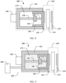
- FIG. 8 is a schematic diagram of a structure of a brake system according to an embodiment of this application.
- a brake system 200 includes a motor assembly 160 and the brake assembly 100 in any one of the foregoing embodiments.
- the motor assembly 160 is in a transmission connection to a driving piece, and the driving piece may drive, driven by the motor assembly 160, a piston 120 to move in a cylinder body 110.
- the motor assembly 160 drives the piston 120 to move in the cylinder body 110.
- the brake assembly 100 performs braking, the motor assembly 160 starts and gradually reaches a rated rotational speed of the motor assembly 160.
- the motor assembly 160 runs at a rated rotation speed for a period of time to eliminate an empty stroke. Then, when the driving piece is driven to push the piston 120 to move, the driving piece first overcomes an elastic force of an elastic piece 130, and then drive the piston 120 to move, so as to drive a friction block to clamp a braking disc for braking. When the brake assembly 100 cancels braking, a nut 140 pulls the piston 120 to reset through the elastic piece 130, so that the piston 120 is reset quickly, to drive the friction block to be detached from the brake disc. This can reduce a generated dragging torque, reduce travel resistance of a vehicle, and enhance energy saving effect of the vehicle. In addition, this solution helps reduce heat generated by a brake, so as to improve reliability and a service life of the brake, and improve vehicle safety.
- the driving piece may specifically include the nut 140 and a screw 150.
- the motor assembly 160 is in a transmission connection to the screw 150, to drive the screw 150 to rotate.
- the nut 140 is connected to the screw 150 through threads.
- the screw 150 rotates to drive the nut 140 to move in an axial direction of the screw 150.
- the nut 140 is connected to the piston 120 through the elastic piece 130, and the nut 140 may drive the piston 120 to move in the cylinder body 110.
- the motor assembly 160 drives the piston 120 to move in the cylinder body 110.
- the screw 150 and the nut 140 are cooperated to form the driving piece. In this way, structure stability is high and costs are low.
- the motor assembly 160 is in a transmission connection to the screw 150 means that the motor assembly 160 may transmit a driving force to the screw 150, or may be understood as that the motor assembly 160 may drive the screw to move through a transmission connection.
- the screw 150 may be directly connected to an output axis of the motor assembly 160, or the screw 150 may be connected to the motor assembly 160 through an intermediate structure.
- a structure like a reducer is further disposed between the motor assembly 160 and the screw 150.
- the motor assembly 160 rotates forward, and drives the nut through the screw to push the piston to move, to perform braking; or the motor assembly 160 rotates backward, and drives the nut through the screw to pull the piston to move, to cancel braking.
- braking may be canceled when the motor assembly 160 rotates forward, and braking may be performed when the motor assembly 160 rotates backward.
- the hydraulic apparatus is used for braking, although the nut does not move when braking is canceled, the elastic piece is in a stretching state between the nut and the piston, and the piston may also be pulled to move.
- the foregoing brake system further includes a brake 210.
- the brake 210 is connected to the piston 120, and the motor assembly 160 may apply a motor driving force to the brake 210 through the piston 120, to drive the brake 210 to brake.
- the forward rotation of the motor assembly 160 drives the brake to brake.
- the backward rotation of the motor assembly 160 may drive the brake to cancel braking.
- braking may be canceled when the motor assembly 160 rotates forward, and braking may be performed when the motor assembly 160 rotates backward.
- the brake system 200 has a small dragging torque. This can reduce travel resistance of the vehicle and enhance energy saving effect of the vehicle.
- the solution helps improve reliability and a service life of the brake 210, and improve vehicle safety.
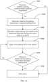
- Step S104 Apply a first parking force to the vehicle.
- Step S106 End control.
- the entire brake system 200 stops working when the pressure of the hydraulic apparatus 300 is zero, and the elastic force of the elastic piece minus the motor braking force is equal to the target parking force.
- the nut 140 and a screw 150 implement self-locking, and a position of the nut 140 is fixed, so as to ensure that the motor braking force provided by the motor assembly 160 to the brake 210 through the nut 140 remains unchanged. Therefore, even if the motor assembly 160 does not work, the brake system 200 can still control vehicle parking based on the target parking force.
- cooperation between the motor braking force and the hydraulic braking force can be coordinated, so that a braking force received by a vehicle is suitable for vehicle parking.
- Step S1021 Determine whether the parking condition meets the electric parking brake requirement; and if the parking condition meets the electric parking brake requirement, perform step S1022; or if the parking condition does not meet the electric parking brake requirement, perform step S1023.
- a current status of the vehicle is suitable for parking, and it is determined that the parking condition meets the electric parking brake requirement.
- the first requested parking force is the requested parking force.
- the parking condition does not meet the electric parking brake requirement, but the parking condition meets the external requirement, it is determined that the second requested parking force is the requested parking force.
- the vehicle may receive two parking requirements: an external requirement and an electric parking brake requirement. When there is an electric parking brake requirement, the vehicle responds to the electric parking brake requirement. If there is no electric parking brake requirement, the vehicle may respond to the external requirement.
Landscapes
- Engineering & Computer Science (AREA)
- Mechanical Engineering (AREA)
- General Engineering & Computer Science (AREA)
- Transportation (AREA)
- Braking Arrangements (AREA)
Abstract
Description
- This application relates to the field of vehicle technologies, and in particular, to a brake assembly, a brake system, a vehicle, and a brake system control method.
- When a vehicle is in use, the vehicle often needs to be braked. Vehicle parking is used as an example. With development of technologies, a brake mode based on an electric parking brake (Electrical Park Brake, EPB) emerges. A user sends an instruction to an electronic control unit by controlling a pushbutton switch, the electronic control unit controls a brake assembly, and the brake assembly drives a friction block of a brake to clamp a brake disc to perform braking, so as to implement parking. Currently, the park mode based on the EPB produces a dragging torque, increases travel resistance of a vehicle, and causes the brake to heat up.
- This application provides a brake assembly, a brake system, a vehicle, and a brake system control method, so that a friction block of a brake can be quickly separated from a brake disc. This reduces a generated dragging torque, reduces travel resistance of a vehicle, and enhances energy saving effect of the vehicle. In addition, the solutions help improve reliability and a service life of the brake, and improve vehicle safety.
- According to a first aspect, this application provides a brake assembly. The brake assembly includes a cylinder body, a piston, an elastic piece and a driving piece. The piston is mounted in an inner cavity of the cylinder body, and the piston can move in the inner cavity of the cylinder body. The piston and the inner cavity of the cylinder body form an accommodating cavity. The driving piece and the elastic piece are disposed in the accommodating cavity, and the driving piece is connected to the piston through the elastic piece. In other words, two ends of the elastic piece are respectively fixedly connected to the driving piece and the piston. The driving piece is configured to drive the piston to move in the inner cavity of the cylinder body. In an actual use process, the piston can be connected to a brake, so as to drive the brake to brake. In this solution, when braking is required, the driving piece may be enabled to push the piston to move. When braking needs to be canceled, the driving piece may be enabled to pull the piston to move. It should be noted that, when a hydraulic apparatus is used for braking, although the driving piece does not move when braking is canceled, the elastic piece is in a stretching state between the driving piece and the piston, so that the piston may also be pulled to move and reset. In conclusion, in the technical solution of this application, when braking is canceled, the elastic piece may provide a pulling force for the piston, so that the piston is reset quickly. Therefore, in this solution, the elastic piece is used to drive the piston to quickly reset, so as to drive the friction block to be detached from a brake disc in a short time, so that the brake completely cancels a braking state. This can overcome a problem of severe adhesion between the friction block and the brake disc caused by a long braking time or an excessively large braking force, and resolve a problem of a large vehicle dragging torque. This solution can help reduce a dragging torque, reduce travel resistance of a vehicle, and enhance energy saving effect of the vehicle. In addition, this solution helps reduce heat generated by the brake, improve reliability and a service life of the brake, and improve vehicle safety.
- The driving piece in this application may specifically include a screw and a nut. The screw and the nut implement a transmission connection through threads. In other words, the screw rotates to drive the nut to move in an axial direction of the screw. The screw is connected to a motor assembly. The motor assembly may drive the screw to rotate, so as to drive the nut to move, and the nut drives the piston to move through the elastic piece. In this solution, the screw and the nut are cooperated to form the driving piece. In this way, structure stability is high and costs are low.
- A specific structure of the elastic piece in the foregoing technical solution is not limited in this application, provided that the elastic piece is elastic. For example, the elastic piece may be a spring or a rubber elastic piece.
- In addition, a specific mounting manner of the elastic piece in the foregoing technical solution is not limited in this application. For example, one end of the elastic piece may be directly fixedly connected to the driving piece, and the other end may be directly connected to the piston through driving. Alternatively, a connection may be implemented in cooperation with another structure. For example, a side that is of the driving piece and that faces the piston has a first non-flat end face, a side that is of the piston and that faces the driving piece has a second non-flat end face, and the elastic piece is connected between the first non-flat end face and the second non-flat end face. The following enumerates specific connection manners of several elastic pieces.
- The driving piece may have a first limiting protrusion, and the elastic piece is sleeved on an outer side of the first limiting protrusion. In this case, the first limiting protrusion can improve mounting stability of the elastic piece, and can guide the elastic piece to a specific extent, so that the elastic piece is not easily bent. Alternatively, the driving piece may have a first limiting groove, and the elastic piece is disposed in the first limiting groove. Therefore, the first limiting groove can improve mounting stability of the elastic piece, and can guide the elastic piece to a specific extent, so that the elastic piece is not easily bent. Similarly, for one side of the piston, the piston may also have a second limiting protrusion or a second limiting groove. When the piston has the second limiting protrusion, the elastic piece is sleeved on an outer side of the second limiting protrusion. In this case, the second limiting protrusion can improve mounting stability of the elastic piece, and can guide the elastic piece to a specific extent, so that the elastic piece is not easily bent. When the piston has the second limiting groove, the elastic piece is disposed in the second limiting groove. Therefore, the second limiting groove can improve mounting stability of the elastic piece, and can guide the elastic piece to a specific extent, so that the elastic piece is not easily bent.
- In a specific technical solution, the driving piece may have a first limiting protrusion, and the piston may have a second limiting protrusion. Alternatively, the driving piece has a first limiting groove, and the piston has a second limiting groove. Alternatively, the driving piece may have a first limiting protrusion, and the piston may have a second limiting groove. In this case, when the elastic piece shrinks, the first limiting protrusion may extend into the second limiting groove. This helps reduce a size of the elastic piece, so as to reduce a size of the entire brake assembly. Similarly, when the driving piece has a first limiting groove, the piston has a second limiting protrusion, and the elastic piece shrinks, the second limiting protrusion may extend into the first limiting groove. This also helps reduce a size of the elastic piece, so as to reduce a size of the entire brake assembly.
- In another technical solution, a first limiting piece may be further mounted on the driving piece, and the first limiting piece is pivotally mounted on the driving piece. In other words, the first limiting piece may rotate relative to the driving piece, but cannot move. A second limiting piece is mounted on the piston, and the second limiting piece is pivotally mounted on the piston. Similarly, the second limiting piece may rotate relative to the piston, but cannot move. The elastic piece is disposed between the first limiting piece and the second limiting piece, and the elastic piece can rotate relative to the piston and the nut. This helps improve flexibility of the elastic piece and reduce a possible twist stress generated in the elastic piece.
- The driving piece may further have a first mounting boss for mounting the first limiting piece and the second limiting piece, and the first limiting piece is pivotally mounted on the first mounting boss. The piston has a second mounting boss, and the second limiting piece is pivotally mounted on the second mounting boss.
- According to a second aspect, this application further provides a brake system. The brake system includes a cylinder body, a piston, an elastic piece, a driving piece, and a motor assembly. The piston is mounted in an inner cavity of the cylinder body, so that the piston and the inner cavity of the cylinder body form an accommodating cavity. The driving piece and the elastic piece are disposed in the accommodating cavity, and the driving piece is connected to the piston through the elastic piece. The motor assembly is in a transmission connection to the driving piece. In other words, the motor assembly may drive the driving piece to move, and drive, through the elastic piece, the piston to move. In an actual use process, the piston can be connected to a brake, so as to drive the brake to brake. In this solution, when the motor assembly rotates forward, the piston is pushed to move through the driving piece, to perform braking. When the motor assembly rotates backward, the piston is pulled to move through the driving piece, to cancel braking. Certainly, alternatively, braking may be canceled when the motor assembly rotates forward, and braking may be performed when the motor assembly rotates backward. It should be noted that, when a hydraulic apparatus is used for braking, although the driving piece does not move when braking is canceled, the elastic piece is in a stretching state between the driving piece and the piston, so that the piston may also be pulled to move and reset. In conclusion, in the technical solution of this application, when braking is canceled, the elastic piece may provide a pulling force for the piston, so that the piston is reset quickly. Therefore, the solution can help reduce a dragging torque, reduce travel resistance of a vehicle, and enhance energy saving effect of the vehicle. In addition, this solution helps reduce heat generated by the brake, improve reliability and a service life of the brake, and improve vehicle safety.
- The driving piece in the technical solution of this application may specifically include a screw and a nut. The screw and the nut implement a transmission connection through threads. In other words, the screw rotates to drive the nut to move in an axial direction of the screw. The screw is connected to the motor assembly. The motor assembly may drive the screw to rotate, so as to drive the nut to move, and the nut drives the piston to move through the elastic piece. In this solution, the screw and the nut are cooperated to form the driving piece. In this way, structure stability is high and costs are low.
- A specific structure of the elastic piece in the foregoing technical solution is not limited in this application, provided that the elastic piece is elastic. For example, the elastic piece may be a spring or a rubber elastic piece.
- In addition, a specific mounting manner of the elastic piece in the foregoing technical solution is not limited in this application. For example, one end of the elastic piece may be directly fixedly connected to the driving piece, and the other end may be directly connected to the piston through driving. Alternatively, a connection may be implemented in cooperation with another structure. The following enumerates specific connection manners of several elastic pieces.
- The driving piece may have a first limiting protrusion, and the elastic piece is sleeved on an outer side of the first limiting protrusion. In this case, the first limiting protrusion can improve mounting stability of the elastic piece, and can guide the elastic piece to a specific extent, so that the elastic piece is not easily bent. Alternatively, the driving piece may have a first limiting groove, and the elastic piece is disposed in the first limiting groove. Therefore, the first limiting groove can improve mounting stability of the elastic piece, and can guide the elastic piece to a specific extent, so that the elastic piece is not easily bent. Similarly, for one side of the piston, the piston may also have a second limiting protrusion or a second limiting groove. When the piston has the second limiting protrusion, the elastic piece is sleeved on an outer side of the second limiting protrusion. In this case, the second limiting protrusion can improve mounting stability of the elastic piece, and can guide the elastic piece to a specific extent, so that the elastic piece is not easily bent. When the piston has the second limiting groove, the elastic piece is disposed in the second limiting groove. Therefore, the second limiting groove can improve mounting stability of the elastic piece, and can guide the elastic piece to a specific extent, so that the elastic piece is not easily bent.
- In a specific technical solution, the driving piece may have a first limiting protrusion, and the piston may have a second limiting protrusion. Alternatively, the driving piece has a first limiting groove, and the piston has a second limiting groove. Alternatively, the driving piece may have a first limiting protrusion, and the piston may have a second limiting groove. In this case, when the elastic piece shrinks, the first limiting protrusion may extend into the second limiting groove. This helps reduce a size of the elastic piece, so as to reduce a size of the entire brake system. Similarly, when the driving piece has a first limiting groove, the piston has a second limiting protrusion, and the elastic piece shrinks, the second limiting protrusion may extend into the first limiting groove. This also helps reduce a size of the elastic piece, so as to reduce a size of the entire brake system.
- In another technical solution, a first limiting piece may be further mounted on the driving piece, and the first limiting piece is pivotally mounted on the driving piece. In other words, the first limiting piece may rotate relative to the driving piece, but cannot move. A second limiting piece is mounted on the piston, and the second limiting piece is pivotally mounted on the piston. Similarly, the second limiting piece may rotate relative to the piston, but cannot move. The elastic piece is disposed between the first limiting piece and the second limiting piece, and the elastic piece can rotate relative to the piston and the nut. This helps improve flexibility of the elastic piece and reduce a possible twist stress generated in the elastic piece.
- The driving piece may further have a first mounting boss for mounting the first limiting piece and the second limiting piece, and the first limiting piece is pivotally mounted on the first mounting boss. The piston has a second mounting boss, and the second limiting piece is pivotally mounted on the second mounting boss.
- The brake system may further include a brake. The brake is connected to the piston in the brake assembly. In this case, when the driving piece drives the piston to move under driving of the motor assembly, the motor assembly may apply a motor braking force to the brake, to drive the brake to brake. Certainly, for example, the forward rotation of the motor assembly drives the brake to brake. In this case, the backward rotation of the motor assembly may drive the brake to cancel braking. In this solution, because the elastic piece can drive the piston to reset quickly when braking is canceled, the brake system has a small dragging torque. This can reduce travel resistance of the vehicle and enhance energy saving effect of the vehicle. In addition, the solution helps improve reliability and a service life of the brake, and improve vehicle safety.
- In a specific technical solution, the brake may include a brake disc, a first friction block, and a second friction block. The first friction block is in a transmission connection to the second friction block, and the first friction block and the second friction block can move close to each other or move away from each other. In other words, when the first friction block is driven to move, the second friction block moves simultaneously, and the first friction block and the second friction block move in opposite directions. Alternatively, when the second friction block is driven to move, the first friction block moves simultaneously, and the first friction block and the second friction block move in opposite directions. The brake disc is disposed between the first friction block and the second friction block, and in a process of moving of the first friction block and the second friction block, the brake disc is clamped or the brake disc is released. Specifically, the first friction block is connected to the piston, and the driving piece drives the piston to move, to drive the first friction block and the second friction block to clamp or release the brake disc. When braking is cancelled, the driving piece drives the piston to reset through the elastic piece, and the piston drives a friction block to be detached from the brake disc. This can reduce adhesion between the friction block and the brake disc.
- The brake system may further include a hydraulic apparatus, and the hydraulic apparatus is connected to the accommodating cavity formed by the cylinder body and the piston, so that the hydraulic apparatus may inject or extract liquid into the accommodating cavity, so as to drive the piston to move. In other words, the hydraulic apparatus applies a hydraulic braking force to the brake through the piston, and drives the brake to brake. In this solution, the brake system may perform braking in two manners, and application scenarios are rich. In addition, after the hydraulic apparatus is used for braking, when braking is canceled, the elastic piece can still drive the piston to quickly reset. This can reduce a dragging torque and situations of a hydraulic pump of the hydraulic apparatus being stuck.
- The brake system may further include an electronic control unit. The electronic control unit is in a signal connection to the motor assembly, and the electronic control unit controls the motor assembly to rotate forward, rotate backward, or stop rotating. In this solution, the electronic control unit may be used to control braking of the vehicle. Specifically, the electronic control unit may be started by using a manual control button, to control braking of the vehicle. The electronic control unit can also be connected to a controller to intelligently determine a current status of the vehicle for braking. For example, this is applied to an autonomous driving mode.
- When the electronic control unit may be used in a vehicle parking scenario, the electronic control unit is configured to: determine whether a parking condition meets a parking requirement; determine, based on the parking requirement, a requested parking force when the parking condition meets the parking requirement; or when the parking condition does not meet the parking requirement, end control; calculate a target parking force based on the determined requested parking force and the status of the vehicle; and apply a first parking force to the vehicle until the first parking force meets the target parking force. In this solution, the target parking force may be first determined, so that an excessively large parking force can be prevented, and a probability of adhesion between the friction block and the brake disc can be reduced.
- When the brake system further includes the hydraulic apparatus, and the electronic control unit is further in a signal connection to the hydraulic apparatus, applying the first parking force to the vehicle includes:
determining whether the hydraulic apparatus participates in parking braking; and if the hydraulic apparatus participates in parking braking, controlling the hydraulic apparatus to apply a hydraulic braking force, and controlling the motor assembly to apply a motor braking force, where a combined force of the hydraulic braking force and the motor braking force is the first parking force, that is, the first parking force includes the hydraulic braking force and the motor braking force; or if the hydraulic apparatus does not participate in parking braking, controlling the motor assembly to apply a motor braking force, where the motor braking force is the first parking force. In this solution, the first parking force to which the brake is subject may be controlled as the target parking force with reference to braking forces separately provided by the hydraulic apparatus and the motor assembly, so as to avoid a case in which an excessively large parking force is caused because the hydraulic apparatus and the motor assembly are separately controlled. - In a specific technical solution, the parking requirement includes an external requirement and an electric parking brake requirement, and the electronic control unit is configured to: determine whether the parking condition meets the electric parking brake requirement; and if the parking condition meets the electric parking brake requirement, determine that a first requested parking force requested in the electric parking brake requirement is the requested parking force; or if the parking condition does not meet the electric parking brake requirement, determine whether the parking condition meets the external requirement; and if the parking condition meets the external requirement, determine that a second requested parking force requested in the external requirement is the requested parking force. In this solution, the vehicle may receive two parking requirements: an external requirement and an electric parking brake requirement. When there is an electric parking brake requirement, the vehicle responds to the electric parking brake requirement. If there is no electric parking brake requirement, the vehicle may respond to the external requirement. The external requirement includes a parking request from another component other than the electronic control unit, and the electric parking brake requirement includes a parking request triggered by a driver by using the electronic control unit.
- The status of the vehicle may specifically include one or more of a ramp on which the vehicle is located, a mass of the vehicle, whether a trailer is attached to the vehicle, and a temperature of the brake disc. In other words, when calculating the target parking force, the electronic control unit may calculate the target parking force of the vehicle based on the requested parking force, the ramp on which the vehicle is located, the mass of the vehicle, whether the trailer is attached to the vehicle, and the temperature of the brake disc. In this way, the vehicle can be reliably parked, and a parking force is not excessively large.
- According to a third aspect, this application further provides a vehicle. The vehicle includes the brake assembly in the first aspect, and further includes wheels connected to the brake assembly, and the brake assembly may brake the wheels. Specifically, the brake assembly may be directly connected to the wheels, or may be connected the wheels through an intermediate structure, provided that the brake assembly can brake the wheels. The brake assembly in this solution can drive a friction block of a brake to be quickly separated from a brake disc. This reduces a generated dragging torque, reduces travel resistance of the vehicle, and enhances energy saving effect of the vehicle. In addition, the solution helps improve reliability and a service life of the brake, and improve vehicle safety.
- According to a fourth aspect, this application further provides a vehicle. The vehicle includes the brake system in the second aspect, and further includes wheels connected to the brake system, and the brake system may brake the wheels. Specifically, the brake system may be directly connected to the wheels, or may be connected the wheels through an intermediate structure, provided that the brake system can brake the wheels. The brake system in this solution can drive a friction block of a brake to be quickly separated from a brake disc. This reduces a generated dragging torque, reduces travel resistance of the vehicle, and enhances energy saving effect of the vehicle. In addition, the solution helps improve reliability and a service life of the brake, and improve vehicle safety.
- According to a fifth aspect, this application further provides a control method. The control method is specifically applied to the brake system in the second aspect. The control method specifically includes: determining, based on a parking requirement, a requested parking force when a parking condition meets the parking requirement; calculating a target parking force based on the determined requested parking force and a status of a vehicle; and applying a first parking force to the vehicle until the first parking force meets the target parking force.
- When the brake system further includes a hydraulic apparatus, the applying a first parking force to the vehicle specifically includes: determining whether the hydraulic apparatus participates in parking braking; and if the hydraulic apparatus participates in parking braking, controlling the hydraulic apparatus to apply a hydraulic braking force, and controlling a motor assembly to apply a motor braking force, where a combined force of the hydraulic braking force and the motor braking force is the first parking force, that is, the first parking force includes the hydraulic braking force and the motor braking force; or if the hydraulic apparatus does not participate in parking braking, controlling a motor assembly to apply a motor braking force, where the motor braking force is the first parking force. In other words, the first parking force to which a brake is subject may be controlled as the target parking force with reference to braking forces separately provided by the hydraulic apparatus and the motor assembly, to avoid an excessively large parking force caused due to separate control.
- The parking requirement specifically includes an external requirement and an electric parking brake requirement. The determining, based on a parking requirement, a requested parking force when a parking condition meets the parking requirement includes: determining whether the parking condition meets the electric parking brake requirement; and if the parking condition meets the electric parking brake requirement, determining that a first requested parking force requested in the electric parking brake requirement is the requested parking force; or if the parking condition does not meet the electric parking brake requirement, determining whether the parking condition meets the external requirement; and if the parking condition meets the external requirement, determining that a second requested parking force requested in the external requirement is the requested parking force. In this solution, the vehicle may receive two parking requirements: an external requirement and an electric parking brake requirement. When there is an electric parking brake requirement, the vehicle responds to the electric parking brake requirement. If there is no electric parking brake requirement, the vehicle may respond to the external requirement. The external requirement includes a parking request from another component other than an electronic control unit, and the electric parking brake requirement includes a parking request triggered by a driver by using the electronic control unit.
- The status of the vehicle may specifically include one or more of a ramp on which the vehicle is located, a mass of the vehicle, whether a trailer is attached to the vehicle, and a temperature of a brake disc. In other words, when calculating the target parking force, the electronic control unit may calculate the target parking force of the vehicle based on the requested parking force, the ramp on which the vehicle is located, the mass of the vehicle, whether the trailer is attached to the vehicle, and the temperature of the brake disc. In this way, the vehicle can be reliably parked, and a parking force is not excessively large.
-
-
FIG. 1 is a schematic diagram of a structure of a brake assembly according to an embodiment of this application; -
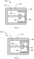
FIG. 2 is a schematic diagram of another structure of a brake assembly according to an embodiment of this application; -
FIG. 3 is a schematic diagram of another structure of a brake assembly according to an embodiment of this application; -
FIG. 4 is a schematic diagram of another structure of a brake assembly according to an embodiment of this application; -
FIG. 5 is a schematic diagram of another structure of a brake assembly according to an embodiment of this application; -
FIG. 6 is a schematic diagram of another structure of a brake assembly according to an embodiment of this application; -
FIG. 7 is a schematic diagram of another structure of a brake assembly according to an embodiment of this application; -
FIG. 8 is a schematic diagram of a structure of a brake system according to an embodiment of this application; -
FIG. 9 is a schematic diagram of another structure of a brake system according to an embodiment of this application; -
FIG. 10 is a schematic diagram of another structure of a brake system according to an embodiment of this application; -
FIG. 11 is a schematic diagram of another structure of a brake system according to an embodiment of this application; -
FIG. 12 is a control flowchart of a brake system according to an embodiment of this application; -
FIG. 13 is a schematic diagram of a working condition of a vehicle in a working process according to an embodiment of this application; -
FIG. 14 is another control flowchart of a brake system according to an embodiment of this application; -
FIG. 15 is a schematic diagram of a structure of a vehicle according to an embodiment of this application; and -
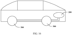
FIG. 16 is a schematic diagram of another structure of a vehicle according to an embodiment of this application. -
- 100: brake assembly; 110: cylinder body;
- 120: piston; 121: second limiting protrusion;
- 122: second limiting groove; 123: second limiting piece;
- 124: second mounting boss; 130: elastic piece;
- 140: nut; 141: first limiting protrusion;
- 142: first limiting groove; 143: first limiting piece;
- 144: first mounting boss; 150: screw;
- 160: motor assembly; 170: accommodating cavity;
- 200: brake system; 210: brake;
- 211: brake disc; 212: first friction block;
- 213: second friction block; 300: hydraulic apparatus;
- 400: electronic control unit; 500: wheel.
- To facilitate understanding of a brake assembly, a brake system, a vehicle, and a brake assembly control method provided in embodiments of this application, the following describes an application scenario of the brake assembly, the brake system, the vehicle, and the brake assembly control method. The brake system is an important part of the vehicle and plays an important role in safety and performance of the vehicle. At present, when a car is braked, a brake assembly is used to drive friction plates to clamp a brake disc for braking, and when braking is stopped, the friction plates may be stuck to the brake disc. When the friction plates are stuck to the brake disc, the car is in a braking state. This causes a dragging torque and increases travel resistance. In addition, it is easy to cause a brake to heat. In this way, reliability and a service life of the brake are reduced, and the vehicle has a safety risk.
- The following describes in detail embodiments of this application with reference to accompanying drawings. Terms used in the following embodiments are merely intended to describe specific embodiments, but are not intended to limit this application. The terms "one", "a", and "this" of singular forms used in this specification and the appended claims of this application are also intended to include expressions such as "one or more", unless otherwise specified in the context clearly.
- Reference to "an embodiment", "a specific embodiment", or the like described in this specification indicates that one or more embodiments of this application include a specific feature, structure, or characteristic described with reference to embodiments. Terms "include", "contain", "have", and variants of the terms all mean "include but are not limited to", unless otherwise specifically emphasized in other ways.
-
FIG. 1 is a schematic diagram of a structure of a brake assembly according to an embodiment of this application. As shown inFIG. 1 , abrake assembly 100 includes acylinder body 110, apiston 120, anelastic piece 130, and a driving piece. Thepiston 120 is mounted in an inner cavity of thecylinder body 110, so that thepiston 120 and the inner cavity of thecylinder body 110 form anaccommodating cavity 170. The driving piece and theelastic piece 130 are disposed in theaccommodating cavity 170. The driving piece is connected to thepiston 120 through theelastic piece 130, and the driving piece is configured to drive thepiston 120 to move in thecylinder body 110. The driving piece is connected to thepiston 120 through theelastic piece 130. In other words, theelastic piece 130 is connected between the driving piece and thepiston 120, one end of theelastic piece 130 is connected to the driving piece, and the other end is connected to thepiston 120. When thebrake assembly 100 performs braking, the driving piece pushes thepiston 120 to move. The driving piece first overcomes an elastic force of theelastic piece 130, and then drives thepiston 120 to move, to drive a friction block to clamp a braking disc for braking. When thebrake assembly 100 cancels braking, the driving piece pulls thepiston 120 through theelastic piece 130 to reset, so that thepiston 120 is reset quickly, to drive the friction block to be detached from the brake disc. In this solution, the elastic piece is used to drive the piston to quickly reset, so as to drive the friction block to be detached from the brake disc in a short time, so that a brake completely cancels a braking state. This can overcome a problem of severe adhesion between the friction block and the brake disc caused by a long braking time or an excessively large braking force, and resolve a problem of a large vehicle dragging torque. Therefore, this solution can help reduce a generated dragging torque, reduce travel resistance of a vehicle, and enhance energy saving effect of the vehicle. In addition, this solution helps reduce heat generated by the brake, so as to improve reliability and a service life of the brake, and improve vehicle safety. - The driving piece may specifically include a
nut 140 and ascrew 150, and thenut 140 is connected to thescrew 150 through threads. Thescrew 150 rotates to drive thenut 140 to move in an axial direction of thescrew 150. Thenut 140 is connected to thepiston 120 through theelastic piece 130, so that thenut 140 may drive thepiston 120 to move in thecylinder body 110. In this solution, thescrew 150 and thenut 140 are cooperated to form the driving piece. In this way, structure stability is high and costs are low. In a specific embodiment, a specific structure of theelastic piece 130 is not limited. For example, theelastic piece 130 may be a spring, and the spring may be a straight-line spring, a gradually changing spring, a sheet spring, or the like. Alternatively, theelastic piece 130 may be another elastic piece, provided that thenut 140 can be elastically connected to thepiston 120. In an optional design, a tensile force F that can be implemented by theelastic piece 130 in this embodiment of this application is approximately F=10N to 15N, where N is a force unit Newton. A deformation amount x of theelastic piece 130 is about 1 mm. According to Hooke's law, a spring constant K of a straight-line spring meets: K=F/x=10000 N/m to 15000N/m, so as to facilitate miniaturization of thebrake assembly 100. - In a specific technical solution, a material of the foregoing elastic piece is compatible with a brake fluid of a hydraulic apparatus connected to the brake assembly, so as to improve a service life of the elastic piece.
- In some possible implementations, when the
piston 120 is mounted on thecylinder body 110, an outer circumferential surface of thepiston 120 may be closely attached to an inner circumferential surface of thecylinder body 110, so that a sealing cavity is formed between thepiston 120 and the cylinder body. It should be noted that the sealing cavity herein mainly means that thepiston 120 and thecylinder body 110 are connected in a sealed manner, and are in a sealed state in an actual working process, and the cylinder body may be provided with an opening. For example, the sealing cavity may also be connected to the hydraulic apparatus, so that the hydraulic apparatus can also work in the sealing cavity. In this case, thecylinder body 110 definitely includes an opening connected to the hydraulic apparatus. However, after the hydraulic apparatus is connected to the foregoing sealing cavity, the sealing cavity between thepiston 120 and thecylinder body 110 is in the sealed state. Alternatively, the driving piece is disposed in the sealing cavity. A corresponding opening is also provided in thecylinder body 110 for mounting the driving piece. However, after the driving piece is mounted, the sealing cavity may be in the sealed state. These are not described one by one in this application. In addition, a sealing component may be disposed between thepiston 120 and thecylinder body 110, to form the sealing cavity. More specifically, the sealing component may be disposed between the outer circumferential surface of the piston and the inner circumferential surface of the cylinder body, to perform a sealing function. In an optional embodiment, the sealing component may include a plurality of sealing rings, and the plurality of sealing rings are disposed in parallel on a peripheral surface of the piston, to achieve better sealing effect. - Two ends of the
elastic piece 130 are respectively fixedly connected to the driving piece and thepiston 120 along a moving direction of thepiston 120. However, a specific connection structure is not limited. For example, one end of the elastic piece may be directly fixedly connected to the driving piece, and the other end may be directly connected to the piston through driving. Alternatively, a connection may be implemented in cooperation with another structure. For example, a side that is of the driving piece and that faces the piston has a first non-flat end face, a side that is of the piston and that faces the driving piece has a second non-flat end face, and the elastic piece is connected between the first non-flat end face and the second non-flat end face. Specifically, the driving piece may have a first limitingprotrusion 141 or a first limitinggroove 142, and theelastic piece 130 is fixedly connected to the first limitingprotrusion 141 or the first limitinggroove 142 of the driving piece. Alternatively, thepiston 120 has a second limitingprotrusion 121 or a second limitinggroove 122, and theelastic piece 130 is fixedly connected to the second limitingprotrusion 121 or the second limitinggroove 122 of thepiston 120. That a part "has" a structure means that a structure may be directly prepared on the part. The structure and the part may be an integrated structure, for example, an integrally formed structure, or mounted through a fastener. For example, the driving piece has the first limiting protrusion. The first limiting protrusion and the driving piece may be an integrally formed structure, or the first limiting protrusion and the driving piece are fixedly connected to form an integrally formed structure through welding, screw connection, bonding, or the like. - The following uses an example in which the driving piece includes the
nut 140 and thescrew 150 to enumerate several embodiments to describe possible implementations of disposing theelastic piece 130. -
FIG. 2 is a schematic diagram of another structure of a brake assembly according to an embodiment of this application. As shown inFIG. 2 , in an embodiment, thenut 140 has the first limitingprotrusion 141, and the first limitingprotrusion 141 is located on a side that is of thenut 140 and that faces thepiston 120. Thepiston 120 has the second limitingprotrusion 121, and the second limitingprotrusion 121 is located on a side that is of thepiston 120 and that faces thenut 140. The two ends of theelastic piece 130 are respectively sleeved on an outer side of the first limitingprotrusion 141 and an outer side of the second limitingprotrusion 121. In this solution, the first limitingprotrusion 141 and the second limitingprotrusion 121 can limit theelastic piece 130, and improve stability of theelastic piece 130, so that theelastic piece 130 deforms in the axial direction of thescrew 150, and a problem like bending is not easily caused. The axial direction of thescrew 150 is also a moving direction of thepiston 120 and thenut 140. - It should be noted that a specific form of the first limiting
protrusion 141 is not limited, provided that theelastic piece 130 can be sleeved on the outer side of the first limiting protrusion. For example, in the embodiment shown inFIG. 2 , a surface that is of thenut 140 and that faces thepiston 120 has a protruding first limitingprotrusion 141. In other words, a surface of a part that is of the nut and that does not have the first limitingprotrusion 141 is lower than the first limitingprotrusion 141. Alternatively, the nut may have a gap on a periphery of the first limitingprotrusion 141, so that the elastic piece can extend into the gap. A specific form of the second limitingprotrusion 121 is not limited, provided that theelastic piece 130 can be sleeved on the outer side of the second limitingprotrusion 121. For example, in the embodiment shown inFIG. 2 , a surface that is of thepiston 120 and that faces thenut 140 has a protruding second limitingprotrusion 121. In other words, a surface of a part that is of thepiston 120 and that does not have the second limitingprotrusion 121 is lower than the second limitingprotrusion 121. Alternatively, thepiston 120 may further have a gap on a periphery of the second limitingprotrusion 121, so that theelastic piece 130 can extend into the gap. -
FIG. 3 is a schematic diagram of another structure of a brake assembly according to an embodiment of this application. As shown inFIG. 3 , in an embodiment, thenut 140 has the first limitingprotrusion 141, and the first limitingprotrusion 141 is located on the side that is of thenut 140 and that faces thepiston 120. Thepiston 120 has the second limitinggroove 122, and the second limitinggroove 122 is located on the side that is of thepiston 120 and that faces thenut 140. One end of theelastic piece 130 is sleeved on the outer side of the first limitingprotrusion 141, and the other end is located inside the second limitinggroove 122. When the other end of theelastic piece 130 is located in the second limitinggroove 122, theelastic piece 130 may be limited from a periphery of theelastic piece 130 by using the second limitinggroove 122. In this solution, the first limitingprotrusion 141 and the second limitinggroove 122 can limit theelastic piece 130, and improve stability of theelastic piece 130, so that theelastic piece 130 deforms in the axial direction of thescrew 150, and a problem like bending is not easily caused. The axial direction of thescrew 150 is also the moving direction of thepiston 120 and thenut 140. In addition, in this solution, when thenut 140 pushes thepiston 120 to move, thenut 140 approaches thepiston 120. In this case, the first limitingprotrusion 141 may extend into the second limitinggroove 122, so that a distance between thenut 140 and thepiston 120 is short. This facilitates miniaturization of thebrake assembly 100. - It should be noted that a specific form of the second limiting
groove 122 is not limited either. For example, in the embodiment shown inFIG. 3 , a protruding groove wall is prepared on the surface that is of thepiston 120 and that faces thenut 140, to form the second limitinggroove 122. Alternatively, in another embodiment, a material may be removed from the surface that is of thepiston 120 and that faces thenut 140 to dig the second limitinggroove 122. -
FIG. 4 is a schematic diagram of another structure of a brake assembly according to an embodiment of this application. As shown inFIG. 4 , in an embodiment, thenut 140 has the first limitinggroove 142, and the first limitinggroove 142 is located on the side that is of thenut 140 and that faces thepiston 120. Thepiston 120 has the second limitingprotrusion 121, and the second limitingprotrusion 121 is located on the side that is of thepiston 120 and that faces thenut 140. One end of theelastic piece 130 is sleeved inside the first limitinggroove 142, and the other end is sleeved outside the second limitingprotrusion 121. In this solution, the first limitinggroove 142 and the second limitingprotrusion 121 can limit theelastic piece 130, and improve stability of theelastic piece 130, so that theelastic piece 130 deforms in the axial direction of thescrew 150, and a problem like bending is not easily caused. The axial direction of thescrew 150 is also the moving direction of thepiston 120 and thenut 140. In addition, in this solution, when thenut 140 pushes thepiston 120 to move, thenut 140 approaches thepiston 120. In this case, the second limitingprotrusion 121 may extend into the first limitinggroove 142, so that the distance between thenut 140 and thepiston 120 is short. This facilitates miniaturization of thebrake assembly 100. - It should be noted that a specific form of the first limiting
groove 142 is not limited either. For example, in the embodiment shown inFIG. 4 , a protruding groove wall is prepared on the surface that is of thenut 140 and that faces thepiston 120, to form the second limitinggroove 122. Alternatively, in another embodiment, a material may be removed from the surface that is of thenut 140 and that faces thepiston 120 to dig the second limitinggroove 122. -
FIG. 5 is a schematic diagram of another structure of a brake assembly according to an embodiment of this application. As shown inFIG. 5 , in an embodiment, thenut 140 has the first limitinggroove 142, and the first limitinggroove 142 is located on the side that is of thenut 140 and that faces thepiston 120. Thepiston 120 has the second limitinggroove 122, and the second limitinggroove 122 is located on the side that is of thepiston 120 and that faces thenut 140. The two ends of theelastic piece 130 are respectively disposed inside the first limitinggroove 142 and inside the second limitinggroove 122. In this solution, the first limitinggroove 142 and the second limitinggroove 122 can limit theelastic piece 130, and improve stability of theelastic piece 130, so that theelastic piece 130 deforms in the axial direction of thescrew 150, and a problem like bending is not easily caused. -
FIG. 6 is a schematic diagram of another structure of a brake assembly according to an embodiment of this application. As shown inFIG. 6 , in an embodiment, a first limitingpiece 143 is mounted on thenut 140, and the first limitingpiece 143 is located on the side that is of thenut 140 and that faces thepiston 120. In addition, the first limitingpiece 143 is pivotally mounted on thenut 140, and an extension direction of a pivot is consistent with an extension direction of theelastic piece 130, that is, consistent with a direction of thenut 140 facing thepiston 120. Therefore, the first limitingpiece 143 may rotate around an axial direction of theelastic piece 130. Thepiston 120 has a second limitingpiece 123, and the second limitingpiece 123 is located on the side that is of thepiston 120 and that faces thenut 140. The second limitingpiece 123 is pivotally mounted on thepiston 120, and an extension direction of a pivot is consistent with the extension direction of theelastic piece 130, that is, consistent with the direction of thenut 140 facing thepiston 120. Therefore, the second limitingpiece 123 may rotate around the axial direction of theelastic piece 130. Theelastic piece 130 is mounted between the first limitingpiece 143 and the second limitingpiece 123. In this solution, both the first limitingpiece 143 and the second limitingpiece 123 are rotatably mounted, and theelastic piece 130 may rotate, so as to reduce structural limitations of thenut 140 and thepiston 120 along a circumferential direction of thescrew 150, reduce a possible twist stress generated in the elastic piece, and improve flexibility of the elastic piece. - It should be noted that, that the first limiting
piece 143 is mounted on thenut 140 means that the first limitingpiece 143 is connected to thenut 140 in a mounting manner, and specifically, is mounted on thenut 140 in a pivot manner. Similarly, that the second limitingpiece 123 is mounted on thepiston 120 means that the second limitingpiece 123 is connected to thepiston 120 in a mounting manner, and specifically, is mounted on thepiston 120 in a pivot manner. - Specific mounting forms of the first limiting
piece 143 and the second limitingpiece 123 are not limited in this application either. For example,FIG. 7 is a schematic diagram of another structure of a brake assembly according to an embodiment of this application. As shown inFIG. 7 , in another embodiment, thenut 140 has a first mountingboss 144, and the first limitingpiece 143 is pivotally mounted on the first mountingboss 144. Thepiston 120 has a second mountingboss 124, and the second limitingpiece 123 is pivotally mounted on the second mountingboss 124. Alternatively, only thenut 140 may be provided with the first mountingboss 144, and thepiston 120 does not have the second mountingboss 124. Alternatively, only thepiston 120 may have the second mountingboss 124, and thenut 140 does not have the first mountingboss 144. - This application further provides a brake system. The following describes the brake system in embodiments of this application by using specific embodiments with reference to the accompanying drawings.
FIG. 8 is a schematic diagram of a structure of a brake system according to an embodiment of this application. As shown inFIG. 8 , abrake system 200 includes amotor assembly 160 and thebrake assembly 100 in any one of the foregoing embodiments. Themotor assembly 160 is in a transmission connection to a driving piece, and the driving piece may drive, driven by themotor assembly 160, apiston 120 to move in acylinder body 110. In other words, themotor assembly 160 drives thepiston 120 to move in thecylinder body 110. When thebrake assembly 100 performs braking, themotor assembly 160 starts and gradually reaches a rated rotational speed of themotor assembly 160. Themotor assembly 160 runs at a rated rotation speed for a period of time to eliminate an empty stroke. Then, when the driving piece is driven to push thepiston 120 to move, the driving piece first overcomes an elastic force of anelastic piece 130, and then drive thepiston 120 to move, so as to drive a friction block to clamp a braking disc for braking. When thebrake assembly 100 cancels braking, anut 140 pulls thepiston 120 to reset through theelastic piece 130, so that thepiston 120 is reset quickly, to drive the friction block to be detached from the brake disc. This can reduce a generated dragging torque, reduce travel resistance of a vehicle, and enhance energy saving effect of the vehicle. In addition, this solution helps reduce heat generated by a brake, so as to improve reliability and a service life of the brake, and improve vehicle safety. - The driving piece may specifically include the
nut 140 and ascrew 150. Themotor assembly 160 is in a transmission connection to thescrew 150, to drive thescrew 150 to rotate. Thenut 140 is connected to thescrew 150 through threads. Thescrew 150 rotates to drive thenut 140 to move in an axial direction of thescrew 150. Thenut 140 is connected to thepiston 120 through theelastic piece 130, and thenut 140 may drive thepiston 120 to move in thecylinder body 110. In other words, themotor assembly 160 drives thepiston 120 to move in thecylinder body 110. In this solution, thescrew 150 and thenut 140 are cooperated to form the driving piece. In this way, structure stability is high and costs are low. - It should be noted that, that the
motor assembly 160 is in a transmission connection to thescrew 150 means that themotor assembly 160 may transmit a driving force to thescrew 150, or may be understood as that themotor assembly 160 may drive the screw to move through a transmission connection. In a specific implementation, thescrew 150 may be directly connected to an output axis of themotor assembly 160, or thescrew 150 may be connected to themotor assembly 160 through an intermediate structure. For example, a structure like a reducer is further disposed between themotor assembly 160 and thescrew 150. In addition, it may be considered that themotor assembly 160 rotates forward, and drives the nut through the screw to push the piston to move, to perform braking; or themotor assembly 160 rotates backward, and drives the nut through the screw to pull the piston to move, to cancel braking. Certainly, alternatively, braking may be canceled when themotor assembly 160 rotates forward, and braking may be performed when themotor assembly 160 rotates backward. It should be noted that, when the hydraulic apparatus is used for braking, although the nut does not move when braking is canceled, the elastic piece is in a stretching state between the nut and the piston, and the piston may also be pulled to move. - Still refer to
FIG. 8 . In a specific embodiment, the foregoing brake system further includes abrake 210. Thebrake 210 is connected to thepiston 120, and themotor assembly 160 may apply a motor driving force to thebrake 210 through thepiston 120, to drive thebrake 210 to brake. For example, the forward rotation of themotor assembly 160 drives the brake to brake. In this case, the backward rotation of themotor assembly 160 may drive the brake to cancel braking. Certainly, alternatively, braking may be canceled when themotor assembly 160 rotates forward, and braking may be performed when themotor assembly 160 rotates backward. In this solution, thebrake system 200 has a small dragging torque. This can reduce travel resistance of the vehicle and enhance energy saving effect of the vehicle. In addition, the solution helps improve reliability and a service life of thebrake 210, and improve vehicle safety. - Still refer to
FIG. 8 . Thebrake 210 specifically includes abrake disc 211, afirst friction block 212, and asecond friction block 213. Thefirst friction block 212 is fixedly connected to thepiston 120, and thepiston 120 may drive thefirst friction block 212 connected to thepiston 120 to move. Thefirst friction block 212 is in a transmission connection to thesecond friction block 213, and thefirst friction block 212 and thesecond friction block 213 can move close to each other or move away from each other. In other words, when thepiston 120 drives thefirst friction block 212 to move, thefirst friction block 212 can simultaneously drive thesecond friction block 213 to move, so that thefirst friction block 212 and thesecond friction block 213 can move close to each other or move away from each other. Therefore, when thepiston 120 drives thefirst friction block 212 to move, thefirst friction block 212 and thesecond friction block 213 may be made close to or away from each other. Thebrake disc 211 is disposed between thefirst friction block 212 and thesecond friction block 213. When driving thefirst friction block 212 to move, thepiston 120 may drive thefirst friction block 212 and thesecond friction block 213 to clamp thebrake disc 211 or release thebrake disc 211. Specifically, when thepiston 120 drives thefirst friction block 212 to approach thebrake disc 211, thefirst friction block 212 and thesecond friction block 213 clamp thebrake disc 211 to perform braking. When braking is required, thepiston 120 drives thefirst friction block 212 to move away from thebrake disc 211, and thefirst friction block 212 and thesecond friction block 213 release thebrake disc 211. In this case, driven by themotor assembly 160, thenut 140 moves in a direction away from thebrake disc 211, and theelastic piece 130 may drive thepiston 120 to move in the direction away from thebrake disc 211, so that thefirst friction block 212 and thesecond friction block 213 can be driven to be detached from thebrake disc 211, and no adhesion occurs. -
FIG. 9 is a schematic diagram of another structure of a brake system according to an embodiment of this application. As shown inFIG. 9 , abrake system 200 in this embodiment of this application may further include ahydraulic apparatus 300. Thehydraulic apparatus 300 is connected to anaccommodating cavity 170 between acylinder body 110 and apiston 120. Thehydraulic apparatus 300 may inject liquid into or extract liquid from theaccommodating cavity 170 to drive thepiston 120 to move. Thehydraulic apparatus 300 uses theaccommodating cavity 170 to apply a hydraulic braking force to abrake 210 through thepiston 120, so as to drive thebrake 210 to brake. When thebrake system 200 is specifically applied, thehydraulic apparatus 300 and amotor assembly 160 may be used cooperatively. This enriches application scenarios of the brake system. In a specific embodiment, in a running process of a vehicle, thehydraulic apparatus 300 is used to perform braking. In this case, even if a position of anut 140 does not change, a force of thehydraulic apparatus 300 may offset a force of anelastic piece 130, to drive thepiston 120 to move towards a direction approaching to abrake disc 211. In this case, theelastic piece 130 stores energy. When braking is canceled, theelastic piece 130 releases energy, and may drive afriction block 212 to release thebrake disc 211 at a fast speed. In addition to reducing a dragging torque, this embodiment can also reduce situations of a hydraulic pump of thehydraulic apparatus 300 being stuck. Self-locking can be implemented between ascrew 150 and thenut 140. Therefore, when the vehicle is parked, themotor assembly 160 may be used to park the vehicle. In a long-term parking process, themotor assembly 160 may be turned off, provided that it is ensured that themotor assembly 160 drives thenut 140 through thescrew 150 to move to a specified position. Thenut 140 may be in the specified position, and is not reset. This solution has good energy saving effect, and is conducive to improving a service life of thebrake system 200. -
FIG. 10 is a schematic diagram of another structure of a brake system according to an embodiment of this application. As shown inFIG. 10 , abrake system 200 in this embodiment of this application may further include an electronic control unit (Electronic Control Unit, ECU) 400, and theelectronic control unit 400 is in a signal connection to amotor assembly 160. Specifically, that theelectronic control unit 400 is in a signal connection to themotor assembly 160 means that a signal may be transmitted between theelectronic control unit 400 and themotor assembly 160. Specifically, theelectronic control unit 400 may be electrically connected to themotor assembly 160, to implement signal transmission, or theelectronic control unit 400 may be in a signal connection to themotor assembly 160 in a wireless manner, to implement signal transmission. This is not limited in this application. Theelectronic control unit 400 may control themotor assembly 160 to rotate forward, rotate backward, or stop rotating. The forward rotation and the backward rotation of themotor assembly 160 are relative concepts. For example, if when themotor assembly 160 rotates forward, themotor assembly 160 drives anut 140 to drive apiston 120, so as to drive abrake 210 to implement braking, when themotor assembly 160 rotates backward, themotor assembly 160 may drive thenut 140 to drive thepiston 120 to move in a reverse direction, so as to drive thebrake 210 to cancel braking. Certainly, when themotor assembly 160 stops rotating, because self-locking may be implemented between thenut 140 and ascrew 150, thenut 140 may be kept at a current position. The current position may be understood as a position at which thenut 140 is located when the motor assembly stops rotating. - In a specific technical solution, a specific form of the electronic control unit is not limited. For example, the electronic control unit may be specifically a control unit in an electric parking brake (Electrical Park Brake, EPB). Alternatively, the electronic control unit may be a control unit in another system. This is not limited in this application.
- In a specific use process, the
electronic control unit 400 may be connected to a control button, and an operator operates the control button to send a control signal to theelectronic control unit 400, so that theelectronic control unit 400 controls, based on the control signal, themotor assembly 160 to rotate forward, rotate backward, or stop rotating. Alternatively, theelectronic control unit 400 may be in a signal connection to a controller, and the controller sends a control signal to theelectronic control unit 400 based on a current vehicle running status or another control signal, so that theelectronic control unit 400 controls, based on the control signal, themotor assembly 160 to rotate forward, rotate backward, or stop rotating. Alternatively, theelectronic control unit 400 may determine a current vehicle running status or receive another control signal, to control themotor assembly 160 to rotate forward, rotate backward, or stop rotating. -
FIG. 11 is a schematic diagram of another structure of a brake system according to an embodiment of this application. As shown inFIG. 11 , when abrake system 200 in this embodiment of this application includes ahydraulic apparatus 300, anelectronic control unit 400 is further in a signal connection to thehydraulic apparatus 300. Specifically, that theelectronic control unit 400 is in a signal connection to thehydraulic apparatus 300 means that a signal may be transmitted between theelectronic control unit 400 and thehydraulic apparatus 300. In other words, in this embodiment, theelectronic control unit 400 may be directly electrically connected to thehydraulic apparatus 300, or may be connected to thehydraulic apparatus 300 in a wireless manner, so as to implement signal transmission. In this solution, theelectronic control unit 400 controls both thehydraulic apparatus 300 and amotor assembly 160. This can coordinate collaboration between thehydraulic apparatus 300 and themotor assembly 160, so as to avoid that thehydraulic apparatus 300 and themotor assembly 160 brake at the same time, resulting in an excessively large total braking force, and afriction block 212 is easily stuck to abrake disc 211. Therefore, this solution helps reduce a dragging torque, implement energy saving and emission reduction of a vehicle, improve working reliability and a service life of thebrake system 200, and improve safety of the vehicle. -
FIG. 12 is a control flowchart of a brake system according to an embodiment of this application. With reference toFIG. 1 andFIG. 12 , in a specific embodiment, theelectronic control unit 400 is configured to perform the following steps of a control method of the brake system 200: - Step S101: Determine whether a parking condition meets a parking requirement, and if the parking condition meets the parking requirement, perform step S102, or if the parking condition does not meet the parking requirement, perform step S105.
- In this step, the
electronic control unit 400 first determines whether a vehicle can be parked currently, and the vehicle can be parked only when the parking requirement is met. In other words, a control process continues to be performed, and step S102 is performed. Otherwise, when the parking condition does not meet the parking requirement, the control process ends. In a specific embodiment, the parking condition may include whether a parking request signal exists, and conditions such as a current vehicle speed, a wheel speed, and a throttle pedal opening. The parking requirement may include a triggered parking request signal, a vehicle speed being lower than a specified speed, a wheel speed being lower than a specified wheel speed, a throttle pedal opening being greater than a specified threshold, and the like. Step S102 continues to be performed only when the parking condition meets the parking requirement. - Step S 102: Determine, based on the parking requirement, a requested parking force.
- The parking requirement may specifically include an external requirement and an electric parking brake requirement. The external requirement requests a first requested parking force, and the electric parking brake requirement requests a second requested parking force. When the parking condition meets the external requirement, it is determined that the requested parking force is the first requested parking force. When the parking condition meets the electric parking brake requirement, it is determined that the requested parking force is the second requested parking force.
- In some possible implementations, determining, based on the parking requirement, the requested parking force may include: determining a start flag bit based on the parking requirement; and determining, based on the determined start flag bit, the requested parking force. The start flag bit at least indicates information of requesting parking, and the start flag bit corresponds to the requested parking force. Different parking requirements may correspond to different requested parking forces. Specifically, the external requirement corresponds to a first start flag bit, and the electric parking brake requirement corresponds to a second start flag bit. When it is determined that the parking condition meets the external requirement, it may be determined that the first start flag bit is the start flag bit, and the first start flag bit corresponds to the first requested parking force. In this case, it may be determined that the first requested parking force is the requested parking force. Similarly, when it is determined that the parking condition meets the electric parking brake requirement, it may be determined that the second start flag bit is the start flag bit, and the second start flag bit corresponds to the second requested parking force. In this case, it may be determined that the second requested parking force is the requested parking force. In other words, in an embodiment, before the requested parking force is determined, the start flag bit may be alternatively determined first, so as to determine the requested parking force based on the start flag bit. In a specific embodiment, the first requested parking force and the second requested parking force are independent of each other, and may be the same or may be different. This is not limited in this application.
- Step S103: Calculate a target parking force based on the determined requested parking force and a status of the vehicle.
- The status of the vehicle may include one or more of a ramp on which the vehicle is located, a mass of the vehicle, whether a trailer is attached to the vehicle, a temperature of a
brake disc 211, and the like. All the foregoing factors affect the target parking force to some extent. Because an excessively large parking force causes a large loss to thebrake system 200, and a large dragging torque is easily generated, the target parking force needs to enable the vehicle to be parked stably, and the target parking force does not need to be excessively large. - In some possible implementations, step S102 and step S103 may be alternatively replaced with the following steps:
determining the start flag bit based on the parking requirement; and calculating the target parking force based on the determined start flag bit and the status of the vehicle. For the parking requirement, the start flag bit, and the status of the vehicle, refer to the foregoing descriptions. Details are not described herein again. - Step S104: Apply a first parking force to the vehicle.
- Specifically, the first parking force may be continuously applied to the vehicle by controlling the
brake system 200. - Step S105: Determine whether the first parking force meets the target parking force; and if the first parking force does not meet the target parking force, perform step S104, or if the first parking force meets the target parking force, perform step S106.
- Step S106: End control.
- When the first parking force does not meet the target parking force, the first parking force continues to be applied to the vehicle until the first parking force meets the target parking force. When the first parking force meets the target parking force, it is considered that the vehicle can be parked stably. In this case, the first parking force may be stopped being applied to the vehicle, and control is ended.
- With reference to
FIG. 11 , in another embodiment, thebrake system 200 may further include thehydraulic apparatus 300, and theelectronic control unit 400 is further in a signal connection to thehydraulic apparatus 300. Similarly, in this embodiment, theelectronic control unit 400 may be directly electrically connected to thehydraulic apparatus 300, or may be wirelessly connected to thehydraulic apparatus 300, so as to implement signal transmission. Step S103 specifically includes:
determining whether thehydraulic apparatus 300 participates in parking braking; and if thehydraulic apparatus 300 participates in parking braking, controlling thehydraulic apparatus 300 to apply a hydraulic braking force, and controlling themotor assembly 160 to apply a motor braking force, where a combined force of the hydraulic braking force and the motor braking force is the first parking force; or if thehydraulic apparatus 300 does not participate in parking braking, controlling themotor assembly 160 to apply a motor braking force, where the motor braking force is the first parking force. In conclusion, in this embodiment of this application, a braking force obtained by the vehicle meets a requirement. -
FIG. 13 is a schematic diagram of a working condition of a vehicle in a working process according to an embodiment of this application. As shown inFIG. 13 , in a specific embodiment, thehydraulic apparatus 300 participates in parking braking. Specifically, thehydraulic apparatus 300 may participate in parking braking in a manner in which an operator steps on a braking pedal. In this working condition, the operator starts an electric parking brake program while stepping on the braking pedal, and gradually releases the braking pedal. In this process, as shown in (a) inFIG. 13 , a motor is powered on and started, a rotation speed gradually increases and gradually reaches a rated rotation speed, and the rated rotation speed is used to eliminate an empty stroke and a gap between thenut 140 and thepiston 120. Then, thefriction block 212 is driven to be gradually firmly attached to thebrake disc 211, so that the motor braking force gradually increases. Refer to (b) inFIG. 13 . In the foregoing process, an elastic force of theelastic piece 130 increases accordingly, and gradually stabilizes to a maximum value. Refer to (c) inFIG. 13 . The target parking force is a sum of the hydraulic braking force and the motor braking force minus the elastic force of the elastic piece. In a process in which the driver gradually releases the braking pedal, the target parking force remains unchanged. In the foregoing process, refer to (d) inFIG. 13 . A pressure of thehydraulic apparatus 300 gradually decreases as the motor braking force gradually increases. Theentire brake system 200 stops working when the pressure of thehydraulic apparatus 300 is zero, and the elastic force of the elastic piece minus the motor braking force is equal to the target parking force. In this case, thenut 140 and ascrew 150 implement self-locking, and a position of thenut 140 is fixed, so as to ensure that the motor braking force provided by themotor assembly 160 to thebrake 210 through thenut 140 remains unchanged. Therefore, even if themotor assembly 160 does not work, thebrake system 200 can still control vehicle parking based on the target parking force. In this solution, cooperation between the motor braking force and the hydraulic braking force can be coordinated, so that a braking force received by a vehicle is suitable for vehicle parking. This avoids unstable parking of the vehicle caused by a too small parking force, and prevents the friction block from being stuck to the brake disc due to an excessively large parking force. Certainly, in the structure of the brake system, even if the friction block is stuck to the braking disc, when parking is canceled, the friction block and the braking disc may be separated at a fast speed. This reduces a dragging torque. - When only the
motor assembly 160 performs braking, the motor starts and gradually reaches the rated rotation speed, and the rated rotation speed is used to eliminate the empty stroke and the gap between thenut 140 and thepiston 120. Then, thefriction block 212 is driven to be gradually firmly attached to thebrake disc 211. The motor braking force increases accordingly. When the motor braking force is equal to the target parking force, theentire brake system 200 stops working. In this case, the position of thenut 140 is fixed, and the motor braking force may be continuously provided to thebrake 210. Therefore, even if a driving structure does not work, thebrake system 200 can still control vehicle parking based on the target parking force. - An electronic control unit has a human-machine interface (Human-Machine Interface, HMI), and information, such as a current working status of the brake, a fault alarm, and an insufficient parking force alarm, may be displayed on the human-machine interface. The working status of the brake may be that a first friction block and a second friction block are in a state of clamping, clamping completed, releasing, releasing completed, or the like for the brake disc. In the process of braking by using the motor assembly, content that the brake is in the clamping state is displayed on the human-machine interface. When braking is completed, content that the brake is in the clamping completed state is displayed on the human-machine interface. In other words, when the driver does not completely release the braking pedal and remains unchanged, there is still a specific hydraulic braking force. In this case, an actual parking force of the vehicle meets the target parking force, and content that the brake is in the clamping completed state may be displayed on the human-machine interface. Then, the driver releases the braking pedal, and the motor assembly continues to work and applies a motor parking force. In this case, content that the brake is in the clamping state may be displayed on the human-machine interface.
- The parking requirement in
step S 101 includes the external requirement and the electric parking brake requirement. If the parking condition meets either the external requirement or the electric parking brake requirement, step S102 is performed.FIG. 14 is another control flowchart of a brake system according to an embodiment of this application. As shown inFIG. 14 , in a specific embodiment, when theelectronic control unit 400 performs step S 102, the following steps are further included. - Step S1021: Determine whether the parking condition meets the electric parking brake requirement; and if the parking condition meets the electric parking brake requirement, perform step S1022; or if the parking condition does not meet the electric parking brake requirement, perform step S1023.
- Step S1022: Determine that the first requested parking force requested in the electric parking brake requirement is the requested parking force.
- Step S1023: Determine whether the parking condition meets the external requirement, and if the parking condition meets the external requirement, perform step S1024.
- Step S1024: Determine that the second requested parking force requested in the external requirement is the requested parking force.
- In this solution, the external requirement may also be referred to as an external parking requirement, and includes a parking request from another component other than the
electronic control unit 400. Specifically, the external requirement may be a parking requirement sent by another electronic control unit that can interact with theelectronic control unit 400 to theelectronic control unit 400. The another electronic control unit may be an electronic control unit in autonomous driving of the vehicle, or an electronic control unit of the entire vehicle. The electric parking brake requirement includes a parking request triggered by the driver by using the electronic control unit. In addition, the electric parking brake requirement may further include that an electric parking brake signal exists, a vehicle speed is lower than a specified speed, a wheel speed is lower than a specified wheel speed, and a throttle pedal opening is greater than a specified threshold. Therefore, it is considered that a current status of the vehicle is suitable for parking, and it is determined that the parking condition meets the electric parking brake requirement. In this case, it is determined that the first requested parking force is the requested parking force. There may be an external requirement in the parking condition received by theelectronic control unit 400. When the parking condition does not meet the electric parking brake requirement, but the parking condition meets the external requirement, it is determined that the second requested parking force is the requested parking force. In other words, the vehicle may receive two parking requirements: an external requirement and an electric parking brake requirement. When there is an electric parking brake requirement, the vehicle responds to the electric parking brake requirement. If there is no electric parking brake requirement, the vehicle may respond to the external requirement. - In an embodiment, this application further provides a vehicle.
FIG. 15 is a schematic diagram of a structure of a vehicle according to an embodiment of this application. As shown inFIG. 5 , the vehicle includes thebrake assembly 100 in any one of the foregoing technical solutions, and thebrake assembly 100 is connected towheels 500. It should be noted that, that thebrake assembly 100 is connected to thewheels 500 means that thebrake assembly 100 may drive thewheels 500 to stop rotating. Specifically, thebrake assembly 100 and thewheels 500 may be connected through another auxiliary structure, for example, a structure like abrake 210. In this solution, when thebrake assembly 100 cancels braking, anut 140 pulls apiston 120 to reset, so that thepiston 120 is reset quickly, to drive afriction block 212 to be detached from abrake disc 211. This can reduce a generated dragging torque, reduce travel resistance of a vehicle, and enhance energy saving effect of the vehicle. In addition, the solution helps improve reliability and a service life of thebrake 210, and improve vehicle safety. - In another embodiment, an embodiment of this application further provides a vehicle.
FIG. 16 is a schematic diagram of another structure of a vehicle according to an embodiment of this application. As shown inFIG. 16 , the vehicle includes thebrake system 200 in any one of the foregoing technical solutions, and thebrake system 200 is connected towheels 500. Similarly, in this embodiment, when thebrake system 200 is connected to thewheels 500, thebrake system 200 may be directly connected to thewheels 500, or may be connected to thewheels 500 through an intermediate structure, provided that thebrake system 200 can drive thewheels 500 to brake. In this solution, a dragging torque generated by the vehicle in a braking process is small, so that travel resistance of the vehicle can be reduced, and energy saving effect of the vehicle can be enhanced. In addition, the solution helps improve reliability and a service life of abrake 210, and improve vehicle safety. - Certainly, a person skilled in the art can make various modifications and variations to this application without departing from the protection scope of this application. In this way, this application is intended to cover these modifications and variations of this application provided that they fall within the scope of the claims of this application and their equivalent technologies.
Claims (24)
- A brake assembly, comprising a cylinder body, a piston, an elastic piece, and a driving piece, wherein
the piston is mounted in an inner cavity of the cylinder body, the piston and the inner cavity of the cylinder body form an accommodating cavity, the driving piece and the elastic piece are disposed in the accommodating cavity, the piston is connected to the driving piece through the elastic piece, and the driving piece is configured to drive the piston to move. - The brake assembly according to claim 1, wherein the driving piece has a first limiting protrusion, and the elastic piece is sleeved on an outer side of the first limiting protrusion; or the driving piece has a first limiting groove, and the elastic piece is provided in the first limiting groove.
- The brake assembly according to claim 1 or 2, wherein the piston has a second limiting protrusion, and the elastic piece is sleeved on an outer side of the second limiting protrusion; or the piston has a second limiting groove, and the elastic piece is provided in the second limiting groove.
- The brake assembly according to claim 1, wherein a first limiting piece is mounted on the driving piece, the first limiting piece is pivotally mounted on the driving piece, a second limiting piece is mounted on the piston, the second limiting piece is pivotally mounted on the piston, and the elastic piece is mounted between the first limiting piece and the second limiting piece.
- The brake assembly according to claim 4, wherein the driving piece has a first mounting boss, the first limiting piece is pivotally mounted on the first mounting boss, the piston has a second mounting boss, and the second limiting piece is pivotally mounted on the second mounting boss.
- A brake system, comprising a cylinder body, a piston, an elastic piece, a driving piece, and a motor assembly, wherein
the piston is mounted in an inner cavity of the cylinder body, the piston and the inner cavity of the cylinder body form an accommodating cavity, the driving piece and the elastic piece are disposed in the accommodating cavity, the piston is connected to the driving piece through the elastic piece, the motor assembly is in a transmission connection to the driving piece, and the motor assembly is configured to drive the driving piece to drive the piston to move. - The brake system according to claim 6, wherein the driving piece has a first limiting protrusion, and the elastic piece is sleeved on an outer side of the first limiting protrusion; or the driving piece has a first limiting groove, and the elastic piece is provided in the first limiting groove.
- The brake system according to claim 6 or 7, wherein the piston has a second limiting protrusion, and the elastic piece is sleeved on an outer side of the second limiting protrusion; or the piston has a second limiting groove, and the elastic piece is provided in the second limiting groove.
- The brake system according to claim 6, wherein a first limiting piece is mounted on the driving piece, the first limiting piece is pivotally mounted on the driving piece, a second limiting piece is mounted on the piston, the second limiting piece is pivotally mounted on the piston, and the elastic piece is mounted between the first limiting piece and the second limiting piece.
- The brake system according to claim 9, wherein the driving piece has a first mounting boss, the first limiting piece is pivotally mounted on the first mounting boss, the piston has a second mounting boss, and the second limiting piece is pivotally mounted on the second mounting boss.
- The brake system according to any one of claims 6 to 10, further comprising a brake, wherein the brake is connected to the piston, the motor assembly applies a motor braking force to the brake through the piston, and the motor braking force is used to drive the brake to brake.
- The brake system according to claim 11, wherein the brake comprises a brake disc, a first friction block, and a second friction block, the first friction block is in a transmission connection to the second friction block, the first friction block and the second friction block move close to each other or move away from each other, the brake disc is disposed between the first friction block and the second friction block, the first friction block is connected to the piston, and the driving piece drives, through the piston, the first friction block and the second friction block to clamp the brake disc or release the brake disc.
- The brake system according to claim 11 or 12, further comprising a hydraulic apparatus, wherein the hydraulic apparatus is connected to the accommodating cavity, the hydraulic apparatus applies a hydraulic braking force to the brake through the piston, and the hydraulic braking force is used to drive the brake to brake.
- The brake system according to any one of claims 6 to 13, further comprising an electronic control unit, wherein the electronic control unit is in a signal connection to the motor assembly, and the electronic control unit controls the motor assembly to rotate forward, rotate backward, or stop rotating.
- The brake system according to claim 14, wherein when being used for vehicle parking, the electronic control unit is further configured to:determine, based on a parking requirement, a requested parking force when a parking condition meets the parking requirement;calculate a target parking force based on the requested parking force and a status of a vehicle; andapply a first parking force to the vehicle until the first parking force meets the target parking force.
- The brake system according to claim 15, wherein the brake system further comprises the hydraulic apparatus, the electronic control unit is further in a signal connection to the hydraulic apparatus, and applying the first parking force to the vehicle comprises:determining whether the hydraulic apparatus participates in parking braking, and if the hydraulic apparatus participates in parking braking, controlling the hydraulic apparatus to apply a hydraulic braking force, and controlling the motor assembly to apply a motor braking force, wherein the first parking force comprises the hydraulic braking force and the motor braking force; orif the hydraulic apparatus does not participate in parking braking, controlling the motor assembly to apply a motor braking force, wherein the motor braking force is the first parking force.
- The brake system according to claim 15 or 16, wherein the parking requirement comprises an external requirement and an electric parking brake requirement, and determining, based on the parking requirement, the requested parking force when the parking condition meets the parking requirement comprises:if the parking condition meets the electric parking brake requirement, determining that a first requested parking force requested in the electric parking brake requirement is the requested parking force; orif the parking condition does not meet the electric parking brake requirement but meets the external requirement, determining that a second requested parking force requested in the external requirement is the requested parking force, whereinthe external requirement comprises a parking request from another component other than the electronic control unit, and the electric parking brake requirement comprises a parking request triggered by a driver by using the electronic control unit.
- The brake system according to any one of claims 15 to 17, wherein the status of the vehicle comprises one or more of the following: a ramp on which the vehicle is located, a mass of the vehicle, and whether a trailer is attached to the vehicle.
- A vehicle, comprising wheels and the brake assembly according to any one of claims 1 to 5, wherein the brake assembly is connected to the wheels and is configured to drive the wheels to brake.
- A vehicle, comprising wheels and the brake system according to any one of claims 6 to 18, wherein the brake system is connected to the wheels and is configured to drive the wheels to brake.
- A control method, applied to the brake system according to any one of claims 6 to 14, wherein the method comprises:determining, based on a parking requirement, a requested parking force when a parking condition meets the parking requirement;calculating a target parking force based on the requested parking force and a status of a vehicle; andapplying a first parking force to the vehicle until the first parking force meets the target parking force.
- The control method according to claim 21, wherein the brake system further comprises a hydraulic apparatus, and the applying a first parking force to the vehicle comprises:determining whether the hydraulic apparatus participates in parking braking, and if the hydraulic apparatus participates in parking braking, controlling the hydraulic apparatus to apply a hydraulic braking force, and controlling a motor assembly to apply a motor braking force, wherein the first parking force comprises the hydraulic braking force and the motor braking force; orif the hydraulic apparatus does not participate in parking braking, controlling a motor assembly to apply a motor braking force, wherein the motor braking force is the first parking force.
- The control method according to claim 21 or 22, wherein the parking requirement comprises an external requirement and an electric parking brake requirement, and the determining, based on a parking requirement, a requested parking force when a parking condition meets the parking requirement comprises:if the parking condition meets the electric parking brake requirement, determining that a first requested parking force requested in the electric parking brake requirement is the requested parking force; orif the parking condition does not meet the electric parking brake requirement but meets the external requirement, determining that a second requested parking force requested in the external requirement is the requested parking force, whereinthe external requirement comprises a parking request from another component other than an electronic control unit, and the electric parking brake requirement comprises a parking request triggered by a driver by using the electronic control unit.
- The control method according to any one of claims 21 to 23, wherein the status of the vehicle comprises one or more of the following: a ramp on which the vehicle is located, a mass of the vehicle, and whether a trailer is attached to the vehicle.
Applications Claiming Priority (1)
| Application Number | Priority Date | Filing Date | Title |
|---|---|---|---|
| PCT/CN2021/122327 WO2023050367A1 (en) | 2021-09-30 | 2021-09-30 | Brake assembly, brake system, vehicle, and control method for brake system |
Publications (2)
| Publication Number | Publication Date |
|---|---|
| EP4394201A1 true EP4394201A1 (en) | 2024-07-03 |
| EP4394201A4 EP4394201A4 (en) | 2024-11-20 |
Family
ID=85781170
Family Applications (1)
| Application Number | Title | Priority Date | Filing Date |
|---|---|---|---|
| EP21958939.7A Pending EP4394201A4 (en) | 2021-09-30 | 2021-09-30 | BRAKE ARRANGEMENT, BRAKE SYSTEM, VEHICLE AND CONTROL METHOD FOR BRAKE SYSTEM |
Country Status (4)
| Country | Link |
|---|---|
| US (1) | US20240239323A1 (en) |
| EP (1) | EP4394201A4 (en) |
| CN (1) | CN117916482A (en) |
| WO (1) | WO2023050367A1 (en) |
Families Citing this family (1)
| Publication number | Priority date | Publication date | Assignee | Title |
|---|---|---|---|---|
| CN113696870B (en) * | 2021-10-13 | 2024-11-26 | 蔚来汽车科技(安徽)有限公司 | Vehicle control method, device, storage medium and vehicle |
Family Cites Families (11)
| Publication number | Priority date | Publication date | Assignee | Title |
|---|---|---|---|---|
| FR2610053B1 (en) * | 1987-01-22 | 1989-03-31 | Bendix France | METHOD AND DEVICE FOR ACTUATING A BRAKING MECHANISM BY A ROTARY ELECTRIC MOTOR |
| US5348123A (en) * | 1991-09-02 | 1994-09-20 | Akebono Brake Industry Co., Ltd. | Brake actuating apparatus for a vehicle |
| GB2439332A (en) * | 2006-06-22 | 2007-12-27 | Automotive Products Italia | A floating calliper disc brake |
| US20140231189A1 (en) * | 2013-02-18 | 2014-08-21 | Mando Corporation | Electric caliper brake |
| DE102014217445A1 (en) * | 2014-09-01 | 2016-03-03 | Robert Bosch Gmbh | Braking device for a motor vehicle and method for controlling the braking device |
| KR102446044B1 (en) * | 2015-05-12 | 2022-09-23 | 주식회사 만도 | electric disc brake |
| KR101786337B1 (en) * | 2016-04-29 | 2017-10-17 | 현대자동차주식회사 | Electro-Mechanical Brake |
| CN114801757B (en) * | 2016-11-09 | 2026-01-09 | 深圳引望智能技术有限公司 | Methods and devices for recovering vehicle braking energy |
| CN110094444A (en) * | 2019-06-18 | 2019-08-06 | 南京经纬达汽车科技有限公司 | A kind of electronic cylinder assembly, braking system and brake control method with from main brake and parking braking function |
| CN110454524A (en) * | 2019-08-20 | 2019-11-15 | 三一重型装备有限公司 | Brakes, brake systems and vehicles |
| CN110843751A (en) * | 2019-12-02 | 2020-02-28 | 广州中博制动系统有限公司 | Oil-pressure-cut parking braking mechanism and using method thereof |
-
2021
- 2021-09-30 WO PCT/CN2021/122327 patent/WO2023050367A1/en not_active Ceased
- 2021-09-30 EP EP21958939.7A patent/EP4394201A4/en active Pending
- 2021-09-30 CN CN202180102254.2A patent/CN117916482A/en active Pending
-
2024
- 2024-03-28 US US18/619,967 patent/US20240239323A1/en active Pending
Also Published As
| Publication number | Publication date |
|---|---|
| EP4394201A4 (en) | 2024-11-20 |
| WO2023050367A1 (en) | 2023-04-06 |
| CN117916482A (en) | 2024-04-19 |
| US20240239323A1 (en) | 2024-07-18 |
Similar Documents
| Publication | Publication Date | Title |
|---|---|---|
| JP5224002B2 (en) | Electric brake device for vehicle | |
| CN104417520B (en) | Braking system | |
| EP3984842B1 (en) | Electro-hydraulic braking system and braking method therefor | |
| CN203404328U (en) | Integrated EPB driving device for parking braking | |
| US20110316322A1 (en) | Brake device for in-wheel motor | |
| CN115140001B (en) | Electro-hydraulic composite braking system of reloading electric forklift and control method | |
| US9328783B2 (en) | Vehicle driving device | |
| CN103625454B (en) | A kind of automatic driving vehicle brake equipment | |
| US20240239323A1 (en) | Brake Assembly, Brake System, Vehicle, and Brake System Control Method | |
| US10737673B2 (en) | Electric-brake controller and vehicle brake system | |
| US20190232790A1 (en) | Vehicle brake system | |
| CN108216175B (en) | Electric brake system and method of setting extrusion force-current characteristic | |
| CN110667535A (en) | A universal brake-by-wire device and braking method for automatic driving vehicles suitable for man-machine co-driving | |
| CN109083948B (en) | Be applied to electronic parking braking system's brake caliper assembly | |
| CN105128846A (en) | Electronic parking braking system and parking control method thereof | |
| JP2025156139A (en) | Method, device, controller and computer program product for comfortable braking | |
| CN106740791A (en) | A kind of electrical servo brake apparatus of electric automobile | |
| CN213502255U (en) | Line control brake system of high-efficient safe parking braking | |
| CN203948529U (en) | Automotive bake caliper drive unit | |
| CN109611475A (en) | Electro-hydraulic composite braking applied to motor vehicle clamps assembly | |
| CN205059568U (en) | Novel self -driving car brake based on pressure sensor device | |
| CN110143193A (en) | An emergency parking system with electronic handbrake | |
| CN211364830U (en) | Electric vehicle brake with graded braking | |
| CN208503312U (en) | A kind of anti-rotation structure for electronic parking clamp | |
| CN206416982U (en) | A kind of brake pedal unit of step motor control pedal aperture |
Legal Events
| Date | Code | Title | Description |
|---|---|---|---|
| STAA | Information on the status of an ep patent application or granted ep patent |
Free format text: STATUS: THE INTERNATIONAL PUBLICATION HAS BEEN MADE |
|
| PUAI | Public reference made under article 153(3) epc to a published international application that has entered the european phase |
Free format text: ORIGINAL CODE: 0009012 |
|
| STAA | Information on the status of an ep patent application or granted ep patent |
Free format text: STATUS: REQUEST FOR EXAMINATION WAS MADE |
|
| 17P | Request for examination filed |
Effective date: 20240328 |
|
| AK | Designated contracting states |
Kind code of ref document: A1 Designated state(s): AL AT BE BG CH CY CZ DE DK EE ES FI FR GB GR HR HU IE IS IT LI LT LU LV MC MK MT NL NO PL PT RO RS SE SI SK SM TR |
|
| A4 | Supplementary search report drawn up and despatched |
Effective date: 20241022 |
|
| RIC1 | Information provided on ipc code assigned before grant |
Ipc: F16D 125/06 20120101ALN20241016BHEP Ipc: B60T 13/74 20060101ALI20241016BHEP Ipc: F16D 121/24 20120101ALI20241016BHEP Ipc: F16D 65/18 20060101ALI20241016BHEP Ipc: F16D 55/226 20060101AFI20241016BHEP |
|
| RAP1 | Party data changed (applicant data changed or rights of an application transferred) |
Owner name: SHENZHEN YINWANG INTELLIGENTTECHNOLOGIES CO., LTD. |
|
| DAV | Request for validation of the european patent (deleted) | ||
| DAX | Request for extension of the european patent (deleted) |