EP4394200A1 - Plunging type constant velocity universal joint - Google Patents
Plunging type constant velocity universal joint Download PDFInfo
- Publication number
- EP4394200A1 EP4394200A1 EP22861121.6A EP22861121A EP4394200A1 EP 4394200 A1 EP4394200 A1 EP 4394200A1 EP 22861121 A EP22861121 A EP 22861121A EP 4394200 A1 EP4394200 A1 EP 4394200A1
- Authority
- EP
- European Patent Office
- Prior art keywords
- peripheral surface
- joint member
- spherical
- constant velocity
- cage
- Prior art date
- Legal status (The legal status is an assumption and is not a legal conclusion. Google has not performed a legal analysis and makes no representation as to the accuracy of the status listed.)
- Withdrawn
Links
Images



Classifications
-
- F—MECHANICAL ENGINEERING; LIGHTING; HEATING; WEAPONS; BLASTING
- F16—ENGINEERING ELEMENTS AND UNITS; GENERAL MEASURES FOR PRODUCING AND MAINTAINING EFFECTIVE FUNCTIONING OF MACHINES OR INSTALLATIONS; THERMAL INSULATION IN GENERAL
- F16D—COUPLINGS FOR TRANSMITTING ROTATION; CLUTCHES; BRAKES
- F16D3/00—Yielding couplings, i.e. with means permitting movement between the connected parts during the drive
- F16D3/16—Universal joints in which flexibility is produced by means of pivots or sliding or rolling connecting parts
- F16D3/20—Universal joints in which flexibility is produced by means of pivots or sliding or rolling connecting parts one coupling part entering a sleeve of the other coupling part and connected thereto by sliding or rolling members
- F16D3/22—Universal joints in which flexibility is produced by means of pivots or sliding or rolling connecting parts one coupling part entering a sleeve of the other coupling part and connected thereto by sliding or rolling members the rolling members being balls, rollers, or the like, guided in grooves or sockets in both coupling parts
- F16D3/223—Universal joints in which flexibility is produced by means of pivots or sliding or rolling connecting parts one coupling part entering a sleeve of the other coupling part and connected thereto by sliding or rolling members the rolling members being balls, rollers, or the like, guided in grooves or sockets in both coupling parts the rolling members being guided in grooves in both coupling parts
-
- F—MECHANICAL ENGINEERING; LIGHTING; HEATING; WEAPONS; BLASTING
- F16—ENGINEERING ELEMENTS AND UNITS; GENERAL MEASURES FOR PRODUCING AND MAINTAINING EFFECTIVE FUNCTIONING OF MACHINES OR INSTALLATIONS; THERMAL INSULATION IN GENERAL
- F16D—COUPLINGS FOR TRANSMITTING ROTATION; CLUTCHES; BRAKES
- F16D3/00—Yielding couplings, i.e. with means permitting movement between the connected parts during the drive
- F16D3/16—Universal joints in which flexibility is produced by means of pivots or sliding or rolling connecting parts
- F16D3/20—Universal joints in which flexibility is produced by means of pivots or sliding or rolling connecting parts one coupling part entering a sleeve of the other coupling part and connected thereto by sliding or rolling members
- F16D3/22—Universal joints in which flexibility is produced by means of pivots or sliding or rolling connecting parts one coupling part entering a sleeve of the other coupling part and connected thereto by sliding or rolling members the rolling members being balls, rollers, or the like, guided in grooves or sockets in both coupling parts
- F16D3/223—Universal joints in which flexibility is produced by means of pivots or sliding or rolling connecting parts one coupling part entering a sleeve of the other coupling part and connected thereto by sliding or rolling members the rolling members being balls, rollers, or the like, guided in grooves or sockets in both coupling parts the rolling members being guided in grooves in both coupling parts
- F16D3/226—Universal joints in which flexibility is produced by means of pivots or sliding or rolling connecting parts one coupling part entering a sleeve of the other coupling part and connected thereto by sliding or rolling members the rolling members being balls, rollers, or the like, guided in grooves or sockets in both coupling parts the rolling members being guided in grooves in both coupling parts the groove centre-lines in each coupling part lying on a cylinder co-axial with the respective coupling part
- F16D3/227—Universal joints in which flexibility is produced by means of pivots or sliding or rolling connecting parts one coupling part entering a sleeve of the other coupling part and connected thereto by sliding or rolling members the rolling members being balls, rollers, or the like, guided in grooves or sockets in both coupling parts the rolling members being guided in grooves in both coupling parts the groove centre-lines in each coupling part lying on a cylinder co-axial with the respective coupling part the joints being telescopic
-
- F—MECHANICAL ENGINEERING; LIGHTING; HEATING; WEAPONS; BLASTING
- F16—ENGINEERING ELEMENTS AND UNITS; GENERAL MEASURES FOR PRODUCING AND MAINTAINING EFFECTIVE FUNCTIONING OF MACHINES OR INSTALLATIONS; THERMAL INSULATION IN GENERAL
- F16D—COUPLINGS FOR TRANSMITTING ROTATION; CLUTCHES; BRAKES
- F16D3/00—Yielding couplings, i.e. with means permitting movement between the connected parts during the drive
- F16D3/16—Universal joints in which flexibility is produced by means of pivots or sliding or rolling connecting parts
- F16D3/20—Universal joints in which flexibility is produced by means of pivots or sliding or rolling connecting parts one coupling part entering a sleeve of the other coupling part and connected thereto by sliding or rolling members
- F16D3/22—Universal joints in which flexibility is produced by means of pivots or sliding or rolling connecting parts one coupling part entering a sleeve of the other coupling part and connected thereto by sliding or rolling members the rolling members being balls, rollers, or the like, guided in grooves or sockets in both coupling parts
- F16D3/223—Universal joints in which flexibility is produced by means of pivots or sliding or rolling connecting parts one coupling part entering a sleeve of the other coupling part and connected thereto by sliding or rolling members the rolling members being balls, rollers, or the like, guided in grooves or sockets in both coupling parts the rolling members being guided in grooves in both coupling parts
- F16D2003/22303—Details of ball cages
-
- F—MECHANICAL ENGINEERING; LIGHTING; HEATING; WEAPONS; BLASTING
- F16—ENGINEERING ELEMENTS AND UNITS; GENERAL MEASURES FOR PRODUCING AND MAINTAINING EFFECTIVE FUNCTIONING OF MACHINES OR INSTALLATIONS; THERMAL INSULATION IN GENERAL
- F16D—COUPLINGS FOR TRANSMITTING ROTATION; CLUTCHES; BRAKES
- F16D3/00—Yielding couplings, i.e. with means permitting movement between the connected parts during the drive
- F16D3/16—Universal joints in which flexibility is produced by means of pivots or sliding or rolling connecting parts
- F16D3/20—Universal joints in which flexibility is produced by means of pivots or sliding or rolling connecting parts one coupling part entering a sleeve of the other coupling part and connected thereto by sliding or rolling members
- F16D3/22—Universal joints in which flexibility is produced by means of pivots or sliding or rolling connecting parts one coupling part entering a sleeve of the other coupling part and connected thereto by sliding or rolling members the rolling members being balls, rollers, or the like, guided in grooves or sockets in both coupling parts
- F16D3/223—Universal joints in which flexibility is produced by means of pivots or sliding or rolling connecting parts one coupling part entering a sleeve of the other coupling part and connected thereto by sliding or rolling members the rolling members being balls, rollers, or the like, guided in grooves or sockets in both coupling parts the rolling members being guided in grooves in both coupling parts
- F16D2003/22309—Details of grooves
-
- Y—GENERAL TAGGING OF NEW TECHNOLOGICAL DEVELOPMENTS; GENERAL TAGGING OF CROSS-SECTIONAL TECHNOLOGIES SPANNING OVER SEVERAL SECTIONS OF THE IPC; TECHNICAL SUBJECTS COVERED BY FORMER USPC CROSS-REFERENCE ART COLLECTIONS [XRACs] AND DIGESTS
- Y10—TECHNICAL SUBJECTS COVERED BY FORMER USPC
- Y10S—TECHNICAL SUBJECTS COVERED BY FORMER USPC CROSS-REFERENCE ART COLLECTIONS [XRACs] AND DIGESTS
- Y10S464/00—Rotary shafts, gudgeons, housings, and flexible couplings for rotary shafts
- Y10S464/904—Homokinetic coupling
- Y10S464/906—Torque transmitted via radially spaced balls
Definitions
- the present invention relates to a plunging type constant velocity universal joint to be used in power transmission systems such as automobiles and various industrial machines, for example, a drive shaft or a propeller shaft for an automobile.
- Constant velocity universal joints to be applied to a drive shaft of an automobile are roughly classified into a fixed type constant velocity universal joint that allows only angular displacement between two axes, and a plunging type constant velocity universal joint that allows both the angular displacement and axial displacement.
- a fixed type constant velocity universal joint is used on a drive wheel side (also referred to as "out-board side")
- a plunging type constant velocity universal joint is used on a differential side (also referred to as "in-board side”).
- the two constant velocity universal joints are coupled to each other through intermediation of an intermediate shaft. Constant velocity universal joints are selected depending on use conditions, applications, and the like.
- a double-offset constant velocity universal joint (DOJ) and a tripod type constant velocity universal joint (TJ) are representatively given.
- DOJ double-offset constant velocity universal joint
- TJ tripod type constant velocity universal joint
- the plunging type constant velocity universal joint of DOJ type has been widely used because of its low manufacturing cost and small rotational backlash in the joint.
- the plunging type constant velocity universal joint of DOJ type the one including six balls and the one including eight balls have been known.
- Patent Document 1 a DOJ with a compact design including eight balls is described, and in Patent Document 2, a DOJ with a maximum operating angle of 30° or more in which an increase in operating angle and a reduction in weight and size are attained is described.
- the maximum operating angle is formed.
- a related-art normal operating angle in a drive shaft of such as a current passenger vehicle is relatively small, and normally, the joint is used at a normal operating angle of about 6°.
- the DOJ type when the normal operating angle is higher, an induced thrust (third order component) increases, which causes horizontal oscillation of a vehicle at the start.
- the DOJ type has slide resistance larger than that of the TJ type, and is disadvantageous in vibration.
- the present invention has an object to provide a plunging type constant velocity universal joint having new specifications of a DOJ that reduce slide resistance, secure durability even at a high normal operating angle, and satisfy stable constant velocity characteristics.
- the inventors of the present invention have arrived at the present invention after been conceived of new specifications of a DOJ in which a positive axial clearance is formed between a pocket of a cage and a torque transmission ball, based on spherical surface specifications of normal type in which a curvature radius of a spherical inner peripheral surface of a cage and a curvature radius of a spherical outer peripheral surface of an inner joint member are set to be substantially equal to each other, and a spherical clearance that allows guide in contact is formed between the spherical inner peripheral surface of the cage and the spherical outer peripheral surface of the inner joint member.
- a plunging type constant velocity universal joint comprising: an outer joint member comprising a cylindrical inner peripheral surface having a plurality of linear track grooves extending along an axial direction; an inner joint member comprising a spherical outer peripheral surface having a plurality of linear track grooves which are opposed to the plurality of linear track grooves of the outer joint member and extend along the axial direction; a plurality of torque transmission balls incorporated between the plurality of linear track grooves of the outer joint member and the plurality of linear track grooves of the inner joint member; and a cage, which is configured to accommodate the torque transmission balls in pockets, and comprises a spherical outer peripheral surface and a spherical inner peripheral surface, which are guided in contact with the cylindrical inner peripheral surface of the outer joint member and the spherical outer peripheral surface of the inner joint member, respectively.
- a curvature center of the spherical outer peripheral surface and a curvature center of the spherical inner peripheral surface of the cage are offset toward opposite sides in the axial direction with respect to a joint center.
- a spherical clearance that allows guide in contact is formed between the spherical outer peripheral surface of the inner joint member and the spherical inner peripheral surface of the cage.
- a positive axial clearance is formed between the pocket of the cage and the torque transmission ball.
- the positive axial clearance between the pocket of the cage and the torque transmission ball is set within a range of from +0.001 mm to +0.050 mm.
- the rolling region of the torque transmission ball on the track grooves of the outer joint member and the inner joint member increases, thereby reducing the slide resistance.
- a rotational backlash amount in the plunging type constant velocity universal joint is set to 15 minutes or less.
- torque load responsiveness in the EV vehicle is also favorable.
- a transverse cross sectional shape of each of the track groove of the outer joint member and the track groove of the inner joint member be a gothic arch shape that allows angular contact with the torque transmission ball.
- the number of the plurality of torque transmission balls is set within a range of from five to eight.
- a plunging type constant velocity universal joint suitable for power transmission systems such as automobiles and various industrial machines can be configured.
- FIG. 4 is a longitudinal sectional view for illustrating an axial clearance between the torque transmission ball and a pocket of a cage.
- FIG. 5 is a longitudinal sectional view for illustrating the axial clearance between the torque transmission ball and the pocket of the cage and a spherical clearance between a spherical outer peripheral surface of an inner joint member and a spherical inner peripheral surface of the cage in the plunging type constant velocity universal joint of this embodiment.
- FIG. 6 is a schematic view for illustrating a state at a high normal operating angle and a state at a related-art normal operating angle for comparison.
- FIG. 7 is a graph for showing a test result of slide resistance in the plunging type constant velocity universal joint of this embodiment and in a related-art standard specification product.
- FIG. 8 is a graph for showing a test result of a surface temperature increase amount of an outer joint member in the plunging type constant velocity universal joint of this embodiment and in the related-art standard specification product.
- a plunging type constant velocity universal joint 1 is a so-called double-offset plunging type constant velocity universal joint (sometimes abbreviated as "DOJ"), and mainly comprises an outer joint member 2, an inner joint member 3, torque transmission balls 4, and a cage 5.
- a cylindrical inner peripheral surface 6 of the outer joint member 2 has eight track grooves 7.
- the track grooves 7 are formed at equal intervals in a circumferential direction and linearly extend along an axial direction.
- a spherical outer peripheral surface 8 of the inner joint member 3 has track grooves 9 which are opposed to the track grooves 7 of the outer joint member 2.
- the track grooves 9 are formed at equal intervals in a circumferential direction and linearly extend along the axial direction.
- Eight torque transmission balls (hereinafter simply referred to also as "balls") 4 are individually incorporated between the track grooves 7 of the outer joint member 2 and the track grooves 9 of the inner joint member 3. The balls 4 are received in pockets 5a of the cage 5.
- an inclination angle S of the stopper surface 5d is set to 12.5°.
- FIG. 3 shows one track groove 7, one track groove 9, and one torque transmission ball 4 taken along the line B-N of FIG. 2 .
- the transverse cross sections of the track groove 7 of the outer joint member 2 and the transverse section of the track groove 9 of the inner joint member 3 are each formed into a gothic arch shape which is formed by a combination of two arcs. Therefore, the ball 4 is held in angular contact with the track groove 7 at two points C 1 and C2 and with the track groove 9 at two points C3 and C4.
- the transverse cross sectional shape of each of the track grooves 7 and 9 is not limited to the gothic arch shape described above, and may be an elliptical shape.
- a pitch circle diameter of the track groove 7 of the outer joint member 2 is represented by ToPCD
- a pitch circle diameter of the track groove 9 of the inner joint member 3 is represented by TiPCD.
- ToPCD is set larger than TiPCD by, for example, about 0.050 mm at a median value.
- a center Ob of the torque transmission ball 4 is located at a radially intermediate position between ToPCD and TiPCD, and a track clearance is formed in a track contact angle ⁇ direction between the ball 4 and each of the track groove 7 of the outer joint member 2 and the track groove 9 of the inner joint member 3.
- a track clearance ⁇ 1 in the circumferential direction is generated based on the track clearance in the track contact angle ⁇ direction.
- the rotational backlash amount in the joint when the inner joint member 3 and the outer joint member 2 are rotated relative to each other is four times larger than the track clearance ⁇ 1 in the circumferential direction.
- the rotational backlash amount in the joint is set to 15 minutes or less.
- torque load responsiveness in the EV is also favorable.
- the transverse cross sectional shape of each of the track grooves 7 and 9 is formed in the gothic arch shape.
- the rotational backlash amount in the joint can be reliably suppressed.
- FIG. 3 the dimensional difference between TiPCD and ToPCD and the track clearance are illustrated in an exaggerated manner.
- the characteristic configuration of the plunging type constant velocity universal joint 1 of this embodiment is specifically described with reference to FIG. 5 .
- FIG. 5 the main part of FIG. 1 is enlarged, and the axial clearance between the torque transmission ball 4 and the pocket 5a of the cage 5 and the spherical clearance between the spherical outer peripheral surface 8 of the inner joint member 3 and the spherical inner peripheral surface 12 of the cage 5 are illustrated in an exaggerated manner.
- a positive axial clearance ⁇ 2 is formed between the ball 4 and the pocket 5a of the cage 5.
- the spherical inner peripheral surface 12 of the cage 5 is formed to have the curvature radius Rc2 about the curvature center O2
- the spherical outer peripheral surface 8 of the inner joint member 3 is formed to have the curvature radius Ri about the curvature center O2.
- the spherical clearance ⁇ 3 refers to a spherical clearance that allows guide in contact between the spherical outer peripheral surface of the inner joint member and the spherical inner peripheral surface of the cage in the Description and the claims.
Landscapes
- Engineering & Computer Science (AREA)
- General Engineering & Computer Science (AREA)
- Mechanical Engineering (AREA)
- Arrangement And Driving Of Transmission Devices (AREA)
- Rolling Contact Bearings (AREA)
Abstract
Description
- The present invention relates to a plunging type constant velocity universal joint to be used in power transmission systems such as automobiles and various industrial machines, for example, a drive shaft or a propeller shaft for an automobile.
- Constant velocity universal joints to be applied to a drive shaft of an automobile are roughly classified into a fixed type constant velocity universal joint that allows only angular displacement between two axes, and a plunging type constant velocity universal joint that allows both the angular displacement and axial displacement. With regard to a drive shaft for an automobile, typically, a fixed type constant velocity universal joint is used on a drive wheel side (also referred to as "out-board side"), and a plunging type constant velocity universal joint is used on a differential side (also referred to as "in-board side"). The two constant velocity universal joints are coupled to each other through intermediation of an intermediate shaft. Constant velocity universal joints are selected depending on use conditions, applications, and the like.
- As the plunging type constant velocity universal joint, a double-offset constant velocity universal joint (DOJ) and a tripod type constant velocity universal joint (TJ) are representatively given. The plunging type constant velocity universal joint of DOJ type has been widely used because of its low manufacturing cost and small rotational backlash in the joint. As the plunging type constant velocity universal joint of DOJ type, the one including six balls and the one including eight balls have been known. In
Patent Document 1, a DOJ with a compact design including eight balls is described, and inPatent Document 2, a DOJ with a maximum operating angle of 30° or more in which an increase in operating angle and a reduction in weight and size are attained is described. - In recent years, along with the market popularity of electric vehicles (EV) and sport utility vehicles (SUV), there has been an increase in application of the DOJ type that causes less rotational backlash in the joint and is adaptable to an increase in normal operating angle and an increase in maximum operating angle. This is because, in the EV, torque load responsiveness is required, and the DOJ type with small rotational backlash is suitable. Further, in the SUV, an increase in normal operating angle (8° or more, for example, 10°) or a further increase in maximum operating angle (30° or more, for example, 35°) for setting a position of a differential higher in order to increase travel performance has been demanded, and the DOJ type is suitable therefor.
- In the plunging type constant velocity universal joint, typically, when there is given a full rebound state in which the suspension is maximally extended, the maximum operating angle is formed. As for the normal operating angle, a related-art normal operating angle in a drive shaft of such as a current passenger vehicle is relatively small, and normally, the joint is used at a normal operating angle of about 6°.
- In the TJ type, when the normal operating angle is higher, an induced thrust (third order component) increases, which causes horizontal oscillation of a vehicle at the start. In contrast, the DOJ type has slide resistance larger than that of the TJ type, and is disadvantageous in vibration.
- In order to reduce the slide resistance in the joint of DOJ type, there has been proposed a joint in which an axial clearance is secured between a spherical outer peripheral surface of an inner joint member and a spherical inner peripheral surface of a cage, and in which a slight pocket clearance is secured between a ball and a pocket of the cage (Patent Document 3).
-
- Patent Document 1:
JP 10-73129 A - Patent Document 2:
JP 2007-85488 A - Patent Document 3:
JP 2002-54650 A - In the related-art automobiles, the vibration level of the engine was high. Thus, without securing the axial clearance between the inner joint member and the cage in 1 mm or more, the vibration of the engine available at that time was not able to be damped in order to reduce the slide resistance. Thus, a method like the one proposed in
Patent Literature 3 has been adapted. However, when the axial clearance between the inner joint member and the cage is large, there is a fear in that the constant velocity characteristics become unstable. - Meanwhile, as a technology trend, in recent automobiles, engines have been reduced in vibration, and vibration of a drive source is extremely reduced in the EV. The present has been made by focusing on such a latest technology trend and finding out new specifications of the DOJ satisfying slide resistance, durability at a high normal operating angle, and constant velocity characteristics. The concepts and the findings in the development process of the present invention are described later.
- In view of the above-mentioned problem, the present invention has an object to provide a plunging type constant velocity universal joint having new specifications of a DOJ that reduce slide resistance, secure durability even at a high normal operating angle, and satisfy stable constant velocity characteristics.
- As a result of extensive studies and tests for achieving the above-mentioned object, the inventors of the present invention have arrived at the present invention after been conceived of new specifications of a DOJ in which a positive axial clearance is formed between a pocket of a cage and a torque transmission ball, based on spherical surface specifications of normal type in which a curvature radius of a spherical inner peripheral surface of a cage and a curvature radius of a spherical outer peripheral surface of an inner joint member are set to be substantially equal to each other, and a spherical clearance that allows guide in contact is formed between the spherical inner peripheral surface of the cage and the spherical outer peripheral surface of the inner joint member.
- As a technical measure for achieving the above-mentioned object, according to the present invention, there is provided a plunging type constant velocity universal joint, comprising: an outer joint member comprising a cylindrical inner peripheral surface having a plurality of linear track grooves extending along an axial direction; an inner joint member comprising a spherical outer peripheral surface having a plurality of linear track grooves which are opposed to the plurality of linear track grooves of the outer joint member and extend along the axial direction; a plurality of torque transmission balls incorporated between the plurality of linear track grooves of the outer joint member and the plurality of linear track grooves of the inner joint member; and a cage, which is configured to accommodate the torque transmission balls in pockets, and comprises a spherical outer peripheral surface and a spherical inner peripheral surface, which are guided in contact with the cylindrical inner peripheral surface of the outer joint member and the spherical outer peripheral surface of the inner joint member, respectively. A curvature center of the spherical outer peripheral surface and a curvature center of the spherical inner peripheral surface of the cage are offset toward opposite sides in the axial direction with respect to a joint center. A spherical clearance that allows guide in contact is formed between the spherical outer peripheral surface of the inner joint member and the spherical inner peripheral surface of the cage. A positive axial clearance is formed between the pocket of the cage and the torque transmission ball. With the above-mentioned configuration, a plunging type constant velocity universal joint having new specifications of a DOJ that reduce slide resistance, secure durability even at a high normal operating angle, and satisfy stable constant velocity characteristics can be provided.
- Specifically, the positive axial clearance between the pocket of the cage and the torque transmission ball is set within a range of from +0.001 mm to +0.050 mm. Thus, the rolling region of the torque transmission ball on the track grooves of the outer joint member and the inner joint member increases, thereby reducing the slide resistance.
- A rotational backlash amount in the plunging type constant velocity universal joint is set to 15 minutes or less. Thus, torque load responsiveness in the EV vehicle is also favorable.
- It is preferred that a transverse cross sectional shape of each of the track groove of the outer joint member and the track groove of the inner joint member be a gothic arch shape that allows angular contact with the torque transmission ball. With this configuration, rotational backlash in the joint can be reliably suppressed.
- The number of the plurality of torque transmission balls is set within a range of from five to eight. Thus, a plunging type constant velocity universal joint suitable for power transmission systems such as automobiles and various industrial machines can be configured.
- According to the present invention, it is possible to achieve a plunging type constant velocity universal joint having new specifications of a DOJ that reduce slide resistance, secure durability even at a high normal operating angle, and satisfy stable constant velocity characteristics.
-
-
FIG. 1 is a longitudinal sectional view of a plunging type constant velocity universal joint according to an embodiment of the present invention, and is a longitudinal sectional view taken along the line B-N-B ofFIG. 2 . -
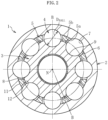
FIG. 2 is a transverse sectional view of the plunging type constant velocity universal joint according to the embodiment of the present invention, and is a transverse sectional view taken along the line A-A ofFIG. 1 . -
FIG. 3 is a transverse sectional view for illustrating angular contact between a track groove and a torque transmission ball and internal rotational backlash in the plunging type constant velocity universal joint of this embodiment. -
FIG. 4 is a longitudinal sectional view for illustrating an axial clearance between the torque transmission ball and a pocket of a cage. -
FIG. 5 is a longitudinal sectional view for illustrating the axial clearance between the torque transmission ball and the pocket of the cage and a spherical clearance between a spherical outer peripheral surface of an inner joint member and a spherical inner peripheral surface of the cage in the plunging type constant velocity universal joint of this embodiment. -
FIG. 6 is a schematic view for illustrating a state at a high normal operating angle and a state at a related-art normal operating angle for comparison. -
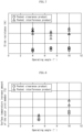
FIG. 7 is a graph for showing a test result of slide resistance in the plunging type constant velocity universal joint of this embodiment and in a related-art standard specification product. -
FIG. 8 is a graph for showing a test result of a surface temperature increase amount of an outer joint member in the plunging type constant velocity universal joint of this embodiment and in the related-art standard specification product. - A plunging type constant velocity universal joint according to an embodiment of the present invention is described with reference to
FIG. 1 to FIG. 8 .FIG. 1 is a longitudinal sectional view of a plunging type constant velocity universal joint of this embodiment, and is a longitudinal sectional view taken along the line B-N-B ofFIG. 2. FIG. 2 is a transverse sectional view of the plunging type constant velocity universal joint of this embodiment, and is a transverse sectional view taken along the line A-A ofFIG. 1 .FIG. 3 is a transverse sectional view for illustrating angular contact between a track groove and a torque transmission ball and internal rotational backlash in the plunging type constant velocity universal joint of this embodiment.FIG. 4 is a longitudinal sectional view for illustrating an axial clearance between the torque transmission ball and a pocket of a cage.FIG. 5 is a longitudinal sectional view for illustrating the axial clearance between the torque transmission ball and the pocket of the cage and a spherical clearance between a spherical outer peripheral surface of an inner joint member and a spherical inner peripheral surface of the cage in the plunging type constant velocity universal joint of this embodiment.FIG. 6 is a schematic view for illustrating a state at a high normal operating angle and a state at a related-art normal operating angle for comparison.FIG. 7 is a graph for showing a test result of slide resistance in the plunging type constant velocity universal joint of this embodiment and in a related-art standard specification product.FIG. 8 is a graph for showing a test result of a surface temperature increase amount of an outer joint member in the plunging type constant velocity universal joint of this embodiment and in the related-art standard specification product. - As illustrated in
FIG. 1 andFIG. 2 , a plunging type constant velocityuniversal joint 1 is a so-called double-offset plunging type constant velocity universal joint (sometimes abbreviated as "DOJ"), and mainly comprises an outerjoint member 2, an innerjoint member 3,torque transmission balls 4, and acage 5. A cylindrical innerperipheral surface 6 of the outerjoint member 2 has eighttrack grooves 7. Thetrack grooves 7 are formed at equal intervals in a circumferential direction and linearly extend along an axial direction. A spherical outerperipheral surface 8 of the innerjoint member 3 hastrack grooves 9 which are opposed to thetrack grooves 7 of the outerjoint member 2. Thetrack grooves 9 are formed at equal intervals in a circumferential direction and linearly extend along the axial direction. Eight torque transmission balls (hereinafter simply referred to also as "balls") 4 are individually incorporated between thetrack grooves 7 of the outerjoint member 2 and thetrack grooves 9 of the innerjoint member 3. Theballs 4 are received inpockets 5a of thecage 5. - The
cage 5 comprises a spherical outerperipheral surface 11 and a spherical innerperipheral surface 12. The spherical outerperipheral surface 11 is fitted to and guided in contact with the cylindrical innerperipheral surface 6 of the outerjoint member 2. The spherical innerperipheral surface 12 is fitted to and guided in contact with the spherical outerperipheral surface 8 of the innerjoint member 3. The spherical outerperipheral surface 11 of thecage 5 is formed to have a curvature radius Rc1 about a curvature center O1, and the spherical innerperipheral surface 12 is formed to have a curvature radius Rc2 about a curvature center O2. The spherical outerperipheral surface 8 of the innerjoint member 3 is formed to have a curvature radius Ri about the curvature center O2. The curvature centers O1 and O2 are located on an axis N, and are offset by equal distances F in the axial direction with respect to a joint center O. With this configuration, when the joint forms an operating angle, theballs 4 are always guided on a plane bisecting an angle formed by both axes of the outerjoint member 2 and the innerjoint member 3, thereby achieving transmission between two shafts with constant-velocity rotation. - A
stop ring groove 15 is provided at an opening-side end portion of the outerjoint member 2, and astop ring 17 is mounted to thestop ring groove 15, thereby preventing an inner assembly illustrated inFIG. 1 comprising the innerjoint member 3, theballs 4, and thecage 5 from moving out from the opening-side end portion of the outerjoint member 2. The opening-side end portion of the outerjoint member 2 has, on an outer periphery thereof, a boot-mountinggroove 16. A stem portion (shaft portion) 2b is integrally formed on a counter-opening side of the outerjoint member 2, and is coupled to a differential (not shown). - The spherical outer
peripheral surface 8 of the innerjoint member 3 has thelinear track grooves 9, and hence a groove depth of each of thetrack grooves 9 becomes smaller as extending from a center of the innerjoint member 3 in the axial direction toward both ends. A spline (including serration, which similarly applies to the following description) 14 is formed on a coupling hole 13 of the innerjoint member 3. A shaft end portion of an intermediate shaft (not shown) is spline-fitted to the coupling hole 13, and is fixed to the innerjoint member 3 by a shoulder portion of the intermediate shaft and the stop ring in the axial direction. - Eight
pockets 5a are formed on the axial center of thecage 5 indicated by the line A-A ofFIG. 1 at equal intervals in a circumferential direction, andpillar portions 5b (seeFIG. 2 ) are each provided betweenadjacent pockets 5a. Acutout 5c for receiving the innerjoint member 3 to be incorporated therein is formed along an inner periphery of a large-diameter-side end portion of thecage 5. Astopper surface 5d of thecage 5 has a conical shape so that thestopper surface 5d is tangentially connected to the spherical outerperipheral surface 11. In the plunging type constant velocityuniversal joint 1 of this embodiment, the maximum operating angle is set to, for example, 25°. When the joint forms an operating angle, thecage 5 is inclined at half an angle formed by both axes of the outerjoint member 2 and the innerjoint member 3. Thus, an inclination angle S of thestopper surface 5d is set to 12.5°. With this configuration, the maximum allowable angle of the plunging type constant velocityuniversal joint 1 can be restricted. - With reference to
FIG. 3 , angular contact between each of thetrack groove 7 of the outerjoint member 2 and thetrack groove 9 of the innerjoint member 3 and thetorque transmission ball 4 and internal rotational backlash are described.FIG. 3 shows onetrack groove 7, onetrack groove 9, and onetorque transmission ball 4 taken along the line B-N ofFIG. 2 . The transverse cross sections of thetrack groove 7 of the outerjoint member 2 and the transverse section of thetrack groove 9 of the innerjoint member 3 are each formed into a gothic arch shape which is formed by a combination of two arcs. Therefore, theball 4 is held in angular contact with thetrack groove 7 at twopoints C 1 and C2 and with thetrack groove 9 at two points C3 and C4. The transverse cross sectional shape of each of thetrack grooves - As illustrated in
FIG. 3 , a pitch circle diameter of thetrack groove 7 of the outerjoint member 2 is represented by ToPCD, and a pitch circle diameter of thetrack groove 9 of the innerjoint member 3 is represented by TiPCD. ToPCD is set larger than TiPCD by, for example, about 0.050 mm at a median value. As a result, a center Ob of thetorque transmission ball 4 is located at a radially intermediate position between ToPCD and TiPCD, and a track clearance is formed in a track contact angle α direction between theball 4 and each of thetrack groove 7 of the outerjoint member 2 and thetrack groove 9 of the innerjoint member 3. A track clearance δ1 in the circumferential direction is generated based on the track clearance in the track contact angle α direction. The rotational backlash amount in the joint when the innerjoint member 3 and the outerjoint member 2 are rotated relative to each other is four times larger than the track clearance δ1 in the circumferential direction. - In the plunging type constant velocity
universal joint 1 of this embodiment, the rotational backlash amount in the joint is set to 15 minutes or less. Thus, torque load responsiveness in the EV is also favorable. Further, the transverse cross sectional shape of each of thetrack grooves FIG. 3 , the dimensional difference between TiPCD and ToPCD and the track clearance are illustrated in an exaggerated manner. - The track contact angle α is an angle α between a straight line La and a straight line Lb in
FIG. 3 . The straight line La is a center line of each of the transverse cross sections of thetrack grooves FIG. 2 . The straight line Lb is a straight line connecting each of contact points C1, C2, C3, and C4 of theball 4 on side surfaces of thetrack grooves ball 4. - Next, the axial clearance between the
pocket 5a of thecage 5 and thetorque transmission ball 4 is described with reference toFIG. 4 . When the diameter of theball 4 is represented by DBALL, and the width of thepocket 5a of thecage 5 is represented by Lw, in a case of Lw<DBALL, a negative axial clearance is secured, and an interference is secured between theball 4 and thepocket 5a. In contrast, in a case of Lw>DBALL, a positive axial clearance is secured, and a clearance is secured between theball 4 and thepocket 5a. - Here, the concepts and the findings in the development process of the present invention are described. As a technology trend, in recent automobiles, engines have been reduced in vibration, and vibration of a drive source is extremely reduced in the EV. The inventors of the present invention have focused on such a latest technology trend, and have studied a spherical clearance of a DOJ having related-art standard specifications. This study served as a clue leading to the present invention.
- In the spherical clearance in the DOJ having the standard specifications, a spherical clearance that allows guide in contact between the spherical inner
peripheral surface 12 of thecage 5 and the spherical outerperipheral surface 8 of the innerjoint member 3 is about 0.050 mm at a median value. With the spherical clearance, the axial backlash amount between thecage 5 and the innerjoint member 3 is about 0.15 mm. Thus, the movable amount of the innerjoint member 3 in the axial direction with respect to the outerjoint member 2 is 0.30 mm which is twice as large as about 0.15 mm. - The following concept was obtained. As described above, with the reduction in vibration of the engine and the reduction in vibration of the drive source which are the latest technology trend, based on the spherical clearance of the DOJ having the standard specifications, when the axial clearance between the
ball 4 and thepocket 5a of thecage 5 is opened, small slide resistance of the innerjoint member 3 with respect to the outerjoint member 2 is enabled by smooth rolling of the ball within a range of 0.30 mm. Based on this, new specifications of the DOJ that satisfy slide resistance, durability at the high normal operating angle, and constant velocity characteristics were found out. In addition, recent engine vehicles have been reduced in vibration, and it was verified that the vibration can be damped sufficiently with the axial backlash amount within the above-mentioned range. - The focusing, study, concept, and verification as described above are first attempts for those skilled in the art. This is because an axial backlash amount between a cage and an inner joint member when an engine vibration is large in the related-art is secured in 1 mm or more, and it has been widely understood for many years by those skilled in the art that the vibration of the engine cannot be damped by the joint unless the axial backlash amount in such an extent is provided.
- The plunging type constant velocity
universal joint 1 of this embodiment has a characteristic configuration in which (1) based on spherical surface specifications of normal type in which the curvature radius of the spherical inner peripheral surface of the cage and the curvature radius of the spherical outer peripheral surface of the inner joint member are set to be substantially equal to each other, and the spherical clearance that allows guide in contact is formed between the spherical inner peripheral surface of the cage and the spherical outer peripheral surface of the inner joint member, (2) the plunging type constant velocity universal joint having new specifications of the DOJ in which a positive axial clearance is formed between the pocket of the cage and the torque transmission ball is provided. - The characteristic configuration of the plunging type constant velocity
universal joint 1 of this embodiment is specifically described with reference toFIG. 5 . InFIG. 5 , the main part ofFIG. 1 is enlarged, and the axial clearance between thetorque transmission ball 4 and thepocket 5a of thecage 5 and the spherical clearance between the spherical outerperipheral surface 8 of the innerjoint member 3 and the spherical innerperipheral surface 12 of thecage 5 are illustrated in an exaggerated manner. A positive axial clearance δ2 is formed between theball 4 and thepocket 5a of thecage 5. The positive axial clearance δ2 is represented with δ2=Lw-DBALL, and it is desired that δ2 be within a range of from +0.001 mm to +0.050 mm. With this configuration, theball 4 can roll smoothly in thepocket 5a, and a rolling region of theball 4 on thetrack grooves joint member 2 and the innerjoint member 3 increases, thereby reducing the slide resistance. In the plunging type constant velocityuniversal joint 1 of this embodiment, δ2 is set within a range of from +0.001 mm to +0.050 mm. - The spherical inner
peripheral surface 12 of thecage 5 is formed to have the curvature radius Rc2 about the curvature center O2, and the spherical outerperipheral surface 8 of the innerjoint member 3 is formed to have the curvature radius Ri about the curvature center O2. A spherical clearance δ3 between the spherical innerperipheral surface 12 of thecage 5 and the spherical outerperipheral surface 8 of the innerjoint member 3 is represented with δ3=2×(Rc2-Ri), and the spherical clearance δ3 is about 0.050 mm at a median value. The spherical clearance δ3 refers to a spherical clearance that allows guide in contact between the spherical outer peripheral surface of the inner joint member and the spherical inner peripheral surface of the cage in the Description and the claims. - An axial clearance δ4/2 on one side between the
cage 5 and the innerjoint member 3 due to the spherical clearance δ3 is about 0.15 mm, and a movable amount of the innerjoint member 3 with respect to the outerjoint member 2 in the axial direction is about 0.30 mm which is twice as large as about 0.15 mm. In recent engine vehicles having been reduced in vibration, the vibration can be damped sufficiently with the movable amount in the axial direction within the above-mentioned range. Thus, the axial clearance δ4 between thecage 5 and the innerjoint member 3 and the positive axial clearance δ2 between theball 4 and thepocket 5a of thecage 5 mutually work, thereby being capable of reducing the slide resistance. Further, the durability at the high normal operating angle and the constant velocity characteristics can be satisfied. -
FIG. 6 is a schematic view for illustrating a state at a high normal operating angle (for example, about 10°) in a recent SUV and a state at a related-art normal operating angle for comparison. As illustrated inFIG. 6 , in adrive shaft 20, a fixed type constant velocity universal joint 21 at an out-board end is coupled to a wheel W, and the plunging type constant velocityuniversal joint 1 at an in-board end is coupled to a differential Df. The left half inFIG. 6 shows a state at a high normal operating angle θ1, and the right half shows a state at a related-art normal operating angle θ2. In the case of the high normal operating angle θ1, the height of the differential Df from the ground is higher than that in the case of the related-art normal operating angle θ2 by Δh, thereby increasing travel performance. However, the normal operating angle increases, thereby increasing the load on the torque transmission balls. - Here, the normal operating angle in the Description is defined. The normal operating angle refers to an operating angle generated in a plunging type constant velocity universal joint for a drive shaft when a steering wheel is set to a straight advancing state in an automobile when one person rides on a horizontal and flat road surface. A related-art normal operating angle in a drive shaft for a current passenger vehicle or the like is relatively small, and is normally used at about 6°.
- The durability of the plunging type constant velocity universal joint of DOJ type decreases as a use operating angle is higher. In the plunging type constant velocity universal joint of DOJ type, when an operating angle is given, a force acting on the ball varies during one rotation, and at the maximum load, a load larger than that at the operating angle of 0° by several percent to several times depending on the angle is applied. For example, when the normal operating angle increases, and the normal operating angle is increased from the current normal operating angle of 6° to 10°, the maximum load applied to the ball increases by from about 20% to about 30%.
- In the spherical surface specifications of normal type in which the spherical clearance δ3 between the spherical inner
peripheral surface 12 of thecage 5 and the spherical outerperipheral surface 8 of the innerjoint member 3 is set to about 0.050 mm at a median value, for a product in which a positive axial clearance is secured between thepocket 5a of thecage 5 and the torque transmission ball 4 (pocket clearance product) and a product in which a negative axial clearance (pocket interference product) is secured therebetween, slide resistance and a surface temperature increase amount of the outer joint member (outer ring) was tested and evaluated. A test product is called an EDJ in NTN which uses eight balls, and has a joint size of #104. - The slide resistance of the plunging type constant velocity
universal joint 1 of DOJ type was analyzed, and it was found out that, as an effective measure for reducing the slide resistance, the positive axial clearance δ2 between thepocket 5a of thecage 5 and theball 4 contributed to the reduction in slide resistance. It was verified that when the positive axial clearance δ2 was given, the rolling region increased between theball 4 and thetrack grooves joint member 2 and the innerjoint member 3, thereby being capable of reducing the slide resistance. The test result of the slide resistance is shown inFIG. 7 . -
- ·Load torque: 98 Nm
- ·No rotation
- Axial vibration width : ±0.1 mm (frequency of 20 Hz)
- The durability of the plunging type constant velocity
universal joint 1 of DOJ type decreases as a use operating angle is higher. As the operating angle is higher, the load acting on theball 4 increases to increase the track contact pressure. With this, heat generation during rotation of the joint also increases, thereby leading to the reduction in durability. As a countermeasure thereagainst, it was verified that: it was effective for suppressing the heat generation that the positive axial clearance δ2 was given between thepocket 5a of thecage 5 and theball 4; and theball 4 rolled while suppressing sliding between theball 4 and each of thetrack grooves joint member 2 and the innerjoint member 3, thereby being capable of reducing a friction between theball 4 and each of thetrack grooves FIG. 8 . The effect is remarkable particularly at the high normal operating angle (10°). -
- ·Load torque: 373 Nm
- Number of rotations: 200 rpm
- Operating angle: 5°, 10°
- In the embodiment and the example as described above, the plunging type constant velocity
universal joint 1 of DOJ type using the eighttorque transmission balls 4 has been exemplified. However, the present invention is not limited thereto, and can be carried out as appropriate in a range of the number oftorque transmission balls 4 of from five to eight. The plunging type constant velocity universal joint suitable for power transmission systems such as automobiles and various industrial machines can be configured. Further, the number oftorque transmission balls 4 may be eight or more. - The present invention is not limited to the above-mentioned embodiment and example. As a matter of course, the present invention may be carried out in various modes without departing from the spirit of the present invention. The scope of the present invention is defined in claims, and encompasses equivalents described in claims and all changes within the scope of claims.
-
- 1
- plunging type constant velocity universal joint
- 2
- outer joint member
- 3
- inner joint member
- 4
- torque transmission ball
- 5
- cage
- 5a
- 6
- cylindrical inner peripheral surface
- 7
- track groove
- 8
- spherical outer peripheral surface
- 9
- track groove
- 11
- spherical outer peripheral surface
- 12
- spherical inner peripheral surface
- DBALL
- ball diameter
- F
- offset amount
- O
- joint center
- O1
- curvature center
- O2
- curvature center
- δ1
- track clearance in circumferential direction
- δ2
- positive axial clearance between ball and pocket
- δ3
- spherical clearance
- δ4
- axial clearance between cage and inner joint member
Claims (5)
- A plunging type constant velocity universal joint, comprising:an outer joint member comprising a cylindrical inner peripheral surface having a plurality of linear track grooves extending along an axial direction;an inner joint member comprising a spherical outer peripheral surface having a plurality of linear track grooves which are opposed to the plurality of linear track grooves of the outer joint member and extend along the axial direction;a plurality of torque transmission balls incorporated between the plurality of linear track grooves of the outer joint member and the plurality of linear track grooves of the inner joint member; anda cage, which is configured to accommodate the torque transmission balls in pockets, and comprises a spherical outer peripheral surface and a spherical inner peripheral surface, which are guided in contact with the cylindrical inner peripheral surface of the outer joint member and the spherical outer peripheral surface of the inner joint member, respectively,wherein a curvature center of the spherical outer peripheral surface and a curvature center of the spherical inner peripheral surface of the cage are offset toward opposite sides in the axial direction with respect to a joint center,wherein a spherical clearance that allows guide in contact is formed between the spherical outer peripheral surface of the inner joint member and the spherical inner peripheral surface of the cage, andwherein a positive axial clearance is formed between the pocket of the cage and the torque transmission ball.
- The plunging type constant velocity universal joint according to claim 1, wherein the positive axial clearance between the pocket of the cage and the torque transmission ball is set within a range of from +0.001 mm to +0.050 mm.
- The plunging type constant velocity universal joint according to claim 1 or 2, wherein a rotational backlash amount in the plunging type constant velocity universal joint is set to 15 minutes or less.
- The plunging type constant velocity universal joint according to any one of claims 1 to 3, wherein a transverse cross sectional shape of each of the track groove of the outer joint member and the track groove of the inner joint member is a gothic arch shape that allows angular contact with the torque transmission ball.
- The plunging type constant velocity universal joint according to any one of claims 1 to 4, wherein the number of the plurality of torque transmission balls is set within a range of from five to eight.
Applications Claiming Priority (2)
| Application Number | Priority Date | Filing Date | Title |
|---|---|---|---|
| JP2021138190A JP2023032205A (en) | 2021-08-26 | 2021-08-26 | Sliding constant velocity universal joint |
| PCT/JP2022/030153 WO2023026831A1 (en) | 2021-08-26 | 2022-08-05 | Sliding-type constant-velocity joint |
Publications (2)
| Publication Number | Publication Date |
|---|---|
| EP4394200A1 true EP4394200A1 (en) | 2024-07-03 |
| EP4394200A4 EP4394200A4 (en) | 2024-12-18 |
Family
ID=84774114
Family Applications (1)
| Application Number | Title | Priority Date | Filing Date |
|---|---|---|---|
| EP22861121.6A Withdrawn EP4394200A4 (en) | 2021-08-26 | 2022-08-05 | Plunging type constant velocity universal joint |
Country Status (5)
| Country | Link |
|---|---|
| US (1) | US20240426348A1 (en) |
| EP (1) | EP4394200A4 (en) |
| JP (1) | JP2023032205A (en) |
| CN (2) | CN115727067A (en) |
| WO (1) | WO2023026831A1 (en) |
Families Citing this family (1)
| Publication number | Priority date | Publication date | Assignee | Title |
|---|---|---|---|---|
| KR102783816B1 (en) * | 2024-09-26 | 2025-03-21 | 서한이노빌리티(주) | A Constant Velocity Joint |
Family Cites Families (7)
| Publication number | Priority date | Publication date | Assignee | Title |
|---|---|---|---|---|
| JP3859295B2 (en) | 1996-06-28 | 2006-12-20 | Ntn株式会社 | Sliding type constant velocity universal joint |
| JP2002054650A (en) | 2000-08-09 | 2002-02-20 | Ntn Corp | Sliding-type constant velocity universal joint and drive shaft using the same |
| JP5073190B2 (en) | 2005-09-22 | 2012-11-14 | Ntn株式会社 | Sliding constant velocity universal joint |
| JP2007224995A (en) * | 2006-02-22 | 2007-09-06 | Ntn Corp | Constant velocity joint |
| JP2010159775A (en) * | 2009-01-06 | 2010-07-22 | Ntn Corp | Sliding type constant velocity universal joint |
| JP7292008B2 (en) * | 2017-03-17 | 2023-06-16 | Ntn株式会社 | Sliding constant velocity universal joint for rear wheel drive shaft |
| JP7437868B2 (en) * | 2018-04-24 | 2024-02-26 | Ntn株式会社 | Sliding type constant velocity universal joint for propeller shaft |
-
2021
- 2021-08-26 JP JP2021138190A patent/JP2023032205A/en active Pending
-
2022
- 2022-08-05 US US18/684,345 patent/US20240426348A1/en active Pending
- 2022-08-05 WO PCT/JP2022/030153 patent/WO2023026831A1/en not_active Ceased
- 2022-08-05 EP EP22861121.6A patent/EP4394200A4/en not_active Withdrawn
- 2022-08-12 CN CN202210971321.0A patent/CN115727067A/en active Pending
- 2022-08-12 CN CN202222129435.9U patent/CN218266870U/en active Active
Also Published As
| Publication number | Publication date |
|---|---|
| WO2023026831A8 (en) | 2023-10-26 |
| CN115727067A (en) | 2023-03-03 |
| CN218266870U (en) | 2023-01-10 |
| WO2023026831A1 (en) | 2023-03-02 |
| EP4394200A4 (en) | 2024-12-18 |
| US20240426348A1 (en) | 2024-12-26 |
| JP2023032205A (en) | 2023-03-09 |
Similar Documents
| Publication | Publication Date | Title |
|---|---|---|
| KR100556574B1 (en) | Sliding Constant Velocity Universal Joint | |
| US8771092B2 (en) | Fixed type constant velocity universal joint | |
| US9206855B2 (en) | Fixed type constant-velocity universal joint | |
| US20160138660A1 (en) | Fixed-type constant velocity universal joint | |
| EP2905491B1 (en) | Fixed type constant-velocity universal joint | |
| EP2908020B1 (en) | Fixed-type constant-velocity universal joint | |
| CN102066794A (en) | Fixed uniform-motion universal joint | |
| US11371564B2 (en) | Plunging type constant velocity universal joint | |
| US6910970B2 (en) | Constant velocity universal joint | |
| EP2924306B1 (en) | Fixed type constant velocity universal joint | |
| EP2778452A1 (en) | Fixed constant-velocity universal joint | |
| US20240426348A1 (en) | Plunging type constant velocity universal joint | |
| CN101326380B (en) | Constant velocity spherical universal joints in the form of opposing raceway joints | |
| US8323116B2 (en) | Universal joint | |
| WO2005064175A1 (en) | Constant velocity universal joint | |
| US12429095B2 (en) | Plunging-type constant velocity universal joint | |
| JP7837162B2 (en) | Sliding constant velocity universal joint | |
| JP2024090755A (en) | Sliding constant velocity joint | |
| JP2024083925A (en) | Fixed constant velocity joint | |
| US20240426349A1 (en) | Plunging type constant velocity universal joint | |
| US20130316838A1 (en) | Counter track joint with axial displacement range | |
| EP3015729B1 (en) | Fixed-type constant velocity universal joint | |
| KR20250005476A (en) | tripod joint | |
| JP2026046344A (en) | Sliding constant velocity universal joint | |
| JP2023161283A (en) | Sliding type constant velocity universal joint |
Legal Events
| Date | Code | Title | Description |
|---|---|---|---|
| STAA | Information on the status of an ep patent application or granted ep patent |
Free format text: STATUS: THE INTERNATIONAL PUBLICATION HAS BEEN MADE |
|
| PUAI | Public reference made under article 153(3) epc to a published international application that has entered the european phase |
Free format text: ORIGINAL CODE: 0009012 |
|
| STAA | Information on the status of an ep patent application or granted ep patent |
Free format text: STATUS: REQUEST FOR EXAMINATION WAS MADE |
|
| 17P | Request for examination filed |
Effective date: 20240319 |
|
| AK | Designated contracting states |
Kind code of ref document: A1 Designated state(s): AL AT BE BG CH CY CZ DE DK EE ES FI FR GB GR HR HU IE IS IT LI LT LU LV MC MK MT NL NO PL PT RO RS SE SI SK SM TR |
|
| REG | Reference to a national code |
Ref country code: DE Ref legal event code: R079 Free format text: PREVIOUS MAIN CLASS: F16D0003227000 Ipc: F16D0003223000 |
|
| DAV | Request for validation of the european patent (deleted) | ||
| DAX | Request for extension of the european patent (deleted) | ||
| A4 | Supplementary search report drawn up and despatched |
Effective date: 20241119 |
|
| RIC1 | Information provided on ipc code assigned before grant |
Ipc: F16D 3/223 20110101AFI20241113BHEP |
|
| STAA | Information on the status of an ep patent application or granted ep patent |
Free format text: STATUS: THE APPLICATION IS DEEMED TO BE WITHDRAWN |
|
| 18D | Application deemed to be withdrawn |
Effective date: 20250607 |