EP4394189A1 - Threaded fastening arrangement - Google Patents
Threaded fastening arrangement Download PDFInfo
- Publication number
- EP4394189A1 EP4394189A1 EP23220508.8A EP23220508A EP4394189A1 EP 4394189 A1 EP4394189 A1 EP 4394189A1 EP 23220508 A EP23220508 A EP 23220508A EP 4394189 A1 EP4394189 A1 EP 4394189A1
- Authority
- EP
- European Patent Office
- Prior art keywords
- slotted hole
- fastening part
- fastening
- component
- abutment surface
- Prior art date
- Legal status (The legal status is an assumption and is not a legal conclusion. Google has not performed a legal analysis and makes no representation as to the accuracy of the status listed.)
- Granted
Links
Images


Classifications
-
- F—MECHANICAL ENGINEERING; LIGHTING; HEATING; WEAPONS; BLASTING
- F16—ENGINEERING ELEMENTS AND UNITS; GENERAL MEASURES FOR PRODUCING AND MAINTAINING EFFECTIVE FUNCTIONING OF MACHINES OR INSTALLATIONS; THERMAL INSULATION IN GENERAL
- F16B—DEVICES FOR FASTENING OR SECURING CONSTRUCTIONAL ELEMENTS OR MACHINE PARTS TOGETHER, e.g. NAILS, BOLTS, CIRCLIPS, CLAMPS, CLIPS OR WEDGES; JOINTS OR JOINTING
- F16B33/00—Features common to bolt and nut
- F16B33/002—Means for preventing rotation of screw-threaded elements
-
- F—MECHANICAL ENGINEERING; LIGHTING; HEATING; WEAPONS; BLASTING
- F16—ENGINEERING ELEMENTS AND UNITS; GENERAL MEASURES FOR PRODUCING AND MAINTAINING EFFECTIVE FUNCTIONING OF MACHINES OR INSTALLATIONS; THERMAL INSULATION IN GENERAL
- F16B—DEVICES FOR FASTENING OR SECURING CONSTRUCTIONAL ELEMENTS OR MACHINE PARTS TOGETHER, e.g. NAILS, BOLTS, CIRCLIPS, CLAMPS, CLIPS OR WEDGES; JOINTS OR JOINTING
- F16B35/00—Screw-bolts; Stay-bolts; Screw-threaded studs; Screws; Set screws
- F16B35/04—Screw-bolts; Stay-bolts; Screw-threaded studs; Screws; Set screws with specially-shaped head or shaft in order to fix the bolt on or in an object
- F16B35/041—Specially-shaped shafts
- F16B35/048—Specially-shaped necks
-
- F—MECHANICAL ENGINEERING; LIGHTING; HEATING; WEAPONS; BLASTING
- F16—ENGINEERING ELEMENTS AND UNITS; GENERAL MEASURES FOR PRODUCING AND MAINTAINING EFFECTIVE FUNCTIONING OF MACHINES OR INSTALLATIONS; THERMAL INSULATION IN GENERAL
- F16B—DEVICES FOR FASTENING OR SECURING CONSTRUCTIONAL ELEMENTS OR MACHINE PARTS TOGETHER, e.g. NAILS, BOLTS, CIRCLIPS, CLAMPS, CLIPS OR WEDGES; JOINTS OR JOINTING
- F16B5/00—Joining sheets or plates, e.g. panels, to one another or to strips or bars parallel to them
- F16B5/02—Joining sheets or plates, e.g. panels, to one another or to strips or bars parallel to them by means of fastening members using screw-thread
- F16B5/0216—Joining sheets or plates, e.g. panels, to one another or to strips or bars parallel to them by means of fastening members using screw-thread the position of the plates to be connected being adjustable
- F16B5/0225—Joining sheets or plates, e.g. panels, to one another or to strips or bars parallel to them by means of fastening members using screw-thread the position of the plates to be connected being adjustable allowing for adjustment parallel to the plane of the plates
Definitions
- Components can be mounted to each other using threaded means such as bolts and nuts.
- a fastening part has a flanged contact surface in contact with the component, that has a hole for accommodating the bolt.
- the pair of threaded fastening parts are rotated relative to each other, to provide for a clamping arrangement through the threads.
- a disadvantage of using glue or a friction conditioner is that it may make forming the releasable connection more difficult to which end a slotted hole may provide the proper counter torque during the assembly.
- a slotted hole in the component may accommodate an abutment surface that extends from the flanged contact surface and that prevents rotation of the first fastening part.
- the slotted hole requires a relative orientation of the abutment surface of the fastening part to accommodate the fastening part correctly.
- the invention aims to counteract the above disadvantages, by providing for a threaded fastening arrangement, preferably with a high friction thread that easily can be releasably connected.
- the invention relates to a threaded fastening arrangement for mounting a component to a base component, comprising a pair of cooperating fastening parts and a component.
- the component comprises a slotted hole defined by a slotted hole surface and wherein a first fastening part of the pair of cooperating fastening parts comprises an abutment surface arranged to substantially limit rotation of the first fastening part relative to the component when the abutment surface abuts the slotted hole surface.
- a guiding surface is provided.
- the guiding surface is arranged to provide for a rotational movement of the first fastening part when the first fastening part is provided in the slotted hole.
- a person assembling the component to a base component can provide the first fastening part in the slotted hole of the component.
- the above described guiding surface allows for relatively easy placement of the first fastening part in the elongated slot as a person assembling the component to the base component using the described threaded fastening arrangement can place the first fastening part in a comparable way to a common first fastening part such as a bolt.
- the person assembly now only needs to apply an axial downward force, for example using commonly available plate to place the first fastening part in the elongated surface.
- the method has the benefit that no individual rotational positioning of the fastening parts is necessary since they are so called 'self positioning' and only need axial displacement that can easily be provided by a pressing tool that may provide axial pressing force on the fastening parts without needing to individually align and position the fastening parts.
Landscapes
- Engineering & Computer Science (AREA)
- General Engineering & Computer Science (AREA)
- Mechanical Engineering (AREA)
- Connection Of Plates (AREA)
- Bolts, Nuts, And Washers (AREA)
Abstract
Description
- The invention relates to a threaded fastening arrangement for mounting a component to a base component comprising a pair of cooperating fastening parts and a component.
- Components can be mounted to each other using threaded means such as bolts and nuts. In a conventional context, a fastening part has a flanged contact surface in contact with the component, that has a hole for accommodating the bolt. Also conventionally, the pair of threaded fastening parts are rotated relative to each other, to provide for a clamping arrangement through the threads.
- In certain applications, it is preferred that the releasable connection cannot be released by accident. For example, when components are connected via a bolt and nut heavy vibration may release the connection. In order to mitigate this effect, a glue or friction conditioner may be applied to the bolt and / or nut. The glue or friction conditioner may increase the friction applied by the nut on the bolt and vice versa, thereby making it unlikely that the bolt and nut are released. In case the bolt and nut need to be released on purpose, e.g. maintenance or replacement of components, the glue or friction conditioner may be removed by applying heat or a solvent. Afterwards, a new friction conditioner or glue may be applied again when the bolt and nut are used to form a releasable connection once more.
- A disadvantage of using glue or a friction conditioner is that it may make forming the releasable connection more difficult to which end a slotted hole may provide the proper counter torque during the assembly. In such context, it is undesired that one of the fastening part rotates during assembly, and a slotted hole in the component may accommodate an abutment surface that extends from the flanged contact surface and that prevents rotation of the first fastening part. However the slotted hole requires a relative orientation of the abutment surface of the fastening part to accommodate the fastening part correctly. In practice, there may be situations that it is not easy to accommodate the fastening part, in particular, if more than one fastening parts are used and manual positioning of the fastening part is problematic or even impossible.
- The invention aims to counteract the above disadvantages, by providing for a threaded fastening arrangement, preferably with a high friction thread that easily can be releasably connected.
- To this end, the invention relates to a threaded fastening arrangement for mounting a component to a base component, comprising a pair of cooperating fastening parts and a component. The component comprises a slotted hole defined by a slotted hole surface and wherein a first fastening part of the pair of cooperating fastening parts comprises an abutment surface arranged to substantially limit rotation of the first fastening part relative to the component when the abutment surface abuts the slotted hole surface. The slotted hole or the first fastening part comprises a guiding surface contiguous to the abutment surface and shaped to rotate the first fastening part relative to the slotted hole such that the abutment surface abuts the slotted hole surface thereby causing the first fastening part to become rotationally locked with the component. The threaded fastening arrangement has the advantage that the fastening parts need not be separately rotated to bring the fastening part in position in the slotted hole, which offers efficiency and safety benefits when assembling the fastening parts for mounting a component to a base component
- A threaded fastening arrangement can provide for a releasable connection between components. Having a releasable connection allows for the connection to be undone without damaging the components, for example when maintenance needs to be performed or components need to be repaired. In the invention, at least one of the components that needs to be mounted to a base component, or second component, has a slotted hole, i.e. an elongated opening. The slotted hole is preferably a straight slotted hole, i.e. its longitudinal direction is substantially not curved. A first part of the fastening part of the pair of cooperating fastening parts comprises an abutment surface that can abut with a slotted hole surface. For example, the abutment surface may be a substantially planar surface provided on the first fastening means. Such a planar, or flat, surface may interface substantially with most, or all, of its surface with the surface of the slotted hole. The first fastening part is dimensioned such that, once provided in the slotted hole and the abutment surface abuts the surface of the slotted hole, slack between the first fastening part and the slotted hole surface is relatively small. In other words, the first fastening part is dimensioned such that if the abutment surface does not abut the surface of the slotted hole, the first fastening part cannot be provided in the slotted hole.
- In order to help facilitate the correct orientation of the first fastening part relative to the slotted hole, i.e. such that the abutting surface can abut the surface of the slotted hole, a guiding surface is provided. Preferably, the guiding surface is arranged to provide for a rotational movement of the first fastening part when the first fastening part is provided in the slotted hole. For example, a person assembling the component to a base component can provide the first fastening part in the slotted hole of the component. When the first fastening part is not correctly orientated, and the abutment surface does not abut the surface of the slotted hole, an axial force can be provided on the first fastening part in the direction of the component. The guiding surface will come in to contact with the component, and due to the force applied on the first fastening part, will cause the first fastening part to rotate around an axis. When the guiding surface is obliquely orientated relative to the rotation axis of the first fastening part, rotation of the first fastening part allows for the first fastening part to move further in to the slotted hole. Once the first fastening means is correctly orientated relative to the slotted hole, i.e. the abutting surface is aligned with the surface of the slotted hole, the first fastening part can move to its final position in the slotted hole, wherein the abutting surface abuts the surface of the slotted hole.
- Once the first fastening part is provided in the slotted hole such that the abutting surface abuts the surface of the slotted hole, the abutting of the surfaces causes the first fastening part to be rotationally locked with the component. In other words, the first fastening part can no longer rotate relative to the component. As a result, it is now possible to rotate the second fastening part relative to the first fastening part, for example by using an impact wrench, without the first fastening part rotation locking with the second fastening part such that both fastening parts rotate relative to the component and thus not forming a releasable connection between the component and the base component. In a further advantage, by providing an abutment surface that abuts the elongated slot and thereby forms a rotational lock between the first fastening part and the component, no additional resources need to be spent to facilitate new mounting processes or tools.
- Furthermore, the above described guiding surface allows for relatively easy placement of the first fastening part in the elongated slot as a person assembling the component to the base component using the described threaded fastening arrangement can place the first fastening part in a comparable way to a common first fastening part such as a bolt. The person assembly now only needs to apply an axial downward force, for example using commonly available plate to place the first fastening part in the elongated surface.
- In a preferred embodiment, the pair of cooperating fastening parts are a bolt and a nut. More preferably, the first fastening part can be the bolt, wherein the bolt can comprise a shaft on which the abutment surface is provided. More specifically, the abutment surface can be provided on the shaft next to a bolt head of the bold. The guiding surface can then be provided on the opposite side of the abutment surface than the bolt head. An advantage of using a bolt and a nut is that they are commonly used and relatively cheap and reliably means for releasably connecting a component to a base component. The shaft of the bolt can comprise a thread comprising a coating, preferably glue or a friction conditioner, such that a relatively high friction between the bolt thread and the corresponding nut thread can be achieved. High friction bolt / nut thread connections can be used for bolt / nut connections that may endure significant vibrations. Non-high friction bolt / nut thread connections may unintentionally release.
- The bolt can comprise at least two of abutment surfaces, preferably six abutment surfaces, provided evenly distributed around the shaft. A plurality of abutment surfaces may facilitate for even easier orientating of the bolt in the elongated slot. In a special embodiment, the plurality of provided abutment surfaces is an even number, forming pairs, wherein the pairs of abutment surfaces are provided substantially parallel to each other and on opposite sides of the shaft. This embodiment would, when the bolt is present in the elongated slot, allow for two abutment surfaces to abut to the surface of the elongated slot at the same time. This may provide for a stronger rotational lock between the bolt and the component.
- Alternatively, the nut can comprise a tapered section on which the abutment surface is provided. In such an embodiment, the nut instead of the bolt would form a rotational lock with the component. As a result the bolt needs to be driven to form the releasable connection. This embodiment may be advantageous in case there is not sufficient space for providing a bolt in the slotted hole, but there is sufficient space for providing a nut in the slotted hole.
- In addition, the invention further provides for a method of mounting a component to a base component by one or more pairs of fastening parts, wherein a first fastening part of the one or more pairs of cooperating fastening parts comprises an abutment surface arranged to substantially limit rotation of the first fastening part relative to the component when the abutment surface abuts the slotted hole surface, the method comprising: exerting an axial force only to the first fastening part of the pairs of fastening parts, and rotating the first fastening part relative to the slotted hole such that the abutment surface abuts the slotted hole surface thereby causing the first fastening part to become rotationally locked with the component.
- The method has the benefit that no individual rotational positioning of the fastening parts is necessary since they are so called 'self positioning' and only need axial displacement that can easily be provided by a pressing tool that may provide axial pressing force on the fastening parts without needing to individually align and position the fastening parts.
- Further advantageous aspects of the invention are set out in the description and appended claims.
- The technical features described in the paragraphs and sentences above can be isolated from the context, and the isolated technical features from the different paragraphs and sentences can be combined. Such combinations are herewith specifically disclosed in this description.
- The invention will further be elucidated on the basis of exemplary embodiments which are represented in the drawings. The exemplary embodiments are given by way of non-limitative illustration of the invention.
- In the drawings:
-
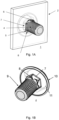
Fig. 1A and 1B shows an isometric view of a first fastening part present in a component according to the invention; -
Fig. 2 shows a side view of a first fastening mean according to an embodiment of the invention; -
Fig. 3A shows a bottom view of the first fastening mean ofFig. 2 ; -
Fig. 3B shows a front view of the component ofFig. 1 ; -
Fig 4 shows an alternative embodiment wherein the fastening part is a nut. - It is noted that the figures are only schematic representations that are given by way of non-limited examples. In the figures, the same or corresponding parts are designated with the same reference numerals.
- Turning to
Fig. 1A , a threadedfastening arrangement 1 for mounting acomponent 2 to a base component (not shown) is depicted. Thefastening arrangement 1 comprises a pair of cooperating fastening parts, of which only a first fastening part, in the form ofbolt 4 is shown for clarity, and acomponent 2. The second part is a threaded nut (not shown) that cooperates with the threaded shaft of thebolt 4. Thecomponent 2 comprises a slottedhole 5 defined by a slottedhole surface 6. The first fastening part, in the shown example abolt 4, comprises anabutment surface 7 arranged to substantially limit rotation of thefirst fastening part 4, e.g. the bolt, relative to thecomponent 2 when theabutment surface 7 abuts the slottedhole surface 6. The slottedhole surface 6 or thefirst fastening part 4 comprises a guidingsurface 8 shaped to center thefirst fastening part 4 in the slottedhole 5 such that theabutment surface 7 abuts the slottedhole surface 6, thereby causing thefirst fastening part 4 to become rotationally locked with thecomponent 2. -
Figure 1B shows the fastening part in more detail, notably a threadedshaft 9,abutment surface 7 andcontact surface 11 of aflange 10 of thebolt 4. Thebolt 4 further has guidingsurface 8 contiguous to theabutment surface 7 and shaped to rotate thefirst fastening part 4 relative to the slottedhole 5 such that theabutment surface 7 abuts the slottedhole surface 6 thereby causing thefirst fastening part 4 to become rotationally locked with thecomponent 2. - Turning to
Fig. 2 , thebolt 4, which acts as the first fastening part in the shown example, comprises ashaft 9 on which theabutment surface 7 is provided. In the shown embodiment, the bolt 3 comprises a plurality ofabutment surfaces 7, more specific sixabutment surfaces 7, provided evenly disturbed around theshaft 9. On the shaft 9 a thread is provided, which comprises a coating. More specifically, the coating is a friction conditioner or a glue. In the shown example, the guidingsurface 8 has an edge orslope 8a that, when inserted in the slottedhole 5 is angled with an angle α respective to a normal plane s representing the slotted hole edge s, which is also the contact surface of thecomponent 2, so that through axial displacement of thefirst fastening part 4 thefirst fastening part 4 is rotated relative to the slotted hole surface abutment surface until the abutment surface is parallel to the slotted hole surface.Slope 8a prevents the corners of the polygon P to get stuck on the edge of the slottedhole 5 in the plate and forces thebolt 4 into the slottedhole 5. The slope angle α may be such that the spinning direction of the nut through thread angle β will enforce an axial or "downhill" movement of the bolt into the slottedhole 5. Theedge 8a runs to this end at least in part in tangential direction under an angle α relative to normal plane s and extends radially outwards of the abutment surface to the beginning ofthread 10 to optimize a torque transfer between the edge and the slotted hole, in order to rotate the fastening part when pressed in axial direction. The angle α of the slope should be such that tan(α) is afactor 2 higher than the coefficient of friction between the edge of the slotted hole and the edge that forms the slope. This optimizes an optimal torque that results in rotation of thebolt 4, even with a substantial friction. Theedge 8a may be curved to initiate the rotation of the bolt more easily. - It is shown that the slope of guiding
surface 8 starts at the corner I of a polygon forming the abutment surfaces 7 and runs towards the start of the round part of the shaft of the bolt, point II in the figure. - In
Figure 3A the polygon dimension is shown where preferably opposite points of the polygon P are wider than the width of the straight part of the slotted hole and opposite ends of the slope (at the shaft), are less wide than the straight part of the slotted hole. The polygon P, when oriented right the polygon should fit in the slotted hole, but cannot fully rotate in the slotted shole shown inFigure 3B . In other words : in Wy < Wsy < Wx < Wsx.Figure 3B shows a preferred relative dimensioning of the slottedhole 5 relative to thefastening bolt 4. -
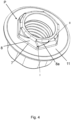
Fig 4 shows an alternative embodiment wherein the fastening part is a nut 3 with acontact surface 11, a guidingsurface 8, anabutment surface 7 and a guidingedge 8a that preferably spirals between a corner (I) ofabutment surface 7, in particular a corner of polygon P to an axial centerline (II) of theabutment surface 7. In theexample guiding surface 8 comprises a tapered section with a radius slightly smaller than the smallest diameter of the slotted hole. - Variations are understood to be comprised within the scope of the invention as defined in the appended claims.
Claims (11)
- Threaded fastening arrangement for mounting a component to a base component,- comprising a pair of cooperating fastening parts and a component;- wherein the component comprises a slotted hole defined by a slotted hole surface;- wherein a first fastening part of the pair of cooperating fastening parts comprises an abutment surface arranged to substantially limit rotation of the first fastening part relative to the component when the abutment surface abuts the slotted hole surface; and- wherein the slotted hole or the first fastening part comprises a guiding surface contiguous to the abutment surface and shaped to rotate the first fastening part relative to the slotted hole such that the abutment surface abuts the slotted hole surface thereby causing the first fastening part to become rotationally locked with the component.
- Threaded fastening arrangement according to claim 1, wherein the fastening part comprises a plurality of abutment surfaces, preferably formed as a polygon.
- Threaded fastening arrangement according to claim any preceding claim, wherein the first fastening part is a nut, wherein the nut comprises a tapered section on which the abutment surface is provided.
- Threaded fastening arrangement according to any preceding claim, wherein the first fastening part is a bolt, wherein the bolt comprises a shaft on which the abutment surface is provided.
- Threaded fastening arrangement according to claims 4, wherein the shaft further comprises a thread comprising a coating, preferably glue or a friction conditioner.
- Threaded fastening arrangement according to any of the preceding claims, wherein the guiding surface has an edge that, when inserted in the slotted hole is angled respective to the slotted hole surface, so that through axial displacement of the first fastening part the first fastening part is rotated relative to the slotted hole surface abutment surface until the abutment surface is parallel to the slotted hole surface.
- Threaded fastening arrangement according to claim 6, wherein the edge is angled in tangential direction relative to a normal plane.
- Threaded fastening arrangement according to any of the preceding claims 6 or 7, wherein the edge extends radially outwards of the abutment surface.
- Threaded fastening arrangement according to any of claims 6-8, wherein the edge has a slope angle that is directed in opposite direction of the thread angle, so that a reaction torque of a rotating second fastening part results in a rotation of the edge.
- Threaded fastening arrangement according to any preceding claim, wherein the first fastening part comprises a tapered section on which the abutment surface is provided.
- A method of mounting a component to a base component by one or more pairs of fastening parts, wherein a first fastening part of the one or more pairs of cooperating fastening parts comprises an abutment surface arranged to substantially limit rotation of the first fastening part relative to the component when the abutment surface abuts the slotted hole surface, the method comprising: exerting an axial force only to the first fastening part, and rotating the first fastening part relative to the slotted hole such that the abutment surface abuts the slotted hole surface thereby causing the first fastening part to become rotationally locked with the component.
Applications Claiming Priority (1)
| Application Number | Priority Date | Filing Date | Title |
|---|---|---|---|
| NL2033871A NL2033871B1 (en) | 2022-12-29 | 2022-12-29 | Threaded fastening arrangement |
Publications (3)
| Publication Number | Publication Date |
|---|---|
| EP4394189A1 true EP4394189A1 (en) | 2024-07-03 |
| EP4394189C0 EP4394189C0 (en) | 2025-08-20 |
| EP4394189B1 EP4394189B1 (en) | 2025-08-20 |
Family
ID=85569746
Family Applications (1)
| Application Number | Title | Priority Date | Filing Date |
|---|---|---|---|
| EP23220508.8A Active EP4394189B1 (en) | 2022-12-29 | 2023-12-28 | Threaded fastening arrangement |
Country Status (2)
| Country | Link |
|---|---|
| EP (1) | EP4394189B1 (en) |
| NL (1) | NL2033871B1 (en) |
Citations (7)
| Publication number | Priority date | Publication date | Assignee | Title |
|---|---|---|---|---|
| US2163446A (en) * | 1937-08-17 | 1939-06-20 | Richard P Heckman | Insert anchor |
| US6196356B1 (en) * | 1999-08-24 | 2001-03-06 | Terryle L. Sneed | Method and apparatus for installing elevator car and counterweight guide rails |
| EP1195534A2 (en) * | 2000-10-04 | 2002-04-10 | Kamax-Werke Rudolf Kellermann GmbH & Co. KG | Releasable fastening means with a screw element and a locking washer |
| WO2005052386A2 (en) * | 2003-11-19 | 2005-06-09 | Alpha Stamping Company | Fastener assembly |
| US20180023608A1 (en) * | 2016-07-25 | 2018-01-25 | Toyota Boshoku Kabushiki Kaisha | Fastener for fastening a resin component |
| WO2018098024A1 (en) * | 2016-11-22 | 2018-05-31 | Southco, Inc. | Quick access blind fastener |
| EP3787137A1 (en) * | 2019-08-29 | 2021-03-03 | Zurecon AG | Connecting device, connection fitting and cable tray |
-
2022
- 2022-12-29 NL NL2033871A patent/NL2033871B1/en active
-
2023
- 2023-12-28 EP EP23220508.8A patent/EP4394189B1/en active Active
Patent Citations (7)
| Publication number | Priority date | Publication date | Assignee | Title |
|---|---|---|---|---|
| US2163446A (en) * | 1937-08-17 | 1939-06-20 | Richard P Heckman | Insert anchor |
| US6196356B1 (en) * | 1999-08-24 | 2001-03-06 | Terryle L. Sneed | Method and apparatus for installing elevator car and counterweight guide rails |
| EP1195534A2 (en) * | 2000-10-04 | 2002-04-10 | Kamax-Werke Rudolf Kellermann GmbH & Co. KG | Releasable fastening means with a screw element and a locking washer |
| WO2005052386A2 (en) * | 2003-11-19 | 2005-06-09 | Alpha Stamping Company | Fastener assembly |
| US20180023608A1 (en) * | 2016-07-25 | 2018-01-25 | Toyota Boshoku Kabushiki Kaisha | Fastener for fastening a resin component |
| WO2018098024A1 (en) * | 2016-11-22 | 2018-05-31 | Southco, Inc. | Quick access blind fastener |
| EP3787137A1 (en) * | 2019-08-29 | 2021-03-03 | Zurecon AG | Connecting device, connection fitting and cable tray |
Also Published As
| Publication number | Publication date |
|---|---|
| EP4394189C0 (en) | 2025-08-20 |
| NL2033871B1 (en) | 2024-07-12 |
| EP4394189B1 (en) | 2025-08-20 |
Similar Documents
| Publication | Publication Date | Title |
|---|---|---|
| CN100404890C (en) | Washer and threaded fastening assembly including the washer | |
| US6290442B1 (en) | Locking fastener assembly for threaded joint | |
| JP6530320B2 (en) | Lock washer assembly and mounting assembly | |
| KR102948848B1 (en) | Multi-head bolt and fastening device system | |
| JP2006502360A (en) | Tolerance correction mounting device | |
| US6779957B2 (en) | Bolt, method of fastening members with the use of the bolt, and method of releasing fastening | |
| US11498193B2 (en) | Wheel hub bearing extraction tool | |
| KR20060025573A (en) | connector | |
| US12540638B2 (en) | Blind type removable fixing device, assembly comprising at least one such fixing device and method of dismantling such a fixing device | |
| JP2002130240A (en) | Releasable coupling element for a structural part, having a bolt part and a safety ring | |
| TWI547649B (en) | Fastening device | |
| CN114838048A (en) | Combined nut with anti-loosening function | |
| WO1982000965A1 (en) | Free spinning laminated nut with automatic lock | |
| US5178500A (en) | Fastener with locking retainer ring | |
| US7246542B2 (en) | Holding socket for a washer nut | |
| EP4394189B1 (en) | Threaded fastening arrangement | |
| US7309187B2 (en) | Releasable keyless bushing assembly | |
| US20250003445A1 (en) | Pawl nut with securing element | |
| JP4528544B2 (en) | Loss prevention device for wheel brake disc | |
| EP1087152B1 (en) | Shaft depressor for a slap yoke in a steering assembly | |
| CN220435221U (en) | Duplex non-loosening nut and fastening suite | |
| EP0251545A1 (en) | Brake assemblies | |
| JP2024522393A (en) | Composite wheel mounting device | |
| US12196251B2 (en) | Bearing assembly | |
| CN220469641U (en) | Hinge for airplane |
Legal Events
| Date | Code | Title | Description |
|---|---|---|---|
| PUAI | Public reference made under article 153(3) epc to a published international application that has entered the european phase |
Free format text: ORIGINAL CODE: 0009012 |
|
| STAA | Information on the status of an ep patent application or granted ep patent |
Free format text: STATUS: THE APPLICATION HAS BEEN PUBLISHED |
|
| AK | Designated contracting states |
Kind code of ref document: A1 Designated state(s): AL AT BE BG CH CY CZ DE DK EE ES FI FR GB GR HR HU IE IS IT LI LT LU LV MC ME MK MT NL NO PL PT RO RS SE SI SK SM TR |
|
| STAA | Information on the status of an ep patent application or granted ep patent |
Free format text: STATUS: REQUEST FOR EXAMINATION WAS MADE |
|
| 17P | Request for examination filed |
Effective date: 20241227 |
|
| GRAP | Despatch of communication of intention to grant a patent |
Free format text: ORIGINAL CODE: EPIDOSNIGR1 |
|
| STAA | Information on the status of an ep patent application or granted ep patent |
Free format text: STATUS: GRANT OF PATENT IS INTENDED |
|
| RIC1 | Information provided on ipc code assigned before grant |
Ipc: F16B 35/04 20060101ALI20250319BHEP Ipc: F16B 5/02 20060101AFI20250319BHEP |
|
| INTG | Intention to grant announced |
Effective date: 20250408 |
|
| GRAS | Grant fee paid |
Free format text: ORIGINAL CODE: EPIDOSNIGR3 |
|
| GRAA | (expected) grant |
Free format text: ORIGINAL CODE: 0009210 |
|
| STAA | Information on the status of an ep patent application or granted ep patent |
Free format text: STATUS: THE PATENT HAS BEEN GRANTED |
|
| AK | Designated contracting states |
Kind code of ref document: B1 Designated state(s): AL AT BE BG CH CY CZ DE DK EE ES FI FR GB GR HR HU IE IS IT LI LT LU LV MC ME MK MT NL NO PL PT RO RS SE SI SK SM TR |
|
| REG | Reference to a national code |
Ref country code: GB Ref legal event code: FG4D |
|
| REG | Reference to a national code |
Ref country code: CH Ref legal event code: EP |
|
| REG | Reference to a national code |
Ref country code: DE Ref legal event code: R096 Ref document number: 602023005901 Country of ref document: DE |
|
| REG | Reference to a national code |
Ref country code: IE Ref legal event code: FG4D |
|
| U01 | Request for unitary effect filed |
Effective date: 20250912 |
|
| U07 | Unitary effect registered |
Designated state(s): AT BE BG DE DK EE FI FR IT LT LU LV MT NL PT RO SE SI Effective date: 20250919 |
|
| PG25 | Lapsed in a contracting state [announced via postgrant information from national office to epo] |
Ref country code: IS Free format text: LAPSE BECAUSE OF FAILURE TO SUBMIT A TRANSLATION OF THE DESCRIPTION OR TO PAY THE FEE WITHIN THE PRESCRIBED TIME-LIMIT Effective date: 20251220 |
|
| PG25 | Lapsed in a contracting state [announced via postgrant information from national office to epo] |
Ref country code: NO Free format text: LAPSE BECAUSE OF FAILURE TO SUBMIT A TRANSLATION OF THE DESCRIPTION OR TO PAY THE FEE WITHIN THE PRESCRIBED TIME-LIMIT Effective date: 20251120 |
|
| PG25 | Lapsed in a contracting state [announced via postgrant information from national office to epo] |
Ref country code: HR Free format text: LAPSE BECAUSE OF FAILURE TO SUBMIT A TRANSLATION OF THE DESCRIPTION OR TO PAY THE FEE WITHIN THE PRESCRIBED TIME-LIMIT Effective date: 20250820 |
|
| PG25 | Lapsed in a contracting state [announced via postgrant information from national office to epo] |
Ref country code: GR Free format text: LAPSE BECAUSE OF FAILURE TO SUBMIT A TRANSLATION OF THE DESCRIPTION OR TO PAY THE FEE WITHIN THE PRESCRIBED TIME-LIMIT Effective date: 20251121 |
|
| PG25 | Lapsed in a contracting state [announced via postgrant information from national office to epo] |
Ref country code: PL Free format text: LAPSE BECAUSE OF FAILURE TO SUBMIT A TRANSLATION OF THE DESCRIPTION OR TO PAY THE FEE WITHIN THE PRESCRIBED TIME-LIMIT Effective date: 20250820 |
|
| PG25 | Lapsed in a contracting state [announced via postgrant information from national office to epo] |
Ref country code: RS Free format text: LAPSE BECAUSE OF FAILURE TO SUBMIT A TRANSLATION OF THE DESCRIPTION OR TO PAY THE FEE WITHIN THE PRESCRIBED TIME-LIMIT Effective date: 20251120 |
|
| PG25 | Lapsed in a contracting state [announced via postgrant information from national office to epo] |
Ref country code: ES Free format text: LAPSE BECAUSE OF FAILURE TO SUBMIT A TRANSLATION OF THE DESCRIPTION OR TO PAY THE FEE WITHIN THE PRESCRIBED TIME-LIMIT Effective date: 20250820 |
|
| U20 | Renewal fee for the european patent with unitary effect paid |
Year of fee payment: 3 Effective date: 20251230 |
|
| PG25 | Lapsed in a contracting state [announced via postgrant information from national office to epo] |
Ref country code: SM Free format text: LAPSE BECAUSE OF FAILURE TO SUBMIT A TRANSLATION OF THE DESCRIPTION OR TO PAY THE FEE WITHIN THE PRESCRIBED TIME-LIMIT Effective date: 20250820 |
|
| PG25 | Lapsed in a contracting state [announced via postgrant information from national office to epo] |
Ref country code: CZ Free format text: LAPSE BECAUSE OF FAILURE TO SUBMIT A TRANSLATION OF THE DESCRIPTION OR TO PAY THE FEE WITHIN THE PRESCRIBED TIME-LIMIT Effective date: 20250820 |
|
| PG25 | Lapsed in a contracting state [announced via postgrant information from national office to epo] |
Ref country code: SK Free format text: LAPSE BECAUSE OF FAILURE TO SUBMIT A TRANSLATION OF THE DESCRIPTION OR TO PAY THE FEE WITHIN THE PRESCRIBED TIME-LIMIT Effective date: 20250820 |
|
| PLBE | No opposition filed within time limit |
Free format text: ORIGINAL CODE: 0009261 |
|
| STAA | Information on the status of an ep patent application or granted ep patent |
Free format text: STATUS: NO OPPOSITION FILED WITHIN TIME LIMIT |
|
| REG | Reference to a national code |
Ref country code: CH Ref legal event code: L10 Free format text: ST27 STATUS EVENT CODE: U-0-0-L10-L00 (AS PROVIDED BY THE NATIONAL OFFICE) Effective date: 20260701 |
|
| PG25 | Lapsed in a contracting state [announced via postgrant information from national office to epo] |
Ref country code: MC Free format text: LAPSE BECAUSE OF FAILURE TO SUBMIT A TRANSLATION OF THE DESCRIPTION OR TO PAY THE FEE WITHIN THE PRESCRIBED TIME-LIMIT Effective date: 20250820 |
|
| 26N | No opposition filed |
Effective date: 20260521 |