EP4394170A1 - Systems to control a fluid provided to components in a fluid pump of a closed loop system - Google Patents
Systems to control a fluid provided to components in a fluid pump of a closed loop system Download PDFInfo
- Publication number
- EP4394170A1 EP4394170A1 EP23180472.5A EP23180472A EP4394170A1 EP 4394170 A1 EP4394170 A1 EP 4394170A1 EP 23180472 A EP23180472 A EP 23180472A EP 4394170 A1 EP4394170 A1 EP 4394170A1
- Authority
- EP
- European Patent Office
- Prior art keywords
- fluid
- flow
- valve
- pressure
- pump
- Prior art date
- Legal status (The legal status is an assumption and is not a legal conclusion. Google has not performed a legal analysis and makes no representation as to the accuracy of the status listed.)
- Granted
Links
Images




Classifications
-
- F—MECHANICAL ENGINEERING; LIGHTING; HEATING; WEAPONS; BLASTING
- F04—POSITIVE - DISPLACEMENT MACHINES FOR LIQUIDS; PUMPS FOR LIQUIDS OR ELASTIC FLUIDS
- F04D—NON-POSITIVE-DISPLACEMENT PUMPS
- F04D15/00—Control, e.g. regulation, of pumps, pumping installations or systems
-
- F—MECHANICAL ENGINEERING; LIGHTING; HEATING; WEAPONS; BLASTING
- F04—POSITIVE - DISPLACEMENT MACHINES FOR LIQUIDS; PUMPS FOR LIQUIDS OR ELASTIC FLUIDS
- F04D—NON-POSITIVE-DISPLACEMENT PUMPS
- F04D29/00—Details, component parts, or accessories
- F04D29/58—Cooling; Heating; Diminishing heat transfer
- F04D29/586—Cooling; Heating; Diminishing heat transfer specially adapted for liquid pumps
- F04D29/5866—Cooling at last part of the working fluid in a heat exchanger
- F04D29/5873—Cooling at last part of the working fluid in a heat exchanger flow schemes and regulation thereto
-
- F—MECHANICAL ENGINEERING; LIGHTING; HEATING; WEAPONS; BLASTING
- F02—COMBUSTION ENGINES; HOT-GAS OR COMBUSTION-PRODUCT ENGINE PLANTS
- F02C—GAS-TURBINE PLANTS; AIR INTAKES FOR JET-PROPULSION PLANTS; CONTROLLING FUEL SUPPLY IN AIR-BREATHING JET-PROPULSION PLANTS
- F02C7/00—Features, components parts, details or accessories, not provided for in, or of interest apart form groups F02C1/00 - F02C6/00; Air intakes for jet-propulsion plants
- F02C7/12—Cooling of plants
- F02C7/16—Cooling of plants characterised by cooling medium
-
- F—MECHANICAL ENGINEERING; LIGHTING; HEATING; WEAPONS; BLASTING
- F04—POSITIVE - DISPLACEMENT MACHINES FOR LIQUIDS; PUMPS FOR LIQUIDS OR ELASTIC FLUIDS
- F04D—NON-POSITIVE-DISPLACEMENT PUMPS
- F04D15/00—Control, e.g. regulation, of pumps, pumping installations or systems
- F04D15/0005—Control, e.g. regulation, of pumps, pumping installations or systems by using valves
-
- F—MECHANICAL ENGINEERING; LIGHTING; HEATING; WEAPONS; BLASTING
- F04—POSITIVE - DISPLACEMENT MACHINES FOR LIQUIDS; PUMPS FOR LIQUIDS OR ELASTIC FLUIDS
- F04D—NON-POSITIVE-DISPLACEMENT PUMPS
- F04D15/00—Control, e.g. regulation, of pumps, pumping installations or systems
- F04D15/0005—Control, e.g. regulation, of pumps, pumping installations or systems by using valves
- F04D15/0011—Control, e.g. regulation, of pumps, pumping installations or systems by using valves by-pass valves
-
- F—MECHANICAL ENGINEERING; LIGHTING; HEATING; WEAPONS; BLASTING
- F04—POSITIVE - DISPLACEMENT MACHINES FOR LIQUIDS; PUMPS FOR LIQUIDS OR ELASTIC FLUIDS
- F04D—NON-POSITIVE-DISPLACEMENT PUMPS
- F04D15/00—Control, e.g. regulation, of pumps, pumping installations or systems
- F04D15/0088—Testing machines
-
- F—MECHANICAL ENGINEERING; LIGHTING; HEATING; WEAPONS; BLASTING
- F04—POSITIVE - DISPLACEMENT MACHINES FOR LIQUIDS; PUMPS FOR LIQUIDS OR ELASTIC FLUIDS
- F04D—NON-POSITIVE-DISPLACEMENT PUMPS
- F04D17/00—Radial-flow pumps, e.g. centrifugal pumps; Helico-centrifugal pumps
- F04D17/08—Centrifugal pumps
- F04D17/10—Centrifugal pumps for compressing or evacuating
-
- F—MECHANICAL ENGINEERING; LIGHTING; HEATING; WEAPONS; BLASTING
- F04—POSITIVE - DISPLACEMENT MACHINES FOR LIQUIDS; PUMPS FOR LIQUIDS OR ELASTIC FLUIDS
- F04D—NON-POSITIVE-DISPLACEMENT PUMPS
- F04D25/00—Pumping installations or systems
- F04D25/02—Units comprising pumps and their driving means
- F04D25/06—Units comprising pumps and their driving means the pump being electrically driven
- F04D25/0606—Units comprising pumps and their driving means the pump being electrically driven the electric motor being specially adapted for integration in the pump
-
- F—MECHANICAL ENGINEERING; LIGHTING; HEATING; WEAPONS; BLASTING
- F04—POSITIVE - DISPLACEMENT MACHINES FOR LIQUIDS; PUMPS FOR LIQUIDS OR ELASTIC FLUIDS
- F04D—NON-POSITIVE-DISPLACEMENT PUMPS
- F04D27/00—Control, e.g. regulation, of pumps, pumping installations or pumping systems specially adapted for elastic fluids
-
- F—MECHANICAL ENGINEERING; LIGHTING; HEATING; WEAPONS; BLASTING
- F04—POSITIVE - DISPLACEMENT MACHINES FOR LIQUIDS; PUMPS FOR LIQUIDS OR ELASTIC FLUIDS
- F04D—NON-POSITIVE-DISPLACEMENT PUMPS
- F04D27/00—Control, e.g. regulation, of pumps, pumping installations or pumping systems specially adapted for elastic fluids
- F04D27/001—Testing thereof; Determination or simulation of flow characteristics; Stall or surge detection, e.g. condition monitoring
-
- F—MECHANICAL ENGINEERING; LIGHTING; HEATING; WEAPONS; BLASTING
- F04—POSITIVE - DISPLACEMENT MACHINES FOR LIQUIDS; PUMPS FOR LIQUIDS OR ELASTIC FLUIDS
- F04D—NON-POSITIVE-DISPLACEMENT PUMPS
- F04D29/00—Details, component parts, or accessories
- F04D29/06—Lubrication
-
- F—MECHANICAL ENGINEERING; LIGHTING; HEATING; WEAPONS; BLASTING
- F04—POSITIVE - DISPLACEMENT MACHINES FOR LIQUIDS; PUMPS FOR LIQUIDS OR ELASTIC FLUIDS
- F04D—NON-POSITIVE-DISPLACEMENT PUMPS
- F04D29/00—Details, component parts, or accessories
- F04D29/06—Lubrication
- F04D29/061—Lubrication especially adapted for liquid pumps
-
- F—MECHANICAL ENGINEERING; LIGHTING; HEATING; WEAPONS; BLASTING
- F04—POSITIVE - DISPLACEMENT MACHINES FOR LIQUIDS; PUMPS FOR LIQUIDS OR ELASTIC FLUIDS
- F04D—NON-POSITIVE-DISPLACEMENT PUMPS
- F04D29/00—Details, component parts, or accessories
- F04D29/06—Lubrication
- F04D29/063—Lubrication specially adapted for elastic fluid pumps
-
- F—MECHANICAL ENGINEERING; LIGHTING; HEATING; WEAPONS; BLASTING
- F04—POSITIVE - DISPLACEMENT MACHINES FOR LIQUIDS; PUMPS FOR LIQUIDS OR ELASTIC FLUIDS
- F04D—NON-POSITIVE-DISPLACEMENT PUMPS
- F04D29/00—Details, component parts, or accessories
- F04D29/40—Casings; Connections of working fluid
- F04D29/42—Casings; Connections of working fluid for radial or helico-centrifugal pumps
-
- F—MECHANICAL ENGINEERING; LIGHTING; HEATING; WEAPONS; BLASTING
- F04—POSITIVE - DISPLACEMENT MACHINES FOR LIQUIDS; PUMPS FOR LIQUIDS OR ELASTIC FLUIDS
- F04D—NON-POSITIVE-DISPLACEMENT PUMPS
- F04D29/00—Details, component parts, or accessories
- F04D29/40—Casings; Connections of working fluid
- F04D29/42—Casings; Connections of working fluid for radial or helico-centrifugal pumps
- F04D29/4206—Casings; Connections of working fluid for radial or helico-centrifugal pumps especially adapted for elastic fluid pumps
-
- F—MECHANICAL ENGINEERING; LIGHTING; HEATING; WEAPONS; BLASTING
- F04—POSITIVE - DISPLACEMENT MACHINES FOR LIQUIDS; PUMPS FOR LIQUIDS OR ELASTIC FLUIDS
- F04D—NON-POSITIVE-DISPLACEMENT PUMPS
- F04D29/00—Details, component parts, or accessories
- F04D29/58—Cooling; Heating; Diminishing heat transfer
-
- F—MECHANICAL ENGINEERING; LIGHTING; HEATING; WEAPONS; BLASTING
- F04—POSITIVE - DISPLACEMENT MACHINES FOR LIQUIDS; PUMPS FOR LIQUIDS OR ELASTIC FLUIDS
- F04D—NON-POSITIVE-DISPLACEMENT PUMPS
- F04D29/00—Details, component parts, or accessories
- F04D29/58—Cooling; Heating; Diminishing heat transfer
- F04D29/582—Cooling; Heating; Diminishing heat transfer specially adapted for elastic fluid pumps
-
- F—MECHANICAL ENGINEERING; LIGHTING; HEATING; WEAPONS; BLASTING
- F04—POSITIVE - DISPLACEMENT MACHINES FOR LIQUIDS; PUMPS FOR LIQUIDS OR ELASTIC FLUIDS
- F04D—NON-POSITIVE-DISPLACEMENT PUMPS
- F04D29/00—Details, component parts, or accessories
- F04D29/58—Cooling; Heating; Diminishing heat transfer
- F04D29/586—Cooling; Heating; Diminishing heat transfer specially adapted for liquid pumps
-
- F—MECHANICAL ENGINEERING; LIGHTING; HEATING; WEAPONS; BLASTING
- F04—POSITIVE - DISPLACEMENT MACHINES FOR LIQUIDS; PUMPS FOR LIQUIDS OR ELASTIC FLUIDS
- F04D—NON-POSITIVE-DISPLACEMENT PUMPS
- F04D29/00—Details, component parts, or accessories
- F04D29/58—Cooling; Heating; Diminishing heat transfer
- F04D29/586—Cooling; Heating; Diminishing heat transfer specially adapted for liquid pumps
- F04D29/5866—Cooling at last part of the working fluid in a heat exchanger
-
- F—MECHANICAL ENGINEERING; LIGHTING; HEATING; WEAPONS; BLASTING
- F04—POSITIVE - DISPLACEMENT MACHINES FOR LIQUIDS; PUMPS FOR LIQUIDS OR ELASTIC FLUIDS
- F04D—NON-POSITIVE-DISPLACEMENT PUMPS
- F04D29/00—Details, component parts, or accessories
- F04D29/58—Cooling; Heating; Diminishing heat transfer
- F04D29/586—Cooling; Heating; Diminishing heat transfer specially adapted for liquid pumps
- F04D29/588—Cooling; Heating; Diminishing heat transfer specially adapted for liquid pumps cooling or heating the machine
-
- F—MECHANICAL ENGINEERING; LIGHTING; HEATING; WEAPONS; BLASTING
- F02—COMBUSTION ENGINES; HOT-GAS OR COMBUSTION-PRODUCT ENGINE PLANTS
- F02C—GAS-TURBINE PLANTS; AIR INTAKES FOR JET-PROPULSION PLANTS; CONTROLLING FUEL SUPPLY IN AIR-BREATHING JET-PROPULSION PLANTS
- F02C7/00—Features, components parts, details or accessories, not provided for in, or of interest apart form groups F02C1/00 - F02C6/00; Air intakes for jet-propulsion plants
- F02C7/32—Arrangement, mounting, or driving, of auxiliaries
-
- F—MECHANICAL ENGINEERING; LIGHTING; HEATING; WEAPONS; BLASTING
- F04—POSITIVE - DISPLACEMENT MACHINES FOR LIQUIDS; PUMPS FOR LIQUIDS OR ELASTIC FLUIDS
- F04B—POSITIVE-DISPLACEMENT MACHINES FOR LIQUIDS; PUMPS
- F04B2205/00—Fluid parameters
-
- F—MECHANICAL ENGINEERING; LIGHTING; HEATING; WEAPONS; BLASTING
- F05—INDEXING SCHEMES RELATING TO ENGINES OR PUMPS IN VARIOUS SUBCLASSES OF CLASSES F01-F04
- F05D—INDEXING SCHEME FOR ASPECTS RELATING TO NON-POSITIVE-DISPLACEMENT MACHINES OR ENGINES, GAS-TURBINES OR JET-PROPULSION PLANTS
- F05D2210/00—Working fluids
- F05D2210/10—Kind or type
- F05D2210/14—Refrigerants with particular properties, e.g. HFC
-
- F—MECHANICAL ENGINEERING; LIGHTING; HEATING; WEAPONS; BLASTING
- F05—INDEXING SCHEMES RELATING TO ENGINES OR PUMPS IN VARIOUS SUBCLASSES OF CLASSES F01-F04
- F05D—INDEXING SCHEME FOR ASPECTS RELATING TO NON-POSITIVE-DISPLACEMENT MACHINES OR ENGINES, GAS-TURBINES OR JET-PROPULSION PLANTS
- F05D2260/00—Function
- F05D2260/20—Heat transfer, e.g. cooling
- F05D2260/232—Heat transfer, e.g. cooling characterized by the cooling medium
-
- F—MECHANICAL ENGINEERING; LIGHTING; HEATING; WEAPONS; BLASTING
- F05—INDEXING SCHEMES RELATING TO ENGINES OR PUMPS IN VARIOUS SUBCLASSES OF CLASSES F01-F04
- F05D—INDEXING SCHEME FOR ASPECTS RELATING TO NON-POSITIVE-DISPLACEMENT MACHINES OR ENGINES, GAS-TURBINES OR JET-PROPULSION PLANTS
- F05D2260/00—Function
- F05D2260/60—Fluid transfer
- F05D2260/606—Bypassing the fluid
Definitions
- This disclosure relates generally to fluid pumps and, more particularly, to methods, systems, and apparatus to control a fluid provided to components in a fluid pump of a closed loop system.
- Aircraft typically include various accessory systems supporting operation of the aircraft(s) and/or its gas turbine engine(s), such as (but not limited to) a lubrication system that lubricates components of the engine(s), an engine cooling system that provides cooling air to engine components, an environmental control system that provides cooled air to the cabin of the aircraft(s), and/or the like.
- a thermal management system to add or remove heat from a fluid (e.g., oil, air, etc.) during operation of these accessory systems.
- the thermal management system can include a pump to drive a heat transfer fluid through heat exchangers such that heat is added to and/or removed from the heat exchange fluid.
- any part e.g., a layer, film, area, region, or plate
- any part e.g., a layer, film, area, region, or plate
- the referenced part is either in contact with the other part, or that the referenced part is above the other part with one or more intermediate part(s) located therebetween.
- descriptors such as “first,” “second,” “third,” etc. are used herein without imputing or otherwise indicating any meaning of priority, physical order, arrangement in a list, and/or ordering in any way, but are merely used as labels and/or arbitrary names to distinguish elements for ease of understanding the disclosed examples.
- the descriptor "first” may be used to refer to an element in the detailed description, while the same element may be referred to in a claim with a different descriptor such as "second” or “third.” In such instances, it should be understood that such descriptors are used merely for identifying those elements distinctly that might, for example, otherwise share a same name.
- Approximating language is applied to modify any quantitative representation that could permissibly vary without resulting in a change in the basic function to which it is related. Accordingly, a value modified by a term or terms, such as “about”, “approximately”, and “substantially”, are not to be limited to the precise value specified. In at least some instances, the approximating language may correspond to the precision of an instrument for measuring the value, or the precision of the methods or machines for constructing or manufacturing the components and/or systems. For example, the approximating language may refer to being within a ten percent margin.
- forward and aft refer to relative positions within a gas turbine engine, pump, or vehicle, and refer to the normal operational attitude of the gas turbine engine, pump, or vehicle.
- forward refers to a position closer to an engine inlet and aft refers to a position closer to an engine nozzle or exhaust.
- forward refers to a position closer to a pump inlet and aft refers to a position closer to an end of the pump opposite the inlet.
- upstream and downstream refer to the relative direction with respect to a flow in a pathway.
- upstream refers to the direction from which the fluid flows
- downstream refers to the direction to which the fluid flows.
- substantially orthogonal encompasses the term orthogonal and more broadly encompasses a meaning whereby the first object is positioned and/or oriented relative to the second object at an absolute angle of no more than five degrees (5°) from orthogonal.
- a bearing that is substantially orthogonal to an axis is positioned and/or oriented relative to the axis at an absolute angle of no more than five degrees (5°) from orthogonal.
- the phrase "at least one of A or B" is intended to refer to implementations including any of (1) at least one A, (2) at least one B, or (3) at least one A and at least one B.
- the phrase "at least one of A and B" is intended to refer to implementations including any of (1) at least one A, (2) at least one B, or (3) at least one A and at least one B.
- the phrase "at least one of A or B" is intended to refer to implementations including any of (1) at least one A, (2) at least one B, or (3) at least one A and at least one B.
- processor circuitry is defined to include (i) one or more special purpose electrical circuits structured to perform specific operation(s) and including one or more semiconductor-based logic devices (e.g., electrical hardware implemented by one or more transistors), and/or (ii) one or more general purpose semiconductor-based electrical circuits programmable with instructions to perform specific operations and including one or more semiconductor-based logic devices (e.g., electrical hardware implemented by one or more transistors).
- Centrifugal fluid pumps in high pressure applications often include fluid bearings (e.g., foil bearings, journal bearings, etc.), which are non-contact bearings that rely on a pressurized fluid to support the load and reduce friction.
- the centrifugal fluid pumps implement closed loop systems in which the heat exchange fluid flowing through the pump is contained in a system of conduits (e.g., a conduit system, a pipeline system, flowpath(s), flowline(s), etc.) that prevent other fluids from transferring into or out of the system of conduits.
- the centrifugal fluid pump includes a recirculation loop (e.g., a recirculation circuit, a secondary system, a lubrication system, etc.) that is configured to provide at least a portion of a working fluid to internal components of the fluid pump.
- a recirculation loop e.g., a recirculation circuit, a secondary system, a lubrication system, etc.
- the centrifugal fluid pump can include a primary flow network (e.g., loop, flowline(s), etc.) to drive the heat exchange fluid to the thermal transport bus to support an operation of the aircraft and a secondary flow network (e.g., loop, flowline(s), etc.) to drive the heat exchange fluid through the fluid pump to lubricate the fluid bearings (e.g., radial bearings, thrust bearings, etc.) and reduce frictional forces between rotating elements within those bearings.
- the primary flow network may include conduits fluidly coupled to the thermal transport bus.
- the secondary flow network may include a flowpath(s) and/or flowline(s) within the pump to allow pressurized fluid to flow through the fluid bearings and/or other internal components of the pump.
- the recirculation loop can include a recirculation transport bus (e.g., secondary conduit, flowline, duct, etc.) fluidly coupled to the secondary flow network via a secondary inlet of the fluid pump.
- a recirculation transport bus e.g., secondary conduit, flowline, duct, etc.
- the recirculation transport bus is fluidly coupled between an outlet of the pump (e.g., directly to the outlet or to a portion of the thermal transport bus extending from the outlet) and the secondary inlet of the pump.
- the centrifugal fluid pump may be configured to tap a portion of the heat exchange fluid flowing from the outlet of the pump to provide pressurized fluid to the secondary flow network to support the fluid bearings and/or other rotating components of the pump (e.g., the impeller).
- the pump can include expeller vanes to drive the heat exchange fluid from internal portions of a pump housing to the pump outlet.
- expeller vanes protrude from an aft side of the impeller and function similarly to impeller vanes. That is, the heat exchange fluid approaches the expeller vanes along a central axis and accelerates radially outward from the expeller vanes.
- the secondary flow network and the expeller vanes can implement a lubricating circuit from the pump outlet to the fluid bearing(s) and back to the expeller vanes to provide a continuous flow of the fluid to the load bearings.
- axial thrust of the impeller shaft can act in forward or aft directions based on interactions between the impeller vanes/expeller vanes and the fluid.
- the heat exchange fluid enters through a primary inlet of the pump along a central/rotating/shaft axis toward the impeller, which includes the impeller vanes to accelerate the fluid radially outward into a pump outlet. Fluid pressure on a forward portion of the impeller can transfer aft axial loads to the impeller shaft in the aft direction.
- a portion of the fluid that enters the secondary inlets flows forward along the axis of rotation of the impeller shaft and builds up pressure on an aft portion of the impeller (e.g., the expeller).
- Fluid pressure on the aft portion of the impeller can transfer forward loads to the impeller shaft in the forward direction.
- the pump is said to be "thrust balanced.” Accordingly, the second flow network can provide thrust balance for the impeller of the centrifugal fluid pump.
- the thermal management system uses supercritical, carbon dioxide (e.g., sCO2) as the heat exchange fluid due to its low viscosity and high specific heat, which makes sCO2 more thermally conductive than other heat exchange fluids (e.g., water, air, etc.).
- supercritical carbon dioxide is carbon dioxide held at or above a critical temperature and a critical pressure, allowing it to take on properties of a gas and a liquid, resulting in a low (e.g., gas-like) viscosity and high (fluid-like) density.
- the thermal management system uses supercritical carbon dioxide, substantially supercritical carbon dioxide and/or near-supercritical carbon dioxide as the heat exchange fluid.
- the thermal management system uses non-liquid fluid carbon dioxide as the heat exchange fluid.
- Performance of the centrifugal fluid pump and/or components therefore may increase when working carbon dioxide is in a supercritical phase and/or another non-liquid fluid phase, and decreases when working carbon dioxide is in a liquid phase.
- a presence of liquid carbon dioxide flowing around a non-liquid fluid bearing may adversely affect performance of the bearing and, in turn, the fluid pump.
- the presence of liquid carbon dioxide may result in viscous draft (e.g., hydrodynamic drag, windage loss, etc.), issues with film thickness/stiffness, etc.
- Viscous drag refers to a reduction in efficiency due to a drag forces (e.g., friction) between a liquid and a surface (the shaft, the bearing, a housing supporting the bearing, etc.), which decreases fluid velocity relative to the surface.
- Non-liquid fluid bearings can utilize a thin film of pressurized fluid (e.g., a non-liquid fluid) to provide a low friction load-bearing interface (e.g., a bearing clearance) between surfaces of the fluid pump (e.g., a shaft and a rotor).
- Bearing failure can result from a breakdown in film (e.g., a reduction in bearing clearance) separating the rotating component from the nonrotating component.
- a small change in the film thickness can result in a comparatively large reduction in a load carrying capacity of the non-liquid fluid bearing.
- Example methods, systems, and apparatus are disclosed herein provide control of a fluid flow to be provided to a rotating component (e.g., a fluid bearing, an impeller, etc.) of a fluid pump in a closed loop or semi-closed fluid system.
- a thermal management system that uses a heat transfer fluid to transfer thermal energy between heat exchangers (e.g., a heat source heat exchanger and/or heat sink heat exchanger).
- a closed loop centrifugal fluid pump that provides a pressurized fluid to a thermal transport bus via a primary flow network and to operational components of the pump via a secondary flow network within the pump.
- the heat transfer fluid is a supercritical fluid.
- Examples disclosed herein enable manufacture of an example flow control system for a secondary (e.g., recirculation) loop of a closed loop fluid pump.
- the recirculation loop includes an example secondary flow network defined by a flowpath(s) through operational components of the fluid pump and an example recirculation transport bus that defines an example secondary flowpath from an outlet of the fluid pump to a secondary inlet of the fluid pump that leads to the secondary flow network.
- Example secondary flow control systems disclosed herein are configured to prevent or otherwise limit liquid carbon dioxide from entering the secondary flow network.
- Disclosed examples may be coupled or otherwise integrated with recirculation loops of centrifugal pumps.
- Example secondary flow control systems disclosed herein include one or more sensors to detect a temperature(s) and pressure(s) of fluid carbon dioxide relative to the recirculation loop during operation of the centrifugal fluid pump.
- one or more sensors may be positioned relative to an inlet and/or outlet of the centrifugal fluid pump such that temperature and pressure measurements of fluid carbon dioxide can be obtained prior to entrance to a secondary flowpath leading to the secondary flow network.
- the secondary flowpath is defined by a conduit (e.g., a recirculation transport bus, duct, pipe, etc.) fluidly coupled between an outlet of the fluid pump and a secondary inlet of the fluid pump that defines an inlet of the secondary flow network.
- the centrifugal fluid pump may reach a steady state at which heat applied from components of the thermal management system is sufficient to convert liquid carbon dioxide to a supercritical state.
- a temperature and/or pressure of working carbon dioxide may reduce, transforming sCO2 to liquid form.
- liquid carbon dioxide is often present in the central fluid pump during start-up of the pump (e.g., of the aircraft/engine).
- Certain examples may help ensure that fluid carbon dioxide that enters into the secondary flow network is in a supercritical phase rather than in a liquid phase to improve performance of a bearing(s) in the fluid pump.
- Certain examples may help ensure that liquid carbon dioxide inside the fluid pump (e.g., during operation, during start-up, etc.) does not enter an inlet of an impeller.
- Certain examples may improve reliability of foil bearings in a fluid pump.
- the aircraft 10 may include a thermal management system 300 for transferring heat between fluids supporting the operation of the aircraft 10.
- the thermal management system 300 may be positioned within the engine 100.
- the thermal management system 300 is positioned within the outer casing 118 of the engine 100.
- the thermal management system 300 may be positioned at any other suitable location within the engine 100.
- FIG. 3 is a schematic view of an example implementation of the thermal management system 300 for transferring heat between fluids.
- the thermal management system 300 will be discussed in the context of the aircraft 10 and the gas turbine engine 100 described above and shown in FIGS. 1 and 2 .
- the disclosed thermal management system 300 may be implemented within any aircraft having any other suitable configuration, any gas turbine engine having any other suitable configuration, and/or other high-pressure applications that utilize a thermal transport system.
- the thermal management system 300 includes a thermal transport bus 302.
- the thermal transport bus 302 defines a primary flowpath.
- the thermal transport bus 302 is configured as one or more fluid conduits through which a fluid (e.g., a heat exchange fluid such as carbon dioxide) flows.
- a fluid e.g., a heat exchange fluid such as carbon dioxide
- the heat exchange fluid flows through various heat exchangers such that heat is added to and/or removed from the heat exchange fluid.
- the heat exchange fluid may be any suitable fluid, such as sCO2.
- the thermal management system 300 includes a pump 304 configured to pump the heat exchange fluid through the thermal transport bus 302.
- the heat source heat exchanger(s) 306 may correspond to any suitable heat exchanger(s) that cools a fluid supporting the operation of the aircraft 10.
- at least of one of the heat source heat exchangers 306 may be a heat exchanger(s) of the lubrication system(s) of the engine(s) 100. In such an example, this heat exchanger(s) 306 transfers heat from the oil lubricating the engine(s) 100 to the heat transfer fluid.
- at least one of the heat source heat exchangers 306 may be a heat exchanger(s) of the cooling system of the engine(s) 100.
- the heat exchanger(s) 306 transfers heat from the cooling air bled from the compressor section(s) 122 (or a compressor discharge plenum) of the engine(s) 100 to the heat transfer fluid.
- the heat source heat exchanger(s) 306 may correspond to any other suitable heat exchangers that cool a fluid supporting the operation of the aircraft 10.
- the controller 816 can operate the motor 410 based on a pressure and/or a temperature of the fluid in the fluid conduit(s) 402 and/or in the thermal transport bus pump 400. In some examples, the controller can operate the motor 410 based on a pressure and/or a temperature of the working fluid(s) affected by the heat exchange fluid. Additionally or alternatively, the controller can operate the motor 410 based on vibration measurements obtained by accelerometers operatively coupled to the thermal transport bus pump 400 and/or the fluid conduit(s) 402.
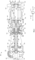
- the thermal transport bus pump 400 includes a secondary flow network having a secondary inlet 476 in the forward bearing housing 428.
- the heat exchange fluid enters the forward bearing housing 428 and flows between the radial portion 472 of the shaft 466 and the thrust bearing assembly 474.
- a first portion of the heat exchange fluid flows around the shaft 466 and into the compressor collector 408 between the impeller 406 and the backplate 432.
- a second portion of the heat exchange fluid in the secondary flow network flows around the shaft 466 towards the barrier can 452.
- the heat exchange fluid flows around the shaft 466 and flows between the axial portion 468 of the shaft 466 and the journal bearing assemblies 470.
- a separation between an aft end of the second magnetic coupling 460 and the barrier can 452 enables the heat exchange fluid to flow past the second magnetic coupling 460 and back through the shaft 466 towards the impeller 406.
- the shaft 466 includes a duct 478 that guides the heat exchange fluid flowing therethrough between the backplate 432 and the impeller 406 causing the heat exchange fluid to enter the compressor collector 408. Accordingly, as the motor 410 drives the rotation of the shaft 438, the impeller 406 pumps the heat exchange fluid through the fluid conduit(s) 402 to an outlet 480.
- the thermal transport bus pump 400 utilizes sCO2 as the heat exchange fluid.
- the sCO2 may reduce in temperature and/or pressure, which move sCO2 to a liquid or gas state.
- a presence of liquid CO2 flowing through the journal bearing assemblies 470, and/or the thrust bearing assembly 474 may adversely affect performance of the respective components and, in turn, the thermal transport bus pump 400.
- the example secondary flow control system e.g., secondary flow control system 800 of FIG. 8
- FIG. 5 illustrates another example thermal transport bus pump 500 (e.g., a straddle mounted fluid pump, a fluid pump, an sCO2 pump, the pump 304 of FIG. 3 , etc.) with which disclosed examples may be implemented.
- the thermal transport bus pump 500 drives a heat exchange fluid (e.g., carbon dioxide) through one or more fluid conduits 502 connected to a flowline (e.g., the thermal transport bus 302 of FIG. 3 ).
- a heat exchange fluid e.g., carbon dioxide
- the pump 500 includes a motor 510 positioned in a motor housing 512, which is at least partially surrounded by a cooling jacket 517 to help prevent a motor 510 in the motor housing 512 from overheating during operations.
- a compressor collector 508 is coupled to the motor housing 512 and a backplate 514 via bolts 516.
- An aft end of the motor housing 512 is coupled to an aft bearing housing 518 and a cover 520 via bolts 522.
- the aft bearing housing 518 and/or the cover 520 is integral with the motor housing 512.
- An example secondary inlet (e.g., secondary flow inlet) 524 of the pump 500 that implements an inlet of a secondary flow network can be defined in the aft bearing housing 518 and/or the cover 520.
- the pump 500 includes a shaft 526 coupled to a rotor 528 of the motor 510 such that the rotor 528 drives a rotation of the shaft 526.
- an aft portion of the shaft 526 e.g., a portion of the shaft positioned aft of the rotor 528, extends through the aft bearing housing 518 and into an indentation 530 (e.g., a groove, a notch, a concavity, etc.) defined in a forward side of the cover 520.
- the aft bearing housing 518 includes a bearing cup 534 that extends forward into the motor housing 512.
- the pump 500 includes a shaft radial bearing 532 (e.g., a first radial bearing) positioned in the bearing cup 534 to radially support the aft portion of the shaft 526.
- the shaft radial bearing 532 can be a foil bearing, a hydrostatic bearing, etc.
- the shaft radial bearing 532 is coupled to the bearing cup 534 via an interference fit (e.g., a press fit), screws, or any other means for coupling that prevents at least a portion of the shaft radial bearing 532 from rotating in the bearing cup 534.
- the heat exchange fluid can lubricate the shaft radial bearing 532 during operation of the pump 500.
- a first labyrinth seal 536 is coupled to a forward end of the bearing cup 534 via screws and/or bolts 538.
- the first labyrinth seal 536 is positioned around the shaft 526 to help control a flow of the heat exchange fluid in the motor housing 512.
- a pressure differential on opposite sides of the first labyrinth seal 536 prevents the heat exchange fluid from flowing past the first labyrinth seal 536 towards an aft end of the pump 500.
- the first labyrinth seal 536 enables the heat exchange fluid that flows between the shaft radial bearing 532 and the shaft 526 to continue to flow towards the forward end of the pump 500.
- the forward portion of the shaft 526 includes a shoulder 560 and a neck 562.
- the shoulder 560 faces the forward end of the pump 500 and defines a transition from the second outer diameter of the shaft 526 forward of the flange 554 to a fifth outer diameter D7 defined by the neck 562 of the shaft 526.
- the fifth outer diameter D7 defines the smallest outer diameter of the shaft 526.
- the fifth outer diameter is approximately equivalent to the first diameter of the bore 558.
- the shaft 526 can include a uniform outer diameter.
- the neck 562 extends into an opening defined in the backplate 514.
- the backplate 514 includes a shoulder brace 564 that is positioned around the shoulder 560 and the neck 562 of the shaft 526. Accordingly, the shoulder brace 564 can help align the shaft 526 in the motor housing 512.
- the greater angular velocity of the impeller 506 enables the pump 500 to expel the heat exchange fluid with an increased flow rate and/or pressure, which can increase a rate at which thermal energy is transferred to and/or from the heat exchange fluid as the heat exchange fluid flows through the heat exchanger(s) 306, 308 of FIG. 3 .
- the improved thermal energy transfer that the pump 500 provides can enable certain components of the aircraft 10 of FIG. 1 and/or the gas turbine engine 100 of FIGS. 1 and/or 2 to operate within increased temperature ranges.
- the impeller bearing 582 mounts the impeller 506 instead of the forward portion of the shaft 526, the impeller bearing 582 enables a size of the motor housing 512 and, thus, a size of the pump 500 to be reduced.
- the size reduction enabled by the impeller bearing 582 can reduce a cost and/or a weight of the pump 500.
- the high density and volumetric heat capacity of CO2 relative to other working fluids makes it more energy-dense, enabling a size reduction of one or components in a pump 304, 400, 500, which can lead to lower capital costs.
- the fluid sensors 818 of FIG. 8 includes an example first sensor 818A having a temperature gauge and a pressure gauge, which enables the sensor 818A to measure a temperature and a pressure of CO2.
- the first sensor 818A is positioned at the primary inlet 401, 501 of the pump 802.
- the controller 816 can obtain the measurements of a CO2 flow as it enters the primary inlet 401, 501 (e.g., via the fluid sensor 818A) and determine a state the CO2 flow prior to the CO2 entering the secondary flowpath 808.
- the controller 816 can utilize sensor data from the fluid sensors 818A to ensure that fluid CO2 that enters the secondary inlet 476, 524 from the secondary flowpath 808 is in a supercritical state rather than in a liquid state. For example, when the controller 816 determines a carbon dioxide flow is in or near a supercritical state, the controller 816 may cause the first thermal valve 814 to open to allow the CO2 flow to pass through the valve 814, along the secondary flowpath 808, and through the secondary inlet 476, 524. In some examples, this is a steady-state condition. In some such examples, the controller 816 may control the first thermal valve 814 to open or close based on a determination that the first thermal valve 814 can move the CO2 flow to a supercritical state.
- the auxiliary reservoir 824 is structured to store sCO2.
- the secondary flow control system 800 can provide sCO2 to the secondary flowpath 808 upon detection of a liquid CO2 flow.
- sCO2 stored in the auxiliary reservoir 824 may be provided to the secondary flowpath 808 at startup of the pump 802.
- a first (e.g., low) threshold that includes a first threshold temperature and a first threshold pressure, which may be a lowest temperature and pressure at which the fluid may be treated as substantially/near-supercritical.
- a second threshold may identify a second threshold temperature associated with a critical pressure at which the fluid may be treated as substantially/near-supercritical.
- a third threshold may identify a second threshold pressure associated with a critical temperature at which the fluid may be treated as substantially/near-supercritical.
- the supercritical threshold(s) 912 are set prior to and/or during operation based on parameters (e.g., materials utilized, pump 304 design, aircraft 10 design, gas turbine engine 100 design, heat exchange fluid, etc.) associated with the thermal management system 300.
- the example maximum pressure value can be adjusted relative to the pressure capacities of the thermal transport bus 302, the pump 304, the heat exchangers 306, 308, the bypass conduit(s) 310, and/or the valves 312, 314.
- the flow monitor circuitry 910 may identify the fluid as a supercritical fluid.
- the flow monitor circuitry 910 identifies the supercritical fluid
- the flow monitor circuitry 910 is configured to direct the supercritical fluid to the recirculation transport bus 806 defining the secondary flowpath 808.
- the flow monitor circuitry 910 determines that the pressure and the temperature of the fluid does not satisfy a supercritical threshold 912
- the flow monitor circuitry 910 is configured to direct the fluid to the bypass conduit 810 defining the bypass flowpath 812.
- the flow monitor circuitry 910 is configured to identify a condition (e.g., temperature and/or pressure condition) to move a fluid to a supercritical state. For example, the flow monitor circuitry 910 may identify a temperature at which to heat the fluid to move the fluid to the supercritical state. In some examples, the flow monitor circuitry 910 may identify a pressure to apply to the fluid to move it to a supercritical state. In some examples, the condition is based on the critical values of CO2. In some examples, the condition is based on the supercritical threshold(s) 912 such that the condition includes temperature and/or pressure values that move the fluid substantially/near supercritical state.
- a condition e.g., temperature and/or pressure condition
- the controller 816 also includes example flow route manager circuitry 914, which is configured to manage the secondary flowpath 808 and the bypass flowpath 812 during operation of the pump 304, 400, 500, 802.
- the flow route manager circuitry 914 may cause the first thermal valve 814 and/or the second thermal valve 822 to move between discrete positions based on a temperature of fluid flowing through a respective valve 814, 822.
- the flow route manager circuitry 914 may cause a pressure valve (e.g., pressure valve 1204, 1206, etc.) to move between discrete positions based on a pressure of fluid flowing through a respective valve 1204, 1206.
- the flow route manager circuitry 914 may cause the heater 826 to apply heat to the fluid based on a temperature of the fluid (e.g., obtained from a sensor(s) 818 via the interface circuitry 904).
- FIG. 10 is a schematic illustration of the example fluid flow diagram of an example secondary flow control system (e.g., secondary flow control system 800 of FIG. 8 ) structured in accordance with teachings of his disclosure.
- the example system 800 illustrated in FIG. 10 includes the example controller 816 to determine a state of an example input flow 1002 of CO2 that enters an example pump 802 (e.g., pump 304, 400, 500).
- the controller 816 may obtain sensor data 1004 (e.g., pressure and temperature measurements) from one or more sensors 818, 818A positioned at a primary inlet 401, 501 of the pump 802.
- sensor data 1004 e.g., pressure and temperature measurements
- the controller 816 determines a corresponding output flow 1006 of CO2 from the pump outlet 480, 580 is associated with a temperature measurement above a critical temperature and a pressure measurement above a critical pressure, indicating the output flow 1006 includes sCO2, the controller 816 actuates the first thermal valve 814 (e.g., via a valve actuator 814A communicatively coupled to the controller 816). This is a steady state condition in which the controller 816 may keep the first thermal valve 814 open until a detection of liquid CO2 in the output flow 1006.
- an sCO2 flow 1008 is driven directly through the secondary flowpath 808 such that sCO2 1012 enters the secondary inlet 476, 524 of the pump 304, 400, 500.
- the controller 816 may determine that CO2 in the input flow 1002 is not in a supercritical phase but rather a liquid phase or a gas phase. In such instances, the controller 816 may determine, based on the pressure and temperature measurements of the input flow 1002, a temperature and/or pressure condition needed to move the CO2 to a supercritical state. Based on the determination, the controller 816 may determine that the first thermal valve 814 can move the output flow 1006 to a supercritical state, a substantially supercritical state, and/or a near-supercritical state. In such instances, the controller 816 may actuate the first thermal valve 814 to direct the output flow 1006 through the secondary flowpath 808.
- the output flow 1006 may experience a pressure change 1010 while traveling from the primary inlet 401, 501, through the pump 802, and to the first thermal valve 814. Accordingly, the controller 816 and/or the first thermal valve 814 can adjust a discrete position of the valve 814 to adjust a pressure of the sCO2 flow 1008 to help ensure the sCO2 flow 1008 is at least a near-supercritical state prior to entering the secondary inlet 476, 524.
- the controller 816 determines the output flow 1006 of CO2 is associated with a temperature measurement below a threshold temperature and/or a pressure measurement below a threshold pressure, indicating that the CO2 is in a liquid phase or a gas phase
- the controller 816 actuates the example second thermal valve 822 (e.g., via a respective valve actuator 822A communicatively coupled to the controller 816).
- the controller 816 causes the first thermal valve 814 to close.
- a corresponding flow 1014 of non-supercritical CO2 is directed to the example bypass circuit (e.g., loop, etc.) 820 via the example bypass conduit 810.
- the controller 816 actuates the bypass circuit 820 to circumvent a portion of the secondary flowpath 808 and move the flow 1014 of non-supercritical CO2 to at least a near-supercritical state.
- a pressure differential associated with the example auxiliary reservoir 824 causes a portion of sCO2 1016 held in the auxiliary reservoir 824 to enter the bypass flowpath 812.
- the portion of sCO2 1016 flows along the bypass conduit 810 and enters the example heater 826.
- a portion 1018 of CO2 entering the heater 826 may not be sCO2 from the auxiliary reservoir 824, but rather CO2 that sat in a respective portion of the bypass conduit 810 for a period of time, thus decreasing in pressure and/or temperature.
- the controller 816 determines a temperature of the CO2 1016, 1018 that enters the heater 826 (e.g., via another temperature gauge of the fluid sensors 818B, a thermometer in the heater 826, etc.). Based on the temperature of the CO2 1016, 1018 the controller 816 may cause the heater 826 to increase in temperature to cause the CO2 1016, 1018 to increase in temperature (e.g., via a respective actuators 826A). Accordingly, the controller 816 can provide sufficient heat to the CO2 1016, 1018 in the heater 826 to ensure that a flow 1022 of CO2 exiting the heater 826 at least a near-supercritical state. The flow 1022 then passes through the open second thermal valve 822 and re-enters the recirculation transport bus 806.
- a portion 1024 of CO2 entering the second thermal valve 822 may not be sCO2 1022 from the heater 826, but rather CO2 that sat in a respective portion of the bypass conduit 810 for a period of time, thus decreasing in pressure and/or temperature.
- the controller 816 and/or the second thermal valve 822 is configured to adjust a discrete position of the valve 822 to adjust a pressure of the CO2 1022, 1024 to ensure the flow of CO2 1022, 1024 is in a supercritical state prior to entering the secondary inlet 476, 524.
- the secondary flow control system 800 can ensure that sCO2 1012 enters the secondary inlet 476, 524 of the pump 304, 400, 500.
- the secondary flow control system 800 can ensure that liquid CO2 does not enter the secondary inlet 476, 524.
- the controller 816 continues to monitor a condition of CO2 that enters and/or exits the pump 802 based on measured parameters obtained from the one or more sensors 818. Accordingly, the secondary flow control system 800 can control a flow of CO2 that enters a secondary inlet 476, 524 and flows through an inner region(s) of the pump 802.
- FIG. 11 illustrates an example valve that may be utilized for an example thermal valve (e.g., first thermal valve 814, second thermal valve 822, etc.) that can be utilized in an example secondary flow control system in accordance with teachings of this disclosure.
- the thermal valve 814, 822 is a thermally activated valve configured to dynamically compensate for varying valve inlet pressures.
- the thermal valve 814, 822 includes a thermal sensing component to identify a temperature of a given flow.
- the thermal valve 814, 822 is caused to move between discrete positions (e.g., self-actuated and/or via the controller 816 and a respective actuator 814A, 822A) in response to temperature changes.
- the thermal valve 814, 814 can be integrated in the recirculation transport bus 806 or the bypass conduit 810, respectively. In some examples, the thermal valve 814, 814 can be mounted non-invasively to the recirculation transport bus 806 or the bypass conduit 810, respectively. The thermal valve 814, 822 thus allows an actuator to be in contact with a fluid flow directly or through thermal conduction to regulate the flow.
- FIG. 12 is a schematic illustration of another example fluid flow diagram of another example secondary flow control system 1200 structured in accordance with teachings of his disclosure.
- the secondary flow control system 1200 of FIG. 12 is coupled to or otherwise integrated with a recirculation of the pump 802 (e.g., the pump 304, a thermal transport bus pump 400, 500, and/or another fluid pump that utilizes a working fluid to lubricate a rotating component during operation).
- the secondary flow control system 1200 of FIG. 12 is similar to the secondary flow control system 800 of FIG. 8 .
- the 12 includes the bypass conduit 810 defining the bypass flowpath 812, the controller 816 to determine a state of an input flow of CO2 (not shown) that enters the pump 802 based on sensor data from one or more sensors 818, 818A (not shown), the example heater 826, and an example thermal valve 814. Further, the controller 816 is configured to direct an output flow 1202 of CO2 based on the state of a corresponding input flow.
- the secondary flow control system 1200 of FIG. 12 includes an example first pressure valve 1204 (e.g., pressure control valve) and an example second pressure valve 1206 (e.g., pressure control valve), each of which is fluidly coupled to the bypass conduit 810. As such, each valve 1204, 1206 may be moved (e.g., by the controller 816) between fully and/or partially opened and/or closed positions to selectively occlude the output flow 1202 of CO2 through the bypass conduit 810.
- the pressure valves 1204, 1206 are actuable flow control structures.
- the first pressure valve 1204 is positioned adjacent the pump outlet 480, 580 to direct the output flow 1202 of CO2.
- the second pressure valve 1206 is positioned downstream of the first pressure valve 1204 (e.g., relative to the secondary inlet 476, 524).
- the first pressure valve 1204 is configured to direct the output flow 1202 of CO2 from the pump outlet 480, 580 to the bypass conduit 810.
- the second pressure valve 1206 is configured to provide a sCO2 1218 from the bypass flowpath 812 to the secondary inlet 476, 524 of the pump 802.
- the bypass conduit 810 of the bypass flowpath 812 is fluidly coupled to and extends between the first and second pressure valves 1204, 1206.
- An example bypass circuit 1210 of the secondary flow control system 1200 of FIG. 12 includes the first pressure valve 1204, an example fluid tank (e.g., CO2 accumulator, etc.) 1212, the heater 826, and the second pressure valve 1206.
- the fluid tank 1212 is structured to store CO2.
- the fluid tank 1212 does not pressurize the CO2 to move the CO2 to a supercritical state. Accordingly, pressure changes to a fluid flow through the bypass circuit 1210 is provided by the pressure valve(s) 1204, 1206.
- the thermal valve 814 is fluidly coupled on the recirculation transport bus 806.
- the secondary flowpath 808 includes the thermal valve 814, and operates in a manner as described in relation to FIG. 8 .
- the controller 816 determines the output flow 1202 is associated with a temperature measurement above a critical and/or threshold temperature and a pressure measurement above a critical and/or threshold pressure, indicating output flow 1202 includes sCO2, the controller 816 actuates the pressure valves 1204 to occlude the output flow 1202 through the bypass conduit 810 and actuates the thermal valve 814 to allow flow therethrough.
- the thermal valve 814 is open, a sCO2 flow 1214 is driven through the valve 814.
- the valve 814 may include sensors 818 to identify a temperature of the sCO2 flow 1214.
- the thermal valve 814 may selectively actuate to increase a pressure of the sCO2 flow 1214 to ensure that a sCO2 flow 1216 exits the thermal valve 814. Accordingly, the thermal valve 814 of the secondary flowpath 808 can help ensure such that sCO2 1218 enters the secondary inlet 476, 524 of the pump 304, 400, 500.
- the pressure valve 1204 may dynamically actuate to adjust a pressure of the output flow 1202 and to adjust a pressure of the flow 1220 non-supercritical CO2. Further, the first pressure valve 1204 drives the flow 1220 of sCO2 to the fluid tank 1212. A pressure differential associated with the fluid tank 1212 causes a portion of sCO2 1222 held in the fluid tank 1212 enter the bypass flowpath 812. The portion of sCO2 1222 flows along the bypass conduit 810 and enters the example heater 826.
- a portion 1224 of CO2 entering the heater 826 may not be sCO2 from the fluid tank 1212, but rather CO2 that sat in a respective portion of the bypass conduit 810 for a period of time, thus decreasing in pressure and/or temperature.
- the controller 816 determines a temperature of the CO2 1222, 1224 that enters the heater 826 (e.g., via another temperature gauge of the fluid sensors 818, a thermometer in the heater 826, etc.). Based on the temperature of the of CO2 1222, 1224 the controller 816 may cause the heater 826 to increase in temperature to cause the CO2 1222, 1224 to increase in temperature. Accordingly, the controller 816 can provide sufficient heat to CO2 1222, 1224 in the heater 826 to ensure that a flow 1226 of CO2 is exiting the heater 826 in a supercritical state.
- the flow of sCO2 1226 then flows through the second pressure valve 1206.
- the second pressure valve 1206 detects a pressure of the sCO2 flow 1226 passing through the valve 1206 and selectively pressurizes the sCO2 flow 1226 such that sCO2 1218 enters the secondary inlet 476, 524 of the pump 304, 400, 500.
- the secondary flow control system 1200 can ensure that liquid CO2 does not enter the secondary inlet 476, 524.
- the controller 816 continues to monitor a condition of CO2 that enters and/or exits the pump 802 based on measured parameters obtained from the one or more sensors 818. Accordingly, the secondary flow control system 800 can control a flow of CO2 that enters a secondary inlet 476, 524 and flows through an inner region(s) of the pump 802.
- FIG. 13 is a schematic illustration of another example fluid flow diagram of another example secondary flow control system 1300 of FIG. 13 structured in accordance with teachings of his disclosure.
- the secondary flow control system 1300 of FIG. 13 is coupled to or otherwise integrated with the pump 802 (e.g., the pump 304, a thermal transport bus pump 400, 500, and/or another fluid pump that utilizes a working fluid to lubricate a rotating component during operation).
- the secondary flow control system 1300 of FIG. 13 which is similar to the secondary flow control systems 800, 1200 of FIGS.
- bypass conduit 810 defining the bypass flowpath 812
- example controller 816 to determine a state of an input flow of CO2 (not shown) that enters the pump 802 based on sensor data from one or more sensors 818 (not shown). Further, the controller 816 is configured to direct an output flow 1302 based on the state of the input flow.
- the secondary flow control system 1300 of FIG. 13 also includes an example flow control valve 1304 positioned on the recirculation transport bus 806.
- the flow control valve 1304 is structure to direct a fluid flow through the valve 1304.
- the flow control valve 1304 may be actuated by the controller 816 (e.g., via an example actuator 1304A). That is, while the flow control valve 1304 is closed, the secondary flowpath 808 is occluded. While the flow control valve 1304 is open, at least a portion of the output flow 1302 can pass through the valve 1304.
- the secondary flow control system 1300 includes an example thermal valve 1306.
- the thermal valve 1306 is similar to the thermal valves 814, 822 of FIG. 8 .
- the thermal valve 1306 of FIG. 14 includes two inlet ports.
- An example first inlet port (e.g., valve inlet) 1306B is fluidly coupled to a downstream end of the bypass conduit 810 and an example second inlet port (e.g., valve inlet) 1306R is fluidly coupled to a portion of recirculation transport bus 806 downstream of the flow control valve 1304.
- An example outlet port (e.g., valve outlet) 1306O of the thermal valve 1306 is fluidly coupled to a portion of the recirculation transport bus 806 between the flow control valve 1304 and the secondary inlet 476, 524 to the pump 802. Accordingly, the thermal valve 1306 of FIG. 13 includes a single thermal valve 1306 as opposed to the two thermal valves 814, 822 of the secondary flow control system 800 of FIG. 8 .
- FIG. 13 includes an example bypass circuit 1308, which includes the first pressure valve 1204 on the bypass conduit 810 adjacent the pump outlet 480, 580, the fluid tank 1212, and the example heater 826. Further, the bypass circuit 1308 includes the thermal valve 1306.
- the controller 816 is configured to cause the thermal valve 1306 to open the first inlet port 1306B (e.g., to actuate the bypass circuit 1308) or the second inlet port 1306R (e.g., via an example actuator 1306A) based on a state of a fluid flow.
- the thermal valve 1306 is self-actuated.
- the thermal valve 1306 is actuated by the controller 816 via a respective actuator 1306A.
- the controller 816 directs the output flow 1302 of CO2 exiting the pump 802 based on the state of the input flow. For example, based on the state of the output flow 1302 of CO2, the controller 816 direct the output flow 1302 to bypass flowpath 812 (e.g., by opening the first pressure valve 1204) or to the secondary flowpath 808 (by opening the flow control valve 1304). Further, the controller 816 may determine a pressure and/or temperature condition to move the output flow 1202 to a supercritical state to determine which flowpath 808, 812 to occlude.
- the controller 816 determines the output flow 1302 is associated with a temperature measurement above a critical and/or threshold temperature and a pressure measurement above a critical and/or threshold pressure, indicating output flow 1302 includes sCO2, the controller 816 actuates the pressure valve 1204 to occlude the output flow 1202 through the bypass conduit 810 and actuates the second inlet port 1306R of the thermal valve 1306 to allow flow therethrough.
- the controller 816 directs the output flow 1302 through the secondary flowpath 808, which provide an sCO2 flow 1310 to the second inlet port 1306R of the thermal valve 1306.
- the controller 816 may actuate the first inlet port 1306B to close such that the sCO2 flow 1310 passes through the second inlet port 1306R of the thermal valve 1306 and through the valve outlet 1306O.
- the thermal valve 1306 selectively actuates the valve outlet 1306O based on a temperature of the sCO2 flow 1310 through the valve to adjust a pressure of the sCO2 flow 1310 to ensure that a sCO2 flow 1312 exits the thermal valve 1306. Accordingly, the thermal valve 1306 of the secondary flowpath 808 can help ensure such that sCO2 1312 enters the secondary inlet 476, 524 of the pump 304, 400, 500.
- the controller 816 determines the output flow 1302 is associated with a temperature measurement below a critical and/or threshold temperature and/or a pressure measurement below a critical and/or threshold pressure, indicating output flow 1302 is in a liquid phase or a gas
- the controller 816 actuates the pressure valve 1204 to allow the output flow 1302 to flow through the bypass flowpath 812.
- the controller 816 circumvents a portion of the secondary flowpath 808 to move the flow 1314 of non-supercritical CO2 to the supercritical state.
- the controller 816 directs the output flow 1302 through the bypass flowpath 812, which provide an sCO2 flow 1312 to the first inlet port 1306B of the thermal valve 1306. Further, the controller 816 actuates the thermal valve 1306 to open the first inlet port 1306B and close the second inlet port 1306R such that the sCO2 flow 1310 passes through the thermal valve 1306 and through the valve outlet 1306O.
- FIGS. 14 and/or 15 Flowcharts representative of example machine readable instructions, which may be executed to configure processor circuitry to implement the controller 816 of FIGS. 8-13 , is shown in FIGS. 14 and/or 15.
- the machine readable instructions may be one or more executable programs or portion(s) of an executable program for execution by processor circuitry, such as the processor circuitry 1612 shown in the example processor platform 1600 discussed below in connection with FIG. 16 .
- the program may be embodied in software stored on one or more non-transitory computer readable storage media such as a compact disk (CD), a floppy disk, a hard disk drive (HDD), a solid-state drive (SSD), a digital versatile disk (DVD), a Blu-ray disk, a volatile memory (e.g., Random Access Memory (RAM) of any type, etc.), or a non-volatile memory (e.g., electrically erasable programmable read-only memory (EEPROM), FLASH memory, an HDD, an SSD, etc.) associated with processor circuitry located in one or more hardware devices, but the entire program and/or parts thereof could alternatively be executed by one or more hardware devices other than the processor circuitry and/or embodied in firmware or dedicated hardware.
- non-transitory computer readable storage media such as a compact disk (CD), a floppy disk, a hard disk drive (HDD), a solid-state drive (SSD), a digital versatile disk (DVD), a Blu
- the machine readable instructions may be distributed across multiple hardware devices and/or executed by two or more hardware devices (e.g., a server and a client hardware device).
- the client hardware device may be implemented by an endpoint client hardware device (e.g., a hardware device associated with a user) or an intermediate client hardware device (e.g., a radio access network (RAN)) gateway that may facilitate communication between a server and an endpoint client hardware device).
- the non-transitory computer readable storage media may include one or more mediums located in one or more hardware devices.
- the example program is described with reference to the flowchart illustrated in FIG. 15 , many other methods of implementing the example controller 816 may alternatively be used.
- any or all of the blocks may be implemented by one or more hardware circuits (e.g., processor circuitry, discrete and/or integrated analog and/or digital circuitry, an FPGA, an ASIC, a comparator, an operational-amplifier (op-amp), a logic circuit, etc.) structured to perform the corresponding operation without executing software or firmware.
- hardware circuits e.g., processor circuitry, discrete and/or integrated analog and/or digital circuitry, an FPGA, an ASIC, a comparator, an operational-amplifier (op-amp), a logic circuit, etc.
- the processor circuitry may be distributed in different network locations and/or local to one or more hardware devices (e.g., a single-core processor (e.g., a single core central processor unit (CPU)), a multi-core processor (e.g., a multi-core CPU, an XPU, etc.) in a single machine, multiple processors distributed across multiple servers of a server rack, multiple processors distributed across one or more server racks, a CPU and/or a FPGA located in the same package (e.g., the same integrated circuit (IC) package or in two or more separate housings, etc.).
- a single-core processor e.g., a single core central processor unit (CPU)
- a multi-core processor e.g., a multi-core CPU, an XPU, etc.
- a CPU and/or a FPGA located in the same package (e.g., the same integrated circuit (IC) package or in two or more separate housings, etc.).
- the machine readable instructions described herein may be stored in one or more of a compressed format, an encrypted format, a fragmented format, a compiled format, an executable format, a packaged format, etc.
- Machine readable instructions as described herein may be stored as data or a data structure (e.g., as portions of instructions, code, representations of code, etc.) that may be utilized to create, manufacture, and/or produce machine executable instructions.
- the machine readable instructions may be fragmented and stored on one or more storage devices and/or computing devices (e.g., servers) located at the same or different locations of a network or collection of networks (e.g., in the cloud, in edge devices, etc.).
- the machine readable instructions may require one or more of installation, modification, adaptation, updating, combining, supplementing, configuring, decryption, decompression, unpacking, distribution, reassignment, compilation, etc., in order to make them directly readable, interpretable, and/or executable by a computing device and/or other machine.
- the machine readable instructions may be stored in multiple parts, which are individually compressed, encrypted, and/or stored on separate computing devices, wherein the parts when decrypted, decompressed, and/or combined form a set of machine executable instructions that implement one or more operations that may together form a program such as that described herein.
- machine readable instructions may be stored in a state in which they may be read by processor circuitry, but require addition of a library (e.g., a dynamic link library (DLL)), a software development kit (SDK), an application programming interface (API), etc., in order to execute the machine readable instructions on a particular computing device or other device.
- a library e.g., a dynamic link library (DLL)
- SDK software development kit
- API application programming interface
- the machine readable instructions may need to be configured (e.g., settings stored, data input, network addresses recorded, etc.) before the machine readable instructions and/or the corresponding program(s) can be executed in whole or in part.
- machine readable media may include machine readable instructions and/or program(s) regardless of the particular format or state of the machine readable instructions and/or program(s) when stored or otherwise at rest or in transit.
- the machine readable instructions described herein can be represented by any past, present, or future instruction language, scripting language, programming language, etc.
- the machine readable instructions may be represented using any of the following languages: C, C++, Java, C#, Perl, Python, JavaScript, HyperText Markup Language (HTML), Structured Query Language (SQL), Swift, etc.
- FIG. 15 may be implemented using executable instructions (e.g., computer and/or machine readable instructions) stored on one or more non-transitory computer and/or machine readable media such as optical storage devices, magnetic storage devices, an HDD, a flash memory, a read-only memory (ROM), a CD, a DVD, a cache, a RAM of any type, a register, and/or any other storage device or storage disk in which information is stored for any duration (e.g., for extended time periods, permanently, for brief instances, for temporarily buffering, and/or for caching of the information).
- executable instructions e.g., computer and/or machine readable instructions
- stored on one or more non-transitory computer and/or machine readable media such as optical storage devices, magnetic storage devices, an HDD, a flash memory, a read-only memory (ROM), a CD, a DVD, a cache, a RAM of any type, a register, and/or any other storage device or storage disk in which information is stored for any duration (e
- non-transitory computer readable medium As used herein, the terms non-transitory computer readable medium, non-transitory computer readable storage medium, non-transitory machine readable medium, and non-transitory machine readable storage medium are expressly defined to include any type of computer readable storage device and/or storage disk and to exclude propagating signals and to exclude transmission media.
- computer readable storage device and “machine readable storage device” are defined to include any physical (mechanical and/or electrical) structure to store information, but to exclude propagating signals and to exclude transmission media.
- Examples of computer readable storage devices and machine readable storage devices include random access memory of any type, read only memory of any type, solid state memory, flash memory, optical discs, magnetic disks, disk drives, and/or redundant array of independent disks (RAID) systems.
- the term "device” refers to physical structure such as mechanical and/or electrical equipment, hardware, and/or circuitry that may or may not be configured by computer readable instructions, machine readable instructions, etc., and/or manufactured to execute computer readable instructions, machine readable instructions, etc.
- FIG. 14 is a flow diagram of an example process 1400 to control or otherwise direct a flow of a working fluid (e.g., a heat exchange fluid, carbon dioxide, etc.) to a secondary flow network.
- a working fluid e.g., a heat exchange fluid, carbon dioxide, etc.
- the process 1400 beings at start-up of an aircraft 10, turbine engine 100, and/or another machine that causes start-up of an example pump 304, 400, 500, 802.
- the process includes identifying sensor data corresponding to a fluid flow. For example, as a heat exchange fluid flows into the pump 304, 400, 500, 802, one or more sensors 818 measure the pressure and temperature of the fluid flow. The sensors 818 can transmit the sensor data to the example controller 816, which obtains the sensor data.
- the sensors 818 are transducers that send an electrical signal to the controller 816, which computes the flow pressure and temperature of the heat exchange fluid.
- the sensors 818 can be venturis, thermocouples, etc., that measure characteristics of the heat exchange fluid to be processed by the controller 816.
- the process includes determining a pressure and/or temperature condition to achieve a substantially supercritical state (e.g., threshold state) of the fluid flow. For example, based on the measured temperature and/or pressure of the fluid flow corresponding to the sensor data, the controller can determine a temperature and/or pressure to apply to the fluid in the fluid flow that would move the fluid to a substantially supercritical state.
- a substantially supercritical state e.g., threshold state
- the controller 816 may be communicatively coupled to the one or more sensors 818
- the controller 816 may obtain sensor data (e.g., via the interface circuitry 904) corresponding to the fluid flow that passes an example sensor 818A to obtain a temperature and a pressure of the fluid.
- the flow monitor circuitry 910 identifies whether the fluid flow is in a threshold state.
- the fluid flow may be in a near-supercritical state and/or a substantially critical state.
- the controller 816 actuates a valve(s) (e.g., first thermal valve 814, first pressure valve 1204, second pressure valve 1206, flow control valve 1304, and/or thermal valve 1306) on the recirculation transport bus 806 to allow flow along the secondary flowpath 808 (block 1508). Control then returns to block 1502. Accordingly, the secondary flow control system 800, 1200, 1300 can continue to ensure that liquid fluid flow does not enter the secondary inlet 476, 524.
- a valve(s) e.g., first thermal valve 814, first pressure valve 1204, second pressure valve 1206, flow control valve 1304, and/or thermal valve 1306
- FIG. 16 is a block diagram of an example processor platform 1600 structured to execute and/or instantiate the machine readable instructions and/or the operations of FIGS. 14 and/or 15 to implement the secondary flow control system 800, 1200, 1300 of FIGS 8-10 , 12 , and/or 13 .
- the processor circuitry 1612 of the illustrated example includes a local memory 1613 (e.g., a cache, registers, etc.).
- the processor circuitry 1612 of the illustrated example is in communication with a main memory including a volatile memory 1614 and a non-volatile memory 1616 by a bus 1618.
- the volatile memory 1614 may be implemented by Synchronous Dynamic Random Access Memory (SDRAM), Dynamic Random Access Memory (DRAM), RAMBUS ® Dynamic Random Access Memory (RDRAM ® ), and/or any other type of RAM device.
- the non-volatile memory 1616 may be implemented by flash memory and/or any other desired type of memory device. Access to the main memory 1614, 1616 of the illustrated example is controlled by a memory controller 1617.
- one or more input devices 1622 are connected to the interface circuitry 1620.
- the input device(s) 1622 permit(s) a user to enter data and/or commands into the processor circuitry 1612.
- the input device(s) 1622 can be implemented by, for example, an audio sensor, a microphone, a camera (still or video), a keyboard, a button, a mouse, a touchscreen, a track-pad, a trackball, an isopoint device, and/or a voice recognition system.
Landscapes
- Engineering & Computer Science (AREA)
- Mechanical Engineering (AREA)
- General Engineering & Computer Science (AREA)
- Physics & Mathematics (AREA)
- Thermal Sciences (AREA)
- Chemical & Material Sciences (AREA)
- Combustion & Propulsion (AREA)
- Structures Of Non-Positive Displacement Pumps (AREA)
Abstract
Description
- This disclosure relates generally to fluid pumps and, more particularly, to methods, systems, and apparatus to control a fluid provided to components in a fluid pump of a closed loop system.
- Aircraft typically include various accessory systems supporting operation of the aircraft(s) and/or its gas turbine engine(s), such as (but not limited to) a lubrication system that lubricates components of the engine(s), an engine cooling system that provides cooling air to engine components, an environmental control system that provides cooled air to the cabin of the aircraft(s), and/or the like. Such aircraft may include a thermal management system to add or remove heat from a fluid (e.g., oil, air, etc.) during operation of these accessory systems. The thermal management system can include a pump to drive a heat transfer fluid through heat exchangers such that heat is added to and/or removed from the heat exchange fluid.
-
-
FIG. 1 is a side view of an example aircraft. -
FIG. 2 is a schematic cross-sectional view of an example gas turbine engine of an aircraft. -
FIG. 3 is a schematic diagram of an example thermal management system for transferring heat between fluids. -
FIGS. 4 and5 illustrate example thermal transport bus pumps with which disclosed example may be implemented. -
FIG. 6 illustrates an example fluid flow diagram associated with the thermal transport bus pump ofFIG. 5 . -
FIG. 7 is an example temperature-pressure phase diagram for carbon dioxide illustrating phases of carbon dioxide at different conditions. -
FIG. 8 is a schematic illustration of an example secondary flow control system configured in accordance with teachings of this disclosure for controlling a state of fluid that enters a secondary flow network for lubricating rotating components in a fuel pump. -
FIG. 9 is a block diagram of an example implementation of example secondary flow control systems disclosed herein. -
FIG. 10 illustrates an example fluid flow diagram associated with the example secondary flow control system ofFIG. 8 in accordance with teachings of this disclosure. -
FIG. 11 is an illustration of an example thermal valve that may be used in example secondary flow control systems disclosed herein. -
FIG. 12 illustrates another example fluid flow diagram associated with another example secondary flow control system structured in accordance with teachings of this disclosure. -
FIG. 13 illustrates another example fluid flow diagram associated with another example secondary flow control system structured in accordance with teachings of this disclosure. -
FIG. 14 is a flow diagram of an example process to control a fluid provided to a secondary flow network of a pump. -
FIG. 15 is flowchart representative of example machine readable instructions and/or example operations that may be executed by example processor circuitry to implement the example secondary flow control system(s) ofFIGS. 8-10 ,11 , and/or12 . -
FIG. 16 is a block diagram of an example processing platform including processor circuitry structured to execute the example machine readable instructions and/or the example operations ofFIG. 15 to implement the example secondary flow control system(s)FIG. 8-10 ,11 , and/or12 . - In general, the same reference numbers will be used throughout the drawing(s) and accompanying written description to refer to the same or like parts. The figures are not to scale.
- As used herein, unless otherwise stated, the term "above" describes the relationship of two parts relative to Earth. A first part is above a second part, if the second part has at least one part between Earth and the first part. Likewise, as used herein, a first part is "below" a second part when the first part is closer to the Earth than the second part. As noted above, a first part can be above or below a second part with one or more of: other parts therebetween, without other parts therebetween, with the first and second parts touching, or without the first and second parts being in direct contact with one another.
- As used in this patent, stating that any part (e.g., a layer, film, area, region, or plate) is in any way on (e.g., positioned on, located on, disposed on, or formed on, etc.) another part, indicates that the referenced part is either in contact with the other part, or that the referenced part is above the other part with one or more intermediate part(s) located therebetween.
- As used herein, connection references (e.g., attached, coupled, connected, and joined) may include intermediate members between the elements referenced by the connection reference and/or relative movement between those elements unless otherwise indicated. As such, connection references do not necessarily infer that two elements are directly connected and/or in fixed relation to each other. As used herein, stating that any part is in "contact" with another part is defined to mean that there is no intermediate part between the two parts.
- Unless specifically stated otherwise, descriptors such as "first," "second," "third," etc., are used herein without imputing or otherwise indicating any meaning of priority, physical order, arrangement in a list, and/or ordering in any way, but are merely used as labels and/or arbitrary names to distinguish elements for ease of understanding the disclosed examples. In some examples, the descriptor "first" may be used to refer to an element in the detailed description, while the same element may be referred to in a claim with a different descriptor such as "second" or "third." In such instances, it should be understood that such descriptors are used merely for identifying those elements distinctly that might, for example, otherwise share a same name.
- Approximating language, as used herein throughout the specification and claims, is applied to modify any quantitative representation that could permissibly vary without resulting in a change in the basic function to which it is related. Accordingly, a value modified by a term or terms, such as "about", "approximately", and "substantially", are not to be limited to the precise value specified. In at least some instances, the approximating language may correspond to the precision of an instrument for measuring the value, or the precision of the methods or machines for constructing or manufacturing the components and/or systems. For example, the approximating language may refer to being within a ten percent margin.
- The terms "forward" and "aft" refer to relative positions within a gas turbine engine, pump, or vehicle, and refer to the normal operational attitude of the gas turbine engine, pump, or vehicle. For example, with regard to a gas turbine engine, forward refers to a position closer to an engine inlet and aft refers to a position closer to an engine nozzle or exhaust. Further, with regard to a pump, forward refers to a position closer to a pump inlet and aft refers to a position closer to an end of the pump opposite the inlet.
- The terms "upstream" and "downstream" refer to the relative direction with respect to a flow in a pathway. For example, with respect to a fluid flow, "upstream" refers to the direction from which the fluid flows, and "downstream" refers to the direction to which the fluid flows.
- As used herein, "radially" is used to express a point or points along a radial vector originating at a central axis of a rotating body and pointing perpendicularly outward from the central axis.
- As used herein, in the context of describing the position and/or orientation of a first object relative to a second object, the term "substantially orthogonal" encompasses the term orthogonal and more broadly encompasses a meaning whereby the first object is positioned and/or oriented relative to the second object at an absolute angle of no more than five degrees (5°) from orthogonal. For example, a bearing that is substantially orthogonal to an axis is positioned and/or oriented relative to the axis at an absolute angle of no more than five degrees (5°) from orthogonal.
- As used herein, in the context of describing actuation of a valve, the term "actuate" refers to opening or closing the valve and/or a port thereof. As used herein, in the context of describing a valve, the terms "open" and "close" encompass the action of opening or closing, respectively, the valve and/or the port thereof and more broadly encompasses a condition (e.g., opened or closed, respectively) of the valve and/or the port thereof which results from the action(s). To close a valve is to position a valve such that fluid is prevented from flowing through the valve. As used herein, in the context of describing the valve and/or the port thereof, the term "open" encompasses a number of discrete positions such that fluid can flow through the valve (e.g., fully opened, partially opened, etc.) and/or the port thereof. In some examples, the open valve is dynamic such that the valve can move between the discrete positions (e.g., based on a condition of the fluid, etc.) to control thermal fluid pressure.
- As used herein, in the context of describing a state of a fluid (e.g., fluid carbon dioxide), the term "supercritical" and "supercritical state" describe a supercritical state whereby the fluid is at or above a critical temperature and critical pressure. In some examples, a fluid in a substantially supercritical state (e.g., whereby the fluid is at or within 5% of the critical temperature and at or within 5% of the critical pressure) and/or a near-supercritical state (e.g., whereby the fluid is within a 5% range of a critical temperature and/or within a 5% range of a critical pressure) are treated as a supercritical fluid in view of diminishing returns of causing a fluid to move to a fully supercritical state.
- The terms "state" and "phase" are used below to describe a form of matter (e.g., carbon dioxide). A state of matter refers to a form of matter at a given temperature and a pressure. A phase of matter refers to a set of equilibrium states demarcated in terms of state variables such as pressure and temperature. As discussed herein, the terms state and phase are used interchangeable to describe a form of a given portion of matter at a given moment. At a given temperature and pressure, a substance can exist mainly in one of four major states/phases of matter: solid, liquid, gas, and supercritical fluid. The term "non-liquid fluid" is used below to describe matter that is not in a liquid state/phase or a solid state/phase.
- "Including" and "comprising" (and all forms and tenses thereof) are used herein to be open ended terms. Thus, whenever a claim employs any form of "include" or "comprise" (e.g., comprises, includes, comprising, including, having, etc.) as a preamble or within a claim recitation of any kind, it is to be understood that additional elements, terms, etc., may be present without falling outside the scope of the corresponding claim or recitation. As used herein, when the phrase "at least" is used as the transition term in, for example, a preamble of a claim, it is open-ended in the same manner as the term "comprising" and "including" are open ended. The term "and/or" when used, for example, in a form such as A, B, and/or C refers to any combination or subset of A, B, C such as (1) A alone, (2) B alone, (3) C alone, (4) A with B, (5) A with C, (6) B with C, or (7) A with B and with C. As used herein in the context of describing structures, components, items, objects and/or things, the phrase "at least one of A and B" is intended to refer to implementations including any of (1) at least one A, (2) at least one B, or (3) at least one A and at least one B. Similarly, as used herein in the context of describing structures, components, items, objects and/or things, the phrase "at least one of A or B" is intended to refer to implementations including any of (1) at least one A, (2) at least one B, or (3) at least one A and at least one B. As used herein in the context of describing the performance or execution of processes, instructions, actions, activities and/or steps, the phrase "at least one of A and B" is intended to refer to implementations including any of (1) at least one A, (2) at least one B, or (3) at least one A and at least one B. Similarly, as used herein in the context of describing the performance or execution of processes, instructions, actions, activities and/or steps, the phrase "at least one of A or B" is intended to refer to implementations including any of (1) at least one A, (2) at least one B, or (3) at least one A and at least one B.
- As used herein, singular references (e.g., "a", "an", "first", "second", etc.) do not exclude a plurality. The term "a" or "an" object, as used herein, refers to one or more of that object. The terms "a" (or "an"), "one or more", and "at least one" are used interchangeably herein. Furthermore, although individually listed, a plurality of means, elements or method actions may be implemented by, e.g., the same entity or object. Additionally, although individual features may be included in different examples or claims, these may possibly be combined, and the inclusion in different examples or claims does not imply that a combination of features is not feasible and/or advantageous.
- As used herein, the phrase "in communication," including variations thereof, encompasses direct communication and/or indirect communication through one or more intermediary components, and does not require direct physical (e.g., wired) communication and/or constant communication, but rather additionally includes selective communication at periodic intervals, scheduled intervals, aperiodic intervals, and/or one-time events.
- As used herein, "processor circuitry" is defined to include (i) one or more special purpose electrical circuits structured to perform specific operation(s) and including one or more semiconductor-based logic devices (e.g., electrical hardware implemented by one or more transistors), and/or (ii) one or more general purpose semiconductor-based electrical circuits programmable with instructions to perform specific operations and including one or more semiconductor-based logic devices (e.g., electrical hardware implemented by one or more transistors). Examples of processor circuitry include programmable microprocessors, Field Programmable Gate Arrays (FPGAs) that may instantiate instructions, Central Processor Units (CPUs), Graphics Processor Units (GPUs), Digital Signal Processors (DSPs), XPUs, or microcontrollers and integrated circuits such as Application Specific Integrated Circuits (ASICs). For example, an XPU may be implemented by a heterogeneous computing system including multiple types of processor circuitry (e.g., one or more FPGAs, one or more CPUs, one or more GPUs, one or more DSPs, etc., and/or a combination thereof) and application programming interface(s) (API(s)) that may assign computing task(s) to whichever one(s) of the multiple types of processor circuitry is/are best suited to execute the computing task(s).
- Aircraft often include a thermal management system to transfer heat to/from accessory systems of a gas turbine engine. The thermal management system may include a fluid pump coupled to one or more heat exchangers via a thermal transport bus (e.g., a conduit, flowpath, etc.). The fluid pump drives a fluid (e.g., a heat transfer fluid, a working fluid such as fuel, oil, air, supercritical carbon dioxide, etc.) between the accessory systems and/or engine components. During operation of the thermal transport system, the heat transfer fluid can absorb heat from a heat source(s) and/or transfer heat to a heat sink(s) such that the fluid absorbs heat from and/or transfers heat to the systems and/or components.
- In some examples, the fluid pump is a centrifugal fluid pump that moves the fluid by converting rotational kinetic energy of an impeller to hydrodynamic energy of a flowing fluid. The impeller is provided a change in rotational kinetic energy from an electric motor applying mechanical work to an impeller shaft coupled to the impeller and to a rotor (e.g., motor shaft) of the electric motor. The rotor can be coupled to the impeller shaft axially (e.g., via a magnetic coupling) or radially (e.g., via a gearing assembly, etc.). The rotor is provided a change in mechanical work over a period of time (i.e., mechanical power) from a stator in the electric motor applying electromagnetic forces to the rotor in the form of torque. In other words, the torque and angular velocity of the rotor is transferred to the impeller shaft, and ultimately, to the impeller, which draws the heat exchange fluid into an inlet and accelerates the heat exchange fluid radially outward into an outlet.
- The centrifugal fluid pump typically includes one or more bearings (e.g., radial bearings and/or thrust bearings) to support a load applied by the rotor, the impeller shaft, and/or another component of the fluid pump. Bearings constrain relative motion of a shaft(s) to an axis of rotation defined by the shaft, enabling free motion of the shaft about the axis rotation. The load can be applied to the bearing in a radial direction (e.g., orthogonal to the bearing's axis of rotation) or an axial direction (e.g., a thrust acts parallel to the bearing's axis of rotation). For example, the thrust bearing may include a foil bearing positioned around a thrust disc to prevent or otherwise reduce axial movement of the shaft.
- Centrifugal fluid pumps in high pressure applications (e.g., aircrafts, gas turbine engines, etc.) often include fluid bearings (e.g., foil bearings, journal bearings, etc.), which are non-contact bearings that rely on a pressurized fluid to support the load and reduce friction. In some examples, the centrifugal fluid pumps implement closed loop systems in which the heat exchange fluid flowing through the pump is contained in a system of conduits (e.g., a conduit system, a pipeline system, flowpath(s), flowline(s), etc.) that prevent other fluids from transferring into or out of the system of conduits. In some examples, the centrifugal fluid pump includes a recirculation loop (e.g., a recirculation circuit, a secondary system, a lubrication system, etc.) that is configured to provide at least a portion of a working fluid to internal components of the fluid pump. For example, the centrifugal fluid pump can include a primary flow network (e.g., loop, flowline(s), etc.) to drive the heat exchange fluid to the thermal transport bus to support an operation of the aircraft and a secondary flow network (e.g., loop, flowline(s), etc.) to drive the heat exchange fluid through the fluid pump to lubricate the fluid bearings (e.g., radial bearings, thrust bearings, etc.) and reduce frictional forces between rotating elements within those bearings. The primary flow network may include conduits fluidly coupled to the thermal transport bus. The secondary flow network may include a flowpath(s) and/or flowline(s) within the pump to allow pressurized fluid to flow through the fluid bearings and/or other internal components of the pump.
- The recirculation loop can include a recirculation transport bus (e.g., secondary conduit, flowline, duct, etc.) fluidly coupled to the secondary flow network via a secondary inlet of the fluid pump. In some examples, the recirculation transport bus is fluidly coupled between an outlet of the pump (e.g., directly to the outlet or to a portion of the thermal transport bus extending from the outlet) and the secondary inlet of the pump. Thus, the centrifugal fluid pump may be configured to tap a portion of the heat exchange fluid flowing from the outlet of the pump to provide pressurized fluid to the secondary flow network to support the fluid bearings and/or other rotating components of the pump (e.g., the impeller).
- In some examples, the pump can include expeller vanes to drive the heat exchange fluid from internal portions of a pump housing to the pump outlet. In some examples, expeller vanes protrude from an aft side of the impeller and function similarly to impeller vanes. That is, the heat exchange fluid approaches the expeller vanes along a central axis and accelerates radially outward from the expeller vanes. Thus, the secondary flow network and the expeller vanes can implement a lubricating circuit from the pump outlet to the fluid bearing(s) and back to the expeller vanes to provide a continuous flow of the fluid to the load bearings.
- During operation of the pump, axial thrust of the impeller shaft can act in forward or aft directions based on interactions between the impeller vanes/expeller vanes and the fluid. The heat exchange fluid enters through a primary inlet of the pump along a central/rotating/shaft axis toward the impeller, which includes the impeller vanes to accelerate the fluid radially outward into a pump outlet. Fluid pressure on a forward portion of the impeller can transfer aft axial loads to the impeller shaft in the aft direction. Similarly, a portion of the fluid that enters the secondary inlets flows forward along the axis of rotation of the impeller shaft and builds up pressure on an aft portion of the impeller (e.g., the expeller). Fluid pressure on the aft portion of the impeller can transfer forward loads to the impeller shaft in the forward direction. When the forward and aft axial loads are of equal values and act in opposite directions, the pump is said to be "thrust balanced." Accordingly, the second flow network can provide thrust balance for the impeller of the centrifugal fluid pump.
- In some examples, the thermal management system uses supercritical, carbon dioxide (e.g., sCO2) as the heat exchange fluid due to its low viscosity and high specific heat, which makes sCO2 more thermally conductive than other heat exchange fluids (e.g., water, air, etc.). Supercritical carbon dioxide is carbon dioxide held at or above a critical temperature and a critical pressure, allowing it to take on properties of a gas and a liquid, resulting in a low (e.g., gas-like) viscosity and high (fluid-like) density. In some examples, the thermal management system uses supercritical carbon dioxide, substantially supercritical carbon dioxide and/or near-supercritical carbon dioxide as the heat exchange fluid. In some examples, the thermal management system uses non-liquid fluid carbon dioxide as the heat exchange fluid.
- Performance of the centrifugal fluid pump and/or components therefore may increase when working carbon dioxide is in a supercritical phase and/or another non-liquid fluid phase, and decreases when working carbon dioxide is in a liquid phase. For example, a presence of liquid carbon dioxide flowing around a non-liquid fluid bearing may adversely affect performance of the bearing and, in turn, the fluid pump. In some examples, the presence of liquid carbon dioxide may result in viscous draft (e.g., hydrodynamic drag, windage loss, etc.), issues with film thickness/stiffness, etc. Viscous drag refers to a reduction in efficiency due to a drag forces (e.g., friction) between a liquid and a surface (the shaft, the bearing, a housing supporting the bearing, etc.), which decreases fluid velocity relative to the surface. Non-liquid fluid bearings can utilize a thin film of pressurized fluid (e.g., a non-liquid fluid) to provide a low friction load-bearing interface (e.g., a bearing clearance) between surfaces of the fluid pump (e.g., a shaft and a rotor). Bearing failure can result from a breakdown in film (e.g., a reduction in bearing clearance) separating the rotating component from the nonrotating component. In some examples, a small change in the film thickness can result in a comparatively large reduction in a load carrying capacity of the non-liquid fluid bearing.
- Example methods, systems, and apparatus are disclosed herein provide control of a fluid flow to be provided to a rotating component (e.g., a fluid bearing, an impeller, etc.) of a fluid pump in a closed loop or semi-closed fluid system. Disclosed examples may be applied to a thermal management system that uses a heat transfer fluid to transfer thermal energy between heat exchangers (e.g., a heat source heat exchanger and/or heat sink heat exchanger). Disclosed examples may be applied to a closed loop centrifugal fluid pump that provides a pressurized fluid to a thermal transport bus via a primary flow network and to operational components of the pump via a secondary flow network within the pump. In some examples, the heat transfer fluid is a supercritical fluid.
- Examples disclosed herein may be applied to a fluid pump that utilizes supercritical carbon dioxide (sCO2) as a working fluid (e.g., an sCO2 pump). The sCO2 pump may be used to implement an advanced Brayton cycle, which is a supercritical recompression thermodynamic cycle based on a working fluid (e.g., sCO2, etc.). The unique properties of sCO2 present advantages for closed-loop power generation, such as those described herein, and can be applied to various power generation applications increase efficiency and power output.
- Examples disclosed herein enable manufacture of an example flow control system for a secondary (e.g., recirculation) loop of a closed loop fluid pump. In some examples, the recirculation loop includes an example secondary flow network defined by a flowpath(s) through operational components of the fluid pump and an example recirculation transport bus that defines an example secondary flowpath from an outlet of the fluid pump to a secondary inlet of the fluid pump that leads to the secondary flow network. Example secondary flow control systems disclosed herein are configured to prevent or otherwise limit liquid carbon dioxide from entering the secondary flow network. Disclosed examples may be coupled or otherwise integrated with recirculation loops of centrifugal pumps.
- Example secondary flow control systems disclosed herein include one or more sensors to detect a temperature(s) and pressure(s) of fluid carbon dioxide relative to the recirculation loop during operation of the centrifugal fluid pump. For example, one or more sensors may be positioned relative to an inlet and/or outlet of the centrifugal fluid pump such that temperature and pressure measurements of fluid carbon dioxide can be obtained prior to entrance to a secondary flowpath leading to the secondary flow network. In some examples, the secondary flowpath is defined by a conduit (e.g., a recirculation transport bus, duct, pipe, etc.) fluidly coupled between an outlet of the fluid pump and a secondary inlet of the fluid pump that defines an inlet of the secondary flow network.
- Certain examples include a controller (e.g., controller circuitry, etc.) to control components of the flow control system. In some examples, the controller can determine a state of fluid carbon dioxide based on sensor data from the one or more sensors. For example, the state of fluid carbon dioxide can be determined based on a measured temperature and a measured pressure of the fluid carbon dioxide (e.g., based on a temperature-pressure phase diagram). Certain examples provide for conversion of liquid carbon dioxide entering the secondary flowpath to a supercritical state such that sCO2 is provided to the secondary flow network rather than the liquid carbon dioxide.
- Example secondary flow control systems disclosed herein include one or more valves to direct fluid carbon dioxide entering the secondary flowpath. Based on a phase of fluid carbon dioxide entering the secondary flowpath, the one or more valves may allow the fluid carbon dioxide to flow through the secondary flowpath to the secondary inlet, or may direct the fluid carbon dioxide to an example bypass (e.g., conversion) flowpath defined by an example bypass conduit (e.g., flowline, pipe, duct, etc.). For example, the flow control system may cause detected sCO2 to flow through the secondary flowpath directly to the secondary flow network while causing detected liquid CO2 to flow through the bypass flowpath. Certain examples drive liquid CO2 entering the bypath flowpath towards a pressure tank(s), a heater(s), a pressure valve(s), a thermal valve(s), etc. positioned along the bypass flowpath to transform the liquid CO2 into sCO2. Upon reaching the supercritical phase, certain example secondary flow control systems allow the sCO2 to return to the secondary flowpath to be provided to the secondary flow network and/or stored in a pressure tank for future use.
- During operation, the centrifugal fluid pump may reach a steady state at which heat applied from components of the thermal management system is sufficient to convert liquid carbon dioxide to a supercritical state. However, while the pump is powered down, a temperature and/or pressure of working carbon dioxide may reduce, transforming sCO2 to liquid form. Accordingly, liquid carbon dioxide is often present in the central fluid pump during start-up of the pump (e.g., of the aircraft/engine). Certain examples may help ensure that fluid carbon dioxide that enters into the secondary flow network is in a supercritical phase rather than in a liquid phase to improve performance of a bearing(s) in the fluid pump. Certain examples may help ensure that liquid carbon dioxide inside the fluid pump (e.g., during operation, during start-up, etc.) does not enter an inlet of an impeller. Certain examples may improve reliability of foil bearings in a fluid pump.
- Examples are disclosed below in relation to a different types of centrifugal fluid pumps. However, in alternative examples, the fluid pumps may vary in number and/or type. For example, disclosed examples can be applied to applications for which a fluid state change may be needed during engine startup. While examples disclosed herein are applied to fluid pumps having fluid carbon dioxide as the working fluid, disclosed examples can be applied to other systems having other types of working fluids in additional or alternative examples such that the systems can achieve a critical temperature of the working fluid and the working fluid is associated with a critical pressure below a maximum pressure of the systems. For example, the working fluid can be nitrogen and/or other fluids for which a critical point to be achieved is reasonable in view of a given application.
- In the following detailed description, reference is made to the accompanying drawings that form a part hereof, and in which is shown by way of illustration specific examples that may be practiced. These examples are described in sufficient detail to enable one skilled in the art to practice the subject matter, and it is to be understood that other examples may be utilized. The following detailed description is therefore, provided to describe an exemplary implementation and not to be taken limiting on the scope of the subject matter described in this disclosure. Certain features from different aspects of the following description may be combined to form yet new aspects of the subject matter discussed below.
- Referring now to the drawings, wherein identical numerals indicate the same elements throughout the figures,
FIG. 1 is a side view of one embodiment of anaircraft 10 that may implement the examples disclosed herein. As shown, in several embodiments, theaircraft 10 includes afuselage 12 and a pair of wings 14 (one is shown) extending outward from thefuselage 12. In the illustrated embodiment, agas turbine engine 100 is supported on eachwing 14 to propel the aircraft through the air during flight. Additionally, as shown, theaircraft 10 includes avertical stabilizer 16 and a pair of horizontal stabilizers 18 (one is shown). However, in alternative embodiments, theaircraft 10 may include any other suitable configuration, such as any other suitable number or type of engines. - Furthermore, the
aircraft 10 may include athermal management system 300 for transferring heat between fluids supporting the operation of theaircraft 10. More specifically, theaircraft 10 may include one or more accessory systems configured to support the operation of theaircraft 10. For example, in some examples, such accessory systems include a lubrication system that lubricates components of theengines 100, a cooling system that provides cooling air to components of theengines 100, an environmental control system that provides cooled air to the cabin of theaircraft 10, and/or the like. In such examples, thethermal management system 300 is configured to transfer heat to and/or from one or more fluids supporting the operation of the aircraft 10 (e.g., the oil of the lubrication system, the air of the cooling system and/or the environmental control system, and/or the like) from and/or to one or more other fluids supporting the operation of the aircraft 10 (e.g., the fuel supplied to the engines 100). However, in alternative examples, thethermal management system 300 may be configured to transfer heat between any other suitable fluids supporting the operation of theaircraft 10. Further, the configuration of theaircraft 10 described above and shown inFIG. 1 is provided only to place the present subject matter in an exemplary field of use. Thus, the present subject matter may be readily adaptable to any manner of aircraft and/or any other suitable heat transfer application. -
FIG. 2 is a schematic cross-sectional view of one embodiment of agas turbine engine 100. In the illustrated example ofFIG. 2 , theengine 100 extends along anaxial centerline 102 and includes afan 104, a low-pressure (LP)spool 106, and a high pressure (HP)spool 108 at least partially encased by anannular nacelle 110. Thefan 104 may include afan rotor 112 and a plurality of fan blades 114 (one is shown) circumferentially spaced apart and extend radially outward from thefan rotor 112. The LP and HP spools 106, 108 are positioned downstream from thefan 104 along theaxial centerline 102. As shown, theLP spool 106 is rotatably coupled to thefan rotor 112, permitting theLP spool 106 to rotate thefan blades 114. A plurality of outlet guide vanes (e.g., struts) 116 extend radially between anouter casing 118 surrounding the LP and HP spools 106, 108 and thenacelle 110. As such, theoutlet guide vanes 116 support thenacelle 110 relative to theouter casing 118 such that theouter casing 118 and thenacelle 110 define abypass airflow passage 120 positioned therebetween. - The
outer casing 118 generally surrounds or encases, in serial flow order, acompressor section 122, acombustion section 124, aturbine section 126, and anexhaust section 128. Thecompressor section 122 may include a low-pressure (LP)compressor 130 of theLP spool 106 and a high-pressure (HP)compressor 132 of theHP spool 108 positioned downstream from theLP compressor 130. Theturbine section 126 may include a high-pressure (HP)turbine 138 of theHP spool 108 and a low-pressure (LP)turbine 140 of theLP spool 106 positioned downstream from theHP turbine 138. Additionally, theLP spool 106 includes a low-pressure (LP)shaft 146 and theHP spool 108 includes a high pressure (HP)shaft 148 positioned concentrically around theLP shaft 146. - As mentioned above, the
aircraft 10 may include athermal management system 300 for transferring heat between fluids supporting the operation of theaircraft 10. In this respect, thethermal management system 300 may be positioned within theengine 100. For example, as shown inFIG. 2 , thethermal management system 300 is positioned within theouter casing 118 of theengine 100. However, in alternative examples, thethermal management system 300 may be positioned at any other suitable location within theengine 100. - Furthermore, in some examples, the
engine 100 defines a third-stream flow path 170. In general, the third-stream flow path 170 extends from a compressedair flow path 133 defined by thecompressor section 122 to thebypass airflow passage 120. In this respect, the third-stream flow path 170 allows a portion ofcompressed air 158 from thecompressor section 122 to bypass thecombustion section 124. The third-stream flow path 170 may be configured to selectively remove a portion ofcompressed air 158 from the compressed air flow path via one or more variable guide vanes, nozzles, or other actuable flow control structures (e.g., a variable bleed valve). In some example, thethermal management system 300 may transfer heat to the air flowing through the third-stream flow path 170. - In the illustrated example, the
engine 100 is configured as a high-bypass turbofan engine. However, in alternative embodiments, theengine 100 may be configured as a propfan engine, a turbojet engine, a turboprop engine, a turboshaft gas turbine engine, or any other suitable type of gas turbine engine. The configuration of thegas turbine engine 100 described above and shown inFIG. 2 is provided only to place the present subject matter in an example field of use. Thus, the present subject matter may be readily adaptable to any manner of gas turbine engine configuration, including other types of aviation-based gas turbine engines, marine-based gas turbine engines, and/or land-based/industrial gas turbine engines. -
FIG. 3 is a schematic view of an example implementation of thethermal management system 300 for transferring heat between fluids. In general, thethermal management system 300 will be discussed in the context of theaircraft 10 and thegas turbine engine 100 described above and shown inFIGS. 1 and2 . However, the disclosedthermal management system 300 may be implemented within any aircraft having any other suitable configuration, any gas turbine engine having any other suitable configuration, and/or other high-pressure applications that utilize a thermal transport system. - As shown, the
thermal management system 300 includes athermal transport bus 302. In some examples, thethermal transport bus 302 defines a primary flowpath. In some examples, thethermal transport bus 302 is configured as one or more fluid conduits through which a fluid (e.g., a heat exchange fluid such as carbon dioxide) flows. As will be described below, the heat exchange fluid flows through various heat exchangers such that heat is added to and/or removed from the heat exchange fluid. In this respect, the heat exchange fluid may be any suitable fluid, such as sCO2. Moreover, in such examples, thethermal management system 300 includes apump 304 configured to pump the heat exchange fluid through thethermal transport bus 302. - The
thermal management system 300 ofFIG. 3 includes one or more heatsource heat exchangers 306 arranged along thethermal transport bus 302. The heat source heat exchanger(s) 306 is fluidly coupled to thethermal transport bus 302 such that the heat exchange fluid can flow through the heat source heat exchanger(s) 306. In this respect, the heat source heat exchanger(s) 306 is configured to transfer heat from fluids supporting the operation of theaircraft 10 to the heat exchange fluid, thereby cooling the fluids supporting the operation of theaircraft 10. Thus, the heat source heat exchanger(s) 306 adds heat to the heat exchange fluid. AlthoughFIG. 3 illustrates two heatsource heat exchangers 306, thethermal management system 300 may include a single heatsource heat exchanger 306 or three or more heatsource heat exchangers 306. - The heat source heat exchanger(s) 306 may correspond to any suitable heat exchanger(s) that cools a fluid supporting the operation of the
aircraft 10. For example, at least of one of the heatsource heat exchangers 306 may be a heat exchanger(s) of the lubrication system(s) of the engine(s) 100. In such an example, this heat exchanger(s) 306 transfers heat from the oil lubricating the engine(s) 100 to the heat transfer fluid. In some examples, at least one of the heatsource heat exchangers 306 may be a heat exchanger(s) of the cooling system of the engine(s) 100. In such examples, the heat exchanger(s) 306 transfers heat from the cooling air bled from the compressor section(s) 122 (or a compressor discharge plenum) of the engine(s) 100 to the heat transfer fluid. In alternative examples, the heat source heat exchanger(s) 306 may correspond to any other suitable heat exchangers that cool a fluid supporting the operation of theaircraft 10. - Furthermore, the
thermal management system 300 ofFIG. 3 includes a plurality of heatsink heat exchangers 308 arranged along thethermal transport bus 302. The heatsink heat exchangers 308 are fluidly coupled to thethermal transport bus 302 such that the heat exchange fluid can flow through the heatsink heat exchangers 308. In this respect, the heatsink heat exchangers 308 are configured to transfer heat from the heat exchange fluid to other fluids supporting the operation of theaircraft 10, which heats the other fluids supporting the operation of theaircraft 10. In other words, the heatsink heat exchangers 308 remove heat from the heat exchange fluid. AlthoughFIG. 3 illustrates two heatsink heat exchangers 308, thethermal management system 300 may include three or more heatsink heat exchangers 308. - The heat
sink heat exchangers 308 may correspond to any suitable heat exchangers that heat a fluid supporting the operation of theaircraft 10. For example, at least of one of the heatsink heat exchangers 308 is a heat exchanger(s) of the fuel system(s) of the engine(s) 100. In such an example, the fuel system heat exchanger(s) 308 transfers heat from the heat transfer fluid to the fuel supplied to the engine(s) 100. In some examples, at least one of the heatsink heat exchangers 308 may be a heat exchanger(s) in contact withair 156 flowing through the bypass airflow passage(s) 120 of the engine(s) 100. In such an example, the heat exchanger(s) 308 transfers heat from the heat exchange fluid to theair 156 flowing through the bypass airflow passage(s) 120. - In some examples, the
thermal management system 300 includes one ormore bypass conduits 310. Specifically, as shown, eachbypass conduit 310 is fluidly coupled to thethermal transport bus 302 such that thebypass conduit 310 allows at least a portion of the heat exchange fluid to bypass one of theheat exchangers heat exchangers thermal transport bus 302. The flow of example heat exchange fluid through the bypass conduit(s) 310 can be controlled to regulate the pressure of the heat exchange fluid within thethermal transport bus 302. In the illustrated example ofFIG. 3 , eachheat exchanger corresponding bypass conduit 310. However, in alternative examples, any number ofheat exchangers corresponding bypass conduit 310. - In some examples, the
thermal management system 300 includes one or moreheat source valves 312 and one or moreheat sink valves 314. In general, eachheat source valve 312 is configured to control the flow of the heat exchange fluid through abypass conduit 310 that bypasses a heatsource heat exchanger 306. Similarly, eachheat sink valve 314 is configured to control the flow of the heat exchange fluid through abypass conduit 310 that bypasses a heatsink heat exchanger 308. In this respect, eachvalve thermal transport bus 302 and acorresponding bypass conduit 310. As such, eachvalve corresponding bypass conduit 310. - The
valves thermal transport bus 302. More specifically, in certain instances, the pressure of the heat exchange fluid flowing through thethermal transport bus 302 may fall outside of a desired pressure range. When the pressure of the heat exchange fluid is too high, thethermal management system 300 may incur accelerated wear. In this respect, when the pressure of the heat exchange fluid within thethermal transport bus 302 exceeds a maximum or otherwise increased pressure value, one or moreheat source valves 312 open. In such instances, at least a portion of the heat exchange fluid flows through thebypass conduits 310 instead of the heat source heat exchanger(s) 306. Thus, less heat is added to the heat exchange fluid by the heat source heat exchanger(s) 306, thereby reducing the temperature and, thus, the pressure of the fluid. - The
example pump 304 drives the flow of the heat exchange fluid through thethermal management system 300. In some examples, thethermal management system 300 includes onepump 304 ormultiple pumps 304 depending on a desired flow rate, delta pressure across thepump 304, and/or the kinetic energy loss of the heat exchange fluid in thethermal transport bus 302. For example, thepump 304 may increase the output pressure head to accelerate the flow of the heat exchange fluid to a first flowrate. As the heat exchange fluid passes through thethermal transport bus 302, the example kinetic energy of the heat exchange fluid dissipates due to friction, temperature variations, etc. - The
pump 304 may include an example secondaryflow control system 800 for driving pressurized fluid that flows through thethermal transport bus 302 through thepump 304 to lubricate one or more rotating components within thepump 304, such as fluid bearings, an impeller, an impeller shaft, etc. For example, the secondaryflow control system 800 may drive sCO2 from an outlet of thepump 304 towards a secondary inlet of thepump 304 that allows the sCO2 to flow around the one or more rotating components. Further, the secondaryflow control system 800 may include a bypass flowpath to direct liquid CO2 through a bypass circuit that moves the liquid CO2 to a supercritical state before returning to the secondary flowpath. Example implementations of the example secondaryflow control system 800 are described in greater detail below. -
FIG. 4 illustrates an example thermal transport bus pump 400 (e.g., a magnetically driven pump, a canned motor pump, a fluid pump, an sCO2 pump, thepump 304 ofFIG. 3 , etc.) with which disclosed examples may be implemented. In the example ofFIG. 4 , the thermaltransport bus pump 400 drives a heat exchange fluid (e.g., carbon dioxide) through one or morefluid conduits 402 connected to a flowline (e.g., a primary flowpath, thethermal transport bus 302 ofFIG. 3 ). Specifically, the heat exchange fluid flows through aninlet pipe 404 defining aprimary inlet 401 and encounters an impeller 406 (e.g., a compressor wheel) that rotates to drive the heat exchange fluid through a compressor collector 408 (e.g., a volute housing, casing, etc.) fluidly coupled to the fluid conduit(s) 402. In turn, the fluid conduit(s) 402 can feed the heat exchange fluid to one or more heat exchangers (e.g., the heatsource heat exchanger 306 and/or the heatsink heat exchanger 308 ofFIG. 3 ). Accordingly, the thermaltransport bus pump 400 can pump the heat exchange fluid to manage a thermal energy of working fluids associated with theaircraft 10 ofFIG. 1 , thegas turbine engine 100 ofFIG. 2 , and/or any other suitable system. - In the illustrated example of
FIG. 4 , the thermaltransport bus pump 400 includes amotor 410 to indirectly drive a rotation of theimpeller 406. InFIG. 4 , themotor 410 is an induction motor operatively coupled to a variable frequency drive (VFD) (not shown) via afeedthrough connector 414 coupled to amotor housing 412 surrounding themotor 410. The VFD can be operatively coupled to a controller (e.g.,controller 816, a full authority digital engine control (FADEC), and/or another control device.), that controls a rotational speed of themotor 410. For example, thecontroller 816 can operate themotor 410 based on a pressure and/or a temperature of the fluid in the fluid conduit(s) 402 and/or in the thermaltransport bus pump 400. In some examples, the controller can operate themotor 410 based on a pressure and/or a temperature of the working fluid(s) affected by the heat exchange fluid. Additionally or alternatively, the controller can operate themotor 410 based on vibration measurements obtained by accelerometers operatively coupled to the thermaltransport bus pump 400 and/or the fluid conduit(s) 402. - In
FIG. 4 , themotor housing 412 is at least partially surrounded by a coolingjacket 416 to prevent themotor 410 from overheating. An aft end of themotor housing 412 is coupled to anaft bearing housing 418. A forward end of themotor housing 412 is coupled to anintermediate bearing housing 420 viabolts 422. Theintermediate bearing housing 420 is coupled to acoupling housing 424 opposite themotor housing 412 viabolts 426. Thecoupling housing 424 is coupled to a forward bearinghousing 428 opposite theintermediate bearing housing 420 viabolts 430. The forward bearinghousing 428 is coupled to abackplate 432 and thecompressor collector 408 on an opposite side of thebackplate 432 viabolts 434. - In the illustrated example of
FIG. 4 , arotor 436 of themotor 410 is fixedly coupled to ashaft 438. As such, themotor 410 drives a rotation of theshaft 438. An aft end of theshaft 438 is supported by afirst roller bearing 440, which is coupled to theaft bearing housing 418 via afirst bearing cup 442 and a bearingshim 444 positioned between thefirst roller bearing 440 and theaft bearing housing 418. In the illustrated example ofFIG. 4 , apreload spring 446 is positioned between thefirst bearing cup 442 and the bearingshim 444. Similarly, a forward end of theshaft 438 is supported by asecond roller bearing 448 coupled to theintermediate bearing housing 420. Specifically, thesecond roller bearing 448 is coupled to theintermediate bearing housing 420 via asecond bearing cup 449. Thefirst roller bearing 440 and thesecond roller bearing 448 are packed with oil lubricant(s) (e.g., grease, motor oil, etc.) to reduce a resistance against the rotation of theshaft 438 and reduce wear encountered by theroller bearings shaft 438 rotates. - In the illustrated example of
FIG. 4 , the forward end of theshaft 438 extends at least partially through theintermediate bearing housing 420. An aft end of a first magnetic coupling 450 (e.g., a female magnetic coupling) is positioned around the forward end of theshaft 438. To couple theshaft 438 and the firstmagnetic coupling 450, aretention bolt 451 is inserted through the aft end of the firstmagnetic coupling 450 and the forward end of theshaft 438. Specifically, a width of ahead 453 of theretention bolt 451 is greater than a width of anorifice 455 in the firstmagnetic coupling 450 through which theretention bolt 451 extends. As a result, theshaft 438 drives a rotation of the firstmagnetic coupling 450. - In the illustrated example of
FIG. 4 , the firstmagnetic coupling 450 is positioned around a barrier can 452 (e.g., a shroud). To couple the barrier can 452 to the forward bearinghousing 428, a barrier canretainer 454 is positioned around aflange 456 of the barrier can 452 and coupled to an aft end of the forward bearinghousing 428 viabolts 458. Further, an O-ring 459 is positioned between theflange 456 of the barrier can 452 and the barrier canretainer 454. The barrier can 452 hermetically seals the aft end of the forward bearinghousing 428 and, in turn, prevents the heat exchange fluid from escaping. As such, the barrier can 452 prevents the heat exchange fluid from flowing past thecoupling housing 424 and mixing with other fluids, such as the oil lubricant of thefirst roller bearing 440 and/or thesecond roller bearing 448, which would otherwise prevent thermal energy from being safely transferred between the heat exchange fluid and a working fluid. Additionally or alternatively, the barrier can 452 can hermetically seal themotor housing 412 to prevent the oil lubricant from mixing with and contaminating the heat exchange fluid. - In the illustrated example of
FIG. 4 , the barrier can 452 is positioned around a second magnetic coupling 460 (e.g., a male magnetic coupling), which is magnetically coupled to the firstmagnetic coupling 450. Specifically, opposite magnetic poles of the firstmagnetic coupling 450 and the secondmagnetic coupling 460 are aligned on opposite sides of the barrier can 452 to magnetically couple the firstmagnetic coupling 450 to the secondmagnetic coupling 460. As a result, the firstmagnetic coupling 450 and the secondmagnetic coupling 460 are rotatably interlocked. Accordingly, the firstmagnetic coupling 450 can drive a rotation of the secondmagnetic coupling 460. In some examples, thecoupling housing 424 includes avent 461 to enable a fluid (e.g., hydrogen, air, etc.) to circulate into and out of thecoupling housing 424. In turn, as the barrier can 452 produces thermal energy as a result of encountering the rotating magnetic fields produced by the firstmagnetic coupling 450 and the secondmagnetic coupling 460, the heat exchange fluid can absorb the heat from the barrier can 452 to prevent the barrier can 452 from melting. In some examples, thevent 461 is open to atmospheric air, or another fluid enclosure, which provides the heat exchange fluid to absorb thermal energy from the barrier can 452. - In the illustrated example of
FIG. 4 , the secondmagnetic coupling 460 is coupled to a tie rod 462 (e.g., via a top hat) that extends through the forward bearinghousing 428 and thebackplate 432 to couple to theimpeller 406. Additionally, the secondmagnetic coupling 460 is coupled to and/or extends from ashaft 466 positioned around thetie rod 462. Similarly, theshaft 466 extends through the forward bearinghousing 428 and thebackplate 432 to couple to theimpeller 406. Accordingly, thetie rod 462 and theshaft 466 cause theimpeller 406 to rotate with the secondmagnetic coupling 460 to drive (e.g., pump) the fluid. - In the illustrated example of
FIG. 4 , anaxial portion 468 of theshaft 466 is supported byjournal bearing assemblies 470 and aradial portion 472 of theshaft 466 is supported by athrust bearing assembly 474. For example, thejournal bearing assemblies 470 and/or thethrust bearing assembly 474 can include foil bearings. In some examples, thejournal bearing assemblies 470 and thethrust bearing assembly 474 are coupled to the forward bearinghousing 428 via bolts. Additionally or alternatively, thethrust bearing assembly 474 can be coupled to one of thejournal bearing assemblies 470. - In the illustrated example of
FIG. 4 , the thermaltransport bus pump 400 includes a secondary flow network having asecondary inlet 476 in the forward bearinghousing 428. In the secondary flow network, the heat exchange fluid enters the forward bearinghousing 428 and flows between theradial portion 472 of theshaft 466 and thethrust bearing assembly 474. In the secondary flow network, a first portion of the heat exchange fluid flows around theshaft 466 and into thecompressor collector 408 between theimpeller 406 and thebackplate 432. A second portion of the heat exchange fluid in the secondary flow network flows around theshaft 466 towards the barrier can 452. Specifically, in the secondary flow network, the heat exchange fluid flows around theshaft 466 and flows between theaxial portion 468 of theshaft 466 and thejournal bearing assemblies 470. A separation between an aft end of the secondmagnetic coupling 460 and the barrier can 452 enables the heat exchange fluid to flow past the secondmagnetic coupling 460 and back through theshaft 466 towards theimpeller 406. Further, theshaft 466 includes aduct 478 that guides the heat exchange fluid flowing therethrough between thebackplate 432 and theimpeller 406 causing the heat exchange fluid to enter thecompressor collector 408. Accordingly, as themotor 410 drives the rotation of theshaft 438, theimpeller 406 pumps the heat exchange fluid through the fluid conduit(s) 402 to anoutlet 480. - In some examples, the thermal
transport bus pump 400 utilizes sCO2 as the heat exchange fluid. In some examples, such as after a period of being powered down, the sCO2 may reduce in temperature and/or pressure, which move sCO2 to a liquid or gas state. In some examples, a presence of liquid CO2 flowing through thejournal bearing assemblies 470, and/or thethrust bearing assembly 474 may adversely affect performance of the respective components and, in turn, the thermaltransport bus pump 400. As discussed in greater detail below, the example secondary flow control system (e.g., secondaryflow control system 800 ofFIG. 8 ) can be integrated with a recirculation loop of the thermaltransport bus pump 400 to prevent liquid CO2 from entering the secondary flow network. -
FIG. 5 illustrates another example thermal transport bus pump 500 (e.g., a straddle mounted fluid pump, a fluid pump, an sCO2 pump, thepump 304 ofFIG. 3 , etc.) with which disclosed examples may be implemented. In the illustrated example ofFIG. 5 , the thermaltransport bus pump 500 drives a heat exchange fluid (e.g., carbon dioxide) through one or morefluid conduits 502 connected to a flowline (e.g., thethermal transport bus 302 ofFIG. 3 ). The heat exchange fluid can flow through aninlet pipe 504 defining aprimary inlet 501 and encounter an impeller 506 (e.g., a compressor wheel) that rotates to drive the heat exchange fluid through a compressor collector 508 (e.g., a volute housing, casing, etc.) fluidly coupled to the fluid conduit(s) 502. In turn, the fluid conduit(s) 502 can feed the heat exchange fluid to one or more heat exchangers (e.g., the heatsource heat exchanger 306 and/or the heatsink heat exchanger 308 ofFIG. 3 ) and back to theprimary inlet 501. - In
FIG. 5 , thepump 500 includes amotor 510 positioned in amotor housing 512, which is at least partially surrounded by a coolingjacket 517 to help prevent amotor 510 in themotor housing 512 from overheating during operations. Acompressor collector 508 is coupled to themotor housing 512 and abackplate 514 viabolts 516. An aft end of themotor housing 512 is coupled to anaft bearing housing 518 and acover 520 viabolts 522. In some examples, theaft bearing housing 518 and/or thecover 520 is integral with themotor housing 512. An example secondary inlet (e.g., secondary flow inlet) 524 of thepump 500 that implements an inlet of a secondary flow network can be defined in theaft bearing housing 518 and/or thecover 520. - In
FIG. 5 , thepump 500 includes ashaft 526 coupled to arotor 528 of themotor 510 such that therotor 528 drives a rotation of theshaft 526. InFIG. 5 , an aft portion of the shaft 526 (e.g., a portion of the shaft positioned aft of the rotor 528) extends through theaft bearing housing 518 and into an indentation 530 (e.g., a groove, a notch, a concavity, etc.) defined in a forward side of thecover 520. Theaft bearing housing 518 includes a bearingcup 534 that extends forward into themotor housing 512. - The
pump 500 includes a shaft radial bearing 532 (e.g., a first radial bearing) positioned in the bearingcup 534 to radially support the aft portion of theshaft 526. For example, the shaftradial bearing 532 can be a foil bearing, a hydrostatic bearing, etc. In some examples, the shaftradial bearing 532 is coupled to the bearingcup 534 via an interference fit (e.g., a press fit), screws, or any other means for coupling that prevents at least a portion of the shaftradial bearing 532 from rotating in the bearingcup 534. As such, a portion of the heat exchange fluid that flows through thesecondary inlet 524 passes between the shaftradial bearing 532 and theshaft 526 as the heat exchange fluid moves toward the forward end of thepump 500, as discussed in further detail below. For example, the heat exchange fluid can lubricate the shaftradial bearing 532 during operation of thepump 500. - In the illustrated example of
FIG. 5 , afirst labyrinth seal 536 is coupled to a forward end of the bearingcup 534 via screws and/orbolts 538. Thefirst labyrinth seal 536 is positioned around theshaft 526 to help control a flow of the heat exchange fluid in themotor housing 512. Specifically, a pressure differential on opposite sides of thefirst labyrinth seal 536 prevents the heat exchange fluid from flowing past thefirst labyrinth seal 536 towards an aft end of thepump 500. Instead, thefirst labyrinth seal 536 enables the heat exchange fluid that flows between the shaftradial bearing 532 and theshaft 526 to continue to flow towards the forward end of thepump 500. - In the illustrated example of
FIG. 5 , thepump 500 includes a thrust bearing 540 (e.g., an axial bearing) positioned aft of the shaftradial bearing 532. Thethrust bearing 540 includes athrust disc 542 clamped onto to theshaft 526 via aspanner nut 544. Further, thethrust bearing 540 includes a foil bearing 546 positioned around thethrust disc 542 to prevent or otherwise reduce axial movement of theshaft 526. InFIG. 5 , the foil bearing 546 is coupled to theaft bearing housing 518 and thecover 520 viabolts 548. In some examples, the foil bearing 546 is fixed to theaft bearing housing 518 and/or thecover 520 via an interference fit or any other means for coupling that prevents a rotation of thefoil bearing 546. - In the illustrated example of
FIG. 5 , the shaftradial bearing 532 is positioned around a first aft portion of theshaft 526 including a firstouter diameter D 1, and thethrust disc 542 is positioned around a second aft portion of theshaft 526 including a second outer diameter D2 smaller than the first outer diameter. In some examples, the first and second aft portions of theshaft 526 include the same outer diameter. Furthermore, the aft portion of theshaft 526 can include aridge 550 that defines a third outer diameter D3 proximate the first outer diameter D1. Theridge 550 in the aft portion of theshaft 526 can help deflect and guide the heat exchange fluid that flows past thefirst labyrinth seal 536 toward a passageway of the secondary flow network between astator 552 of themotor 510 and therotor 528. Additionally, a forward portion of the shaft 526 (e.g., a portion of theshaft 526 defined forward of the rotor 528) includes aflange 554 proximate a forward end of therotor 528 to help prevent theshaft 526 from moving in an axial direction A defined by thepump 500. Accordingly, theflange 554 defines a fourth outer diameter D4 of theshaft 526. - In
FIG. 5 , abolt 556 extends through a forward end of theshaft 526 to couple theshaft 526 to theimpeller 506. That is, a head of thebolt 556 is positioned in abore 558 of theshaft 526, and a stem of thebolt 556 extends at least partially through theimpeller 506 to rotatably interlock theshaft 526 and theimpeller 506. Specifically, thebore 558 extends through theshaft 526 in an axial direction A defined by thepump 500. Furthermore, a forward end of thebore 558 is narrowed such that an inner diameter of the shaft 526 (e.g., a diameter of the bore 558) changes from a first inner diameter D5 at, and aft of, an aft end of thebolt 556 to a second inner diameter D6 forward of the aft end of thebolt 556. Specifically, the second inner diameter D6 is smaller than a diameter of the aft end of thebolt 556 such that the second inner diameter D6 of theshaft 526 provides a stop for the head of thebolt 556. Additionally or alternatively, theimpeller 506 can be coupled to theshaft 526 via a press fit, screws, or any other means for coupling that rotatably interlocks theimpeller 506 and theshaft 526. - The forward portion of the
shaft 526 includes ashoulder 560 and aneck 562. Theshoulder 560 faces the forward end of thepump 500 and defines a transition from the second outer diameter of theshaft 526 forward of theflange 554 to a fifth outer diameter D7 defined by theneck 562 of theshaft 526. The fifth outer diameter D7 defines the smallest outer diameter of theshaft 526. In some examples, the fifth outer diameter is approximately equivalent to the first diameter of thebore 558. In some examples, theshaft 526 can include a uniform outer diameter. InFIG. 5 , theneck 562 extends into an opening defined in thebackplate 514. Specifically, thebackplate 514 includes ashoulder brace 564 that is positioned around theshoulder 560 and theneck 562 of theshaft 526. Accordingly, theshoulder brace 564 can help align theshaft 526 in themotor housing 512. - In
FIG. 5 , thepump 500 includes asecond labyrinth seal 566 coupled to thebackplate 514 viascrews 568. Thesecond labyrinth seal 566 is positioned around theshaft 526 aft of theshoulder 560 to help control the flow of heat exchange fluid in the secondary flow network. In some examples, a pressure differential forward and aft of thesecond labyrinth seal 566 allows the heat exchange fluid to flow past thesecond labyrinth seal 566 towards the aft end of thepump 500 where the heat exchange fluid can be re-routed. In some examples, thesecond labyrinth seal 566 allows the fluid to through themotor housing 512 and into thecompressor collector 508. - In
FIG. 5 , theimpeller 506 includes abody 570 and anose 572 defined forward of thebody 570. InFIG. 5 , a forward end of the stem of thebolt 556 passes through thebody 570 and thenose 572, and a cap orstopper 576 is coupled to the end of the stem proximate thenose 572 of theimpeller 506. Accordingly, thebolt 556 interlocks a rotation of theimpeller 506 with a rotation of theshaft 526. - The
impeller 506 includes ashroud 574 and expeller vanes 578 (e.g., blades) that extend radially outward from thebody 570. InFIG. 5 , the forward end of thebolt 556 is positioned forward ofexpeller vanes 578 while an aft portion of theshroud 574 is fixed to ends of theexpeller vanes 578 opposite thebody 570. Accordingly, theshroud 574 and thebody 570 define another passageway of the secondary flow network. - During operation, the
shaft 526 rotates theimpeller 506 to cause theexpeller vanes 578 compress and drive the heat exchange fluid radially outward. In turn, at least a portion of the heat exchange fluid can be driven through anoutlet 580 of thepump 500 in connection with thethermal transport bus 302 ofFIG. 3 (e.g., the primary flow network). In some examples, an aft side of thebody 570 of theimpeller 506 includes a second set of expeller vanes to drive heat exchange fluid that flows between thebackplate 514 and the aft side of thebody 570 radially outwards, as discussed further in association withFIG. 6 . In some other examples, the aft side of thebody 570 of theimpeller 506 does not include the second set of expeller vanes to enable the heat exchange fluid to flow between thebackplate 514 and the aft side of thebody 570 such that the heat exchange fluid can enter themotor housing 512. - A forward portion of the
shroud 574 extends forward of theexpeller vanes 578 past thenose 572. Accordingly, the forward portion of theshroud 574 defines a perimeter within which the heat exchange fluid flows in advance of being driven by theexpeller vanes 578. Specifically, an inner surface of the forward portion of theshroud 574 is radially aligned with an inner surface of theinlet pipe 504 that defines theprimary inlet 501 of thepump 500. Accordingly, when the heat exchange fluid enters thepump 500 through theprimary inlet 501, theexpeller vanes 578 can drive at least a portion of the fluid through theoutlet 580. InFIG. 5 , theconduit 502 associated with theprimary inlet 501 is coupled to thecompressor collector 508 via an interference fit. In some examples, theconduit 502 is formed by the compressor collector 508 (e.g., is integral with the compressor collector 508). - In
FIG. 5 , an impeller bearing 582 (e.g., a second radial bearing) supports theimpeller 506 in thecompressor collector 508. In the illustrated example ofFIG. 5 , theimpeller bearing 582 is a foil bearing. Additionally or alternatively, theimpeller bearing 582 can include a hydrodynamic bearing, or any other bearing that can support theimpeller 506 as theimpeller 506 rotates. Theimpeller bearing 582 ofFIG. 5 is positioned around theshroud 574 of theimpeller 506. Thus, theimpeller bearing 582 is positioned around a portion of theexpeller vanes 578 and extends forward of thenose 572 of theimpeller 506. In other example, theimpeller bearing 582 can positioned aft of thenose 572, around thenose 572, etc., such that theimpeller bearing 582 supports theimpeller 506. - In
FIG. 5 , a fluid re-flow passageway is defined between theimpeller bearing 582 and theshroud 574 of theimpeller 506. Specifically, a portion of the fluid driven by theexpeller vanes 578 can flow back between theshroud 574 and theimpeller bearing 582. Accordingly, the heat exchange fluid can cause theimpeller bearing 582 to separate from, and avoid contact with, theshroud 574 in response to theimpeller 506 rotating at a rate that satisfies (e.g., is greater than) a threshold rotational speed or angular velocity. In some examples, when theimpeller bearing 582 is the hydrodynamic bearing and/or the rolling element bearing, thepump 500 does not include the fluid re-flow passageway. - In
FIG. 5 , theimpeller bearing 582 can be coupled to a bearing cup 584 (e.g., a bearing sleeve) fixed within thecompressor collector 508. For example, theimpeller bearing 582 can be coupled to the bearingcup 584 via an interference fit (e.g., a press fit) or any other coupling that prevents at least a portion of the impeller bearing 582 from rotating in the bearingcup 584, such as a pin, a key, a spline, a machined flat, etc. Further, the bearingcup 584 can be fixed to thecompressor collector 508 via an interference fit, screws, or any other coupling mechanism. - In
FIG. 5 , athird labyrinth seal 588 is coupled to a forward end of the bearingcup 584 viascrews 586. Thethird labyrinth seal 588 is positioned around a forward portion of theshroud 574. Specifically, theimpeller bearing 582 is positioned around a first portion (e.g., an aft portion) of theshroud 574 having a first outer diameter D8 and thethird labyrinth seal 588 is positioned around a second portion (e.g., the forward portion) of theshroud 574 having a second outer diameter D9 smaller than the first outer diameter D8. In some examples, the first outer diameter D8 of theshroud 574 is approximately equivalent to the first outer diameter D1 of theshaft 526. In some examples, theshroud 574 includes a uniform outer diameter. Furthermore, an O-ring 590 can be positioned in a groove around an outer radial portion of thethird labyrinth seal 588. Specifically, the O-ring 590 is positioned between thethird labyrinth seal 588 and the conduit 502 (e.g., a body of the conduit 502). In some examples, the conduit 502 (e.g., the body of the conduit 502) helps maintain a position of the bearingcup 584 in thecompressor collector 508. - The
third labyrinth seal 588 helps control a flow of the fluid such that the fluid that flows through theinflow conduit 502 cannot flow between thethird labyrinth seal 588 and theshroud 574. Moreover, thethird labyrinth seal 588 enables the heat exchange fluid that passes through the fluid re-flow passageway of the secondary flow network to flow around the forward end of theshroud 574 and mix with the heat exchange fluid flowing through theinflow conduit 502. Accordingly, in response to flowing through the fluid re-flow passageway, the heat exchange fluid can again be driven by theexpeller vanes 578. InFIG. 5 , apocket 592 is defined between theimpeller bearing 582 and thethird labyrinth seal 588. Thepocket 592 can help create a pressure differential that prevents fluid from flowing past thethird labyrinth seal 588 toward the aft end of thepump 500. - As a result, the
impeller bearing 582 can support theimpeller 506 directly to increase a stability of theimpeller 506 and theshaft 526. Further, theimpeller bearing 582 enables a length of theshaft 526 to be reduced, which further reduces an amplitude of deflections that theshaft 526 may encounter from a force being imparted on theimpeller 506. Additionally, reducing the length and, in turn, the weight of theshaft 526 reduces a power output that themotor 510 utilizes to drive the rotation of theshaft 526. In turn, themotor 510 can drive theshaft 526 and theimpeller 506 with a greater angular velocity while reducing vibrations of theshaft 526 and theimpeller 506. As such, the greater angular velocity of theimpeller 506 enables thepump 500 to expel the heat exchange fluid with an increased flow rate and/or pressure, which can increase a rate at which thermal energy is transferred to and/or from the heat exchange fluid as the heat exchange fluid flows through the heat exchanger(s) 306, 308 ofFIG. 3 . Accordingly, the improved thermal energy transfer that thepump 500 provides can enable certain components of theaircraft 10 ofFIG. 1 and/or thegas turbine engine 100 ofFIGS. 1 and/or 2 to operate within increased temperature ranges. Furthermore, because theimpeller bearing 582 mounts theimpeller 506 instead of the forward portion of theshaft 526, theimpeller bearing 582 enables a size of themotor housing 512 and, thus, a size of thepump 500 to be reduced. Moreover, the size reduction enabled by theimpeller bearing 582 can reduce a cost and/or a weight of thepump 500. -
FIG. 6 illustrates an example fluid flow diagram 600 associated with theexample fluid pump 500 ofFIG. 5 . In the illustrated example ofFIG. 6 , thefluid pump 500 includes athird example impeller 602 in addition to thebody 570, thenose 572, theshroud 574. Thethird impeller 602 includes backexpeller vanes 604 extending from an aft side of thebody 570. Specifically, theback expeller vanes 604 extend between the aft side of thebody 570 and thebackplate 514. - During operation, a heat exchange fluid enters the
primary inlet 501 and encounters theimpeller 506, which rotates and drives the heat exchange fluid radially outward between thecompressor collector 508 and thebackplate 514. Afirst portion 606 of the heat exchange fluid corresponding to a primary network of thepump 500 is driven through theoutlet 580. In response to being driven through theoutlet 580, aprimary portion 610 of thefirst portion 606 the heat exchange fluid can flow through one or more heat exchangers 612 (e.g., the heat source heat exchanger(s) 306 ofFIG. 3 , the heat sink heat exchanger(s) 308 ofFIG. 3 , etc.). In some examples, some of theprimary portion 610 of thefirst portion 606 of the heat exchange fluid bypasses the heat exchanger(s) 612. Further, theprimary portion 610, after flowing through the one ormore heat exchangers 612 and/or bypassing theheat exchangers 612, re-enters theprimary inlet 501 as a primary inputheat exchange fluid 614. - Further, a
second portion 608 of the heat exchange fluid flows towards the forward end of thepump 500 between theimpeller bearing 582 and theshroud 574 of theimpeller 506. In some examples, thesecond portion 608 of the heat exchange fluid can deflect off thecompressor collector 508. In some examples, a pressure of thefirst portion 606 of the heat exchange fluid can cause thesecond portion 608 of the heat exchange fluid to flow towards the forward end of thepump 500. Further, thethird labyrinth seal 588 enables thesecond portion 608 of the heat exchange fluid to flow past a forward end of theshroud 574. In turn, thesecond portion 608 of the heat exchange fluid can flow between the forward end of theshroud 574 and an aft end of theconduit 502 such that thesecond portion 608 of the heat exchange fluid mixes with the primary inputheat exchange fluid 614. Accordingly, thesecond portion 608 of the heat exchange fluid is again driven by theimpeller 506 along with the primary inputheat exchange fluid 614. As such, thepump 500 maintains a recirculating flow that follows thesecond portion 608 of the heat exchange fluid and, in turn, provides lubrication for theimpeller bearing 582. In some examples, when theimpeller bearing 582 is a hydrodynamic bearing and/or a rolling element bearing, theimpeller bearing 582 does not leave space for thesecond portion 608 of the fluid to separate from thefirst portion 606 of the fluid, and, in turn, thesecond portion 608 of the fluid is driven through theoutlet 580 along with thefirst portion 606 of the fluid. - In response to being driven through the
outlet 580, asecondary portion 616 of thefirst portion 606 of the heat exchange fluid can be driven to a recirculation transport bus that provides thesecondary portion 616 to a secondary flow network. Thus, thesecondary portion 616 of thefirst portion 606 of the heat exchange fluid can form a secondary inputheat exchange fluid 618 that re-enters thepump 500 through thesecondary inlet 524 leading to the secondary flow network. Accordingly, the secondary inputheat exchange fluid 618 flows between thethrust disc 542 and thefoil bearing 546. Afirst portion 620 of the secondary inputheat exchange fluid 618 flows towards the aft end of thepump 500. Further, a pressure in thepump 500 can cause thefirst portion 620 of the secondary inputheat exchange fluid 618 to flow through thebore 558 in theshaft 526 towards the forward end of thepump 500. Further, a forward portion of theshaft 526 can include a conduit that carries thefirst portion 620 of the secondary inputheat exchange fluid 618 out of themotor housing 512 between theimpeller 506 and thebackplate 514. As such, thefirst portion 620 of the secondary inputheat exchange fluid 618 can mix with thefirst portion 606 of the heat exchange fluid between thebackplate 514 at the aft side of theimpeller 506. In turn, theback expeller vanes 604 can drive the secondary inputheat exchange fluid 618 radially outward between theimpeller 506 and thebackplate 514. Accordingly, the secondary inputheat exchange fluid 618 can mix with thefirst portion 606 of the heat exchange fluid being driven through theoutlet 580. Accordingly, thesecondary portion 616 of thefirst portion 606 of the heat exchange fluid can be driven through the recirculation loop. - In the illustrated example of
FIG. 6 , asecond portion 622 of the secondary inputheat exchange fluid 618 flows towards the forward end of thepump 500 in response to entering themotor housing 512 through thesecondary inlet 524. As such, thesecond portion 622 of the secondary inputheat exchange fluid 618 flows between the shaftradial bearing 532 and theshaft 526. Furthermore, thefirst labyrinth seal 536 enables thesecond portion 622 of the secondary inputheat exchange fluid 618 to pass through and flow towards the forward end of thepump 500. In turn, thesecond portion 622 of the secondary inputheat exchange fluid 618 can flow between therotor 528 and thestator 552 of themotor 510. In some examples, theridge 550 of theshaft 526 can help deflect thesecond portion 622 of the secondary inputheat exchange fluid 618 away from theshaft 526 and towards the passageway between therotor 528 and thestator 552. Moreover, thesecond labyrinth seal 566 enables thesecond portion 622 of the secondary inputheat exchange fluid 618 to past toward the forward end of thepump 500. As such, thesecond portion 622 of the secondary inputheat exchange fluid 618 can mix with thefirst portion 606 between thebackplate 514 at the aft side of theimpeller 506. In turn, theback expeller vanes 604 can drive the secondary inputheat exchange fluid 618 radially outward between theimpeller 506 and thebackplate 514. Accordingly, the secondary inputheat exchange fluid 618 can mix with thefirst portion 606 of the heat exchange fluid being driven through theoutlet 580. Accordingly, thesecondary portion 616 of thefirst portion 606 of the heat exchange fluid can be driven through the recirculation loop. - While
FIG. 6 is described in the context of the firstexample fluid pump 500, it should be understood that aspects of the example fluid flow diagram 600 may be associated with other types of pumps such as pumps mentioned above. In some examples, the thermaltransport bus pump 500 utilizes fluid carbon dioxide as the heat exchange fluid (e.g., sCO2). A presence of liquid carbon dioxide flowing through theradial bearings thrust bearing 540, the foil bearing 546, and/or theimpeller 506 may adversely affect performance of the components, especially during start-up. As discussed in greater detail below, the example secondaryflow control system 800 can integrated with thepump 500 to prevent liquid carbon dioxide from entering thesecondary inlet 524. -
FIG. 7 illustrates an example temperature-pressure phase diagram 700 that may be utilized to determine a state of carbon dioxide. The temperature-pressure phase diagram 700 include example temperatures (e.g., temperature values) associated with anx-axis 702 of the diagram 700 and example pressures (e.g., pressure values) associated with a y-axis 704 of the diagram 700. The temperature-pressure phase diagram 700 identifies different phases of carbon dioxide based on respective state temperature and pressure values. For example, the temperature-pressure phase diagram 700 identifies an examplesolid region 706 associated with a solid phase, anexample liquid region 708 associated with a liquid phase, anexample gas region 710 associated with a gas phase, and an exampletriple point 712, which is a point at the intersection of thesolid region 706, theliquid region 708, and thegas region 710. - The temperature-pressure phase diagram 700 also identifies an example
supercritical fluid region 714 associated with a supercritical phase and an examplecritical point 716, which is a point at the intersection of theliquid region 708, thegas region 710, and thesupercritical fluid region 714. Supercritical carbon dioxide is a fluid state of carbon dioxide at which the carbon dioxide is held at or above itscritical temperature 718 andcritical pressure 720. Thecritical point 716 is an endpoint of a phase equilibrium curve between theliquid region 708 and thegas region 710 at which a liquid and its vapor can coexist. At thecritical point 716, phase boundaries disappear. - Supercritical carbon dioxide adopts properties of a gas and a liquid, expanding to fill a container like a gas but with a density like that of a liquid. At higher temperatures than the
critical temperature 718, gaseous carbon dioxide cannot be liquefied by pressure alone, and at higher pressures than thecritical pressure 720, liquid carbon dioxide cannot be vaporized by temperature alone. Carbon dioxide has a relatively low critical pressure of approximately 74 bar (7.38 megapascals (MPa), 1,070 pounds-per-square-inch (PSI), 72.8 atm) and critical temperature of approximately 304.1 K (31°C, 87.8°F) allowing it to be an efficient fluid for power generating applications because small changes in temperature or pressure cause significant shifts in its density. While at thecritical temperature 718, carbon dioxide can be pressurized (e.g., compressed) directly to a supercritical state (e.g., in the supercritical fluid region 714). While at thecritical pressure 720, carbon dioxide can be readily heated to the supercritical state. The high density and volumetric heat capacity of CO2 relative to other working fluids makes it more energy-dense, enabling a size reduction of one or components in apump - In some examples, state information indicated by the temperature-pressure phase diagram 700 may be used to determine a state of carbon dioxide in a
pump - In some examples, the temperature-pressure phase diagram 700 can be used to generate threshold values, such as a threshold temperature and/or a threshold pressure at which a fluid can be treated as supercritical fluid for a specific use case. For example, a threshold temperature that is within 5% of the
critical temperature 718 may indicate that carbon dioxide can be pressurized (e.g., compressed) directly to a substantially supercritical state and/or a near-supercritical state. Similarly, a threshold pressure that is within 5% of thecritical pressure 720 may indicate that carbon dioxide can be readily heated to the substantially supercritical state and/or the near-supercritical state. In some examples, the threshold temperature and/or the threshold pressure can increase a region at which the carbon dioxide is treated as if it is in thesupercritical fluid region 714. -
FIG. 8 is a schematic illustration of an example secondaryflow control system 800 structured in accordance with teachings of this disclosure to control a flow of working fluid (e.g., a pressurized lubricant) provided to internal components of a fluid pump. In the example ofFIG. 8 , the working fluid is carbon dioxide, but can be another fluid (e.g., a heat exchange fluid, a supercritical fluid, etc.) in additional or alternative examples. The secondaryflow control system 800 is coupled to or otherwise integrated with an example pump 802 (e.g., thepump 304, a thermaltransport bus pump flow control system 800 implements an ancillary (e.g., additional, supplemental, bypass, etc.) fluid flow control system that directs carbon dioxide flowing out of thepump 802 based on a state of the carbon dioxide. - As noted above, the
pump 802 can include afluid conduit thermal transport bus 302 ofFIG. 3 . Thethermal transport bus 302 defines a primary flowpath extending from anoutlet pump 802 to aprimary inlet pump 802 to drive the working fluid through different heat exchangers. In some examples, thefluid conduits thermal transport bus 302 can define a primary flowpath of thepump 802. - The
pump 802 ofFIG. 8 includes an example secondary flow network 804 (not shown) that includes flowpaths within thepump 802 to provide a fluid flow to certain components (e.g., thebearings shaft impeller FIG. 8 ) within thepump 802. Thepump 802 also includes an example conduit (e.g., secondary conduit, secondary transport bus, recirculation transport bus, etc.) 806 fluidly coupled between thepump outlet secondary inlet pump 802. In some examples, therecirculation transport bus 806 is fluidly coupled to a portion of thethermal transport bus 302 adjacent thepump outlet recirculation transport bus 806 is fluidly coupled to a portion of thefluid conduit pump outlet secondary flow network 804 and therecirculation transport bus 806 define an example recirculation loop of thepump 802. In some examples, therecirculation transport bus 806 defines an example secondary (e.g., recirculation) flowpath 808 that provides carbon dioxide to thesecondary flow network 804 to support certain components within thepump 802. - The secondary
flow control system 800 is integrated with the recirculation loop to control a state of carbon dioxide that enters thesecondary flow network 804 and, in turn, a state of carbon dioxide that flows around the components of thepump 802. The secondaryflow control system 800 includes an example bypass conduit (e.g., bypass transport bus) 810 defining an example bypass (e.g., additional, conversion, second, etc.) flowpath 812 that circumvents a portion of thesecondary flowpath 808. In the illustrated example ofFIG. 8 , a downstream end of thebypass conduit 810 is fluidly coupled to adownstream region 811A of therecirculation transport bus 806. However, in some examples, the downstream end of thebypass conduit 810 fluidly coupled to the recirculation loop in additional or alternative locations. For example, the downstream end of thebypass conduit 810 can be fluidly coupled to thesecondary inlet secondary inlet - In some examples, an upstream end of the
bypass conduit 810 is fluidly coupled to anupstream region 811B of therecirculation transport bus 806 that is adjacent thepump outlet bypass conduit 810 can be fluidly coupled to the recirculation loop in additional or alternative locations. For example, the upstream end of thebypass conduit 810 can be fluidly coupled to thepump outlet pump outlet thermal transport bus 302 adjacent thepump outlet bypass conduit 810 may be fluidly coupled to the recirculation loop such that carbon dioxide can flow through thebypass flowpath 812 before entering thesecondary inlet - The secondary
flow control system 800 ofFIG. 8 also includes an example firstthermal valve 814, anexample controller 816,example fluid sensors 818, and anexample bypass circuit 820 that extends along thebypass conduit 810. As discussed in further detail below, thecontroller 816 directs a given portion of carbon dioxide flowing through thethermal management system 300 to the firstthermal valve 814 or to thebypass circuit 820 based on sensor data from thefluid sensors 818. In other words, thecontroller 816 is configured to direct a given flow of CO2 to thesecondary inlet recirculation transport bus 806 and/or via thebypass conduit 810. - The first thermal valve (e.g., first thermal control valve, temperature control valve) 814 is a thermally activated valve. The first
thermal valve 814 is fluidly coupled torecirculation transport bus 806 to control a flow of fluid through thesecondary flowpath 808. While the firstthermal valve 814 is open, at least a portion of CO2 can flow through the firstthermal valve 814 towards thesecondary inlet thermal valve 814 may be mechanical, electrical, pneumatic, etc., or a combination thereof. - The first
thermal valve 814 controls a flow of carbon dioxide through thevalve 814 based on its fluid state (e.g., based on a temperature of the CO2). The firstthermal valve 814 can include anexample actuator 814A (not shown inFIG. 8 ) that controls a position of thevalve 814. In some examples, the firstthermal valve 814 is a thermal control valve configured to selectively actuate between discrete positions to adjust a pressure of the CO2 flow. The firstthermal valve 814 may be externally actuated (e.g., by the controller 816) or may be self-actuated (e.g., a thermostatic valve having internal sensors and actuator(s)). For example, the firstthermal valve 814 may include afluid sensor 818, such as a temperature sensor/gauge to measure the temperature of the CO2 flow, which is transmitted to thecontroller 816. In turn, thecontroller 816 may cause the firstthermal valve 814 to selectively actuate. In some examples, the firstthermal valve 814 may include a temperature sensor internally coupled to an actuator that moves thevalve 814 between the discrete positions based on the temperature of the CO2 flow. - The
controller 816 is communicatively coupled to thefluid sensors 818 via a wired and/or wireless connection. Thecontroller 816 is structured to monitor CO2 entering thesecondary flowpath 808 based on sensor data from thefluid sensors 818 and to actuate components of the secondaryflow control system 800 accordingly. For example, thecontroller 816 may be configured to control (e.g., actuate) the firstthermal valve 814 based on a state of CO2 that is to enter therecirculation transport bus 806. - The
fluid sensors 818 can include a temperature sensor, a pressure sensor, a flow rate sensor, etc., which are structured to collect measurements of CO2 as it flows relative to thepump 802, relative to therecirculation transport bus 806, and/or relative to thebypass conduit 810 to enable thecontroller 816 to detect a condition of the CO2. As disclosed herein, a condition of a fluid refers to a fluid measurement(s)/flow parameter(s) (e.g., temperature, pressure, etc.) and, in turn, a state (phase) of the fluid, which can be determined based on the fluid measurement(s). Thefluid sensors 818 monitor flow parameters (temperature, flow rate, pressure, etc.) of the CO2 and transmit flow parameter readings to thecontroller 816. For example, thefluid sensors 818 ofFIG. 8 includes an examplefirst sensor 818A having a temperature gauge and a pressure gauge, which enables thesensor 818A to measure a temperature and a pressure of CO2. In some examples, thefirst sensor 818A is positioned at theprimary inlet pump 802. In some such examples, thecontroller 816 can obtain the measurements of a CO2 flow as it enters theprimary inlet 401, 501 (e.g., via thefluid sensor 818A) and determine a state the CO2 flow prior to the CO2 entering thesecondary flowpath 808. - In some examples, the
fluid sensors controller 816 to determine a state of CO2 flow before the CO2 flows reaches an entrance to thebypass flowpath 812. Further, the secondaryflow control system 800 can include additional or alternative temperature gauges and/or pressure gauges positioned at additional or alternative locations such that thecontroller 816 can determine a state of a carbon dioxide flow. For example, the secondaryflow control system 800 may include another pressure sensor/gauge along therecirculation transport bus 806 to identify a change in pressure from theprimary inlet outlet fluid sensors 818 includes additional sensors/gauges positioned along thesecondary flowpath 808 and/or thebypass flowpath 812 to detect a condition of the CO2 as it flows along a respective flowpath. - The
controller 816 is configured to monitor thefluid sensors controller 816 can receive a pressure and a temperature of carbon dioxide as it flows past thefluid sensors 818 and determine a state the carbon dioxide flow based on information indicated in the temperature-pressure phase diagram 700 ofFIG. 7 . For example, thecontroller 816 can compare the pressure and the temperature measurements to a critical pressure and a critical temperature, respectively, to determine whether the CO2 flow is supercritical. In some examples, when the pressure and/or the temperature measurements do not reach respective critical values, thecontroller 816 may determine a temperature and/or pressure that is needed to move the carbon dioxide flow towards the supercritical state, a substantially supercritical state, and/or a near-supercritical state (e.g., depending on a trigger point for the secondary flow control system 800). For example, as discussed in further detail below, thecontroller 816 can include threshold values (e.g., a threshold temperature and/or a threshold pressure) that are below the critical values (e.g., the critical temperature and/or the critical pressure) of a fluid at which thecontroller 816 treats the fluid as a supercritical critical fluid. - The
controller 816 can utilize sensor data from thefluid sensors 818A to ensure that fluid CO2 that enters thesecondary inlet secondary flowpath 808 is in a supercritical state rather than in a liquid state. For example, when thecontroller 816 determines a carbon dioxide flow is in or near a supercritical state, thecontroller 816 may cause the firstthermal valve 814 to open to allow the CO2 flow to pass through thevalve 814, along thesecondary flowpath 808, and through thesecondary inlet controller 816 may control the firstthermal valve 814 to open or close based on a determination that the firstthermal valve 814 can move the CO2 flow to a supercritical state. For example, thecontroller 816 may identify whether the firstthermal valve 814 is capable of moving the CO2 flow to a substantially supercritical state and, if so, cause the firstthermal valve 814 to open. In some examples, the firstthermal valve 814 is configured to open or close based on a temperature measurement of carbon dioxide flowing through thevalve 814. - On the other hand, when the
controller 816 determines that a CO2 flow entering thesecondary flowpath 808 is in a liquid state, thecontroller 816 cause the firstthermal valve 814 to close, determine a temperature and/or pressure that is needed to move the CO2 flow to a supercritical state, and actuate theexample bypass circuit 820. Thebypass circuit 820 is structured to create a pressure and/or temperature condition(s) to move liquid carbon dioxide to or near a substantially supercritical state. In some examples, thecontroller 816 and/or thebypass circuit 820 allow the secondaryflow control system 800 to ensure liquid carbon dioxide does not flow through thesecondary flow network 804. - The
bypass circuit 820 is structured to provide sCO2 to thesecondary flowpath 808 when a CO2 flow exiting thepump outlet bypass circuit 820 includes different components that extend along thebypass flowpath 812, including an example second (e.g., bypass)thermal valve 822, an exampleauxiliary reservoir 824, and anexample heater 826. In some examples, thecontroller 816 actuates thebypass circuit 820 by causing a secondthermal valve 822 to open. - The second
thermal valve 822, which is fluidly coupled along a region of thebypass conduit 810, is structured to control a CO2 flow through thebypass flowpath 812. In the illustrated example ofFIG. 8 , the secondthermal valve 822 is positioned downstream relative to theauxiliary reservoir 824 and theheater 826. However, the secondthermal valve 822 can be positioned upstream of theauxiliary reservoir 824, theheater 826, and/or anotherbypass circuit 820 components in additional or alternative examples. While the secondthermal valve 822 is open, at least a portion of the CO2 flow can pass through thevalve 822 and towards thesecondary inlet thermal valve 822 may be mechanical, electrical, pneumatic, etc. or a combination thereof. - In some examples, the second
thermal valve 822 is the same type of valve as the firstthermal valve 814. For example, the second thermal valve (e.g., first thermal control valve, temperature control valve) 822 can be a thermally activated valve fluidly coupled to bypassconduit 810 to control a flow of fluid through thebypass flowpath 812. The secondthermal valve 822 can include anexample actuator 822A (not shown inFIG. 8 ) that controls a position of thevalve 822. Further, the secondthermal valve 822 can control a CO2 flow through thevalve 822 based on its fluid state (e.g., based on a temperature of the CO2) by selectively actuating between discrete positions to adjust a pressure of the CO2 flow. Moreover, the secondthermal valve 822 can be externally actuated (e.g., by the controller 816) and/or self-actuated. Further, the secondthermal valve 822 can include a temperature sensor/gauge to measure the temperature of the CO2 flow, which is transmitted to thecontroller 816. In turn, thecontroller 816 may cause the secondthermal valve 822 to selectively actuate. In some examples, the secondthermal valve 822 may include a temperature sensor internally coupled to an actuator that moves the valve between the discrete positions based on the temperature of the CO2 flow. However, the first and secondthermal valve - In additional or alternative examples, the first
thermal valve 814 and/or the secondthermal valve 822 can be a pinch (e.g., check, cement, etc.) valve configured to support a column of fluid until an increase in pressure is applied to the column (e.g., from above). When the increased pressure is realized, the pinch valve can open to allow the fluid in the column to flow through the valve. - The auxiliary reservoir (e.g., pressure vessel, pressure tank, pressurizer, etc.) 824 is structured to store sCO2. By storing CO2 in a supercritical state, the secondary
flow control system 800 can provide sCO2 to thesecondary flowpath 808 upon detection of a liquid CO2 flow. For example, sCO2 stored in theauxiliary reservoir 824 may be provided to thesecondary flowpath 808 at startup of thepump 802. - The
auxiliary reservoir 824 holds carbon dioxide at a pressure substantially larger than an ambient pressure surrounding theauxiliary reservoir 824. Thus, theauxiliary reservoir 824 is associated with a pressure differential. In some examples, this pressure differential can generate a flow of sCO2 stored in theauxiliary reservoir 824 to thebypass conduit 810. For example, when thecontroller 816 causes the secondthermal valve 822 to open, a pressure differential between theauxiliary reservoir 824 and thebypass conduit 810 can generate the sCO2 flow into thebypass conduit 810. In some examples, thecontroller 816 controls a valve coupled to theauxiliary reservoir 824 to bleed sCO2 into thebypass flowpath 812. In some examples, theauxiliary reservoir 824 is utilized until the secondaryflow control system 800 reaches a steady state. As noted above, at the steady state, carbon dioxide entering thesecondary flowpath 808 is at or near a supercritical state. Theauxiliary reservoir 824 may hold sCO2 in reserve until a next start-up and/or if thesystem 800 becomes unstable. - The
auxiliary reservoir 824 ofFIG. 8 is configured to pressurize carbon dioxide within theauxiliary reservoir 824 to generate the pressure differential. That is, theauxiliary reservoir 824 may be provided fluid CO2 that is not in a supercritical state and charged to generate sCO2. In some examples, theauxiliary reservoir 824 is charged when thesystem 800 reaches a steady state condition while thepump 802 is operational. For example, thecontroller 816 may cause theauxiliary reservoir 824 to pressurize CO2 in theauxiliary reservoir 824 to increase in pressure during operation of theaircraft 10 and/orgas turbine engine 100. In some examples, theauxiliary reservoir 824 can boost pressure by approximately 50 psi. - The example heater (e.g., thermal fluid heater, etc.) 826 is configured to provide heat to a CO2 flow from the
auxiliary reservoir 824 to move the CO2 to, or further to, a supercritical state. Whereas theauxiliary reservoir 824 provides pressure to fluid CO2 to adjust its state, theheater 826 provides heat to the fluid CO2 to further adjust a state of the fluid CO2. Theheater 826 may be controlled by the controller 816 (e.g., via an example heater actuator 816A, not shown inFIG. 8 ). In some examples, theheater 826 is an in-line heater, such as a forced circulation coil type thermal fluid heater in which fluid circulates through a set of coils. However, theheater 826 can be any type of heat supplier that can provide sufficient heat to adjust fluid carbon dioxide to a substantially supercritical state, such as (but not limited to) a wrap-around (e.g., clamp-on) heater, a pipe heater, a heat transfer exchanger, etc. While the secondthermal valve 822 is open, fluid CO2 can flow from theheater 826, through the secondthermal valve 822, and return to thesecondary flowpath 808 to be provided to the secondary flow network. - While not illustrated in
FIG. 8 , the firstthermal valve 814 and/or secondthermal valve 822 can include anexample valve actuator valve 814, such that any movement of thevalve 814 is due to a change in position of the actuator. Further, theheater 826 may include anexample heat actuator 826A, which is structured to cause the heater to increase in temperature. In some examples, the valve actuator(s) 814A, 822A and/or theheater actuator 826A may be communicatively coupled to thecontroller 816. In such examples, thecontroller 816 can controller the thermal valve(s) 814, 822 and/or theheater 826 via the respective actuators. -
FIG. 9 is a block diagram of theexample controller 816 configured in accordance with teachings of this disclosure to manage secondary flow control system (e.g., a secondary flow control system(s) ofFIG. 8 ,FIG. 12 , and/orFIG. 13 ). Thecontroller 816 ofFIG. 9 may be instantiated (e.g., creating an instance of, bring into being for any length of time, materialize, implement, etc.) by processor circuitry such as a central processing unit executing instructions. Additionally or alternatively, thecontroller 816 ofFIG. 9 may be instantiated (e.g., creating an instance of, bring into being for any length of time, materialize, implement, etc.) by an ASIC or an FPGA structured to perform operations corresponding to the instructions. It should be understood that some or all of the circuitry ofFIG. 9 may, thus, be instantiated at the same or different times. Some or all of the circuitry may be instantiated, for example, in one or more threads executing concurrently on hardware and/or in series on hardware. Moreover, in some examples, some or all of the circuitry ofFIG. 9 may be implemented by microprocessor circuitry executing instructions to implement one or more virtual machines and/or containers. - The
controller 816 illustrated inFIG. 9 includesexample interface circuitry 904, which is structured to enable thecontroller 816 to communicate with other components of the secondaryflow control system controller 816 may be communicatively coupled to one or morefluid sensors primary inlet fluid sensors 818 positioned along therecirculation transport bus 806 and/or thebypass conduit 810, a sensor(s) 818 associated with a valve, and/or otherfluid sensors 818 associated with the secondaryflow control system controller 816. Theinterface circuitry 904 enables thecontroller 816 to obtain sensor data from the one ormore sensors - In some examples, the
interface circuitry 904 enables thecontroller 816 to receive command inputs from an external source. For example, a person or machine can utilize thecontroller 816 to provide different trigger points (e.g., pressure and/or temperature values of a fluid flow) at which thecontroller 816 actuates thebypass circuit 820, a range of different charge conditions (e.g., for thebypass circuit 820 to charge a CO2 flow short of a supercritical state in view of diminishing returns of charging all the way to supercritical), etc. In some examples, theinterface circuity 904 is able to receive and/or transmit commands via wired and/or wireless connections. In some examples, thecontroller 816 transmits commands to the components (e.g., via the actuators) of the secondaryflow control system interface circuitry 904. For example, thecontroller 816 may communicatively coupled to one or more actuators (e.g.,valve actuators heater actuators 826A, etc.), each of which is associated with respective component of the secondaryflow control system thermal valve actuator thermal valves heater actuator 826A) associated with theheater 826. In some examples, the actuators include pressure valve actuators associated withrespective pressure valves flow control system - The
controller 816 illustrated inFIG. 9 includes anexample database 906, which is structured to store information. For example, thedatabase 906 may be used to store the temperature-pressure phase diagram 700 and/or another data structure that includes information (e.g., data) based on the temperature-pressure phase diagram 700. For example, thedatabase 906 may include examplefluid state data 908 that indicates phases of different state conditions of a working fluid. For example, thefluid state data 908 may include an indication of a state of CO2 based on a temperature and a pressure of the CO2. Thedatabase 906 can store other information in additional or alternative examples. - The
controller 816 illustrated inFIG. 9 includes exampleflow monitor circuitry 910, which is structured to monitor a flow of a fluid (e.g., CO2) relative to apump flow monitor circuitry 910 may identify a pressure and a temperature of the fluid flow based on sensor data obtained from the sensor(s) 818, 818A. In some examples, theflow monitor circuitry 910 compares the temperature and the pressure of the fluid flow to a critical temperature and a critical pressure of the fluid to detect a state of the fluid flow. For example, theflow monitor circuitry 910 can determine whether the fluid is in a supercritical state, a liquid state, etc. - When the
flow monitor circuitry 910 determines that a pressure of the fluid is at or above a critical pressure and a temperature of the fluid is at or above a critical temperature, theflow monitor circuitry 910 may identify the fluid as a supercritical fluid. When theflow monitor circuitry 910 identifies the supercritical fluid, theflow monitor circuitry 910 is configured to direct the supercritical fluid to therecirculation transport bus 806 defining thesecondary flowpath 808. For example, theflow monitor circuitry 910 may cause transmit an instruction (e.g., a signal) to anactuator 814A associated with the firstthermal valve 814 to cause the firstthermal valve 814 to open. While the firstthermal valve 814 is open, at least a portion of the supercritical fluid can flow through thevalve 814 and thesecondary inlet - When the temperature and/or the pressure is not at or above a respective critical value, the
flow monitor circuitry 910 compares the temperature and the pressure of the fluid to example supercritical threshold(s) 912, which can be stored in thedatabase 906. The supercritical threshold(s) 912 can be used determine identify a fluid flow that is in a substantially supercritical state and/or a near-supercritical state. The supercritical threshold(s) 912 includes one or more threshold values of a temperature and/or pressure of a fluid at which theflow monitor circuitry 910 identifies that fluid as substantially/near-supercritical. In some examples, when theflow monitor circuitry 910 determines that a fluid is in a substantially/near-supercritical state, theflow monitor circuitry 910 may treat the fluid as a supercritical fluid. - In some examples, there are multiple thresholds for the different possible pressures and temperatures. For example, there can be a first (e.g., low) threshold that includes a first threshold temperature and a first threshold pressure, which may be a lowest temperature and pressure at which the fluid may be treated as substantially/near-supercritical. In some examples, a second threshold may identify a second threshold temperature associated with a critical pressure at which the fluid may be treated as substantially/near-supercritical. In some examples, a third threshold may identify a second threshold pressure associated with a critical temperature at which the fluid may be treated as substantially/near-supercritical. In some examples, the supercritical threshold(s) 912 are set prior to and/or during operation based on parameters (e.g., materials utilized, pump 304 design,
aircraft 10 design,gas turbine engine 100 design, heat exchange fluid, etc.) associated with thethermal management system 300. The example maximum pressure value can be adjusted relative to the pressure capacities of thethermal transport bus 302, thepump 304, theheat exchangers valves - In some examples, the
supercritical thresholds 912 identify a range of different charge conditions (e.g., temperature and/or pressure) at which thecontroller 816 can charge CO2 in anauxiliary reservoir 824 such that the CO2 in theauxiliary reservoir 824 is charged to be substantially/near a supercritical state. For example, theflow monitor circuitry 910 may be configured with different trigger points at which to stop charging theauxiliary reservoir 824. Such trigger points may be determined to prevent thethermal management system 300 from incurring accelerated wear. - When the
flow monitor circuitry 910 determines that the pressure and the temperature of the fluid satisfies asupercritical threshold 912, theflow monitor circuitry 910 may identify the fluid as a supercritical fluid. When theflow monitor circuitry 910 identifies the supercritical fluid, theflow monitor circuitry 910 is configured to direct the supercritical fluid to therecirculation transport bus 806 defining thesecondary flowpath 808. When theflow monitor circuitry 910 determines that the pressure and the temperature of the fluid does not satisfy asupercritical threshold 912, theflow monitor circuitry 910 is configured to direct the fluid to thebypass conduit 810 defining thebypass flowpath 812. - In some examples, the
flow monitor circuitry 910 is configured to identify a condition (e.g., temperature and/or pressure condition) to move a fluid to a supercritical state. For example, theflow monitor circuitry 910 may identify a temperature at which to heat the fluid to move the fluid to the supercritical state. In some examples, theflow monitor circuitry 910 may identify a pressure to apply to the fluid to move it to a supercritical state. In some examples, the condition is based on the critical values of CO2. In some examples, the condition is based on the supercritical threshold(s) 912 such that the condition includes temperature and/or pressure values that move the fluid substantially/near supercritical state. - The
controller 816 also includes example flowroute manager circuitry 914, which is configured to manage thesecondary flowpath 808 and thebypass flowpath 812 during operation of thepump route manager circuitry 914 may cause the firstthermal valve 814 and/or the secondthermal valve 822 to move between discrete positions based on a temperature of fluid flowing through arespective valve route manager circuitry 914 may cause a pressure valve (e.g.,pressure valve respective valve route manager circuitry 914 may cause theheater 826 to apply heat to the fluid based on a temperature of the fluid (e.g., obtained from a sensor(s) 818 via the interface circuitry 904). - Based on the foregoing the
thermal management system 300 may be configured to operate such that fluid that enters asecondary inlet recirculation transport bus 806 is in a supercritical state, a substantially critical state, and/or a near-supercritical state. -
FIG. 10 is a schematic illustration of the example fluid flow diagram of an example secondary flow control system (e.g., secondaryflow control system 800 ofFIG. 8 ) structured in accordance with teachings of his disclosure. Theexample system 800 illustrated inFIG. 10 includes theexample controller 816 to determine a state of anexample input flow 1002 of CO2 that enters an example pump 802 (e.g., pump 304, 400, 500). For example, thecontroller 816 may obtain sensor data 1004 (e.g., pressure and temperature measurements) from one ormore sensors primary inlet pump 802. - When the
controller 816 determines acorresponding output flow 1006 of CO2 from thepump outlet output flow 1006 includes sCO2, thecontroller 816 actuates the first thermal valve 814 (e.g., via avalve actuator 814A communicatively coupled to the controller 816). This is a steady state condition in which thecontroller 816 may keep the firstthermal valve 814 open until a detection of liquid CO2 in theoutput flow 1006. When thecontroller 816 actuates the firstthermal valve 814, ansCO2 flow 1008 is driven directly through thesecondary flowpath 808 such thatsCO2 1012 enters thesecondary inlet pump - When the temperature and/or the pressure of the
input flow 1002 is below a respective critical value, thecontroller 816 may determine that CO2 in theinput flow 1002 is not in a supercritical phase but rather a liquid phase or a gas phase. In such instances, thecontroller 816 may determine, based on the pressure and temperature measurements of theinput flow 1002, a temperature and/or pressure condition needed to move the CO2 to a supercritical state. Based on the determination, thecontroller 816 may determine that the firstthermal valve 814 can move theoutput flow 1006 to a supercritical state, a substantially supercritical state, and/or a near-supercritical state. In such instances, thecontroller 816 may actuate the firstthermal valve 814 to direct theoutput flow 1006 through thesecondary flowpath 808. - As illustrated in
FIG. 10 , theoutput flow 1006 may experience apressure change 1010 while traveling from theprimary inlet pump 802, and to the firstthermal valve 814. Accordingly, thecontroller 816 and/or the firstthermal valve 814 can adjust a discrete position of thevalve 814 to adjust a pressure of thesCO2 flow 1008 to help ensure thesCO2 flow 1008 is at least a near-supercritical state prior to entering thesecondary inlet - When the
controller 816 determines theoutput flow 1006 of CO2 is associated with a temperature measurement below a threshold temperature and/or a pressure measurement below a threshold pressure, indicating that the CO2 is in a liquid phase or a gas phase, thecontroller 816 actuates the example second thermal valve 822 (e.g., via arespective valve actuator 822A communicatively coupled to the controller 816). In some examples, thecontroller 816 causes the firstthermal valve 814 to close. When thecontroller 816 actuates the secondthermal valve 822, acorresponding flow 1014 of non-supercritical CO2 is directed to the example bypass circuit (e.g., loop, etc.) 820 via theexample bypass conduit 810. In other words, upon determining that theoutput flow 1006 of working CO2 is not at least a near-supercritical state, thecontroller 816 actuates thebypass circuit 820 to circumvent a portion of thesecondary flowpath 808 and move theflow 1014 of non-supercritical CO2 to at least a near-supercritical state. - When the
controller 816 actuates the secondthermal valve 822, a pressure differential associated with the exampleauxiliary reservoir 824 causes a portion of sCO2 1016 held in theauxiliary reservoir 824 to enter thebypass flowpath 812. The portion of sCO2 1016 flows along thebypass conduit 810 and enters theexample heater 826. In some examples, such as during start-up, a portion 1018 of CO2 entering theheater 826 may not be sCO2 from theauxiliary reservoir 824, but rather CO2 that sat in a respective portion of thebypass conduit 810 for a period of time, thus decreasing in pressure and/or temperature. In some examples, thecontroller 816 determines a temperature of the CO2 1016, 1018 that enters the heater 826 (e.g., via another temperature gauge of thefluid sensors 818B, a thermometer in theheater 826, etc.). Based on the temperature of the CO2 1016, 1018 thecontroller 816 may cause theheater 826 to increase in temperature to cause the CO2 1016, 1018 to increase in temperature (e.g., via arespective actuators 826A). Accordingly, thecontroller 816 can provide sufficient heat to the CO2 1016, 1018 in theheater 826 to ensure that a flow 1022 of CO2 exiting theheater 826 at least a near-supercritical state. The flow 1022 then passes through the open secondthermal valve 822 and re-enters therecirculation transport bus 806. - In some examples, such as during start-up, a portion 1024 of CO2 entering the second
thermal valve 822 may not be sCO2 1022 from theheater 826, but rather CO2 that sat in a respective portion of thebypass conduit 810 for a period of time, thus decreasing in pressure and/or temperature. Thecontroller 816 and/or the secondthermal valve 822 is configured to adjust a discrete position of thevalve 822 to adjust a pressure of the CO2 1022, 1024 to ensure the flow of CO2 1022, 1024 is in a supercritical state prior to entering thesecondary inlet flow control system 800 can ensure thatsCO2 1012 enters thesecondary inlet pump flow control system 800 can ensure that liquid CO2 does not enter thesecondary inlet - When a steady state condition is achieved, the
controller 816 continues to monitor a condition of CO2 that enters and/or exits thepump 802 based on measured parameters obtained from the one ormore sensors 818. Accordingly, the secondaryflow control system 800 can control a flow of CO2 that enters asecondary inlet pump 802. -
FIG. 11 illustrates an example valve that may be utilized for an example thermal valve (e.g., firstthermal valve 814, secondthermal valve 822, etc.) that can be utilized in an example secondary flow control system in accordance with teachings of this disclosure. Thethermal valve thermal valve thermal valve controller 816 and arespective actuator - In some examples, the
thermal valve recirculation transport bus 806 or thebypass conduit 810, respectively. In some examples, thethermal valve recirculation transport bus 806 or thebypass conduit 810, respectively. Thethermal valve -
FIG. 12 is a schematic illustration of another example fluid flow diagram of another example secondaryflow control system 1200 structured in accordance with teachings of his disclosure. The secondaryflow control system 1200 ofFIG. 12 is coupled to or otherwise integrated with a recirculation of the pump 802 (e.g., thepump 304, a thermaltransport bus pump flow control system 1200 ofFIG. 12 is similar to the secondaryflow control system 800 ofFIG. 8 . Thus, the secondaryflow control system 1200 ofFIG. 12 includes thebypass conduit 810 defining thebypass flowpath 812, thecontroller 816 to determine a state of an input flow of CO2 (not shown) that enters thepump 802 based on sensor data from one ormore sensors example heater 826, and an examplethermal valve 814. Further, thecontroller 816 is configured to direct anoutput flow 1202 of CO2 based on the state of a corresponding input flow. - The secondary
flow control system 1200 ofFIG. 12 includes an example first pressure valve 1204 (e.g., pressure control valve) and an example second pressure valve 1206 (e.g., pressure control valve), each of which is fluidly coupled to thebypass conduit 810. As such, eachvalve output flow 1202 of CO2 through thebypass conduit 810. Thepressure valves first pressure valve 1204 is positioned adjacent thepump outlet output flow 1202 of CO2. Thesecond pressure valve 1206 is positioned downstream of the first pressure valve 1204 (e.g., relative to thesecondary inlet 476, 524). Thefirst pressure valve 1204 is configured to direct theoutput flow 1202 of CO2 from thepump outlet bypass conduit 810. Thesecond pressure valve 1206 is configured to provide asCO2 1218 from thebypass flowpath 812 to thesecondary inlet pump 802. Such a configuration enables a reduction in a number ofthermal valve flow control system 1200 relative to the secondaryflow control system 800 ofFIG. 8 . - The
bypass conduit 810 of thebypass flowpath 812 is fluidly coupled to and extends between the first andsecond pressure valves example bypass circuit 1210 of the secondaryflow control system 1200 ofFIG. 12 includes thefirst pressure valve 1204, an example fluid tank (e.g., CO2 accumulator, etc.) 1212, theheater 826, and thesecond pressure valve 1206. Thefluid tank 1212 is structured to store CO2. As opposed to theauxiliary reservoir 824 ofFIG. 8 , thefluid tank 1212 does not pressurize the CO2 to move the CO2 to a supercritical state. Accordingly, pressure changes to a fluid flow through thebypass circuit 1210 is provided by the pressure valve(s) 1204, 1206. - The
thermal valve 814 is fluidly coupled on therecirculation transport bus 806. Thus, thesecondary flowpath 808 includes thethermal valve 814, and operates in a manner as described in relation toFIG. 8 . - In
FIG. 12 , thecontroller 816 directs theoutput flow 1202 of CO2 exiting thepump 802 based on the state of the input flow. For example, based on the state of theoutput flow 1202 of CO2, thecontroller 816 actuates the first pressure valve 1204 (e.g., viaexample valve actuator 1204A) to direct theoutput flow 1202 to thebypass conduit 810 or actuates thethermal valve 814 to direct theoutput flow 1202 to therecirculation transport bus 806. Further, thecontroller 816 may determine a pressure and/or temperature condition to move theoutput flow 1202 to a supercritical state to determine which flowpath 808, 812 to occlude. - When the
controller 816 determines theoutput flow 1202 is associated with a temperature measurement above a critical and/or threshold temperature and a pressure measurement above a critical and/or threshold pressure, indicatingoutput flow 1202 includes sCO2, thecontroller 816 actuates thepressure valves 1204 to occlude theoutput flow 1202 through thebypass conduit 810 and actuates thethermal valve 814 to allow flow therethrough. When thethermal valve 814 is open, asCO2 flow 1214 is driven through thevalve 814. In some examples, thevalve 814 may includesensors 818 to identify a temperature of thesCO2 flow 1214. Based on the temperature, thethermal valve 814 may selectively actuate to increase a pressure of thesCO2 flow 1214 to ensure that asCO2 flow 1216 exits thethermal valve 814. Accordingly, thethermal valve 814 of thesecondary flowpath 808 can help ensure such thatsCO2 1218 enters thesecondary inlet pump - When the
controller 816 determines theoutput flow 1202 is associated with a temperature measurement below a critical and/or threshold temperature and/or a pressure measurement below a critical and/or threshold pressure, indicatingoutput flow 1202 is in a liquid phase or a gas, thecontroller 816 actuates thepressure valves output flow 1202 to flow through thebypass circuit 1210. In other words, upon determining that theoutput flow 1202 of working CO2 is not in a supercritical sate, thecontroller 816 circumvents a portion of thesecondary flowpath 808 to move theflow 1220 of non-supercritical CO2 to the supercritical state. - As the
output flow 1202 passes through thefirst pressure valve 1204, thepressure valve 1204 may dynamically actuate to adjust a pressure of theoutput flow 1202 and to adjust a pressure of theflow 1220 non-supercritical CO2. Further, thefirst pressure valve 1204 drives theflow 1220 of sCO2 to thefluid tank 1212. A pressure differential associated with thefluid tank 1212 causes a portion of sCO2 1222 held in thefluid tank 1212 enter thebypass flowpath 812. The portion of sCO2 1222 flows along thebypass conduit 810 and enters theexample heater 826. In some examples, such as during start-up, a portion 1224 of CO2 entering theheater 826 may not be sCO2 from thefluid tank 1212, but rather CO2 that sat in a respective portion of thebypass conduit 810 for a period of time, thus decreasing in pressure and/or temperature. In some examples, thecontroller 816 determines a temperature of the CO2 1222, 1224 that enters the heater 826 (e.g., via another temperature gauge of thefluid sensors 818, a thermometer in theheater 826, etc.). Based on the temperature of the of CO2 1222, 1224 thecontroller 816 may cause theheater 826 to increase in temperature to cause the CO2 1222, 1224 to increase in temperature. Accordingly, thecontroller 816 can provide sufficient heat to CO2 1222, 1224 in theheater 826 to ensure that aflow 1226 of CO2 is exiting theheater 826 in a supercritical state. - The flow of
sCO2 1226 then flows through thesecond pressure valve 1206. In some examples, thesecond pressure valve 1206 detects a pressure of thesCO2 flow 1226 passing through thevalve 1206 and selectively pressurizes thesCO2 flow 1226 such thatsCO2 1218 enters thesecondary inlet pump flow control system 1200 can ensure that liquid CO2 does not enter thesecondary inlet - When a steady state condition is achieved, the
controller 816 continues to monitor a condition of CO2 that enters and/or exits thepump 802 based on measured parameters obtained from the one ormore sensors 818. Accordingly, the secondaryflow control system 800 can control a flow of CO2 that enters asecondary inlet pump 802. -
FIG. 13 is a schematic illustration of another example fluid flow diagram of another example secondaryflow control system 1300 ofFIG. 13 structured in accordance with teachings of his disclosure. The secondaryflow control system 1300 ofFIG. 13 is coupled to or otherwise integrated with the pump 802 (e.g., thepump 304, a thermaltransport bus pump flow control system 1300 ofFIG. 13 , which is similar to the secondaryflow control systems FIGS. 8 and12 , includes thebypass conduit 810 defining thebypass flowpath 812, theexample controller 816 to determine a state of an input flow of CO2 (not shown) that enters thepump 802 based on sensor data from one or more sensors 818 (not shown). Further, thecontroller 816 is configured to direct anoutput flow 1302 based on the state of the input flow. - The secondary
flow control system 1300 ofFIG. 13 also includes an exampleflow control valve 1304 positioned on therecirculation transport bus 806. Theflow control valve 1304 is structure to direct a fluid flow through thevalve 1304. Theflow control valve 1304 may be actuated by the controller 816 (e.g., via anexample actuator 1304A). That is, while theflow control valve 1304 is closed, thesecondary flowpath 808 is occluded. While theflow control valve 1304 is open, at least a portion of theoutput flow 1302 can pass through thevalve 1304. - The secondary
flow control system 1300 includes an examplethermal valve 1306. Thethermal valve 1306 is similar to thethermal valves FIG. 8 . However, thethermal valve 1306 ofFIG. 14 includes two inlet ports. An example first inlet port (e.g., valve inlet) 1306B is fluidly coupled to a downstream end of thebypass conduit 810 and an example second inlet port (e.g., valve inlet) 1306R is fluidly coupled to a portion ofrecirculation transport bus 806 downstream of theflow control valve 1304. An example outlet port (e.g., valve outlet) 1306O of thethermal valve 1306 is fluidly coupled to a portion of therecirculation transport bus 806 between theflow control valve 1304 and thesecondary inlet pump 802. Accordingly, thethermal valve 1306 ofFIG. 13 includes a singlethermal valve 1306 as opposed to the twothermal valves flow control system 800 ofFIG. 8 . -
FIG. 13 includes anexample bypass circuit 1308, which includes thefirst pressure valve 1204 on thebypass conduit 810 adjacent thepump outlet fluid tank 1212, and theexample heater 826. Further, thebypass circuit 1308 includes thethermal valve 1306. - The
controller 816 is configured to cause thethermal valve 1306 to open thefirst inlet port 1306B (e.g., to actuate the bypass circuit 1308) or thesecond inlet port 1306R (e.g., via anexample actuator 1306A) based on a state of a fluid flow. In some examples, thethermal valve 1306 is self-actuated. In some examples, thethermal valve 1306 is actuated by thecontroller 816 via arespective actuator 1306A. - In
FIG. 13 , thecontroller 816 directs theoutput flow 1302 of CO2 exiting thepump 802 based on the state of the input flow. For example, based on the state of theoutput flow 1302 of CO2, thecontroller 816 direct theoutput flow 1302 to bypass flowpath 812 (e.g., by opening the first pressure valve 1204) or to the secondary flowpath 808 (by opening the flow control valve 1304). Further, thecontroller 816 may determine a pressure and/or temperature condition to move theoutput flow 1202 to a supercritical state to determine which flowpath 808, 812 to occlude. - When the
controller 816 determines theoutput flow 1302 is associated with a temperature measurement above a critical and/or threshold temperature and a pressure measurement above a critical and/or threshold pressure, indicatingoutput flow 1302 includes sCO2, thecontroller 816 actuates thepressure valve 1204 to occlude theoutput flow 1202 through thebypass conduit 810 and actuates thesecond inlet port 1306R of thethermal valve 1306 to allow flow therethrough. Thus, thecontroller 816 directs theoutput flow 1302 through thesecondary flowpath 808, which provide ansCO2 flow 1310 to thesecond inlet port 1306R of thethermal valve 1306. Further, thecontroller 816 may actuate thefirst inlet port 1306B to close such that the sCO2 flow 1310 passes through thesecond inlet port 1306R of thethermal valve 1306 and through the valve outlet 1306O. In some examples, thethermal valve 1306 selectively actuates the valve outlet 1306O based on a temperature of thesCO2 flow 1310 through the valve to adjust a pressure of thesCO2 flow 1310 to ensure that asCO2 flow 1312 exits thethermal valve 1306. Accordingly, thethermal valve 1306 of thesecondary flowpath 808 can help ensure such thatsCO2 1312 enters thesecondary inlet pump - When the
controller 816 determines theoutput flow 1302 is associated with a temperature measurement below a critical and/or threshold temperature and/or a pressure measurement below a critical and/or threshold pressure, indicatingoutput flow 1302 is in a liquid phase or a gas, thecontroller 816 actuates thepressure valve 1204 to allow theoutput flow 1302 to flow through thebypass flowpath 812. In other words, upon determining that theoutput flow 1302 of working CO2 is not in a supercritical sate, thecontroller 816 circumvents a portion of thesecondary flowpath 808 to move theflow 1314 of non-supercritical CO2 to the supercritical state. Thus, thecontroller 816 directs theoutput flow 1302 through thebypass flowpath 812, which provide ansCO2 flow 1312 to thefirst inlet port 1306B of thethermal valve 1306. Further, thecontroller 816 actuates thethermal valve 1306 to open thefirst inlet port 1306B and close thesecond inlet port 1306R such that the sCO2 flow 1310 passes through thethermal valve 1306 and through the valve outlet 1306O. - Flowcharts representative of example machine readable instructions, which may be executed to configure processor circuitry to implement the
controller 816 ofFIGS. 8-13 , is shown inFIGS. 14 and/or 15. The machine readable instructions may be one or more executable programs or portion(s) of an executable program for execution by processor circuitry, such as theprocessor circuitry 1612 shown in theexample processor platform 1600 discussed below in connection withFIG. 16 . The program may be embodied in software stored on one or more non-transitory computer readable storage media such as a compact disk (CD), a floppy disk, a hard disk drive (HDD), a solid-state drive (SSD), a digital versatile disk (DVD), a Blu-ray disk, a volatile memory (e.g., Random Access Memory (RAM) of any type, etc.), or a non-volatile memory (e.g., electrically erasable programmable read-only memory (EEPROM), FLASH memory, an HDD, an SSD, etc.) associated with processor circuitry located in one or more hardware devices, but the entire program and/or parts thereof could alternatively be executed by one or more hardware devices other than the processor circuitry and/or embodied in firmware or dedicated hardware. The machine readable instructions may be distributed across multiple hardware devices and/or executed by two or more hardware devices (e.g., a server and a client hardware device). For example, the client hardware device may be implemented by an endpoint client hardware device (e.g., a hardware device associated with a user) or an intermediate client hardware device (e.g., a radio access network (RAN)) gateway that may facilitate communication between a server and an endpoint client hardware device). Similarly, the non-transitory computer readable storage media may include one or more mediums located in one or more hardware devices. Further, although the example program is described with reference to the flowchart illustrated inFIG. 15 , many other methods of implementing theexample controller 816 may alternatively be used. For example, the order of execution of the blocks may be changed, and/or some of the blocks described may be changed, eliminated, or combined. Additionally or alternatively, any or all of the blocks may be implemented by one or more hardware circuits (e.g., processor circuitry, discrete and/or integrated analog and/or digital circuitry, an FPGA, an ASIC, a comparator, an operational-amplifier (op-amp), a logic circuit, etc.) structured to perform the corresponding operation without executing software or firmware. The processor circuitry may be distributed in different network locations and/or local to one or more hardware devices (e.g., a single-core processor (e.g., a single core central processor unit (CPU)), a multi-core processor (e.g., a multi-core CPU, an XPU, etc.) in a single machine, multiple processors distributed across multiple servers of a server rack, multiple processors distributed across one or more server racks, a CPU and/or a FPGA located in the same package (e.g., the same integrated circuit (IC) package or in two or more separate housings, etc.). - The machine readable instructions described herein may be stored in one or more of a compressed format, an encrypted format, a fragmented format, a compiled format, an executable format, a packaged format, etc. Machine readable instructions as described herein may be stored as data or a data structure (e.g., as portions of instructions, code, representations of code, etc.) that may be utilized to create, manufacture, and/or produce machine executable instructions. For example, the machine readable instructions may be fragmented and stored on one or more storage devices and/or computing devices (e.g., servers) located at the same or different locations of a network or collection of networks (e.g., in the cloud, in edge devices, etc.). The machine readable instructions may require one or more of installation, modification, adaptation, updating, combining, supplementing, configuring, decryption, decompression, unpacking, distribution, reassignment, compilation, etc., in order to make them directly readable, interpretable, and/or executable by a computing device and/or other machine. For example, the machine readable instructions may be stored in multiple parts, which are individually compressed, encrypted, and/or stored on separate computing devices, wherein the parts when decrypted, decompressed, and/or combined form a set of machine executable instructions that implement one or more operations that may together form a program such as that described herein.
- In another example, the machine readable instructions may be stored in a state in which they may be read by processor circuitry, but require addition of a library (e.g., a dynamic link library (DLL)), a software development kit (SDK), an application programming interface (API), etc., in order to execute the machine readable instructions on a particular computing device or other device. In another example, the machine readable instructions may need to be configured (e.g., settings stored, data input, network addresses recorded, etc.) before the machine readable instructions and/or the corresponding program(s) can be executed in whole or in part. Thus, machine readable media, as used herein, may include machine readable instructions and/or program(s) regardless of the particular format or state of the machine readable instructions and/or program(s) when stored or otherwise at rest or in transit.
- The machine readable instructions described herein can be represented by any past, present, or future instruction language, scripting language, programming language, etc. For example, the machine readable instructions may be represented using any of the following languages: C, C++, Java, C#, Perl, Python, JavaScript, HyperText Markup Language (HTML), Structured Query Language (SQL), Swift, etc.
- As mentioned above, the example operations of
FIG. 15 may be implemented using executable instructions (e.g., computer and/or machine readable instructions) stored on one or more non-transitory computer and/or machine readable media such as optical storage devices, magnetic storage devices, an HDD, a flash memory, a read-only memory (ROM), a CD, a DVD, a cache, a RAM of any type, a register, and/or any other storage device or storage disk in which information is stored for any duration (e.g., for extended time periods, permanently, for brief instances, for temporarily buffering, and/or for caching of the information). As used herein, the terms non-transitory computer readable medium, non-transitory computer readable storage medium, non-transitory machine readable medium, and non-transitory machine readable storage medium are expressly defined to include any type of computer readable storage device and/or storage disk and to exclude propagating signals and to exclude transmission media. As used herein, the terms "computer readable storage device" and "machine readable storage device" are defined to include any physical (mechanical and/or electrical) structure to store information, but to exclude propagating signals and to exclude transmission media. Examples of computer readable storage devices and machine readable storage devices include random access memory of any type, read only memory of any type, solid state memory, flash memory, optical discs, magnetic disks, disk drives, and/or redundant array of independent disks (RAID) systems. As used herein, the term "device" refers to physical structure such as mechanical and/or electrical equipment, hardware, and/or circuitry that may or may not be configured by computer readable instructions, machine readable instructions, etc., and/or manufactured to execute computer readable instructions, machine readable instructions, etc. -
FIG. 14 is a flow diagram of anexample process 1400 to control or otherwise direct a flow of a working fluid (e.g., a heat exchange fluid, carbon dioxide, etc.) to a secondary flow network. Theprocess 1400 beings at start-up of anaircraft 10,turbine engine 100, and/or another machine that causes start-up of anexample pump block 1402, the process includes identifying sensor data corresponding to a fluid flow. For example, as a heat exchange fluid flows into thepump more sensors 818 measure the pressure and temperature of the fluid flow. Thesensors 818 can transmit the sensor data to theexample controller 816, which obtains the sensor data. In some examples, thesensors 818 are transducers that send an electrical signal to thecontroller 816, which computes the flow pressure and temperature of the heat exchange fluid. In other examples, thesensors 818 can be venturis, thermocouples, etc., that measure characteristics of the heat exchange fluid to be processed by thecontroller 816. - At
block 1404, the process includes determining whether a temperature and/or a pressure of the fluid flow is at a threshold value(s). For example, thecontroller 816 may compare the temperature and/or the pressure of the fluid flow to a respective threshold(s) value to identify a state of the fluid in the fluid flow. In some examples, the threshold value is a critical value (e.g., a critical temperature and/or a critical pressure) of the fluid. In some examples, the threshold value(s) is within a 5% range of the respective critical value(s). In some examples, the threshold value(s) is another value(s) defined in a database (e.g., database 906) that may be provided by a machine or human. When the temperature and/or a pressure of the fluid flow is at a threshold value(s), the process advances to block 1406. When the temperature and/or a pressure of the fluid flow is not at a threshold value(s), the process advances to block 1408. - At
block 1406, the process includes directing the fluid flow through asecondary flowpath 808. For example, thecontroller 816, in response to identifying the fluid as at or above a threshold state, can actuate a valve on therecirculation transport bus 806 to cause the fluid flow to flow through therecirculation transport bus 806 defining thesecondary flowpath 808. In some examples, thecontroller 816 causes the firstthermal valve 814 to open and/or the secondthermal valve 822 to close. In some examples, the controller causes the firstthermal valve 814 to open and/or the first andsecond pressure valves controller 816 causes theflow control valve 1304 and thesecond inlet port 1306R to open and/or thefirst pressure valve 1204 and thefirst inlet port 1306B to close. The process then returns to block 1402 at which thecontroller 816 continues to identify sensor data. - At
block 1408, the process includes determining a pressure and/or temperature condition to achieve a substantially supercritical state (e.g., threshold state) of the fluid flow. For example, based on the measured temperature and/or pressure of the fluid flow corresponding to the sensor data, the controller can determine a temperature and/or pressure to apply to the fluid in the fluid flow that would move the fluid to a substantially supercritical state. - At
block 1410, the process includes actuating abypass circuit controller 816 may cause theheater 826 to increase in temperature and/or theauxiliary reservoir 824 or thefluid tank 1212 to increase in pressure. - At
block 1412, the process includes directing the fluid flow through abypass flowpath 812 to transform the fluid flow to a substantially supercritical state. For example, thecontroller 816, can actuate a valve on thebypass conduit 810 to cause the fluid flow to flow through thebypass conduit 810 defining thebypass flowpath 812. In some examples, thecontroller 816 causes the secondthermal valve 822 to open and/or the firstthermal valve 814 to close. In some examples, the controller causes the first andsecond pressure valves thermal valve 814 to close. In some examples, thecontroller 816 causes thefirst pressure valve 1204 and thefirst inlet port 1306B to open and/or theflow control valve 1304 and thesecond valve inlet 1306R to close. Thus, the fluid flow can flow through thebypass flowpath 812 towards thesecondary inlet controller 816 continues to identify sensor data. -
FIG. 15 is a flowchart representative of example machine readable instructions and/orexample operations 1500 that may be executed and/or instantiated by processor circuitry to control a fluid that flows into a secondary inlet of a fluid pump to provide a pressurized fluid to one or more rotating components of the fluid pump. The machine readable instructions and/or theoperations 1500 ofFIG. 15 begin atblock 1502, at which thecontroller 816 obtains sensor data from a sensor(s) including a temperature and a pressure of a fluid flow. For example, thecontroller 816 may be communicatively coupled to the one ormore sensors 818 For example, thecontroller 816 may obtain sensor data (e.g., via the interface circuitry 904) corresponding to the fluid flow that passes anexample sensor 818A to obtain a temperature and a pressure of the fluid. - At
block 1504, theflow monitor circuitry 910 identifies a state of the fluid flow based on the temperature and/or the pressure of the fluid flow. For example, theflow monitor circuitry 910 may compare the temperature and pressure measurements to an critical temperature and a critical pressure of the fluid, respectively. In some examples, theflow monitor circuitry 910 may compare the temperature and pressure measurements to examplesupercritical thresholds 912 to determine whether the fluid flow is in a substantially/near supercritical state. - At
block 1506, theflow monitor circuitry 910 identifies whether the fluid flow is in a threshold state. For example, the fluid flow may be in a near-supercritical state and/or a substantially critical state. When theflow monitor circuitry 910 determines that the fluid flow is in a supercritical and/or substantially/near-supercritical state, thecontroller 816 actuates a valve(s) (e.g., firstthermal valve 814,first pressure valve 1204,second pressure valve 1206,flow control valve 1304, and/or thermal valve 1306) on therecirculation transport bus 806 to allow flow along the secondary flowpath 808 (block 1508). Control then returns to block 1502. Accordingly, the secondaryflow control system secondary inlet - When the
flow monitor circuitry 910 determines that the fluid flow is in a liquid state, control advances to block 1510 at which theflow monitor circuitry 910 determines a pressure and/or temperature condition to move to the fluid flow to a supercritical and/or substantially/near-supercritical state. Atblock 1512, the exampleflow monitor circuitry 910 actuates a valve(s) (e.g., secondthermal valve 822,first pressure valve 1204,second pressure valve 1206, and/or thermal valve 1306) on abypass conduit 810 to allow flow through abypass flowpath 812. Atblock 1514, the example flowroute manager circuitry 914 actuates components (e.g., aheater 826, secondthermal valve 822,first pressure valve 1204,second pressure valve 1206, and/orthermal valve 1306, etc.) of abypass circuit bypass conduit 810 based on the determined condition(s). Control then returns to block 1502. Accordingly, the secondaryflow control system secondary inlet -
FIG. 16 is a block diagram of anexample processor platform 1600 structured to execute and/or instantiate the machine readable instructions and/or the operations ofFIGS. 14 and/or 15 to implement the secondaryflow control system FIGS 8-10 ,12 , and/or13 . Theprocessor platform 1600 can be, for example, a server, a personal computer, a workstation, a self-learning machine (e.g., a neural network), a mobile device (e.g., a cell phone, a smart phone, a tablet such as an iPad™), a personal digital assistant (PDA), an Internet appliance, a gaming console, a headset (e.g., an augmented reality (AR) headset, a virtual reality (VR) headset, etc.) or other wearable device, or any other type of computing device. - The
processor platform 1600 of the illustrated example includesprocessor circuitry 1612. Theprocessor circuitry 1612 of the illustrated example is hardware. For example, theprocessor circuitry 1612 can be implemented by one or more integrated circuits, logic circuits, FPGAs, microprocessors, CPUs, GPUs, DSPs, and/or microcontrollers from any desired family or manufacturer. Theprocessor circuitry 1612 may be implemented by one or more semiconductor based (e.g., silicon based) devices. In this example, theprocessor circuitry 1612 implements theexample controller 816. - The
processor circuitry 1612 of the illustrated example includes a local memory 1613 (e.g., a cache, registers, etc.). Theprocessor circuitry 1612 of the illustrated example is in communication with a main memory including avolatile memory 1614 and anon-volatile memory 1616 by abus 1618. Thevolatile memory 1614 may be implemented by Synchronous Dynamic Random Access Memory (SDRAM), Dynamic Random Access Memory (DRAM), RAMBUS® Dynamic Random Access Memory (RDRAM®), and/or any other type of RAM device. Thenon-volatile memory 1616 may be implemented by flash memory and/or any other desired type of memory device. Access to themain memory memory controller 1617. - The
processor platform 1600 of the illustrated example also includesinterface circuitry 1620. Theinterface circuitry 1620 may be implemented by hardware in accordance with any type of interface standard, such as an Ethernet interface, a universal serial bus (USB) interface, a Bluetooth® interface, a near field communication (NFC) interface, a Peripheral Component Interconnect (PCI) interface, and/or a Peripheral Component Interconnect Express (PCIe) interface. - In the illustrated example, one or
more input devices 1622 are connected to theinterface circuitry 1620. The input device(s) 1622 permit(s) a user to enter data and/or commands into theprocessor circuitry 1612. The input device(s) 1622 can be implemented by, for example, an audio sensor, a microphone, a camera (still or video), a keyboard, a button, a mouse, a touchscreen, a track-pad, a trackball, an isopoint device, and/or a voice recognition system. - One or
more output devices 1624 are also connected to theinterface circuitry 1620 of the illustrated example. The output device(s) 1624 can be implemented, for example, by display devices (e.g., a light emitting diode (LED), an organic light emitting diode (OLED), a liquid crystal display (LCD), a cathode ray tube (CRT) display, an in-place switching (IPS) display, a touchscreen, etc.), a tactile output device, a printer, and/or speaker. Theinterface circuitry 1620 of the illustrated example, thus, typically includes a graphics driver card, a graphics driver chip, and/or graphics processor circuitry such as a GPU. - The
interface circuitry 1620 of the illustrated example also includes a communication device such as a transmitter, a receiver, a transceiver, a modem, a residential gateway, a wireless access point, and/or a network interface to facilitate exchange of data with external machines (e.g., computing devices of any kind) by anetwork 1626. The communication can be by, for example, an Ethernet connection, a digital subscriber line (DSL) connection, a telephone line connection, a coaxial cable system, a satellite system, a line-of-site wireless system, a cellular telephone system, an optical connection, etc. - The
processor platform 1600 of the illustrated example also includes one or moremass storage devices 1628 to store software and/or data. Examples of suchmass storage devices 1628 include magnetic storage devices, optical storage devices, floppy disk drives, HDDs, CDs, Blu-ray disk drives, redundant array of independent disks (RAID) systems, solid state storage devices such as flash memory devices and/or SSDs, and DVD drives. - The machine
readable instructions 1632, which may be implemented by the machine readable instructions ofFIGS. 14 and/or 15, may be stored in themass storage device 1628, in thevolatile memory 1614, in thenon-volatile memory 1616, and/or on a removable non-transitory computer readable storage medium such as a CD or DVD. - From the foregoing, it will be appreciated that example methods, systems, and apparatus have been disclosed to provide a supercritical fluid to a secondary flow network in closed loop systems are disclosed herein. Supercritical CO2 pump uses gas foil bearings. Impeller & bearings are designed with the consideration of supercritical phase of CO2. Any presence of liquid during startup adversely effects the foil bearing performance (windage loss, film thickness/stiffness, etc.). The present disclosure ensures liquid CO2 elimination inside the pump during start & does not enter inlet of impeller. This is achieved by secondary circuit to create pressure and temperature conditions to convert CO2 into supercritical state prior to startup. This protects gas foil bearings. Further aspects of the present disclosure are provided by the subject matter of the following clauses:
- Example 1 includes a flow control system to provide a pressurized lubricant to a secondary flow network disposed within a fluid pump, the flow control system comprising sensors to measure parameters of a fluid corresponding to a fluid flow; a recirculation loop fluidly coupled to a secondary inlet of the fluid pump, the recirculation loop to provide a first flowpath, wherein the secondary inlet is an inlet to the secondary flow network; a bypass circuit fluidly coupled to the secondary inlet, the bypass circuit to provide a second flowpath; and a controller to direct the fluid flow to the first flowpath or the second flowpath based on sensor data from the sensor, the sensor data indicative of a state of the fluid.
- Example 2 includes the flow control system of example 1, wherein the sensors include first sensors positioned adjacent a primary inlet of the fluid pump, the first sensors including a first temperature sensor and a first pressure sensor.
- Example 3 includes the flow control system of any preceding clause, wherein the recirculation loop includes: a first conduit defining the first flowpath, the first conduit fluidly coupled between an outlet of the fluid pump and the secondary inlet; and a first valve fluidly coupled to the conduit.
- Example 4 includes the flow control system of any preceding clause, wherein the controller actuates the first valve to direct the fluid flow to the first flowpath.
- Example 5 includes the flow control system of any preceding clause, wherein the first valve a thermally activated valve configured to dynamically actuate based on at least one of a temperature the fluid flow and a pressure of the fluid flow.
- Example 6 includes the flow control system of any preceding clause, wherein the bypass circuit includes: a second conduit defining the second flowpath, wherein the second conduit is fluidly coupled to the secondary inlet via a downstream region of the recirculation loop; an auxiliary reservoir fluidly coupled to the second conduit; a heater fluidly coupled to the second conduit, the heater disposed upstream relative to the auxiliary reservoir; and a second valve fluidly coupled to the second conduit, the second valve disposed upstream relative to the auxiliary reservoir.
- Example 7 includes the flow control system of any preceding clause, wherein the controller actuates the second valve to direct the fluid flow to the second flowpath.
- Example 8 includes the flow control system of any preceding clause, wherein the auxiliary reservoir is to retain a portion of the fluid, the portion to be in at least a near-supercritical state, and wherein the auxiliary reservoir is associated with a pressure differential to cause the portion of the fluid to flow into the second conduit when the second valve actuates.
- Example 9 includes a fluid pump to pressurize a fluid in a closed loop system, the fluid pump comprising a pump housing including a primary inlet, a secondary inlet, and an outlet; a recirculation transport bus fluidly coupled between the outlet and the secondary inlet, the recirculation transport bus including a first valve to control flow through the recirculation bus; and a bypass conduit fluidly coupled to the recirculation transport bus to circumvent a portion of the recirculation transport bus, the bypass conduit including a bypass circuit to move a flow fluid towards a supercritical state, wherein the fluid flow includes a portion of the pressurized fluid.
- Example 10 includes the fluid pump of example 9, wherein the bypass circuit includes: a pressure tank structured to store another portion of the pressurized fluid in at least a near-supercritical state; a fluid heater configured to transmit heat to the fluid flow; and a second valve to control flow through the bypass conduit, the second valve to actuate based on a parameter of the fluid flow, the pressure tank to bleed other portion of the pressurized fluid to the bypass conduit in response to actuation of the second valve.
- Example 11 includes the fluid pump of any preceding clause, wherein at least one of the first valve or the second valve is a thermally activated valve configured to actuate between discrete positions based on a temperature of the fluid flow through the respective valve.
- Example 12 includes the fluid pump of any preceding clause, wherein the fluid heater is positioned upstream of the pressure tank to control a temperature of the fluid flow through the bypass conduit.
- Example 13 includes an apparatus comprising interface circuitry to obtain sensor data corresponding a flow of fluid; at least one memory; machine readable instructions; and processor circuitry to execute the machine readable instructions to determine a state of the fluid based on the sensor data; determine, based on the state of the fluid, whether to direct the fluid to a first flowpath corresponding to a recirculation conduit or a second flowpath corresponding to a bypass conduit; and in response to determining to direct the fluid to the second flowpath, actuate a bypass circuit to move the fluid to change the state of the fluid.
- Example 14 includes the apparatus of example 13, wherein the sensor data includes a pressure and a temperature of the fluid, and wherein the processor circuitry executes the machine readable instructions to determine the state of the fluid by comparing the sensor data to a critical temperature of the fluid and a critical pressure of the fluid, the critical temperature and the critical value to identify a near-supercritical state of the fluid.
- Example 15 includes the apparatus of any preceding clause, wherein at least one of the temperature or the pressure is below respective one of the critical temperature and the critical pressure, the processor circuitry executes the machine readable instructions to compare the sensor data to a threshold temperature of the fluid and a threshold pressure of the fluid, the threshold temperature and the threshold value to identify a near-supercritical state of the fluid.
- Example 16 includes the apparatus of any preceding clause, wherein the fluid is in the supercritical state or the near-supercritical state, the processor circuitry executes the machine readable instructions to determine to direct the fluid to the first flowpath corresponding to the recirculation conduit.
- Example 17 includes the apparatus of any preceding clause, wherein the fluid is in one of a gas state or a liquid state, and wherein the processor circuitry executes the machine readable instructions to determine to direct the fluid to the second flowpath.
- Example 18 includes the apparatus of any preceding clause, wherein the bypass circuit includes a heater having a heater actuator, and the processor circuitry is to actuate the bypass circuit by executing the machine readable instructions to cause the heater to increase in temperature by transmitting a signal to the heater actuator.
- Example 19 includes the apparatus of any preceding clause, wherein the bypass circuit includes a thermal valve having a valve actuator, and the processor circuitry is to actuate the bypass circuit by executing the machine readable instructions to cause the thermal valve to open by transmitting a signal to the valve actuator.
- Example 20 includes the apparatus of any preceding clause, wherein the bypass circuit includes an auxiliary reservoir to store a supercritical fluid, the auxiliary reservoir associated with a pressure differential, and wherein the opening of the thermal valve causes the pressure differential to force the supercritical fluid to flow into the bypass conduit.
- Example 21 includes at least one computer readable storage medium comprising instructions that, when executed, cause processor circuitry to at least determine a state of a fluid of a low based on sensor data obtained from sensors; determine, based on the state of the fluid, whether to direct the fluid to a first flowpath corresponding to a recirculation conduit or a second flowpath corresponding to a bypass conduit; and in response to determining to direct the fluid to the second flowpath, actuate a bypass circuit to move the fluid to change the state of the fluid.
- Example 22 includes the at least one computer readable storage medium of example 21, wherein the sensor data includes a pressure and a temperature of the fluid, and wherein the instructions, when executed, cause the processor circuitry to determine the state of the fluid by comparing the sensor data to a critical temperature of the fluid and a critical pressure of the fluid, the critical temperature and the critical value to identify a near-supercritical state of the fluid.
- Example 23 includes the at least one computer readable storage medium of any preceding clause, wherein at least one of the temperature or the pressure is below respective one of the critical temperature and the critical pressure, the instructions, when executed, are to cause the processor circuitry to compare the sensor data to a threshold temperature of the fluid and a threshold pressure of the fluid, the threshold temperature and the threshold value to identify a near-supercritical state of the fluid.
- Example 24 includes the at least one computer readable storage medium of any preceding clause, wherein the fluid is in the supercritical state or the near-supercritical state, the instructions, when executed, are to cause the processor circuitry to determine to direct the fluid to the first flowpath corresponding to the recirculation conduit.
- Example 25 includes the at least one computer readable storage medium of any preceding clause, wherein the fluid is in one of a gas state or a liquid state, and wherein the instructions, when executed, cause the processor circuitry to determine to direct the fluid to the second flowpath.
- Example 26 includes the at least one computer readable storage medium of any preceding clause, wherein the bypass circuit includes a heater having a heater actuator, and the instructions, when executed, are to cause the processor circuitry to actuate the bypass circuit by transmitting a signal to the heater actuator, the heater actuator to increase a temperature of the heater.
- Example 27 includes the at least one computer readable storage medium of any preceding clause, wherein the bypass circuit includes a thermal valve having a valve actuator, and the instructions, when executed, cause the processor circuitry to actuate the bypass circuit by transmitting a signal to the valve actuator, the valve actuator to open thermal valve.
- Example 28 includes the at least one computer readable storage medium of any preceding clause, wherein the bypass circuit includes an auxiliary reservoir to store a supercritical fluid, the auxiliary reservoir associated with a pressure differential, and wherein the opening of the thermal valve causes the pressure differential to force the supercritical fluid to flow into the bypass conduit.
- Example 29 includes a method comprising determining, by executing at least one instruction with at least one processor, a state of a fluid of a low based on sensor data obtained from sensors; determining, by executing the at least one instruction with the at least one processor, whether to direct the fluid to a first flowpath corresponding to a recirculation conduit or a second flowpath corresponding to a bypass conduit based on the state of the fluid; and in response to determining to direct the fluid to the second flowpath, actuating, by executing the at least one instruction with the at least one processor, a bypass circuit to move the fluid to change the state of the fluid.
- Example 22 includes the method of example 21, wherein the sensor data includes a pressure and a temperature of the fluid, and wherein the determining of the state of the fluid includes comparing the sensor data to a critical temperature of the fluid and a critical pressure of the fluid, the critical temperature and the critical value to identify a near-supercritical state of the fluid.
- Example 23 includes the method of any preceding clause, wherein at least one of the temperature or the pressure is below respective one of the critical temperature and the critical pressure, the method further including comparing the sensor data to a threshold temperature of the fluid and a threshold pressure of the fluid, the threshold temperature and the threshold value to identify a near-supercritical state of the fluid.
- Example 24 includes the method of any preceding clause, wherein the fluid is in the supercritical state or the near-supercritical state, and wherein the determining of the direction of the fluid includes determining to direct the fluid to the first flowpath corresponding to the recirculation conduit.
- Example 25 includes the method of any preceding clause, wherein the fluid is in one of a gas state or a liquid state, and wherein the determining of the direction of the fluid includes determining to direct the fluid to the second flowpath.
- Example 26 includes the method of any preceding clause, wherein the bypass circuit includes a heater having a heater actuator, and wherein the actuating of the bypass circuit by transmitting a signal to the heater actuator, the heater actuator to increase a temperature of the heater.
- Example 27 includes the method of any preceding clause, wherein the bypass circuit includes a thermal valve having a valve actuator, and wherein the actuating of the bypass circuit includes transmitting a signal to the valve actuator, the valve actuator to open thermal valve.
- Example 28 includes the method of any preceding clause, wherein the bypass circuit includes an auxiliary reservoir to store a supercritical fluid, the auxiliary reservoir associated with a pressure differential, and wherein the opening of the thermal valve causes the pressure differential to force the supercritical fluid to flow into the bypass conduit.
- 1. A flow control system to provide a pressurized lubricant to a secondary flow network disposed within a fluid pump, the flow control system comprising: sensors to measure parameters of a fluid corresponding to a fluid flow; a recirculation loop fluidly coupled to a secondary inlet of the fluid pump, the recirculation loop to provide a first flowpath, wherein the secondary inlet is an inlet to the secondary flow network; a bypass circuit fluidly coupled to the secondary inlet, the bypass circuit to provide a second flowpath; and a controller to direct the fluid flow to the first flowpath or the second flowpath based on sensor data from the sensors, the sensor data indicative of a state of the fluid.
- 2. The flow control system of
clause 1, wherein the sensors include first sensors positioned adjacent a primary inlet of the fluid pump, the first sensors including a first temperature sensor and a first pressure sensor. - 3. The flow control system of any preceding clause, wherein the recirculation loop includes: a first conduit defining the first flowpath, the first conduit fluidly coupled between an outlet of the fluid pump and the secondary inlet; and a first valve fluidly coupled to the first conduit.
- 4. The flow control system of any preceding clause, wherein the controller actuates the first valve to direct the fluid flow to the first flowpath.
- 5. The flow control system of any preceding clause, wherein the first valve is a thermally activated valve configured to dynamically actuate based on at least one of a temperature or a pressure of the fluid flow.
- 6. The flow control system of any preceding clause, wherein the bypass circuit includes: a second conduit defining the second flowpath, wherein the second conduit is fluidly coupled to the secondary inlet via a downstream region of the recirculation loop; an auxiliary reservoir fluidly coupled to the second conduit; a heater fluidly coupled to the second conduit, the heater disposed upstream relative to the auxiliary reservoir; and a second valve fluidly coupled to the second conduit, the second valve disposed upstream relative to the auxiliary reservoir.
- 7. The flow control system of any preceding clause, wherein the controller actuates the second valve to direct the fluid flow to the second flowpath.
- 8. The flow control system of any preceding clause, wherein the auxiliary reservoir is to retain a portion of the fluid, the portion to be in at least a near-supercritical state, and wherein the auxiliary reservoir is associated with a pressure differential to cause the portion of the fluid to flow into the second conduit when the second valve actuates.
- 9. A fluid pump to pressurize a fluid in a closed loop system, the fluid pump comprising: a pump housing including a primary inlet, a secondary inlet, and an outlet; a recirculation transport bus fluidly coupled between the outlet and the secondary inlet, the recirculation transport bus including a first valve to control flow through the recirculation transport bus; and a bypass conduit fluidly coupled to the recirculation transport bus to circumvent a portion of the recirculation transport bus, the bypass conduit including a bypass circuit to move a fluid flow towards a supercritical state, wherein the fluid flow includes a portion of the pressurized fluid.
- 10. The fluid pump of any preceding clause, wherein the bypass circuit includes: a pressure tank structured to store another portion of the pressurized fluid in at least a near-supercritical state; a fluid heater configured to transmit heat to the fluid flow; and a second valve to control flow through the bypass conduit, the second valve to actuate based on a parameter of the fluid flow, the pressure tank to bleed the other portion of the pressurized fluid to the bypass conduit in response to actuation of the second valve.
- 11. The fluid pump of any preceding clause, wherein at least one of the first valve or the second valve is a thermally activated valve configured to actuate between discrete positions based on a temperature of the fluid flow through the respective valve.
- 12. The fluid pump of any preceding clause, wherein the fluid heater is positioned upstream of the pressure tank to control a temperature of the fluid flow through the bypass conduit.
- 13. An apparatus comprising: interface circuitry to obtain sensor data corresponding a flow of fluid; at least one memory; machine readable instructions; and processor circuitry to execute the machine readable instructions to: determine a state of the fluid based on the sensor data; determine, based on the state of the fluid, whether to direct the fluid to a first flowpath corresponding to a recirculation conduit or a second flowpath corresponding to a bypass conduit; and in response to determining to direct the fluid to the second flowpath, actuate a bypass circuit to move the fluid to change the state of the fluid.
- 14. The apparatus of any preceding clause, wherein the sensor data includes a pressure and a temperature of the fluid, and wherein the processor circuitry executes the machine readable instructions to determine the state of the fluid by comparing the sensor data to a critical temperature of the fluid and a critical pressure of the fluid, the critical temperature and the critical pressure to identify a supercritical state of the fluid.
- 15. The apparatus of any preceding clause, wherein at least one of the temperature or the pressure is below respective one of the critical temperature and the critical pressure, the processor circuitry executes the machine readable instructions to compare the sensor data to a threshold temperature of the fluid and a threshold pressure of the fluid, the threshold temperature and the threshold pressure to identify a near-supercritical state of the fluid.
- 16. The apparatus of any preceding clause, wherein the fluid is in the supercritical state or the near-supercritical state, the processor circuitry executes the machine readable instructions to determine to direct the fluid to the first flowpath corresponding to the recirculation conduit.
- 17. The apparatus of any preceding clause, wherein the fluid is in one of a gas state or a liquid state, and wherein the processor circuitry executes the machine readable instructions to determine to direct the fluid to the second flowpath.
- 18. The apparatus of any preceding clause, wherein the bypass circuit includes a heater having a heater actuator, and the processor circuitry is to actuate the bypass circuit by executing the machine readable instructions to cause the heater to increase in temperature by transmitting a signal to the heater actuator.
- 19. The apparatus of any preceding clause, wherein the bypass circuit includes a thermal valve having a valve actuator, and the processor circuitry is to actuate the bypass circuit by executing the machine readable instructions to cause the thermal valve to open by transmitting a signal to the valve actuator.
- 20. The apparatus of any preceding clause, wherein the bypass circuit includes an auxiliary reservoir to store a supercritical fluid, the auxiliary reservoir associated with a pressure differential, and wherein the opening of the thermal valve causes the pressure differential to force the supercritical fluid to flow into the bypass conduit.
- The following claims are hereby incorporated into this Detailed Description by this reference. Although certain example methods, systems, and apparatus have been disclosed herein, the scope of coverage of this patent is not limited thereto. On the contrary, this patent covers all methods, systems, and apparatus, fairly falling within the scope of the claims of this patent.
Claims (15)
- A flow control system (800, 1200, 1300) to provide a pressurized lubricant to a secondary flow network (804) disposed within a fluid pump (304, 400, 500, 802), the flow control system (800, 1200, 1300) comprising:sensors (818, 818A, 818B) to measure parameters of a fluid corresponding to a fluid flow;a recirculation loop (804, 806) fluidly coupled to a secondary inlet (476, 524) of the fluid pump (304, 400, 500, 802), the recirculation loop to provide a first flowpath (808), wherein the secondary inlet (476, 524) is an inlet to the secondary flow network (804);a bypass circuit (820, 1210, 1308) fluidly coupled to the secondary inlet (476, 524) to provide a second flowpath (812); anda controller (816) to direct the fluid flow to the first flowpath (808) or the second flowpath (812) based on sensor data (1004) from the sensors (818, 818A, 818B), the sensor data (1004) indicative of a state of the fluid.
- The flow control system (800, 1200, 1300) of claim 1, wherein the sensors (818, 818A, 818B) include first sensors (818A) positioned adjacent a primary inlet (401, 501) of the fluid pump (304, 400, 500, 802), the first sensors (818A) including a first temperature sensor and a first pressure sensor.
- The flow control system (800, 1200, 1300) of any preceding claim, wherein the recirculation loop includes:a first conduit (806) defining the first flowpath (808), the first conduit (806) fluidly coupled between an outlet (480, 580) of the fluid pump (304, 400, 500, 802) and the secondary inlet (476, 524); anda first valve (814, 1304) fluidly coupled to the first conduit (806).
- The flow control system (800, 1200, 1300) of claim 3, wherein the controller (816) actuates the first valve (814, 1304) to direct the fluid flow to the first flowpath (808).
- The flow control system (800, 1200, 1300) of claim 3 or 4, wherein the first valve (814, 1304) is a thermally activated valve (814) configured to dynamically actuate based on at least one of a temperature and a pressure of the fluid flow.
- The flow control system (800, 1200, 1300) of any preceding claim, wherein the bypass circuit (820, 1210, 1308) includes:a second conduit (810) defining the second flowpath (812), wherein the second conduit (810) is fluidly coupled to the secondary inlet via a downstream region of the recirculation loop (804, 806);an auxiliary reservoir (824) fluidly coupled to the second conduit (810);a heater (826) fluidly coupled to the second conduit (810), the heater (826) disposed upstream relative to the auxiliary reservoir (824); anda second valve (822, 1204, 1206) fluidly coupled to the second conduit (810), the second valve (822, 1204, 1206) disposed upstream relative to the auxiliary reservoir (824).
- The flow control system (800, 1200, 1300) of claim 6, wherein the auxiliary reservoir (824) is to retain a portion of the fluid, the portion to be in at least a near-supercritical state, and wherein the auxiliary reservoir (824) is associated with a pressure differential to cause the portion if the fluid to flow into the second conduit (810) when the second valve (822, 1204, 1206) actuates.
- At least one computer readable storage medium comprising instructions that, when executed, cause processor circuitry to at least:determine a state of a fluid of a flow based on a sensor data (1004) from at least one sensor (818, 818A, 818B);determine, based on the state of the fluid, whether to direct the fluid to a first flowpath (808) corresponding to a recirculation conduit (806) or a second flowpath (812) corresponding to a bypass conduit (810); andin response to determining to direct the fluid to the second flowpath (812), actuate a bypass circuit (820, 1210, 1308) to move the fluid to change the state of the fluid.
- The at least one computer readable storage medium of claim 8, wherein the sensor data (1004) includes a pressure and a temperature of the fluid, and wherein the instructions, when executed, cause the processor circuitry to determine the state of the fluid by comparing the sensor data (1004) to a critical temperature (718) of the fluid and a critical pressure (720) of the fluid, the critical temperature (718) and the critical pressure (720) to identify a near-supercritical state of the fluid.
- The at least one computer readable storage medium of claim 9, wherein at least one of the temperature or the pressure is below a respective one of the critical temperature (718) and the critical pressure (720), the instructions, when executed, are to cause the processor circuitry to compare the sensor data (1004) to a threshold (912) temperature of the fluid and a threshold (912) pressure of the fluid, the threshold (912) temperature and the threshold (912) pressure to identify a near-supercritical state of the fluid.
- The at least one computer readable storage medium of claim 10, wherein the fluid is in the supercritical state or the near-supercritical state, the instructions, when executed, are to cause the processor circuitry to determine to direct the fluid to the first flowpath (808) corresponding to the recirculation conduit (806).
- The at least one computer readable storage medium of any of claims 8 to 11, wherein the fluid is in one of a gas state or a liquid state, and the instructions, when executed, are to cause the processor circuitry to determine to direct the fluid to the second flowpath (812).
- The at least one computer readable storage medium of any of claims 8 to 12, wherein the bypass circuit (820, 1210, 1308) includes a heater (826) having a heater actuator (826A), and wherein the instructions, when executed, cause the processor circuitry to actuate the bypass circuit (820, 1210, 1308) by transmitting a signal to the heater actuator (826A), the signal to cause the heater actuator (826A) to increase a temperature of the heater (826).
- The at least one computer readable storage medium of any of claims 8 to 13, wherein the bypass circuit (820, 1210, 1308) includes a thermal valve (822, 1306) having a valve actuator (822A, 1306A), and wherein the instructions, when executed, cause the processor circuitry to actuate the bypass circuit (820, 1210, 1308) by transmitting a signal to the valve actuator (822A, 1306A), the signal to cause the valve actuator (822A, 1306A) to open the thermal valve (822, 1306).
- The at least one computer readable storage medium of claim 14, wherein the bypass circuit (820, 1210, 1308) includes an auxiliary reservoir (824) to store a supercritical fluid, the auxiliary reservoir (824) associated with a pressure differential, and wherein the opening of the thermal valve (822, 1306) causes the pressure differential to force the supercritical fluid to flow into the bypass conduit (810).
Applications Claiming Priority (1)
| Application Number | Priority Date | Filing Date | Title |
|---|---|---|---|
| IN202211075610 | 2022-12-26 |
Publications (2)
| Publication Number | Publication Date |
|---|---|
| EP4394170A1 true EP4394170A1 (en) | 2024-07-03 |
| EP4394170B1 EP4394170B1 (en) | 2025-11-26 |
Family
ID=86904235
Family Applications (1)
| Application Number | Title | Priority Date | Filing Date |
|---|---|---|---|
| EP23180472.5A Active EP4394170B1 (en) | 2022-12-26 | 2023-06-20 | Systems to control a fluid provided to components in a fluid pump of a closed loop system |
Country Status (3)
| Country | Link |
|---|---|
| US (1) | US12560178B2 (en) |
| EP (1) | EP4394170B1 (en) |
| CN (1) | CN118257734A (en) |
Families Citing this family (2)
| Publication number | Priority date | Publication date | Assignee | Title |
|---|---|---|---|---|
| US12173845B1 (en) * | 2023-07-21 | 2024-12-24 | General Electric Company | Bearing lubrication systems and methods for operating the same |
| US20250122837A1 (en) * | 2023-10-16 | 2025-04-17 | General Electric Company | Closed-Loop Thermal Management System |
Citations (3)
| Publication number | Priority date | Publication date | Assignee | Title |
|---|---|---|---|---|
| US20060073041A1 (en) * | 2004-10-05 | 2006-04-06 | Supercritical Systems Inc. | Temperature controlled high pressure pump |
| US20190128189A1 (en) * | 2017-10-30 | 2019-05-02 | General Electric Company | Thermal management system |
| US20220307419A1 (en) * | 2021-03-29 | 2022-09-29 | General Electric Company | Thermal management system for transferring heat between fluids |
Family Cites Families (18)
| Publication number | Priority date | Publication date | Assignee | Title |
|---|---|---|---|---|
| US5635070A (en) | 1990-07-13 | 1997-06-03 | Isco, Inc. | Apparatus and method for supercritical fluid extraction |
| US6047541A (en) | 1998-08-26 | 2000-04-11 | The United States Of America As Represented By The Secretary Of The Air Force | HAN TEAN (xm-46) mixing gas generator propellant tank pressurizer for launch vehicles and spacecraft |
| DE102004023148A1 (en) * | 2004-05-07 | 2005-11-24 | Atlas Copco Energas Gmbh | Turbomachinery for low temperature applications |
| WO2014158329A1 (en) * | 2013-03-25 | 2014-10-02 | Carrier Corporation | Compressor bearing cooling |
| JP6250332B2 (en) | 2013-08-27 | 2017-12-20 | 8 リバーズ キャピタル,エルエルシー | Gas turbine equipment |
| GB2547927B (en) | 2016-03-03 | 2018-05-23 | Rolls Royce Plc | Supercritical fluid heat engine |
| US20200224557A1 (en) | 2019-01-16 | 2020-07-16 | United Technologies Corporation | Work recovery system for a gas turbine engine utilizing an overexpanded, recuperated supercritical co2 cycle driven by cooled cooling air waste heat |
| CN110053789A (en) | 2019-06-05 | 2019-07-26 | 北京宇航天驰空间科技有限公司 | Variable thrust propulsion system and thrust change method |
| CN110979748B (en) | 2019-12-25 | 2024-07-09 | 西安交通大学 | Buffering method, buffering device and aircraft based on phase change of liquid carbon dioxide |
| CN111003218B (en) | 2019-12-25 | 2024-04-05 | 西安交通大学 | Propelling method and propelling device based on liquid carbon dioxide phase change |
| US11225905B1 (en) | 2020-09-11 | 2022-01-18 | Raytheon Technologies Corporation | Supercritical fluid systems |
| US12345279B2 (en) | 2022-05-03 | 2025-07-01 | General Electric Company | Oil lubricated fluid pumps with oil separators |
| US12448978B2 (en) | 2022-05-03 | 2025-10-21 | General Electric Company | Layered barrier cans for pumps and methods of producing the same |
| US12421968B2 (en) | 2022-05-03 | 2025-09-23 | General Electric Company | Axial flux motor driven pump systems for pressurizing fluid in closed loop systems |
| US12460647B2 (en) | 2022-05-03 | 2025-11-04 | General Electric Company | Integrated bearing systems for dynamically supporting shafts in pump systems |
| US12601352B2 (en) | 2022-05-03 | 2026-04-14 | General Electric Company | High pressure magnetic coupling shrouds and methods of producing the same |
| US11891998B2 (en) | 2022-05-03 | 2024-02-06 | General Electric Company | Radially coupled pump systems for pressurizing fluid in closed loop systems |
| US12000406B2 (en) | 2022-06-03 | 2024-06-04 | General Electric Company | Impeller bearings for pumps |
-
2023
- 2023-02-10 US US18/167,723 patent/US12560178B2/en active Active
- 2023-06-20 EP EP23180472.5A patent/EP4394170B1/en active Active
- 2023-08-28 CN CN202311088211.0A patent/CN118257734A/en active Pending
Patent Citations (3)
| Publication number | Priority date | Publication date | Assignee | Title |
|---|---|---|---|---|
| US20060073041A1 (en) * | 2004-10-05 | 2006-04-06 | Supercritical Systems Inc. | Temperature controlled high pressure pump |
| US20190128189A1 (en) * | 2017-10-30 | 2019-05-02 | General Electric Company | Thermal management system |
| US20220307419A1 (en) * | 2021-03-29 | 2022-09-29 | General Electric Company | Thermal management system for transferring heat between fluids |
Also Published As
| Publication number | Publication date |
|---|---|
| US12560178B2 (en) | 2026-02-24 |
| CN118257734A (en) | 2024-06-28 |
| US20240209778A1 (en) | 2024-06-27 |
| EP4394170B1 (en) | 2025-11-26 |
Similar Documents
| Publication | Publication Date | Title |
|---|---|---|
| EP4394170B1 (en) | Systems to control a fluid provided to components in a fluid pump of a closed loop system | |
| US12006878B2 (en) | Methods and apparatus to operate gas turbines with hydrogen as the combusting fuel | |
| US12297845B2 (en) | Vortex cooled secondary flow for a supercritical carbon dioxide pump | |
| US12392286B2 (en) | Pump systems having dual-function heat exchangers and related methods | |
| US12209533B2 (en) | Heat driven thermal management systems and methods for operating the same | |
| US12571411B2 (en) | Methods and apparatus to remove liquid from a housing | |
| US12000406B2 (en) | Impeller bearings for pumps | |
| US20250369391A1 (en) | Cryogenic fuel distribution systems including heat exchangers and related methods | |
| Bin et al. | Investigation of induced unbalance magnitude on dynamic characteristics of high-speed turbocharger with floating ring bearings | |
| EP4372231A1 (en) | Dual compression-expansion pumps and related methods | |
| US20250122973A1 (en) | Bearing lubrication systems and methods for operating the same | |
| US12331781B2 (en) | Dual thrust bearing systems and methods for operating the same | |
| US12146441B1 (en) | Methods and apparatus to maintain a state of a fluid in a system | |
| US12104501B2 (en) | Cantilevered airfoils and methods of forming the same | |
| US12580453B2 (en) | Conical motors for use with pumps | |
| US20250149961A1 (en) | Methods and apparatus for a flux-modulated permanent magnet clutch | |
| EP4379200B1 (en) | Heat driven thermal management systems and methods for operating the same | |
| US12454894B1 (en) | Methods and apparatus to control a surface of an aircraft engine | |
| US20250270960A1 (en) | Multi-phase fluid fuel systems and related methods | |
| Gui et al. | High Efficiency Low Flow Rate Centrifugal Compressor for the More Electric Aircraft |
Legal Events
| Date | Code | Title | Description |
|---|---|---|---|
| PUAI | Public reference made under article 153(3) epc to a published international application that has entered the european phase |
Free format text: ORIGINAL CODE: 0009012 |
|
| STAA | Information on the status of an ep patent application or granted ep patent |
Free format text: STATUS: THE APPLICATION HAS BEEN PUBLISHED |
|
| AK | Designated contracting states |
Kind code of ref document: A1 Designated state(s): AL AT BE BG CH CY CZ DE DK EE ES FI FR GB GR HR HU IE IS IT LI LT LU LV MC ME MK MT NL NO PL PT RO RS SE SI SK SM TR |
|
| STAA | Information on the status of an ep patent application or granted ep patent |
Free format text: STATUS: REQUEST FOR EXAMINATION WAS MADE |
|
| 17P | Request for examination filed |
Effective date: 20241231 |
|
| GRAP | Despatch of communication of intention to grant a patent |
Free format text: ORIGINAL CODE: EPIDOSNIGR1 |
|
| STAA | Information on the status of an ep patent application or granted ep patent |
Free format text: STATUS: GRANT OF PATENT IS INTENDED |
|
| RIC1 | Information provided on ipc code assigned before grant |
Ipc: F04D 29/06 20060101ALI20250605BHEP Ipc: F02C 7/32 20060101ALI20250605BHEP Ipc: F02C 7/16 20060101AFI20250605BHEP |
|
| INTG | Intention to grant announced |
Effective date: 20250623 |
|
| GRAS | Grant fee paid |
Free format text: ORIGINAL CODE: EPIDOSNIGR3 |
|
| GRAA | (expected) grant |
Free format text: ORIGINAL CODE: 0009210 |
|
| STAA | Information on the status of an ep patent application or granted ep patent |
Free format text: STATUS: THE PATENT HAS BEEN GRANTED |
|
| AK | Designated contracting states |
Kind code of ref document: B1 Designated state(s): AL AT BE BG CH CY CZ DE DK EE ES FI FR GB GR HR HU IE IS IT LI LT LU LV MC ME MK MT NL NO PL PT RO RS SE SI SK SM TR |
|
| RAP3 | Party data changed (applicant data changed or rights of an application transferred) |
Owner name: GENERAL ELECTRIC COMPANY |
|
| REG | Reference to a national code |
Ref country code: CH Ref legal event code: F10 Free format text: ST27 STATUS EVENT CODE: U-0-0-F10-F00 (AS PROVIDED BY THE NATIONAL OFFICE) Effective date: 20251126 Ref country code: GB Ref legal event code: FG4D |
|
| P01 | Opt-out of the competence of the unified patent court (upc) registered |
Free format text: CASE NUMBER: UPC_APP_0011089_4394170/2025 Effective date: 20251027 |
|
| REG | Reference to a national code |
Ref country code: IE Ref legal event code: FG4D |
|
| REG | Reference to a national code |
Ref country code: DE Ref legal event code: R096 Ref document number: 602023008918 Country of ref document: DE |
|
| REG | Reference to a national code |
Ref country code: NL Ref legal event code: MP Effective date: 20251126 |
|
| PG25 | Lapsed in a contracting state [announced via postgrant information from national office to epo] |
Ref country code: ES Free format text: LAPSE BECAUSE OF FAILURE TO SUBMIT A TRANSLATION OF THE DESCRIPTION OR TO PAY THE FEE WITHIN THE PRESCRIBED TIME-LIMIT Effective date: 20251126 |
|
| REG | Reference to a national code |
Ref country code: LT Ref legal event code: MG9D |
|
| PG25 | Lapsed in a contracting state [announced via postgrant information from national office to epo] |
Ref country code: NO Free format text: LAPSE BECAUSE OF FAILURE TO SUBMIT A TRANSLATION OF THE DESCRIPTION OR TO PAY THE FEE WITHIN THE PRESCRIBED TIME-LIMIT Effective date: 20260226 |
|
| PG25 | Lapsed in a contracting state [announced via postgrant information from national office to epo] |
Ref country code: FI Free format text: LAPSE BECAUSE OF FAILURE TO SUBMIT A TRANSLATION OF THE DESCRIPTION OR TO PAY THE FEE WITHIN THE PRESCRIBED TIME-LIMIT Effective date: 20251126 Ref country code: HR Free format text: LAPSE BECAUSE OF FAILURE TO SUBMIT A TRANSLATION OF THE DESCRIPTION OR TO PAY THE FEE WITHIN THE PRESCRIBED TIME-LIMIT Effective date: 20251126 Ref country code: AT Free format text: LAPSE BECAUSE OF FAILURE TO SUBMIT A TRANSLATION OF THE DESCRIPTION OR TO PAY THE FEE WITHIN THE PRESCRIBED TIME-LIMIT Effective date: 20251126 |
|
| REG | Reference to a national code |
Ref country code: AT Ref legal event code: MK05 Ref document number: 1861255 Country of ref document: AT Kind code of ref document: T Effective date: 20251126 |
|
| PG25 | Lapsed in a contracting state [announced via postgrant information from national office to epo] |
Ref country code: NL Free format text: LAPSE BECAUSE OF FAILURE TO SUBMIT A TRANSLATION OF THE DESCRIPTION OR TO PAY THE FEE WITHIN THE PRESCRIBED TIME-LIMIT Effective date: 20251126 |
|
| PG25 | Lapsed in a contracting state [announced via postgrant information from national office to epo] |
Ref country code: RS Free format text: LAPSE BECAUSE OF FAILURE TO SUBMIT A TRANSLATION OF THE DESCRIPTION OR TO PAY THE FEE WITHIN THE PRESCRIBED TIME-LIMIT Effective date: 20260226 |
|
| PG25 | Lapsed in a contracting state [announced via postgrant information from national office to epo] |
Ref country code: IS Free format text: LAPSE BECAUSE OF FAILURE TO SUBMIT A TRANSLATION OF THE DESCRIPTION OR TO PAY THE FEE WITHIN THE PRESCRIBED TIME-LIMIT Effective date: 20260326 |
|
| PG25 | Lapsed in a contracting state [announced via postgrant information from national office to epo] |
Ref country code: PT Free format text: LAPSE BECAUSE OF FAILURE TO SUBMIT A TRANSLATION OF THE DESCRIPTION OR TO PAY THE FEE WITHIN THE PRESCRIBED TIME-LIMIT Effective date: 20260326 |
|
| PG25 | Lapsed in a contracting state [announced via postgrant information from national office to epo] |
Ref country code: PL Free format text: LAPSE BECAUSE OF FAILURE TO SUBMIT A TRANSLATION OF THE DESCRIPTION OR TO PAY THE FEE WITHIN THE PRESCRIBED TIME-LIMIT Effective date: 20251126 |
|
| PG25 | Lapsed in a contracting state [announced via postgrant information from national office to epo] |
Ref country code: LV Free format text: LAPSE BECAUSE OF FAILURE TO SUBMIT A TRANSLATION OF THE DESCRIPTION OR TO PAY THE FEE WITHIN THE PRESCRIBED TIME-LIMIT Effective date: 20251126 |
|
| PG25 | Lapsed in a contracting state [announced via postgrant information from national office to epo] |
Ref country code: BG Free format text: LAPSE BECAUSE OF FAILURE TO SUBMIT A TRANSLATION OF THE DESCRIPTION OR TO PAY THE FEE WITHIN THE PRESCRIBED TIME-LIMIT Effective date: 20251126 |