EP4394157A1 - Profil mit integriertem schaltelement einer schaltung - Google Patents
Profil mit integriertem schaltelement einer schaltung Download PDFInfo
- Publication number
- EP4394157A1 EP4394157A1 EP23215756.0A EP23215756A EP4394157A1 EP 4394157 A1 EP4394157 A1 EP 4394157A1 EP 23215756 A EP23215756 A EP 23215756A EP 4394157 A1 EP4394157 A1 EP 4394157A1
- Authority
- EP
- European Patent Office
- Prior art keywords
- profile
- switching element
- holding means
- sleeve
- arrangement
- Prior art date
- Legal status (The legal status is an assumption and is not a legal conclusion. Google has not performed a legal analysis and makes no representation as to the accuracy of the status listed.)
- Granted
Links
Images

Classifications
-
- E—FIXED CONSTRUCTIONS
- E06—DOORS, WINDOWS, SHUTTERS, OR ROLLER BLINDS IN GENERAL; LADDERS
- E06B—FIXED OR MOVABLE CLOSURES FOR OPENINGS IN BUILDINGS, VEHICLES, FENCES OR LIKE ENCLOSURES IN GENERAL, e.g. DOORS, WINDOWS, BLINDS, GATES
- E06B3/00—Window sashes, door leaves, or like elements for closing wall or like openings; Layout of fixed or moving closures, e.g. windows in wall or like openings; Features of rigidly-mounted outer frames relating to the mounting of wing frames
-
- E—FIXED CONSTRUCTIONS
- E06—DOORS, WINDOWS, SHUTTERS, OR ROLLER BLINDS IN GENERAL; LADDERS
- E06B—FIXED OR MOVABLE CLOSURES FOR OPENINGS IN BUILDINGS, VEHICLES, FENCES OR LIKE ENCLOSURES IN GENERAL, e.g. DOORS, WINDOWS, BLINDS, GATES
- E06B1/00—Border constructions of openings in walls, floors, or ceilings; Frames to be rigidly mounted in such openings
- E06B1/04—Frames for doors, windows, or the like to be fixed in openings
- E06B1/32—Frames composed of parts made of different materials
- E06B1/325—Frames composed of parts made of different materials comprising insulation between two metal section members
-
- E—FIXED CONSTRUCTIONS
- E06—DOORS, WINDOWS, SHUTTERS, OR ROLLER BLINDS IN GENERAL; LADDERS
- E06B—FIXED OR MOVABLE CLOSURES FOR OPENINGS IN BUILDINGS, VEHICLES, FENCES OR LIKE ENCLOSURES IN GENERAL, e.g. DOORS, WINDOWS, BLINDS, GATES
- E06B1/00—Border constructions of openings in walls, floors, or ceilings; Frames to be rigidly mounted in such openings
- E06B1/04—Frames for doors, windows, or the like to be fixed in openings
- E06B1/52—Frames specially adapted for doors
- E06B1/528—Frames specially adapted for doors with ducts for cables or pipes
-
- E—FIXED CONSTRUCTIONS
- E06—DOORS, WINDOWS, SHUTTERS, OR ROLLER BLINDS IN GENERAL; LADDERS
- E06B—FIXED OR MOVABLE CLOSURES FOR OPENINGS IN BUILDINGS, VEHICLES, FENCES OR LIKE ENCLOSURES IN GENERAL, e.g. DOORS, WINDOWS, BLINDS, GATES
- E06B3/00—Window sashes, door leaves, or like elements for closing wall or like openings; Layout of fixed or moving closures, e.g. windows in wall or like openings; Features of rigidly-mounted outer frames relating to the mounting of wing frames
- E06B3/04—Wing frames not characterised by the manner of movement
- E06B3/263—Frames with special provision for insulation
- E06B3/26301—Frames with special provision for insulation with prefabricated insulating strips between two metal section members
- E06B3/26303—Frames with special provision for insulation with prefabricated insulating strips between two metal section members with thin strips, e.g. defining a hollow space between the metal section members
-
- E—FIXED CONSTRUCTIONS
- E06—DOORS, WINDOWS, SHUTTERS, OR ROLLER BLINDS IN GENERAL; LADDERS
- E06B—FIXED OR MOVABLE CLOSURES FOR OPENINGS IN BUILDINGS, VEHICLES, FENCES OR LIKE ENCLOSURES IN GENERAL, e.g. DOORS, WINDOWS, BLINDS, GATES
- E06B5/00—Doors, windows, or like closures for special purposes; Border constructions therefor
- E06B5/10—Doors, windows, or like closures for special purposes; Border constructions therefor for protection against air-raid or other war-like action; for other protective purposes
- E06B5/11—Doors, windows, or like closures for special purposes; Border constructions therefor for protection against air-raid or other war-like action; for other protective purposes against burglary
-
- H—ELECTRICITY
- H02—GENERATION; CONVERSION OR DISTRIBUTION OF ELECTRIC POWER
- H02G—INSTALLATION OF ELECTRIC CABLES OR LINES, OR OF COMBINED OPTICAL AND ELECTRIC CABLES OR LINES
- H02G3/00—Installations of electric cables or lines or protective tubing therefor in or on buildings, equivalent structures or vehicles
- H02G3/22—Installations of cables or lines through walls, floors or ceilings, e.g. into buildings
Definitions
- Reed switches also called reed contacts, are switching elements of a ferromagnetic circuit.
- This type of switching element has a switching element, such as ferromagnetic switching tongues, which are located in a rod-shaped housing.
- the housing is preferably designed such that the switching elements are hermetically sealed against the environment. Suitable housing materials can be made of glass or plastic, for example.
- the switching tongues can be caused to move relative to one another by external influences, in particular a magnetic field, so that the circuit closes when a magnetic field approaches.
- the magnetic field can be generated by permanent magnets or coils. This magnetic field is generated by a trigger element of the circuit. If the reed switch is integrated as a switching element in a first profile of a window, the trigger element can be provided in a second profile of the window, with one of the profiles being mounted so that it can move relative to the other profile of the window, such that the two profiles change the switching state of the switching element when they approach.
- Reed contacts are well known in window construction. They are designed as a single piece and have a contact cable and an end stop on the housing of the reed contact.
- the problem with reed contacts is the installation within a profile.
- the cables of reed contacts can be several meters long.
- the contact cables of the reed contacts must first be fed through a hole in the profile.
- the reed contact housing is then inserted into the hole in the profile up to the end stop. Threading the contact cable through takes a lot of time during on-site installation, and the window sash may need to be supported.
- the EN 10 2007 032 504 A1 discloses a two-part reed contact with a socket and a replaceable sensor element, wherein the socket also by threading the cable through the profile.
- the sensor element is replaceable, the assembly sequence and the introduction of the cable through the sensor holder and the stop collar arranged on it into the profile are fixed.
- the object of the present invention is to provide a profile with an integrated switching element, which can be mounted in a profile body of the profile in a much simpler and faster manner.
- the profile according to the invention can be used for doors, windows, frames or also in facade constructions.
- the profile has a profile body.
- This profile body includes an opening, for example the opening of a bore.
- the profile also has an arrangement of a switching element inserted in the opening.
- the switching element is part of a circuit, in particular a circuit with a magnetically triggered switching function.
- the circuit typically extends over several profiles.
- the switching element can be a reed contact which is activated by a magnet of another profile which is movable relative to the profile according to the invention, the reed contact being triggered when the magnet approaches.
- the profile according to the invention can also be movable relative to the profile with the magnet.
- the arrangement used in the opening has, in addition to the switching element, a separate holding means with a linear stop. This serves to limit the linear movement of the arrangement within the opening of the profile body.
- the switching element can also have a terminal cable.
- the holding means is designed in such a way that it can be mounted from a direction perpendicular to the longitudinal direction of the cable.
- the holding means in particular the anchor sleeve, can have a slot that extends over the entire length of the holding means. By widening the slot, the cable can be positioned in the inner area of the holding means or the anchor sleeve without having to be inserted through the holding means at the end and threaded through the entire length of the cable.
- the switching element can be guided through the opening at the back. It can then be connected to the front with the holding element to form the arrangement and finally placed in the opening. With this variant, it is not necessary to thread cables with their entire length through the opening, which makes assembly significantly easier.
- the separate holding means can preferably be designed as an anchor sleeve, wherein the anchor sleeve has a sleeve body, preferably in a cylindrical design, and the linear stop.
- the sleeve body and linear stop are connected to one another in one piece in the anchor sleeve.
- the linear stop is preferably arranged at the end of the sleeve body.
- the linear stop can advantageously be designed as a ring disk in order to achieve an even distribution of force and support.
- the anchor sleeve can be connected to the switching element in a form-fitting or force-fitting manner to form the arrangement. This essentially corresponds to the function of a conventional expansion anchor.
- the second slot has a particularly large length. It is therefore advantageous if the second slot extends over at least 80% of the sleeve body.
- the switching element can have a locking means at the end.
- This can preferably be designed as a locking ring, particularly preferably a locking ring with at least one slot interrupting the ring contour, in order to enable a particularly secure and at the same time releasable fastening of the switching element by the holding means.
- the locking means serves to limit the linear movement of the switching element relative to the holding means or the armature sleeve.
- the switching element can advantageously be fixed, preferably releasably fixed, within the holding means, preferably the armature sleeve, by the locking means, in particular by the locking ring and the linear stop.
- Fig. 1-4 show the components of a profile 1 according to the invention with an integrated switching element 4 with a longitudinal axis A.
- This switching element 4 is preferably designed as a so-called reed contact.
- the reed contact can be used to implement burglar protection, opening protection and monitoring of the opening state as part of a building management system.
- the switching element 4 has a rod-shaped body 6 with an outer surface. This can preferably be a cylindrical surface, but also a cuboid surface or prism surface or the like.
- the anchor sleeve 3 has a sleeve body 19, preferably in a cylindrical design, and radially protruding ribs 14 to improve the force and/or frictional connection between the profile material and the anchor sleeve. It is known that such ribs in dowels and the like increase the radial forces on the adjacent material, in this case the profile material.
- the holding means in step 200 is designed to be mountable from a direction perpendicular to the longitudinal direction of the cable 5.
- the anchor sleeve 3 is then slipped over the switching element 4 or the switching element 4 is inserted into the anchor sleeve 3.
- the anchor sleeve has a wider radial dimension in some areas, particularly in the area of the linear stop 10, than the opening diameter 17 of the bore 21. The arrangement of the anchor sleeve 3 and switching element 4 thus strikes the profile body 2.
- This form of assembly reduces the assembly effort of threading several meters of cable 5 by pushing it through in opposite directions and then fastening the switching element 4.
- the assembly can be carried out in a very short time without any additional tools, even on site, i.e. at the place where the window is installed.
Landscapes
- Engineering & Computer Science (AREA)
- Civil Engineering (AREA)
- Structural Engineering (AREA)
- Installation Of Indoor Wiring (AREA)
- Power-Operated Mechanisms For Wings (AREA)
- Train Traffic Observation, Control, And Security (AREA)
- Piles And Underground Anchors (AREA)
- Joining Of Building Structures In Genera (AREA)
Abstract
Description
- Die vorliegende Erfindung betrifft ein Profil nach dem Oberbegriff des Anspruchs 1.
- Reedschalter, auch Reedkontakte genannt, sind Schaltelemente einer ferromagnetischen Schaltung. Diese Art der Schaltelemente weisen ein Schaltelemente, so z.B. ferromagnetische Schaltzungen auf, welche sich in einem stabförmigen Gehäuse befinden. Bevorzugt ist das Gehäuse dergestalt, dass die Schaltelemente hermetisch dicht gegenüber der Umwelt ummanteln. Entsprechende Gehäusematerialien können z.B. aus Glas oder Kunststoff gefertigt sein.
- Die Schaltzungen können über äußere Einflüsse, insbesondere ein Magnetfeld, zur Relativbewegung gegeneinander gebracht werden, so dass sich die Schaltung bei Annäherung eines Magnetfelds schließt. Das Magnetfeld kann durch Permanentmagnete oder Spulen erzeugt werden. Dieses Magnetfeld wird durch ein Auslöseelement der Schaltung erbracht. Ist der Reedschalter als Schaltelement in einem ersten Profil eines Fensters integriert, so kann das Auslöseelement in einem zweiten Profil des Fensters vorgesehen sein, wobei eines der Profile relativ zum anderen Profil des Fensters bewegbar gelagert ist, derart, dass die beiden Profile bei Annäherung den Schaltungszustand des Schaltelements ändern.
- Reedkontakte sind im Fensterbau an sich bekannt. Sie sind einstückig ausgebildet und weisen dabei ein Kontaktkabel auf und einen Endanschlag an dem Gehäuse des Reedkontakts auf. Problematisch bei Reedkontakten ist die Montage innerhalb eines Profils. Die Kabel von Reedkontakten können mehrere Meter Länge aufweisen. Bei der Montage vor Ort müssen die Kontaktkabel der Reedkontakte zunächst durch eine Bohrung des Profils geführt werden. Sodann wird das Reedkontakt-Gehäuse bis zum Endanschlag in die Bohrung des Profils eingeführt. Das Durchfädeln des Kontaktkabels nimmt bei der Vor-Ort-Montage viel Zeit in Anspruch, bei welchem der Fensterflügel ggf. gestützt werden muss.
- Ein weiterer Ansatz war es, die Reedkontakte werksseitig vorzumontieren. Dabei besteht sowohl der notwendige Raum als auch ggf. Montagehilfen, um die Kontaktkabel der Reedkontakte etwas schneller durch das Fensterprofil zu führen. Problematisch hierbei ist es, dass die Kontaktkabel beim anschließenden Transport durch das Fenstergewicht abscheren können oder in anderer Weise beschädigt werden können.
- Die
DE 10 2007 032 504 A1 offenbart einen zweiteiligen Reedkontakt mit einer Fassung und einem austauschbaren Sensorelement, wobei die Fassung ebenfalls durch Durchfädeln des Kabels durch das Profil erfolgen muss. Zwar ist das Sensorelement austauschbar, allerdings ist die Montagereinfolge und die Einführung des Kabels durch die Sensorfassung und den daran angeordneten Anschlagkragen in das Profil festgelegt. - Ausgehend von der vorgenannten Aufgabenstellung ist es die Aufgabe der vorliegenden Erfindung ein Profil mit integriertem Schaltelement bereitzustellen, welches wesentlich einfachere und schnellere Art und Weise in einem Profilkorpus des Profils montierbar ist.
- Die vorliegende Erfindung löst diese Aufgabe durch den ein Profil mit den Merkmalen des Anspruchs 1.
- Das erfindungsgemäße Profil kann für Türen, Fenster, Blendrahmen oder auch in Fassadenkonstruktionen eingesetzt werden.
- Das Profil weist einen Profilkorpus auf. Dieser Profilkorpus umfasst eine Öffnung, beispielsweise die Öffnung einer Bohrung. Weiter weist das Profil eine in der Öffnung eingesetzte Anordnung aus einem Schaltelement. Das Schaltelement ist Teil einer Schaltung, insbesondere einer Schaltung mit magnetisch ausgelöster Schaltfunktion. Die Schaltung erstreckt sich typischerweise über mehrere Profile. Dabei kann das Schalelement ein Reedkontakt sein, welcher durch einen Magneten eines weiteren Profils, welches relativ zum erfindungsgemäßen Profil bewegbar ist, wobei der Reedkontakt bei Annäherung des Magneten ausgelöst wird. Selbstverständlich kann auch das erfindungsgemäße Profil beweglich gegenüber dem Profil mit dem Magneten sein.
- Im Unterschied zum Stand der Technik weist die in der Öffnung eingesetzte Anordnung zusätzlich zum Schaltelement ein separates Haltemittel mit einem Linearanschlag auf. Dieser dient zur Begrenzung der Linearbewegung der Anordnung innerhalb der Öffnung des Profilkorpus.
- Das Schaltelement kann überdies ein endständiges Kabel aufweisen. Das Haltemittel ist dergestalt ausgebildet, dass es aus senkrechter Richtung zur Längsrichtung des Kabels montierbar ist. In einer bevorzugten Ausführungsvariante kann hierfür das Haltemittel, insbesondere die Ankerhülse, einen Schlitz aufweisen, welcher sich über die gesamte Länge des Haltemittels erstreckt. Durch Aufweiten des Schlitzes kann das Kabel in den Innenbereich des Haltemittels bzw. der Ankerhülse positioniert werden, ohne dass es endständig durch das Haltemittel eingeführt und über die ganze Kabellänge durchgefädelt werden muss.
- Somit kann das Schaltelement rückseitig durch die Öffnung geführt werden. Sodann kann es vorderseitig mit dem Halteelement zu der Anordnung verbunden werden und schließlich in der Öffnung platziert werden. Ein Durchfädeln von Kabeln mit ihrer gesamten Kabellänge durch die Öffnung ist bei dieser Variante nicht notwendig und ermöglicht dadurch eine entscheidende Montageerleichterung.
- Vorteilhafte Ausgestaltungen der Erfindung sind Gegenstand des Unteranspruchs.
- Das separate Haltemittel kann vorzugsweise als Ankerhülse ausgebildet sein, wobei die Ankerhülse einen Hülsenkörper, vorzugsweise in zylindrischer Ausgestaltung, und den Linearanschlag aufweist. Hülsenkörper und Linearanschlag sind bei der Ankerhülse einstückig miteinander verbunden. Der Linearanschlag ist dabei vorzugsweise endständig zum Hülsenkörper angeordnet. Dadurch ragt die Anordnung vorteilhaft lediglich mit sehr geringen Überstand gegenüber dem Profilkorpus hervor.
- Der Linearanschlag kann vorteilhaft als Ringscheibe ausgebildet sein, um eine gleichmäßige Kraftverteilung und Auflage zu erreichen.
- Die Ankerhülse kann form- oder kraftschlüssig mit dem Schaltelement zu der Anordnung verbunden sein. Dies entspricht im Wesentlichen der Funktion eines üblichen Spreizdübels.
- Das Haltemittel, insbesondere die Ankerhülse, kann zur Verstärkung der Verankerung des Haltemittels in der Öffnung des Profilkorpus als Spreizhülse mit zumindest einem zweiten nicht-durchgehenden Schlitz ausgebildet sein.
- Zur Verbesserung der Spreizwirkung weist der zweite Schlitz eine besonders große Länge auf. Daher ist es von Vorteil, wenn sich der zweite Schlitz über zumindest 80% des Hülsenkörpers erstreckt.
- Der maximale Durchmesser des Schaltelements bzw. deren radiale Erstreckung ist kleiner als Durchmesser einer Bohrung des Profilkorpus in welcher die Anordnung aus Haltemittel und Schaltelement angeordnet ist oder die der Bohrung zugeordneten Öffnung im Profilkorpus, in welcher die Anordnung aus Haltemittel und Schaltelement angeordnet ist.
- Das Schaltelement kann vorteilhaft einen Linearanschlag aufweisen, zur Begrenzung der Linearbewegung des Schaltelements gegenüber dem Haltemittel, insbesondere der Ankerhülse.
- Das Schaltelement kann ein endständiges Rastmittel aufweisen. Dieses kann vorzugsweise als ein Rastring, besonders bevorzugt einen Rastring mit zumindest einem die Ringkontur unterbrechenden Schlitz ausgebildet sein, um eine besonders sichere und zugleich lösbare Befestigung des Schaltelements durch das Haltemittel zu ermöglichen. Das Rastmittel dient dabei zur Begrenzung der Linearbewegung des Schaltelements gegenüber dem Haltemittel bzw. der Ankerhülse.
- Das Schaltelement kann vorteilhaft innerhalb des Haltemittels, vorzugsweise der Ankerhülse, durch das Rastmittel, insbesondere durch den Rastring und den Linearanschlag festgelegt, vorzugsweise lösbar festgelegt, sein.
- Das Haltemittel, insbesondere die Ankerhülse, kann zur Verstärkung der radialen Verklemmung oder des Formschlusses radiale Rippen aufweisen, welche radial gegenüber dem Hülsenkörper hervorstehen.
- Der Linearanschlag der Ankerhülse kann vorteilhaft mit dem Linearanschlag des Schaltelements bündig abschließen, so dass sich eine gemeinsame Stirnfläche der Anordnung aus Ankerhülse und Schaltelement ausbildet. Dadurch stellt der nach außen hervorstehende Bereich der Anordnung gegenüber dem Profilkorpus nur ein geringes Hindernis dar und zugleich kann sich nur wenig Schmutz in diesem Bereich ansammeln.
- Die Anordnung kann vorteilhaft eine separate Abdeckkappe aufweisen, welche vorzugsweise über der Stirnfläche angeordnet ist. Dadurch kann eine Schädigung des Linearanschlags und damit ein Verrutschen des Schaltelements innerhalb des Profilkorpus vorteilhaft verhindert werden.
- Die vorliegende Erfindung wird nachfolgend anhand mehrerer Ausführungsbeispiele und mittels der beigefügten Zeichnungen näher beschrieben. Es zeigen:
- Fig. 1
- Perspektivansicht auf die Bauteile eines erfindungsgemäßen Profils beim Ausführen von zweier Montageschritte;
- Fig. 2
- Perspektivansicht auf die Bauteile des Profils beim Ausführen eines dritten Montageschritts;
- Fig. 3
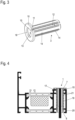
- vergrößerte Perspektivansicht auf eine Ankerhülse als eines der vorgenannten Bauteile; und
- Fig. 4
- Schnittansicht auf das erfindungsgemäße Profil.
-
Fig. 1-4 zeigen die Bauteile eines erfindungsgemäßen Profils 1 mit integriertem Schaltelement 4 mit einer Längsachse A. Dieses Schaltelement 4 ist vorzugsweise als sogenannter Reedkontakt ausgebildet. Durch den Reedkontakt sind u.a. Einbruchssicherungen, Öffnungssicherungen und eine Überwachung des Öffnungszustands im Rahmen eines Gebäudemanagements realisierbar. - Das Profil weist einen Profilkorpus 2 mit einer Bohrung 21 zur Aufnahme einer Anordnung aus Schaltelement 4 und einer Ankerhülse 3 in den Profilkorpus 2 und eine Öffnung 17 zum Zugang in die Bohrung 21 auf. Die Ankerhülse 3 weist eine Längsachse B auf, welche im montierten Zustand koaxial zur Längsachse A des Schaltelements 4 angeordnet ist.
- Das Schaltelement 4 weist einen stabförmigen Korpus 6 mit einer Außenmantelfläche auf. Dies kann vorzugsweise eine Zylindermantelfläche sein, aber auch eine Quadermantelfläche oder Prismenmantelfläche oder dergleichen.
- Vorzugsweise endständig weist das Schaltelement 4 einen Linearanschlag 7 zur Begrenzung der Linearbewegung des Schaltelements 4 entlang ihrer Längsachse bei ihrer Relativbewegung gegenüber der Ankerhülse 3 beim Einführen des Schaltelements in eine Hülsenöffnung 16.
- Die Ankerhülse 3 weist einen Hülsenkörper 19, vorzugsweise in zylindrischer Ausbildung, und demgegenüber radial-hervorstehende Rippen 14 zur Verbesserung des Kraft- und/oder Reibschlusses zwischen dem Profilmaterial und der Ankerhülse. Bekannterweise vergrößern derartige Rippen bei Dübeln und dergleichen die Radialkräfte auf das anliegende Material, hier das Profilmaterial.
- Die Ankerhülse 3 ist als Spreizhülse ausgebildet mit zwei in Längsrichtung verlaufenden Schlitzen 12 und 13. Eine der Schlitze 12 erstreckt sich durchgehend über die gesamte Länge der Ankerhülse, so dass die Hülse bereichsweise offen ist und dadurch ein Kabel 5 des Schaltelements durch den Schlitz 12 in den Hülseninnenraum geführt werden kann.
- Weiter weist die Ankerhülse einen vorzugsweise endständigen Linearanschlag 10 am Hülsenkörper 19 zum Anschlag mit der Öffnung 17 der Bohrung 21 auf. Der Linearanschlag 10 kann als ringscheibenförmiges Kopfsegment ausgebildet sein, welches radial gegenüber dem Hülsenkörper 19 hervorsteht.
- Der besagte Schlitz 12 verläuft als radiales Segment 11 insbesondere auch durch den Linearanschlag 10. Der zweite Schlitz 13 verläuft lediglich durch den Hülsenkörper 19 und erstreckt sich vorzugsweise über mehr als 80%, vorzugsweise zwischen 81-97%, der Länge des besagten Hülsenkörpers. Die lange Spreizzone der Ankerhülse 3 wirkt einer geringen Druckfestigkeit entgegen.
- Der Hülsenkörper 19 definiert einen geringeren Innendurchmesser als die endständige Hülsenöffnung 16, so dass sich daraus eine gestufte Öffnungsgeometrie mit einer Anschlagkante 15 ergibt, welche zugleich eine endständige Stirnfläche des Hülsenkörpers 19 ist. Schließlich weist die Ankerhülse 3 an der endständig dem Linearanschlag 10 gegenüberliegenden Seite eine Innenführungskante 20 auf, welche eine zusätzliche Führung und ggf. zusätzliche kraftschlüssige Festlegung zwischen der Ankerhülse 3 und dem Schaltelement erlaubt.
- Im montierten Zustand liegt der Linearanschlag 7 auf der Anschlagkante 15 auf, so dass eine Blockierung der Linearbewegung des Schaltelements 4 gegenüber der Ankerhülse 3 in eine erste Richtung erreicht wird. Dies ist insbesondere in
Fig. 4 erkennbar. - Weiter weist das Schaltelement 4, ebenfalls vorzugsweise endständig, Haltemittel 8, insbesondere Rastmittel auf, welche mit einer korrespondierenden Ausnehmung oder Kante der Ankerhülse durch Klemmschluss oder bevorzugt durch Formschluss verbunden sind. Dadurch wird eine Blockierung der Linearbewegung des Schaltelements 4 gegenüber der Ankerhülse 3 in eine zweite Richtung erreicht und das Schaltelement 4 liegt linear fixiert, vorzugsweise lösbar fixiert, in der Ankerhülse 3 ein. Das Haltemittel 8 ist insbesondere als Rastring ausgebildet mit einer umlaufenden Randnase. Der Rastring 8 ist seinerseits durch einen Schlitz 9 oder mehrere Schlitze in Längsrichtung zur Längsachse A zur besseren Verformbarkeit des Rastrings in radialer Richtung unterbrochen. Der Rastring 8 ist gegenüber dem Korpus 6 vorzugsweise zurückgesetzt und ebenfalls vorzugsweise endständig am Korpus 6 angeordnet. Weiterhin kann der Rastring 8 mit der Innenführungskante 20 der Ankerhülse 3 verrasten oder verklemmen.
- Wie schon zuvor erläutert geht ein vergleichsweise langes Kontaktkabel 5 vom Schaltelement 4 weg.
- Zur Montage wird in einem ersten Schritt 100 das Schaltelement 4 samt Kabel 5 durch die Bohrung 21 gefädelt. Hierin liegt bereits ein wesentlicher Unterschied zum Stand der Technik, in welchem bisher nur das rückseitige Kabel 5 durch die Bohrung 21 gefädelt wurde und der Reedkontakt bis zum Anschlag in der Bohrung 21 positioniert wurden. Dabei ist die radiale Dimensionierung des Schaltelements 4 kleiner als der Öffnungsquerschnitt der Bohrung.
- Sodann folgt in einem zweiten Schritt 200 das Durchführen des Kabels 5 aus senkrechter Richtung durch den Schlitz 12. Dieser kann ggf. geweitet werden. Hierfür besteht die Ankerhülse 3 aus einem spreizbaren Kunststoffmaterial, wie es z.B. bei handelsüblichen Spreizdübeln genutzt wird. Besonders bevorzugt ist hierbei ein Polyamid, insbesondere Nylon.
- Wie aus den Figuren erkennbar, ist das Haltemittel in Schritt 200 aus senkrechter Richtung zur Längsrichtung des Kabels 5 montierbar ausgebildet.
- Sodann wird die Ankerhülse 3 über das Schaltelement 4 gestülpt oder aber das Schaltelement 4 wird in die Ankerhülse 3 gesteckt. Die Ankerhülse weist bereichsweise eine breitere radiale Dimensionierung, insbesondere im Bereich des Linearanschlags 10, auf als der Öffnungsdurchmesser 17 der Bohrung 21. Somit schlägt die Anordnung aus Ankerhülse 3 und Schaltelement 4 am Profilkorpus 2 an.
- Schließlich wird die Anordnung in die Bohrung hineingesteckt. Die Anordnung wird durch die Rippen 14 und den Linearanschlag 10 in Position gehalten. Auf den Linearanschlag 10 ist sodann eine Abdeckkappe 18 optional aufsetzbar.
- Diese Form der Montage vermindert den Montageaufwand des Durchfädelns mehrerer Meter an Kabel 5 durch entgegengesetztes Durchstecken und anschließendes Befestigen des Schaltelements 4. Die Montage kann in kürzester Zeit ohne weitere Hilfsmittel auch vor Ort, also am Ort der Fenstermontage, durchgeführt werden.
-
- 1.
- Profil
- 2.
- Profilkorpus
- 3.
- Ankerhülse
- 4.
- Schaltelement
- 5.
- Kontaktkabel
- 6.
- Korpus (Schaltelement)
- 7.
- Linearanschlag (Schaltelement)
- 8.
- Rastring
- 9.
- Schlitz
- 10.
- Linearanschlag
- 11.
- Radiales Segment
- 12.
- Schlitz
- 13.
- Schlitz
- 14.
- Rippen
- 15.
- Anschlagkante
- 16.
- Hülsenöffnung
- 17.
- Öffnung
- 18.
- Abdeckkappe
- 19.
- Hülsenkörper
- 20.
- Innenführungskante
- 21.
- Bohrung
- 100
- erster Schritt (Durchfädeln)
- 200
- zweiter Schritt (Hülse ums Kabel)
- 300
- dritter Schritt (Einziehen)
- A
- Längsachse (Schaltelement)
- B
- Längsachse (Ankerhülse)
Claims (15)
- Profil (1) für Türen, Fenster, Blendrahmen oder Fassadenkonstruktionen mit einem Profilkorpus (2) umfassend eine Öffnung (17) und eine darin eingesetzte Anordnung aus einem Schaltelement (4) einer Schaltung und einem separaten Haltemittel mit einem Linearanschlag (10) zur Begrenzung der Linearbewegung der Anordnung innerhalb der Öffnung (17) des Profilkorpus (2), dadurch gekennzeichnet, dass das Schaltelement (4) ein endständiges Kabel (5) aufweist und dass das Haltemittel aus senkrechter Richtung zur Längsrichtung des Kabels (5) montierbar ausgebildet ist und
dass das Haltemittel, insbesondere die Ankerhülse (3), einen Schlitz (12) aufweist, welcher sich über die gesamte Länge des Haltemittels erstreckt. - Profil (1) nach Anspruch 1, dadurch gekennzeichnet, dass das separate Haltemittel als Ankerhülse (3) ausgebildet ist, wobei die Ankerhülse (3) einen Hülsenkörper (19), vorzugsweise in zylindrischer Ausgestaltung, und den Linearanschlag (10), vorzugsweise endständig zum Hülsenkörper (19), aufweist.
- Profil (1) nach Anspruch 1 oder 2, dadurch gekennzeichnet, dass der Linearanschlag (10) als Ringscheibe ausgebildet ist.
- Profil (1) nach einem der vorhergehenden Ansprüche, dadurch gekennzeichnet, dass das Schaltelement (4) als ein Reedkontakt ausgebildet ist.
- Profil (1) nach einem der vorhergehenden Ansprüche, dadurch gekennzeichnet, dass die Ankerhülse (3) form- oder kraftschlüssig mit dem Schaltelement (4) zu der Anordnung verbunden ist.
- Profil (1) nach einem der vorhergehenden Ansprüche, dadurch gekennzeichnet, dass das Haltemittel, insbesondere die Ankerhülse (3), als Spreizdübel bzw. Spreizhülse ausgebildet ist
- Profil (1) nach einem der vorhergehenden Ansprüche, dadurch gekennzeichnet, dass das Haltemittel, insbesondere die Ankerhülse (3), mit zumindest einem zweiten nicht-durchgehenden Schlitz (13) ausgebildet ist.
- Profil (1) nach einem der vorhergehenden Ansprüche, dadurch gekennzeichnet, dass sich der zweite Schlitz (13) über zumindest 80% des Hülsenkörpers (19) erstreckt.
- Profil (1) nach einem der vorhergehenden Ansprüche, dadurch gekennzeichnet, dass der maximale Durchmesser des Schaltelements (4) kleiner als Durchmesser eine Bohrung (21) oder die der Bohrung (21) zugeordneten Öffnung (17) im Profilkorpus (2), in welcher die Anordnung aus Haltemittel und Schaltelement (4) angeordnet ist.
- Profil (1) nach einem der vorhergehenden Ansprüche, dadurch gekennzeichnet, dass das Schaltelement (4) einen Linearanschlag (7) aufweist, zur Begrenzung der Linearbewegung des Schaltelements (4) gegenüber dem Haltemittel, insbesondere der Ankerhülse (3).
- Profil (1) nach einem der vorhergehenden Ansprüche, dadurch gekennzeichnet, dass das Schaltelement (4) ein endständiges Rastmittel, vorzugsweise einen Rastring (7), besonders bevorzugt einen Rastring (7) mit zumindest einem die Ringkontur unterbrechenden Schlitz (9), zur Begrenzung der Linearbewegung des Schaltelements (4) gegenüber dem Haltemittel aufweist.
- Profil (1) nach einem der vorhergehenden Ansprüche, dadurch gekennzeichnet, dass das Schaltelement (4) innerhalb des Haltemittels, vorzugsweise der Ankerhülse (3), durch das Rastmittel, insbesondere den Rastring (9) und den Linearanschlag (7) festgelegt, vorzugsweise lösbar festgelegt, ist.
- Profil (1) nach einem der vorhergehenden Ansprüche, dadurch gekennzeichnet, dass das Haltemittel, insbesondere die Ankerhülse (3), radiale Rippen (14) aufweist, welche radial gegenüber dem Hülsenkörper (19) hervorstehen.
- Profil (1) nach einem der vorhergehenden Ansprüche, dadurch gekennzeichnet, dass der Linearanschlag (10) der Ankerhülse (3) mit dem Linearanschlag (7) des Schaltelements (4) bündig abschließt, so dass sich eine gemeinsame Stirnfläche der Anordnung aus Ankerhülse (3) und Schaltelement (4) ausbildet.
- Profil (1) nach einem der vorhergehenden Ansprüche, dadurch gekennzeichnet, dass die Anordnung eine separate Abdeckkappe aufweist, welche vorzugsweise über der Stirnfläche angeordnet ist.
Applications Claiming Priority (1)
| Application Number | Priority Date | Filing Date | Title |
|---|---|---|---|
| DE202022107136.5U DE202022107136U1 (de) | 2022-12-21 | 2022-12-21 | Profil mit integriertem Schaltelement einer Schaltung |
Publications (2)
| Publication Number | Publication Date |
|---|---|
| EP4394157A1 true EP4394157A1 (de) | 2024-07-03 |
| EP4394157B1 EP4394157B1 (de) | 2025-06-11 |
Family
ID=85132637
Family Applications (1)
| Application Number | Title | Priority Date | Filing Date |
|---|---|---|---|
| EP23215756.0A Active EP4394157B1 (de) | 2022-12-21 | 2023-12-12 | Profil mit integriertem schaltelement einer schaltung |
Country Status (9)
| Country | Link |
|---|---|
| EP (1) | EP4394157B1 (de) |
| DE (1) | DE202022107136U1 (de) |
| DK (1) | DK4394157T3 (de) |
| ES (1) | ES3036857T3 (de) |
| FI (1) | FI4394157T3 (de) |
| HU (1) | HUE072665T2 (de) |
| LT (1) | LT4394157T (de) |
| PL (1) | PL4394157T3 (de) |
| PT (1) | PT4394157T (de) |
Citations (4)
| Publication number | Priority date | Publication date | Assignee | Title |
|---|---|---|---|---|
| DE202005011168U1 (de) * | 2005-07-15 | 2005-11-03 | Elram Wintergartentechnik Gmbh | Vorrichtung zum Befestigen von Beschlägen |
| DE102007032504A1 (de) | 2007-07-12 | 2009-01-22 | Link Gmbh | Sensoreinrichtung zur berührungsfreien Identitäts- oder Positionsermittlung |
| DE102009057256A1 (de) * | 2009-12-08 | 2011-06-09 | Link Gmbh | Sensoreinheit sowie Gebäudeüberwachungssystem mit derartigen Sensoreinheiten |
| DE102015113167A1 (de) * | 2015-08-10 | 2017-03-09 | Link Gmbh | Sensoreinheit sowie Gebäudeüberwachungs- und/oder Steuerungssystem mit derartigen Sensoreinheiten |
-
2022
- 2022-12-21 DE DE202022107136.5U patent/DE202022107136U1/de active Active
-
2023
- 2023-12-12 EP EP23215756.0A patent/EP4394157B1/de active Active
- 2023-12-12 FI FIEP23215756.0T patent/FI4394157T3/fi active
- 2023-12-12 HU HUE23215756A patent/HUE072665T2/hu unknown
- 2023-12-12 DK DK23215756.0T patent/DK4394157T3/da active
- 2023-12-12 PT PT232157560T patent/PT4394157T/pt unknown
- 2023-12-12 PL PL23215756.0T patent/PL4394157T3/pl unknown
- 2023-12-12 LT LTEP23215756.0T patent/LT4394157T/lt unknown
- 2023-12-12 ES ES23215756T patent/ES3036857T3/es active Active
Patent Citations (4)
| Publication number | Priority date | Publication date | Assignee | Title |
|---|---|---|---|---|
| DE202005011168U1 (de) * | 2005-07-15 | 2005-11-03 | Elram Wintergartentechnik Gmbh | Vorrichtung zum Befestigen von Beschlägen |
| DE102007032504A1 (de) | 2007-07-12 | 2009-01-22 | Link Gmbh | Sensoreinrichtung zur berührungsfreien Identitäts- oder Positionsermittlung |
| DE102009057256A1 (de) * | 2009-12-08 | 2011-06-09 | Link Gmbh | Sensoreinheit sowie Gebäudeüberwachungssystem mit derartigen Sensoreinheiten |
| DE102015113167A1 (de) * | 2015-08-10 | 2017-03-09 | Link Gmbh | Sensoreinheit sowie Gebäudeüberwachungs- und/oder Steuerungssystem mit derartigen Sensoreinheiten |
Also Published As
| Publication number | Publication date |
|---|---|
| PL4394157T3 (pl) | 2025-10-06 |
| PT4394157T (pt) | 2025-09-16 |
| EP4394157B1 (de) | 2025-06-11 |
| DE202022107136U1 (de) | 2023-01-18 |
| ES3036857T3 (en) | 2025-09-24 |
| FI4394157T3 (fi) | 2025-07-28 |
| HUE072665T2 (hu) | 2025-12-28 |
| LT4394157T (lt) | 2025-08-11 |
| DK4394157T3 (da) | 2025-08-18 |
Similar Documents
| Publication | Publication Date | Title |
|---|---|---|
| EP0233525B1 (de) | Vorrichtung zum lösbaren Verbinden zweier Profilstäbe | |
| DE3615488C2 (de) | ||
| WO2001036903A1 (de) | Messseil-wegsensor | |
| WO2000036311A1 (de) | Verbindungseinrichtung zum anschluss eines ersten werkstückes an ein zweites werkstück | |
| EP0019782A2 (de) | Metallhülsendübel | |
| EP4394157B1 (de) | Profil mit integriertem schaltelement einer schaltung | |
| DE202015104250U1 (de) | Pfosten-Riegel-Verbindung | |
| DE69030328T2 (de) | Haltevorrichtung für kolbenpositionsdetektor | |
| EP2405095A2 (de) | Türdichtung mit Befestigungselement | |
| EP3540160A1 (de) | Befestigungsanordnung zum befestigen eines türbandes an einem hohlkammer-profil | |
| EP1321681B1 (de) | Vorrichtung zum Halten eines Gegenstandes an einem Objekt sowie Verfahren zu dessen Befestigung an dem Objekt | |
| DE19522044A1 (de) | Eck- oder T-Verbindung an Rahmen oder Gestellen | |
| AT522794A4 (de) | Adapter zur Halterung von Fassadenelementen | |
| EP2881596B1 (de) | Montagekeil | |
| EP0592854A1 (de) | Lösbare Türdrückerverbindung | |
| DE19925859B4 (de) | Montagehilfe für eine Kraftfahrzeugtürkonstruktion | |
| EP4074989B1 (de) | Befestiger für eine schraubbefestigung an einer montageschiene und befestigungsanordnung mit einem solchen befestiger | |
| DE102020103627A1 (de) | Federstiftstossverbinder | |
| EP3675300A1 (de) | Adapter zur positionierung und befestigung eines installationsgehäuses | |
| DE10112842A1 (de) | Oberflächen-Entwässerungs-Anordnung | |
| DE102004034144A1 (de) | Mitnehmer zur Befestigung einer Fensterscheibe eines Kraftfahrzeuges an einer Führungseinrichtung eines Fensterhebers | |
| DE102005000195A1 (de) | Gleitstück für einen Beschlag | |
| EP2775083A2 (de) | Vorrichtung und Verfahren zur Befestigung eines Baukörpers in einer von einer Auflagefläche begrenzten Öffnung | |
| EP3546767B1 (de) | Verbinder für profile eines baukastensystems und baukastensystem | |
| EP0952294B1 (de) | Befestigungsanordnung für Fensterrahmen |
Legal Events
| Date | Code | Title | Description |
|---|---|---|---|
| PUAI | Public reference made under article 153(3) epc to a published international application that has entered the european phase |
Free format text: ORIGINAL CODE: 0009012 |
|
| STAA | Information on the status of an ep patent application or granted ep patent |
Free format text: STATUS: THE APPLICATION HAS BEEN PUBLISHED |
|
| AK | Designated contracting states |
Kind code of ref document: A1 Designated state(s): AL AT BE BG CH CY CZ DE DK EE ES FI FR GB GR HR HU IE IS IT LI LT LU LV MC ME MK MT NL NO PL PT RO RS SE SI SK SM TR |
|
| STAA | Information on the status of an ep patent application or granted ep patent |
Free format text: STATUS: REQUEST FOR EXAMINATION WAS MADE |
|
| 17P | Request for examination filed |
Effective date: 20241217 |
|
| GRAP | Despatch of communication of intention to grant a patent |
Free format text: ORIGINAL CODE: EPIDOSNIGR1 |
|
| STAA | Information on the status of an ep patent application or granted ep patent |
Free format text: STATUS: GRANT OF PATENT IS INTENDED |
|
| RIC1 | Information provided on ipc code assigned before grant |
Ipc: E06B 1/52 20060101AFI20250108BHEP |
|
| INTG | Intention to grant announced |
Effective date: 20250212 |
|
| GRAS | Grant fee paid |
Free format text: ORIGINAL CODE: EPIDOSNIGR3 |
|
| GRAA | (expected) grant |
Free format text: ORIGINAL CODE: 0009210 |
|
| STAA | Information on the status of an ep patent application or granted ep patent |
Free format text: STATUS: THE PATENT HAS BEEN GRANTED |
|
| P01 | Opt-out of the competence of the unified patent court (upc) registered |
Free format text: CASE NUMBER: APP_19929/2025 Effective date: 20250425 |
|
| AK | Designated contracting states |
Kind code of ref document: B1 Designated state(s): AL AT BE BG CH CY CZ DE DK EE ES FI FR GB GR HR HU IE IS IT LI LT LU LV MC ME MK MT NL NO PL PT RO RS SE SI SK SM TR |
|
| REG | Reference to a national code |
Ref country code: GB Ref legal event code: FG4D Free format text: NOT ENGLISH |
|
| REG | Reference to a national code |
Ref country code: CH Ref legal event code: EP |
|
| REG | Reference to a national code |
Ref country code: IE Ref legal event code: FG4D Free format text: LANGUAGE OF EP DOCUMENT: GERMAN |
|
| REG | Reference to a national code |
Ref country code: DE Ref legal event code: R096 Ref document number: 502023001141 Country of ref document: DE |
|
| REG | Reference to a national code |
Ref country code: FI Ref legal event code: FGE Ref country code: NL Ref legal event code: FP |
|
| REG | Reference to a national code |
Ref country code: DK Ref legal event code: T3 Effective date: 20250807 |
|
| REG | Reference to a national code |
Ref country code: SE Ref legal event code: TRGR |
|
| REG | Reference to a national code |
Ref country code: SK Ref legal event code: T3 Ref document number: E 46702 Country of ref document: SK |
|
| REG | Reference to a national code |
Ref country code: PT Ref legal event code: SC4A Ref document number: 4394157 Country of ref document: PT Date of ref document: 20250916 Kind code of ref document: T Free format text: AVAILABILITY OF NATIONAL TRANSLATION Effective date: 20250910 |
|
| REG | Reference to a national code |
Ref country code: ES Ref legal event code: FG2A Ref document number: 3036857 Country of ref document: ES Kind code of ref document: T3 Effective date: 20250924 |
|
| REG | Reference to a national code |
Ref country code: EE Ref legal event code: FG4A Ref document number: E025253 Country of ref document: EE Effective date: 20250728 |
|
| PG25 | Lapsed in a contracting state [announced via postgrant information from national office to epo] |
Ref country code: BG Free format text: LAPSE BECAUSE OF FAILURE TO SUBMIT A TRANSLATION OF THE DESCRIPTION OR TO PAY THE FEE WITHIN THE PRESCRIBED TIME-LIMIT Effective date: 20250611 |
|
| PG25 | Lapsed in a contracting state [announced via postgrant information from national office to epo] |
Ref country code: HR Free format text: LAPSE BECAUSE OF FAILURE TO SUBMIT A TRANSLATION OF THE DESCRIPTION OR TO PAY THE FEE WITHIN THE PRESCRIBED TIME-LIMIT Effective date: 20250611 |
|
| PG25 | Lapsed in a contracting state [announced via postgrant information from national office to epo] |
Ref country code: RS Free format text: LAPSE BECAUSE OF FAILURE TO SUBMIT A TRANSLATION OF THE DESCRIPTION OR TO PAY THE FEE WITHIN THE PRESCRIBED TIME-LIMIT Effective date: 20250911 |
|
| REG | Reference to a national code |
Ref country code: GR Ref legal event code: EP Ref document number: 20250401656 Country of ref document: GR Effective date: 20251009 |
|
| PGFP | Annual fee paid to national office [announced via postgrant information from national office to epo] |
Ref country code: PT Payment date: 20251205 Year of fee payment: 3 |
|
| REG | Reference to a national code |
Ref country code: HU Ref legal event code: AG4A Ref document number: E072665 Country of ref document: HU |
|
| PG25 | Lapsed in a contracting state [announced via postgrant information from national office to epo] |
Ref country code: IS Free format text: LAPSE BECAUSE OF FAILURE TO SUBMIT A TRANSLATION OF THE DESCRIPTION OR TO PAY THE FEE WITHIN THE PRESCRIBED TIME-LIMIT Effective date: 20251011 |
|
| PGFP | Annual fee paid to national office [announced via postgrant information from national office to epo] |
Ref country code: DE Payment date: 20251020 Year of fee payment: 3 |
|
| PGFP | Annual fee paid to national office [announced via postgrant information from national office to epo] |
Ref country code: NO Payment date: 20251104 Year of fee payment: 3 |
|
| PG25 | Lapsed in a contracting state [announced via postgrant information from national office to epo] |
Ref country code: SM Free format text: LAPSE BECAUSE OF FAILURE TO SUBMIT A TRANSLATION OF THE DESCRIPTION OR TO PAY THE FEE WITHIN THE PRESCRIBED TIME-LIMIT Effective date: 20250611 |
|
| PGFP | Annual fee paid to national office [announced via postgrant information from national office to epo] |
Ref country code: AT Payment date: 20260113 Year of fee payment: 3 |
|
| PGFP | Annual fee paid to national office [announced via postgrant information from national office to epo] |
Ref country code: FI Payment date: 20251216 Year of fee payment: 3 Ref country code: DK Payment date: 20251031 Year of fee payment: 3 |
|
| PGFP | Annual fee paid to national office [announced via postgrant information from national office to epo] |
Ref country code: FR Payment date: 20251203 Year of fee payment: 3 |
|
| PGFP | Annual fee paid to national office [announced via postgrant information from national office to epo] |
Ref country code: TR Payment date: 20251208 Year of fee payment: 3 Ref country code: GR Payment date: 20251215 Year of fee payment: 3 Ref country code: BE Payment date: 20251107 Year of fee payment: 3 |
|
| PGFP | Annual fee paid to national office [announced via postgrant information from national office to epo] |
Ref country code: CZ Payment date: 20251205 Year of fee payment: 3 |
|
| PGFP | Annual fee paid to national office [announced via postgrant information from national office to epo] |
Ref country code: PL Payment date: 20251017 Year of fee payment: 3 |
|
| PGFP | Annual fee paid to national office [announced via postgrant information from national office to epo] |
Ref country code: EE Payment date: 20251220 Year of fee payment: 3 |
|
| REG | Reference to a national code |
Ref country code: DE Ref legal event code: R097 Ref document number: 502023001141 Country of ref document: DE |
|
| PGFP | Annual fee paid to national office [announced via postgrant information from national office to epo] |
Ref country code: ES Payment date: 20260119 Year of fee payment: 3 |
|
| PGFP | Annual fee paid to national office [announced via postgrant information from national office to epo] |
Ref country code: IT Payment date: 20251231 Year of fee payment: 3 |
|
| PLBE | No opposition filed within time limit |
Free format text: ORIGINAL CODE: 0009261 |
|
| STAA | Information on the status of an ep patent application or granted ep patent |
Free format text: STATUS: NO OPPOSITION FILED WITHIN TIME LIMIT |
|
| REG | Reference to a national code |
Ref country code: CH Ref legal event code: L10 Free format text: ST27 STATUS EVENT CODE: U-0-0-L10-L00 (AS PROVIDED BY THE NATIONAL OFFICE) Effective date: 20260423 |