EP4394130A2 - Unterwasserfundament - Google Patents
Unterwasserfundament Download PDFInfo
- Publication number
- EP4394130A2 EP4394130A2 EP24174201.4A EP24174201A EP4394130A2 EP 4394130 A2 EP4394130 A2 EP 4394130A2 EP 24174201 A EP24174201 A EP 24174201A EP 4394130 A2 EP4394130 A2 EP 4394130A2
- Authority
- EP
- European Patent Office
- Prior art keywords
- pipe portion
- subsea
- lower pipe
- foundation
- pull
- Prior art date
- Legal status (The legal status is an assumption and is not a legal conclusion. Google has not performed a legal analysis and makes no representation as to the accuracy of the status listed.)
- Pending
Links
Images



Classifications
-
- E—FIXED CONSTRUCTIONS
- E02—HYDRAULIC ENGINEERING; FOUNDATIONS; SOIL SHIFTING
- E02D—FOUNDATIONS; EXCAVATIONS; EMBANKMENTS; UNDERGROUND OR UNDERWATER STRUCTURES
- E02D15/00—Handling building or like materials for hydraulic engineering or foundations
- E02D15/08—Sinking workpieces into water or soil inasmuch as not provided for elsewhere
-
- E—FIXED CONSTRUCTIONS
- E02—HYDRAULIC ENGINEERING; FOUNDATIONS; SOIL SHIFTING
- E02D—FOUNDATIONS; EXCAVATIONS; EMBANKMENTS; UNDERGROUND OR UNDERWATER STRUCTURES
- E02D23/00—Caissons; Construction or placing of caissons
- E02D23/08—Lowering or sinking caissons
-
- E—FIXED CONSTRUCTIONS
- E02—HYDRAULIC ENGINEERING; FOUNDATIONS; SOIL SHIFTING
- E02D—FOUNDATIONS; EXCAVATIONS; EMBANKMENTS; UNDERGROUND OR UNDERWATER STRUCTURES
- E02D27/00—Foundations as substructures
- E02D27/32—Foundations for special purposes
- E02D27/52—Submerged foundations, i.e. submerged in open water
-
- E—FIXED CONSTRUCTIONS
- E02—HYDRAULIC ENGINEERING; FOUNDATIONS; SOIL SHIFTING
- E02D—FOUNDATIONS; EXCAVATIONS; EMBANKMENTS; UNDERGROUND OR UNDERWATER STRUCTURES
- E02D27/00—Foundations as substructures
- E02D27/32—Foundations for special purposes
- E02D27/52—Submerged foundations, i.e. submerged in open water
- E02D27/525—Submerged foundations, i.e. submerged in open water using elements penetrating the underwater ground
-
- E—FIXED CONSTRUCTIONS
- E21—EARTH OR ROCK DRILLING; MINING
- E21B—EARTH OR ROCK DRILLING; OBTAINING OIL, GAS, WATER, SOLUBLE OR MELTABLE MATERIALS OR A SLURRY OF MINERALS FROM WELLS
- E21B33/00—Sealing or packing boreholes or wells
- E21B33/02—Surface sealing or packing
- E21B33/03—Well heads; Setting-up thereof
- E21B33/035—Well heads; Setting-up thereof specially adapted for underwater installations
-
- B—PERFORMING OPERATIONS; TRANSPORTING
- B63—SHIPS OR OTHER WATERBORNE VESSELS; RELATED EQUIPMENT
- B63B—SHIPS OR OTHER WATERBORNE VESSELS; EQUIPMENT FOR SHIPPING
- B63B21/00—Tying-up; Shifting, towing, or pushing equipment; Anchoring
- B63B21/24—Anchors
- B63B21/26—Anchors securing to bed
- B63B21/27—Anchors securing to bed by suction
-
- E—FIXED CONSTRUCTIONS
- E02—HYDRAULIC ENGINEERING; FOUNDATIONS; SOIL SHIFTING
- E02B—HYDRAULIC ENGINEERING
- E02B17/00—Artificial islands mounted on piles or like supports, e.g. platforms on raisable legs or offshore constructions; Construction methods therefor
- E02B2017/0056—Platforms with supporting legs
- E02B2017/0073—Details of sea bottom engaging footing
- E02B2017/0078—Suction piles, suction cans
-
- E—FIXED CONSTRUCTIONS
- E02—HYDRAULIC ENGINEERING; FOUNDATIONS; SOIL SHIFTING
- E02D—FOUNDATIONS; EXCAVATIONS; EMBANKMENTS; UNDERGROUND OR UNDERWATER STRUCTURES
- E02D2250/00—Production methods
- E02D2250/0053—Production methods using suction or vacuum techniques
-
- E—FIXED CONSTRUCTIONS
- E02—HYDRAULIC ENGINEERING; FOUNDATIONS; SOIL SHIFTING
- E02D—FOUNDATIONS; EXCAVATIONS; EMBANKMENTS; UNDERGROUND OR UNDERWATER STRUCTURES
- E02D2600/00—Miscellaneous
- E02D2600/20—Miscellaneous comprising details of connection between elements
-
- E—FIXED CONSTRUCTIONS
- E02—HYDRAULIC ENGINEERING; FOUNDATIONS; SOIL SHIFTING
- E02D—FOUNDATIONS; EXCAVATIONS; EMBANKMENTS; UNDERGROUND OR UNDERWATER STRUCTURES
- E02D27/00—Foundations as substructures
- E02D27/10—Deep foundations
- E02D27/18—Foundations formed by making use of caissons
-
- E—FIXED CONSTRUCTIONS
- E02—HYDRAULIC ENGINEERING; FOUNDATIONS; SOIL SHIFTING
- E02D—FOUNDATIONS; EXCAVATIONS; EMBANKMENTS; UNDERGROUND OR UNDERWATER STRUCTURES
- E02D7/00—Methods or apparatus for placing sheet pile bulkheads, piles, mouldpipes, or other moulds
- E02D7/20—Placing by pressure or pulling power
-
- E—FIXED CONSTRUCTIONS
- E21—EARTH OR ROCK DRILLING; MINING
- E21B—EARTH OR ROCK DRILLING; OBTAINING OIL, GAS, WATER, SOLUBLE OR MELTABLE MATERIALS OR A SLURRY OF MINERALS FROM WELLS
- E21B41/00—Equipment or details not covered by groups E21B15/00 - E21B40/00
- E21B41/10—Guide posts, e.g. releasable; Attaching guide lines to underwater guide bases
Definitions
- the invention relates to a subsea foundation system and a method of connecting a lower pipe portion to a subsea foundation.
- the subsea foundation further comprises an inner member in the form of a pipe. It has been found that it is beneficial for the subsea foundation to have a shorter pipe during transportation and before deployment subsea but a longer pipe before the subsea foundation is landed on the seabed.
- WO2017/179992 It is known from WO2017/179992 to provide a subsea foundation comprising a suction anchor with a two part inner member.
- the lower part of that member protrudes from the suction skirt of the suction anchor and is attached to the suction anchor at the installation site. This is achieved by first placing the lower part on the seabed, then deploying the suction anchor subsea, next connecting a pull-in line between the lower part and the machine anchor, and then connecting the lower part to the upper part subsea using a pull-in line through the centre of the inner member.
- the present invention provides a method of connecting a lower pipe portion to a subsea foundation, the method comprising: providing the subsea foundation, wherein the subsea foundation comprises an upper pipe portion connected to the subsea foundation, deploying the subsea foundation subsea; and connecting the lower pipe portion to the upper pipe portion.
- the upper pipe portion may not protrude beyond the bottom of the suction anchor.
- the subsea foundation may comprise a suction anchor and the upper pipe portion may be connected to the suction anchor.
- the present invention may provide a subsea foundation system for deployment subsea, wherein the subsea foundation system comprises: a subsea foundation, e.g. a subsea foundation comprising a suction anchor; an upper pipe portion connected to the subsea foundation, e.g. the suction anchor; and a lower pipe portion connected to the subsea foundation, e.g. the suction anchor, in a stowed position, wherein the subsea foundation system is arranged such that subsea the lower pipe portion can be released from the stowed position and connected to the upper pipe portion.
- a subsea foundation e.g. a subsea foundation comprising a suction anchor
- an upper pipe portion connected to the subsea foundation, e.g. the suction anchor
- a lower pipe portion connected to the subsea foundation, e.g. the suction anchor
- the present invention may provide a subsea foundation system for deployment subsea, wherein the subsea foundation comprises: a subsea foundation (e.g. comprising a suction anchor); an upper pipe portion connected to the subsea foundation, e.g. suction anchor; and a lower pipe portion connected to a pull-in arrangement, wherein the subsea foundation system is arranged such that subsea the lower pipe portion can be connected to the upper pipe portion using the pull-in arrangement.
- a subsea foundation e.g. comprising a suction anchor
- an upper pipe portion connected to the subsea foundation, e.g. suction anchor
- a lower pipe portion connected to a pull-in arrangement
- the present invention provides a method of connecting a lower pipe portion to a subsea foundation, the method comprising: providing the subsea foundation (optionally comprising a suction anchor) comprising an upper pipe portion connected to the subsea foundation, e.g. the suction anchor; providing a lower pipe portion and a pipe overlap section; and connecting the lower pipe portion to the upper pipe portion such that the pipe overlap section overlaps a portion of the upper pipe portion and/or the lower pipe portion.
- the suction anchor in a stowed position; deploying the subsea foundation subsea with the lower pipe portion in the stowed position and connected to the pull-in arrangement; releasing the lower pipe portion from the stowed position subsea; and connecting the lower pipe portion to the upper pipe portion using the pull in arrangement such that the pipe overlap section overlaps a portion of the upper pipe portion and/or the lower pipe portion.
- the lower pipe portion may be connected to the upper pipe portion when the subsea foundation, e.g. suction anchor, is subsea but before it reaches the seabed.
- the subsea foundation e.g. suction anchor
- the subsea foundation may be suspended above the seabed whilst the lower pipe portion is connected to the upper pipe portion.
- the lower pipe section When the lower pipe section is connected to the pull-in arrangement and the subsea foundation, e.g. the suction anchor, is ready for deployment, the lower pipe section may not (yet) be connected to the upper pipe portion.
- the pull-in lines may extend through the upper pipe portion.
- the pull-in lines may extend through the wall of the upper pipe portion.
- the pull-in lines may extend through the wall of the upper pipe portion at an elevation that is above the foundation, e.g. above the suction anchor, yet is below other components, such as a conductor housing (if present). The may mean that the pull-in lines do not have to pass through the suction volume if the foundation is a suction anchor.
- the pull-in arrangement e.g. the pull-in line(s)
- the pull-in arrangement may be positioned so that it can be operated whilst the subsea foundation is suspended by a lifting arrangement, e.g. lifting wires.
- the pull-in line(s) may be located so that they can be pulled through the subsea foundation whilst the foundation is suspended subsea.
- the second direction may be a downwards direction, e.g. into of the internal volume of the suction anchor and may cause the lower pipe portion to move away from the upper pipe portion.
- a pulling mechanism such as a crane, winch, ROV or buoyancy element etc., may be used to pull the pull-in line through the subsea foundation (e.g. in a direction towards the top of the suction anchor) so as to pull the lower pipe portion towards and then perhaps into connection with the upper pipe portion.
- the pull-in line(s) may be pulled through the subsea foundation, e.g. using a pull-in mechanism, to pull the lower pipe portion towards the upper pipe portion.
- the pull-in line may be pulled through the pull-in line conduit and/or the pull-in line grip.
- the pull-in line grip may act to prevent the pull-in line moving back in the opposite direction.
- the pull-in line grip may have a release mechanism. This may allow the pull-in line to be released when desired, e.g. during retrieval of the subsea foundation.
- the lower pipe portion may comprise and/or be connected to pull-in line connection point(s).
- pull-in line connection point for each pull-in line.
- the pull-in line connection wing(s) may extend radially outward from the lower pipe portion. This is so that the pull-in line(s) may be radially spaced from the lower pipe portion. This radial spacing may aid aligning the lower pipe portion with the upper pipe portion for connection.
- the pull-in line connection point(s) When the lower pipe portion is connected to the upper pipe portion, the pull-in line connection point(s) may be aligned with, e.g. underneath, a respective pull-in line grip. This is so that the pull-in line can extend directly upwards from the pull-in line connection point, through the pull-in line conduit to the pull-in line grip.
- the pipe overlap section (if present) may overlap the upper pipe portion and the lower pipe portion.
- the pipe overlap section may have an inner diameter that is equal to the outer diameter of the upper pipe portion and/or the lower pipe portion.
- the inner diameter of the lower pipe portion may the same as the inner diameter of the upper pipe portion.
- the outer diameter of the lower pipe portion may the same as the outer diameter of the upper pipe portion.
- the pipe overlap section may ensure that there is a connection between the upper and lower pipe portion in a lateral direction.
- the pipe overlap portion may allow the connection to withstand lateral forces.
- a simple end to end connection of the upper and lower pipe portions without an overlap section may be liable to disengage whilst the lower pipe portion is being sunk into the seabed, .e.g. if the lower pipe portion hits an obstruction, such as a rock, on one side.
- the pipe overlap section may be welded to the upper pipe portion or the lower pipe portion. This welding may be performed before the foundation is deployed subsea.
- the pipe overlap section may also overlap the pipe portion it is welded to.
- the pipe overlap section and lower pipe portion may together form a pipe extension.
- the method may comprising receiving the upper pipe portion and/or the lower pipe portion within the pipe overlap section.
- the upper pipe portion and/or the lower pipe portion may be received within the pipe overlap section until it abuts the other of the lower pipe portion and/or the upper pipe portion.
- the abutting of the lower pipe portion and the upper pipe portion may act as a stop to prevent the upper pipe portion or the lower pipe portion being received any further into the pipe overlap section.
- the pipe overlap section may be put into the stowed position with the lower pipe portion.
- the pull-in arrangement When the pipe overlap section is connected to the lower pipe portion, the pull-in arrangement may be connected to the lower pipe portion via the pipe overlap section.
- the pull-in arrangement e.g. pull-in lines and/or pull-in line connection wings, may be connected to the pipe overlap section.
- the pipe overlap section may be shaped, e.g. sufficiently short, such that when the upper pipe portion and lower pipe portion are connected, the pipe overlap section is not obstructed by other components of the foundation, such as stiffening plates (if present).
- the stiffening plates may be plates that, if the foundation comprises a suction anchor, radially extend between the outer suction skirt and the inner pipe of the suction anchor.
- the foundation may comprise a pipe connection guide for guiding the connection between the upper pipe portion and lower pipe portion.
- the pipe connection guide may be fixed (directly or indirectly, such as via the pipe overlap section) to (e.g. an end of) the upper pipe portion and/or the lower pipe portion.
- the pipe connection guide may be located at a top end of the pipe overlap section which receives the upper pipe portion.
- the pipe connection guide may comprise a guide funnel.
- the guide funnel may be circumferentially discontinuous. This is so that the guide funnel does not interfere with other components of the foundation, such as stiffening plates (if present).
- the guide funnel is circumferentially discontinuous, e.g. made up of obliquely angled guide pieces, parts of the foundation, e.g. stiffening plates, may be located between the discontinuous pieces, when the lower pipe portion is connected to the upper pipe portion.
- connection guide may thus comprise one or more obliquely angled guide pieces.
- connection guide may have a wider diameter at its entrance that may facilitate connecting the lower pipe portion to the upper pipe portion.
- connection guide may help guide the upper pipe portion or the lower pipe portion into the pipe overlap section.
- the upper and lower pipe portion may be fixed together with a snap ring (e.g. in an overlapping section).
- the upper and lower pipe portion may be fixed together using any sort of connection such as a threaded connection or a quick lock connection.
- the system may comprise an internal, releasable and reusable fixing tool.
- the tool may be arranged so that in use it can hold onto the lower section as it is pulled up and then snapped in place.
- the snap ring may be made to hold a certain weight. The snap ring may be released on retrieval of the foundation.
- the retrieval method may comprise disconnecting the pull-in arrangement from the subsea foundation. This may be achieved by releasing the pull-in line grip(s) and/or cutting the pull-in line(s) (e.g. with cutting pliers).
- the method may comprise forcing the foundation out of the seabed, e.g. by pumping fluid into the internal volume of the suction anchor to force the suction anchor out of the seabed, whilst leaving the lower pipe portion, and optionally the pipe overlap section, if present, behind.
- suction anchor, upper pipe portion, lower pipe portion and pipe overlap section (if present) together may form at least part of a subsea foundation system.
- the upper pipe portion and lower pipe portion when connected together may provide a pipe for a well, e.g. a conductor.
- the present invention may provide, a subsea well foundation, the foundation comprising: a suction anchor, the suction anchor comprising an inner pipe for a well and an outer suction skirt located around/about the inner pipe, wherein the inner pipe comprises the upper pipe portion and the lower pipe portion.
- the upper pipe may be connected to and/or extend outside of the foundation, e.g. outside of the suction skirt of the suction anchor. Even in this case the upper pipe may not protrude beyond the bottom of the foundation.
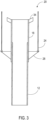
- the pipe overlap section 18 may be fixed, such as welded, to the lower pipe portion 12 which together may form a pipe extension 20 as shown in figure 3 .
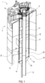
- a pipe connection guide 34 is made up of a number of obliquely angled guide pieces that forms a circumferentially discontinuous guide funnel.
- the subsea foundation 1 may be deployed subsea.
- the subsea foundation may be held via lifting wires (not shown) connected to pad eyes 38.
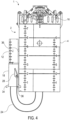
- the lower pipe portion 12 may then be connected to the upper pipe portion 12 by pulling in the pull-in lines through the conduits 26 and grips 30. This pull in may be performed by a winch for example. Once pulled through the suction anchor 2 by a desired amount, excess pull-in line above the grips 30 may be cut off.
Landscapes
- Engineering & Computer Science (AREA)
- Mining & Mineral Resources (AREA)
- Life Sciences & Earth Sciences (AREA)
- General Engineering & Computer Science (AREA)
- General Life Sciences & Earth Sciences (AREA)
- Structural Engineering (AREA)
- Paleontology (AREA)
- Civil Engineering (AREA)
- Geology (AREA)
- Physics & Mathematics (AREA)
- Environmental & Geological Engineering (AREA)
- Fluid Mechanics (AREA)
- Geochemistry & Mineralogy (AREA)
- Foundations (AREA)
- Piles And Underground Anchors (AREA)
Applications Claiming Priority (3)
| Application Number | Priority Date | Filing Date | Title |
|---|---|---|---|
| GB1912265.4A GB2587324B8 (en) | 2019-08-27 | 2019-08-27 | Subsea foundation |
| EP20855928.6A EP4018045A4 (de) | 2019-08-27 | 2020-08-27 | Unterwasserfundament und verfahren zur installation |
| PCT/NO2020/050217 WO2021040533A1 (en) | 2019-08-27 | 2020-08-27 | Subsea foundation and method of installing |
Related Parent Applications (1)
| Application Number | Title | Priority Date | Filing Date |
|---|---|---|---|
| EP20855928.6A Division EP4018045A4 (de) | 2019-08-27 | 2020-08-27 | Unterwasserfundament und verfahren zur installation |
Publications (2)
| Publication Number | Publication Date |
|---|---|
| EP4394130A2 true EP4394130A2 (de) | 2024-07-03 |
| EP4394130A3 EP4394130A3 (de) | 2024-09-11 |
Family
ID=68108918
Family Applications (3)
| Application Number | Title | Priority Date | Filing Date |
|---|---|---|---|
| EP24174201.4A Pending EP4394130A3 (de) | 2019-08-27 | 2020-08-27 | Unterwasserfundament |
| EP24174200.6A Pending EP4394129A3 (de) | 2019-08-27 | 2020-08-27 | Unterwasserfundament |
| EP20855928.6A Pending EP4018045A4 (de) | 2019-08-27 | 2020-08-27 | Unterwasserfundament und verfahren zur installation |
Family Applications After (2)
| Application Number | Title | Priority Date | Filing Date |
|---|---|---|---|
| EP24174200.6A Pending EP4394129A3 (de) | 2019-08-27 | 2020-08-27 | Unterwasserfundament |
| EP20855928.6A Pending EP4018045A4 (de) | 2019-08-27 | 2020-08-27 | Unterwasserfundament und verfahren zur installation |
Country Status (8)
| Country | Link |
|---|---|
| US (3) | US12116748B2 (de) |
| EP (3) | EP4394130A3 (de) |
| AU (1) | AU2020337731B2 (de) |
| BR (1) | BR112022003556A2 (de) |
| CA (1) | CA3152817A1 (de) |
| GB (1) | GB2587324B8 (de) |
| MX (1) | MX2022002383A (de) |
| WO (1) | WO2021040533A1 (de) |
Families Citing this family (2)
| Publication number | Priority date | Publication date | Assignee | Title |
|---|---|---|---|---|
| CN113212655B (zh) * | 2021-06-11 | 2022-04-15 | 西北工业大学 | 一种无人水下航行器海底驻留的吸力锚装置及其控制方法 |
| GB2639614A (en) * | 2024-03-19 | 2025-10-01 | Equinor Energy As | Pipe part for connecting to a subsea foundation |
Citations (1)
| Publication number | Priority date | Publication date | Assignee | Title |
|---|---|---|---|---|
| WO2017179992A1 (en) | 2016-04-11 | 2017-10-19 | Statoil Petroleum As | Subsea foundation |
Family Cites Families (9)
| Publication number | Priority date | Publication date | Assignee | Title |
|---|---|---|---|---|
| US2082773A (en) * | 1934-05-02 | 1937-06-08 | William G Adams | Method and apparatus for building subaqueous foundations |
| US4830541A (en) * | 1986-05-30 | 1989-05-16 | Shell Offshore Inc. | Suction-type ocean-floor wellhead |
| US6659182B1 (en) * | 2002-07-11 | 2003-12-09 | Halliburton Energy Services, Inc. | Retrievable suction embedment chamber assembly |
| GB0520891D0 (en) * | 2005-10-14 | 2005-11-23 | Tidal Generation Ltd | Foundation structure for water current energy system |
| NO20085187L (no) * | 2008-12-12 | 2010-06-14 | Sclantic Subsea As | Anordning ved sugefundament |
| KR101546484B1 (ko) * | 2013-10-29 | 2015-08-24 | (주)대우건설 | 원위치에서 수직 인발이 가능한 석션 파일 앵커 시공방법 |
| KR101559472B1 (ko) * | 2014-08-18 | 2015-10-13 | (주)동명기술공단종합건축사사무소 | 수중 지지구조물용 기초부 시공방법 |
| WO2017091085A1 (en) * | 2015-11-25 | 2017-06-01 | Neodrill As | System and method for foundation of wellheads |
| NO342444B1 (no) | 2015-11-25 | 2018-05-22 | Neodrill As | System for fundamentering av brønnhoder |
-
2019
- 2019-08-27 GB GB1912265.4A patent/GB2587324B8/en active Active
-
2020
- 2020-08-27 MX MX2022002383A patent/MX2022002383A/es unknown
- 2020-08-27 EP EP24174201.4A patent/EP4394130A3/de active Pending
- 2020-08-27 BR BR112022003556A patent/BR112022003556A2/pt unknown
- 2020-08-27 EP EP24174200.6A patent/EP4394129A3/de active Pending
- 2020-08-27 WO PCT/NO2020/050217 patent/WO2021040533A1/en not_active Ceased
- 2020-08-27 EP EP20855928.6A patent/EP4018045A4/de active Pending
- 2020-08-27 CA CA3152817A patent/CA3152817A1/en active Pending
- 2020-08-27 AU AU2020337731A patent/AU2020337731B2/en active Active
- 2020-08-27 US US17/639,775 patent/US12116748B2/en active Active
-
2024
- 2024-09-13 US US18/884,916 patent/US20250003172A1/en active Pending
- 2024-09-13 US US18/884,884 patent/US20250012035A1/en active Pending
Patent Citations (1)
| Publication number | Priority date | Publication date | Assignee | Title |
|---|---|---|---|---|
| WO2017179992A1 (en) | 2016-04-11 | 2017-10-19 | Statoil Petroleum As | Subsea foundation |
Also Published As
| Publication number | Publication date |
|---|---|
| GB2587324A8 (en) | 2024-07-31 |
| EP4018045A1 (de) | 2022-06-29 |
| MX2022002383A (es) | 2022-03-17 |
| US12116748B2 (en) | 2024-10-15 |
| EP4394129A3 (de) | 2024-09-11 |
| EP4394130A3 (de) | 2024-09-11 |
| US20250003172A1 (en) | 2025-01-02 |
| GB2587324B (en) | 2022-06-15 |
| US20220333334A1 (en) | 2022-10-20 |
| BR112022003556A2 (pt) | 2022-05-24 |
| EP4018045A4 (de) | 2023-09-13 |
| US20250012035A1 (en) | 2025-01-09 |
| AU2020337731A1 (en) | 2022-03-31 |
| EP4394129A2 (de) | 2024-07-03 |
| CA3152817A1 (en) | 2021-03-04 |
| GB201912265D0 (en) | 2019-10-09 |
| GB2587324A (en) | 2021-03-31 |
| AU2020337731B2 (en) | 2025-11-20 |
| WO2021040533A1 (en) | 2021-03-04 |
| GB2587324B8 (en) | 2024-07-31 |
Similar Documents
| Publication | Publication Date | Title |
|---|---|---|
| US20250003172A1 (en) | Subsea foundation | |
| US20240286713A1 (en) | Marine suction anchor | |
| US11506012B2 (en) | Subsea wellhead assembly | |
| US4403658A (en) | Multiline riser support and connection system and method for subsea wells | |
| US3967462A (en) | Method and apparatus for joining a subsea pipeline to an offshore platform riser | |
| US9347270B2 (en) | Pre-positioned capping device and diverter | |
| MX2007009849A (es) | Sistema y metodo para intervencion de pozos. | |
| AU2009334509B2 (en) | Rigless abandonment system | |
| NO347742B1 (en) | Offshore flexible line installation and removal | |
| AU2011215983B2 (en) | Rigless intervention | |
| CN103492660A (zh) | 海上流体输送系统和方法 | |
| EP3049579B1 (de) | Sauganker | |
| US8146668B2 (en) | Downhole tubular lifter and method of using the same | |
| US8678707B1 (en) | Well-head blowout containment system | |
| US11028663B1 (en) | Process and apparatus for installing a payload onto a subsea structure | |
| US10781670B1 (en) | Process for non-vertical installation and removal of a subsea structure | |
| US4776727A (en) | Quick release platform grouting valve system |
Legal Events
| Date | Code | Title | Description |
|---|---|---|---|
| PUAI | Public reference made under article 153(3) epc to a published international application that has entered the european phase |
Free format text: ORIGINAL CODE: 0009012 |
|
| STAA | Information on the status of an ep patent application or granted ep patent |
Free format text: STATUS: THE APPLICATION HAS BEEN PUBLISHED |
|
| AC | Divisional application: reference to earlier application |
Ref document number: 4018045 Country of ref document: EP Kind code of ref document: P |
|
| AK | Designated contracting states |
Kind code of ref document: A2 Designated state(s): AL AT BE BG CH CY CZ DE DK EE ES FI FR GB GR HR HU IE IS IT LI LT LU LV MC MK MT NL NO PL PT RO RS SE SI SK SM TR |
|
| REG | Reference to a national code |
Ref country code: DE Ref legal event code: R079 Free format text: PREVIOUS MAIN CLASS: E02B0017000000 Ipc: E02D0027520000 |
|
| PUAL | Search report despatched |
Free format text: ORIGINAL CODE: 0009013 |
|
| AK | Designated contracting states |
Kind code of ref document: A3 Designated state(s): AL AT BE BG CH CY CZ DE DK EE ES FI FR GB GR HR HU IE IS IT LI LT LU LV MC MK MT NL NO PL PT RO RS SE SI SK SM TR |
|
| RIC1 | Information provided on ipc code assigned before grant |
Ipc: E02B 17/00 20060101ALI20240802BHEP Ipc: E21B 41/10 20060101ALI20240802BHEP Ipc: E21B 33/035 20060101ALI20240802BHEP Ipc: B63B 21/27 20060101ALI20240802BHEP Ipc: E02D 7/20 20060101ALI20240802BHEP Ipc: E02D 27/18 20060101ALI20240802BHEP Ipc: E02D 15/08 20060101ALI20240802BHEP Ipc: E02D 23/08 20060101ALI20240802BHEP Ipc: E02D 27/52 20060101AFI20240802BHEP |
|
| STAA | Information on the status of an ep patent application or granted ep patent |
Free format text: STATUS: REQUEST FOR EXAMINATION WAS MADE |
|
| 17P | Request for examination filed |
Effective date: 20250226 |
|
| STAA | Information on the status of an ep patent application or granted ep patent |
Free format text: STATUS: EXAMINATION IS IN PROGRESS |
|
| 17Q | First examination report despatched |
Effective date: 20260225 |