EP4394102A1 - A household appliance comprising a cable holder - Google Patents
A household appliance comprising a cable holder Download PDFInfo
- Publication number
- EP4394102A1 EP4394102A1 EP23220164.0A EP23220164A EP4394102A1 EP 4394102 A1 EP4394102 A1 EP 4394102A1 EP 23220164 A EP23220164 A EP 23220164A EP 4394102 A1 EP4394102 A1 EP 4394102A1
- Authority
- EP
- European Patent Office
- Prior art keywords
- household appliance
- wing
- cable holder
- panel
- mounting hole
- Prior art date
- Legal status (The legal status is an assumption and is not a legal conclusion. Google has not performed a legal analysis and makes no representation as to the accuracy of the status listed.)
- Pending
Links
- 210000000078 claw Anatomy 0.000 claims description 9
- 238000005406 washing Methods 0.000 claims description 3
- 238000009434 installation Methods 0.000 description 2
- 238000010411 cooking Methods 0.000 description 1
- 230000000694 effects Effects 0.000 description 1
- 239000007788 liquid Substances 0.000 description 1
- 238000004519 manufacturing process Methods 0.000 description 1
- 239000000463 material Substances 0.000 description 1
- 238000000034 method Methods 0.000 description 1
Images


Classifications
-
- D—TEXTILES; PAPER
- D06—TREATMENT OF TEXTILES OR THE LIKE; LAUNDERING; FLEXIBLE MATERIALS NOT OTHERWISE PROVIDED FOR
- D06F—LAUNDERING, DRYING, IRONING, PRESSING OR FOLDING TEXTILE ARTICLES
- D06F34/00—Details of control systems for washing machines, washer-dryers or laundry dryers
- D06F34/04—Signal transfer or data transmission arrangements
-
- D—TEXTILES; PAPER
- D06—TREATMENT OF TEXTILES OR THE LIKE; LAUNDERING; FLEXIBLE MATERIALS NOT OTHERWISE PROVIDED FOR
- D06F—LAUNDERING, DRYING, IRONING, PRESSING OR FOLDING TEXTILE ARTICLES
- D06F39/00—Details of washing machines not specific to a single type of machines covered by groups D06F9/00 - D06F27/00
- D06F39/12—Casings; Tubs
Definitions
- the household appliance comprises the cable holder comprising a cable opening which is suitable for passing cables therethrough.
- the cables guided on the cable holder are held more easily and safely.
- the household appliance comprises the shutter having a movable second wing which can be shifted to a first position so as to cover, from inside the body, a mounting hole in the panel to which the cable holder is to be connected, and to a second position so as to open said mounting hole to enable the fixing mechanism to come out of the mounting hole, preferably by making a pivotal movement between 70° and 100°, if pushed by a fixing means.
- the second wing is shifted to the desired position only by making a pivotal movement.
- the household appliance (100) of the present invention further comprises the cable holder (1) having a movable shutter (2) which can be moved to a first position to cover a mounting hole (103) on the panel (102) to which the cable holder (1) is to be connected, and to a second position to open said mounting hole (103).
- the number of board holders (4) comprising the electronic components required for the operation of the system varies, and therefore the mounting holes (103) formed in the body (101) may also vary.
- the mounting hole (103) can be closed by means of the shutter (2) feature of the cable holder (1) attached to the panel (102) which is manufactured such that there are more mounting holes (103) than desired.
- the cable holder (1) comprises a cable opening (15) suitable for passing a cable bundle therethrough.
- the cable bundles pass therethrough, and said cables are enabled to be kept in the desired position in the body (101), guided and directed.
- the cable opening (15) is configured to be an opening suitable for passing a plurality of cables in the standard style.
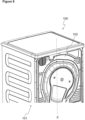
- FIG 9 shows an example of the household appliance (100) of the present invention, and the household appliance (100) of the present invention can be a laundry dryer or a washing machine.
- a household appliance (100) is realized, comprising a cable holder (1) which can be used in a plurality of models, wherein costs and labor are reduced.
Landscapes
- Engineering & Computer Science (AREA)
- Computer Networks & Wireless Communication (AREA)
- Textile Engineering (AREA)
- Installation Of Indoor Wiring (AREA)
Abstract
The present invention relates to a household appliance (100) comprising a body (101); a panel (102) which is disposed on an accessible exterior surface of the body (101); and a cable holder (1) which is suitable to be placed on the surface of the panel (102) facing the interior of the body (101) and which enables one or more cables to be guided and held thereon; wherein the cable holder (1) has a movable shutter (2) which can be moved to a first position to cover a mounting hole (103) on the panel (102) to which the cable holder (1) is to be connected, and to a second position to open said mounting hole (103).
Description
- The present invention relates to a household appliance comprising a cable holder with shutter feature.
- Electronic household appliances are manufactured with different structural and system characteristics depending on the customer demand. For example, in washing machines and laundry dryers, products are diversified depending on control system, loading capacity, number of programs, speed characteristics and similar features. The use of separate components for all types of features offers great diversity, but may also cause difficulties for the design, production, material supply and assembly processes. Accordingly, the number of the board holders used in some household appliances may vary. Therefore, the number of mounting holes formed in the body may vary.
- Leaving the hole formed for installation open without closing the same poses risks such as liquid reaching into the machine. In order to prevent such a possible leak from reaching the board groups, sponge cut in appropriate form is used in the state of the art. On the other hand, the use of sponge causes additional installation work and additional components costs.
- In the state of the European Patent Application No.
EP2107655 , a cable holder is disclosed, that is used in household appliances for attaching the cables. - The aim of the present invention is the realization of a household appliance having a cable holder which is suitable to be used in different types of household appliances and which closes the existing mounting hole if desired.
- The household appliance of the present invention comprises a body; a panel which is disposed on an accessible exterior surface of the body; and a cable holder which is suitable to be placed on the surface of the panel facing the interior of the body, which enables one or more cables to be guided and held thereon and which has a movable shutter that can be moved to a first position to cover a mounting hole on the panel to which said cable holder is to be connected, and to a second position to open said mounting hole. Thus, the extra labor and cost required to close the mounting hole is eliminated.
- The household appliance of the present invention comprises a fixing mechanism which enables the cable holder to be connected to the panel. Thus, the cable holder is firmly connected to the panel. By means of the fixing mechanism, it becomes possible to detach the cable holder.
- In an embodiment of the present invention, the fixing mechanism comprises a main body in the form of a truncated cone and two opposite support surfaces which expand outwards from said main body at an angle. Thus, the fixing mechanism first narrows down and passes through the hole formed on the panel, and after passing, expands such that the support surfaces return to the initial position, preventing the fixing mechanism from dislodging. In order to make said support surface flexible, there are cavities in the form of a cut-out formed so as to extend in the direction of the longitudinal axis of the fixing mechanism. Thus, a structure which can stretch during the assembly is obtained.
- In an embodiment of the present invention, the shutter comprises a fixed first wing which extends parallel to the panel to which the cable holder is to be connected and a second wing which is movably connected to said first wing. Thus, one of the wings is configured to be fixed and the other to be movable so as to enable the mounting hole to be opened/closed by one of the wings if desired.
- In an embodiment of the present invention, the shutter comprises an interconnection region between the first wing and the second wing. By means of said interconnection region, the second wing is enabled to be flexible and to move between the first and second positions when necessary by making a pivotal movement.
- In an embodiment of the present invention, the household appliance comprises an interconnection region with a wall thickness of 1/3 to 2/3 of the wing wall thickness of the first wing. Thus, the interconnection region can be moved in a flexible manner. In an embodiment of the present invention, the height of the interconnection region can be selected to be 1/4 to 3/4 of the height of the second wing. The height of the interconnection region is reduced by means of the cut-outs formed above and below so as to enable the second wing to move more easily.
- In an embodiment of the present invention, the household appliance comprises an intermediate part of which the first wing is an extension and which is configured to be inclined with respect to the first wing. By means of the inclined structure of said intermediate part, the first wing and the second wing can extend completely parallel to the panel.
- In an embodiment of the present invention, the household appliance comprises a cable holder comprising an upper bracket having two arms which extend in two different directions and which are configured to bear against the panel. By means of said arms which are generally positioned at right angles to each other, the connection to adjacent panels is achieved in a more durable manner.
- In an embodiment of the present invention, the household appliance comprises the cable holder comprising a cable opening which is suitable for passing cables therethrough. By means of said cable opening, the cables guided on the cable holder are held more easily and safely.
- In an embodiment of the present invention, the household appliance comprises the shutter having a movable second wing which can be shifted to a first position so as to cover, from inside the body, a mounting hole in the panel to which the cable holder is to be connected, and to a second position so as to open said mounting hole to enable the fixing mechanism to come out of the mounting hole, preferably by making a pivotal movement between 70° and 100°, if pushed by a fixing means. Thus, the second wing is shifted to the desired position only by making a pivotal movement.
- The cooking device realized in order to attain the aim of the present invention is illustrated in the attached figures, where:
-
Figure 1 - is the perspective view of the cable holder related to an embodiment of the present invention. -
Figure 2 - is the perspective view of the cable holder shown inFigure 1 from a different angle. -
Figure 3 - is the sideways longitudinal cross-sectional view of the cable holder. -
Figure 4 - is the view of the cross-section A-A inFigure 3 so as to show the fixing mechanism. -
Figure 5 - is the perspective view of the cable holder connected in the body. -
Figure 6 - is the partial perspective view of the body having the panel which is connected to the shutter in the first position so as to cover a mounting hole thereon. -
Figure 7 - is the partial perspective view of the body wherein the connection claw of the board holder on the panel is engaged with the mounting hole and the shutter is shifted to the second position. -
Figure 8 - is the perspective view of the board holder and the cable holder connected in the body. -
Figure 9 - is the rear perspective view of a household appliance which is suitable to be used in the present invention. - The elements illustrated in the figures are numbered as follows:
- 1.
- Cable holder
11. Lower connection body
12. Handle
13. Upper bracket
14. Intermediate part
15. Cable opening - 2.
- Shutter
21. First wing
22. Second wing
23. Interconnection region - 3.
- Fixing mechanism
31. Support surface
32. Main body
33. Cavity - 4.
- Board holder
41. Connection claw - 100.
- Household appliance
101. Body
102. Panel
103. Mounting hole
104. Intermediate part
105. Cable opening - XK.
- Second wing rotational axis
- X.
- Household appliance longitudinal axis
- The household appliance (100) comprises a body (101); a panel (102) which is disposed on an accessible exterior surface of the body (101); and a cable holder (1) which is suitable to be placed on the surface of the panel (102) facing the interior of the body (101) and which enables one or more cables to be guided and held thereon. The cable holder (1) is preferably manufactured as a single piece and from plastic, and is configured to be connected in the body (101).
- The household appliance (100) of the present invention further comprises the cable holder (1) having a movable shutter (2) which can be moved to a first position to cover a mounting hole (103) on the panel (102) to which the cable holder (1) is to be connected, and to a second position to open said mounting hole (103). There may be different mounting holes (103) in the household appliance (100). In some household appliances, the number of board holders (4) comprising the electronic components required for the operation of the system varies, and therefore the mounting holes (103) formed in the body (101) may also vary. The mounting hole (103) can be closed by means of the shutter (2) feature of the cable holder (1) attached to the panel (102) which is manufactured such that there are more mounting holes (103) than desired. As shown in
Figure 6 , when in the first position, the shutter (2) closes the existing mounting hole (13) from inside the body (101). Thus, access into the household appliance (100) through said mounting hole (103) is limited and possible external effects are reduced. By eliminating the need for covering the mounting hole (103) with sponges etc. as in the state of the art, possible labor and product costs are reduced. As shown inFigure 7 , where the shutter (2) is shifted to the second position, a connection claw (41) provided on the board holder (4) engages with the mounting hole (103) by pushing the movable second wing (22) of the shutter (2). - In an embodiment of the present invention, the household appliance (100) comprises at least one fixing mechanism (3) which enables the cable holder (1) to be connected to the panel (102) as shown in
Figures 1 and2 . Said fixing mechanism (3) comprises a main body (32) in the form of a truncated cone and two opposite support surfaces (31) which expand outwards from said main body (32) at an angle. By means of said configuration, the fixing mechanism (3) is enabled to expand after passing through the hole opened for the existing connection while the support surfaces (31) are enabled to open and bear against the panel (102) so as to prevent the fixing mechanism (3) from dislodging. As shown inFigure 4 , in another embodiment of the present invention, there is at least one cavity (33) which is formed to extend in the direction of the longitudinal axis of the fixing mechanism (3) in order to enable the support surface (31) to be flexible. Thus, as shown inFigures 6 and7 , the fixing mechanism (3) expands after passing through the panel (102) and provides a firmer connection. - In an embodiment of the present invention, there is the shutter (2) comprising a fixed first wing (21) which extends parallel to the panel (102) to which the cable holder (1) is to be connected and a second wing (22) which is movably connected to said first wing (21). By means of the shutter (2) extending parallel to the panel (102), the mounting hole (103) is enabled to be effectively closed. The shutter (2) is in the form of an extension of the cable holder (1) and is shaped according to the form and size of the mounting hole (103). If the existing mounting hole (103) has a larger opening, the shutter (2) is also configured to have a larger cross-section so as to cover the same. By means of the first wing (21) and the second wing (22) of the shutter (2) which can move relative to each other, the cable holder (1) gains an additional feature, increasing the security of the household appliance (100).
- In an embodiment of the present invention, there is an interconnection region (23) between the first wing (21) and the second wing (22) such that the second wing (22) can move in a flexible manner. Said interconnection region (23) provides the flexibility and mobility of the second wing (22). In an embodiment of the present invention, as shown in
Figure 2 , the interconnection region wall thickness (t2) of the interconnection region (23) is configured to be 1/3 to 2/3 of the wing wall thickness (t1) of the first wing (21). Thus, the second wing (22) can be rotated close to 90° during the assembly of the connection claw (41) as shown inFigure 7 . In a similar embodiment of the present invention, the height of the interconnection region (23) can be selected to be 1/4 to 3/4 of the height of the second wing (22). Accordingly, the interconnection region (23) formed ensures that the cable holder (1) is not exposed to stresses above its yield strength and does not undergo plastic deformation. Moreover, as shown inFigure 2 , the interconnection region (23) also forms the second wing rotational axis (XK). For example, when the cable holder (1) and the board holder (4) need to be used, the second wing (22) rotates around the rotational axis and brings the mounting hole (103) to the open position. Thus, the connection claw (41) provided on the board holder (4) engages with the opposite mounting hole (103). - In an embodiment of the present invention, the shutter (2) having a movable second wing (22) which can be shifted to a first position so as to cover, from inside the body (102), a mounting hole (103) in the panel (102) to which the cable holder (1) is to be connected, and to a second position so as to open said mounting hole (103) to enable the fixing means to come out of the mounting hole (103), preferably by making a pivotal movement between 70° and 100°, if pushed by a connection claw (41). In another embodiment of the present invention, the movement direction and angular movement of the second wing (102) may vary. For example, the second wing (22) shown in
Figure 2 is pushed by the connection claw (41) of a board holder (4) to make an approximately 90° rotational movement. - As shown in
Figure 5 , in an exemplary embodiment of the present invention, the cable holder (1) connected to the panel (102) comprises a lower connection body (11) which extends in the direction of the household appliance longitudinal axis (X), and an upper bracket (13) as an extension of said lower connection body (11). In said bracket (13), there are two arms (12) which extend in two different directions and configured to bear against the panel (102). Thus, said arms (12), which are configured to bear against the adjacent panels (102), ensure that the cable holder (1) bears against on the body (101) better. While the number of said arms (12) can be increased, the positions and sizes thereof relative to each other may vary. - In an embodiment of the present invention, there is an intermediate part (14) of which the first wing (21) is an extension and which is configured to be inclined with respect to the first wing (21). Said intermediate part (14) configured to be inclined relative to the shutter (2) and the panel (102) extends in an inclined manner from the main body of the shutter (2), and the shutter (2) extends towards the mounting hole (103) as an extension of said intermediate part (14).
- In an embodiment of the present invention, the cable holder (1) comprises a cable opening (15) suitable for passing a cable bundle therethrough. When the cable holder (1) is in use, the cable bundles pass therethrough, and said cables are enabled to be kept in the desired position in the body (101), guided and directed. While the number and cross-section of said cable opening (15) may vary, the cable opening (15) is configured to be an opening suitable for passing a plurality of cables in the standard style.
-
Figure 9 shows an example of the household appliance (100) of the present invention, and the household appliance (100) of the present invention can be a laundry dryer or a washing machine. By means of the present invention, a household appliance (100) is realized, comprising a cable holder (1) which can be used in a plurality of models, wherein costs and labor are reduced.
Claims (14)
- A household appliance (100) comprising a body (101); a panel (102) which is disposed on an accessible exterior surface of the body (101); and a cable holder (1) which is suitable to be placed on the surface of the panel (102) facing the interior of the body (101) and which enables one or more cables to be guided and held thereon, characterized by the cable holder (1) having a movable shutter (2) which can be moved to a first position to cover a mounting hole (103) on the panel (102) to which the cable holder (1) is to be connected, and to a second position to open said mounting hole (103).
- A household appliance (100) as in Claim 1, characterized by a fixing mechanism (3) which enables the cable holder (1) to be connected to the panel (102).
- A household appliance (100) as in Claim 2, characterized by said fixing mechanism (3) comprising a main body (32) in the form of a truncated cone and two opposite support surfaces (31) which expand outwards from said main body (32) at an angle.
- A household appliance (100) as in Claim 3, characterized by at least one cavity (33) which is formed to extend in the direction of the longitudinal axis of the fixing mechanism (3) in order to enable the support surface (31) to be flexible.
- A household appliance (100) as in any one of the above claims, characterized by the shutter (2) comprising a fixed first wing (21) which extends parallel to the panel (102) to which the cable holder (1) is to be connected and a second wing (22) which is connected so as to move relative to said first wing (21).
- A household appliance (100) as in Claim 5, characterized by an interconnection region (23) between the first wing (21) and the second wing (22).
- A household appliance (100) as in Claim 5 or 6, characterized by the interconnection region (23) having an interconnection region wall thickness (t2) which is 1/3 to 2/3 of the wing wall thickness (t1) of the first wing (21).
- A household appliance (100) as in Claim 5, 6 or 7, characterized by the interconnection region (23) having a height which is 1/4 to 3/4 of the height of the second wing (22).
- A household appliance (100) as in any one of Claims 5 to 8, characterized by an intermediate part (14) of which the first wing (21) is an extension and which is configured to be inclined with respect to the first wing (21).
- A household appliance (100) as in any one of the above claims, characterized by the cable holder (1) comprising an upper bracket (13) having two arms (12) which extend in two different directions and which are configured to bear against the panel (102).
- A household appliance (100) as in any one of the above claims, characterized by the cable holder (1) comprising a cable opening (15) suitable for passing cables therethrough.
- A household appliance (100) as in any one of the above claims, characterized by the shutter (2) having a movable second wing (22) which can be shifted to a first position so as to cover, from inside the body (102), a mounting hole (103) in the panel (102) to which the cable holder (1) is to be connected, and to a second position so as to open said mounting hole (103) to enable a connection claw (41) to come out of the mounting hole (103), preferably by making a pivotal movement between 70° and 100°, if pushed by the connection claw (41).
- A household appliance (100) as in any one of the above claims, which is a laundry dryer.
- A household appliance (100) as in any one of Claims 1 to 12, which is a washing machine.
Applications Claiming Priority (1)
| Application Number | Priority Date | Filing Date | Title |
|---|---|---|---|
| TR202221641 | 2022-12-30 |
Publications (1)
| Publication Number | Publication Date |
|---|---|
| EP4394102A1 true EP4394102A1 (en) | 2024-07-03 |
Family
ID=89378443
Family Applications (1)
| Application Number | Title | Priority Date | Filing Date |
|---|---|---|---|
| EP23220164.0A Pending EP4394102A1 (en) | 2022-12-30 | 2023-12-22 | A household appliance comprising a cable holder |
Country Status (1)
| Country | Link |
|---|---|
| EP (1) | EP4394102A1 (en) |
Citations (5)
| Publication number | Priority date | Publication date | Assignee | Title |
|---|---|---|---|---|
| WO2006062343A1 (en) * | 2004-12-08 | 2006-06-15 | Lg Electronics Inc. | Laundry device |
| EP2107655A2 (en) | 2008-04-01 | 2009-10-07 | BSH Bosch und Siemens Hausgeräte GmbH | Cable holder |
| EP2556783A2 (en) * | 2011-08-12 | 2013-02-13 | Samsung Electronics Co., Ltd. | Dishwasher and home appliance |
| WO2017153279A1 (en) * | 2016-03-08 | 2017-09-14 | Arcelik Anonim Sirketi | A laundry washing or washing-drying machine |
| CN109234978A (en) * | 2017-07-11 | 2019-01-18 | 青岛海尔滚筒洗衣机有限公司 | A kind of Novel wiring groove and the washing machine for being equipped with the cabling channel |
-
2023
- 2023-12-22 EP EP23220164.0A patent/EP4394102A1/en active Pending
Patent Citations (5)
| Publication number | Priority date | Publication date | Assignee | Title |
|---|---|---|---|---|
| WO2006062343A1 (en) * | 2004-12-08 | 2006-06-15 | Lg Electronics Inc. | Laundry device |
| EP2107655A2 (en) | 2008-04-01 | 2009-10-07 | BSH Bosch und Siemens Hausgeräte GmbH | Cable holder |
| EP2556783A2 (en) * | 2011-08-12 | 2013-02-13 | Samsung Electronics Co., Ltd. | Dishwasher and home appliance |
| WO2017153279A1 (en) * | 2016-03-08 | 2017-09-14 | Arcelik Anonim Sirketi | A laundry washing or washing-drying machine |
| CN109234978A (en) * | 2017-07-11 | 2019-01-18 | 青岛海尔滚筒洗衣机有限公司 | A kind of Novel wiring groove and the washing machine for being equipped with the cabling channel |
Similar Documents
| Publication | Publication Date | Title |
|---|---|---|
| EP2678469B1 (en) | Laundry treatment apparatus | |
| CN103429811B (en) | For the control panel assembly of housed device and be equipped with the housed device of this control panel assembly | |
| EP2327824B1 (en) | Drum washing machine with hinge units | |
| EP3138946B1 (en) | Laundry treating apparatus | |
| CA2711295C (en) | Washing machine lid assembly | |
| EP3190221B1 (en) | Laundry treating apparatus having detergent insert door | |
| EP2481845B1 (en) | Electrical appliance with an improved door mechanism | |
| EP3165666B1 (en) | Laundry treating apparatus | |
| EP1978145B1 (en) | Drum washing machine with supporting hinges | |
| US9683731B2 (en) | Home appliance having display unit | |
| EP2907911A1 (en) | Laundry treating apparatus | |
| EP3168359B1 (en) | Laundry treating apparatus | |
| KR102607019B1 (en) | Home appliance | |
| EP3061383A1 (en) | Electrical household appliance | |
| EP3983603B1 (en) | A washer/dryer comprising a lock | |
| EP1961856A1 (en) | Electrical appliance with an improved door mechanism | |
| US5039828A (en) | Wire harness protector and pivotable door assembly including same | |
| KR20230111181A (en) | Laundry treating apparatus | |
| US10087567B2 (en) | Control panel for a washing machine appliance | |
| EP3351858B1 (en) | Household appliance having a control panel | |
| EP2110064B1 (en) | Slidable fixation for the aesthetic panel on a dishwasher door | |
| US11946302B2 (en) | Home appliance | |
| WO2016095990A1 (en) | Coupling apparatus for use in a door-weight compensating apparatus of a household appliance | |
| EP3545125B1 (en) | Dual drying apparatus | |
| TR2022021641A2 (en) | A HOME DEVICE WITH A CABLE HOLDER |
Legal Events
| Date | Code | Title | Description |
|---|---|---|---|
| PUAI | Public reference made under article 153(3) epc to a published international application that has entered the european phase |
Free format text: ORIGINAL CODE: 0009012 |
|
| STAA | Information on the status of an ep patent application or granted ep patent |
Free format text: STATUS: REQUEST FOR EXAMINATION WAS MADE |
|
| 17P | Request for examination filed |
Effective date: 20231222 |
|
| AK | Designated contracting states |
Kind code of ref document: A1 Designated state(s): AL AT BE BG CH CY CZ DE DK EE ES FI FR GB GR HR HU IE IS IT LI LT LU LV MC ME MK MT NL NO PL PT RO RS SE SI SK SM TR |
|
| STAA | Information on the status of an ep patent application or granted ep patent |
Free format text: STATUS: EXAMINATION IS IN PROGRESS |
|
| 17Q | First examination report despatched |
Effective date: 20250220 |