EP4394101A1 - Warp sizing apparatus - Google Patents
Warp sizing apparatus Download PDFInfo
- Publication number
- EP4394101A1 EP4394101A1 EP23213089.8A EP23213089A EP4394101A1 EP 4394101 A1 EP4394101 A1 EP 4394101A1 EP 23213089 A EP23213089 A EP 23213089A EP 4394101 A1 EP4394101 A1 EP 4394101A1
- Authority
- EP
- European Patent Office
- Prior art keywords
- sizing
- liquid
- roll
- warp
- sizing liquid
- Prior art date
- Legal status (The legal status is an assumption and is not a legal conclusion. Google has not performed a legal analysis and makes no representation as to the accuracy of the status listed.)
- Granted
Links
Images
Classifications
-
- D—TEXTILES; PAPER
- D06—TREATMENT OF TEXTILES OR THE LIKE; LAUNDERING; FLEXIBLE MATERIALS NOT OTHERWISE PROVIDED FOR
- D06B—TREATING TEXTILE MATERIALS USING LIQUIDS, GASES OR VAPOURS
- D06B1/00—Applying liquids, gases or vapours onto textile materials to effect treatment, e.g. washing, dyeing, bleaching, sizing or impregnating
- D06B1/10—Applying liquids, gases or vapours onto textile materials to effect treatment, e.g. washing, dyeing, bleaching, sizing or impregnating by contact with a member carrying the treating material
- D06B1/14—Applying liquids, gases or vapours onto textile materials to effect treatment, e.g. washing, dyeing, bleaching, sizing or impregnating by contact with a member carrying the treating material with a roller
- D06B1/145—Applying liquids, gases or vapours onto textile materials to effect treatment, e.g. washing, dyeing, bleaching, sizing or impregnating by contact with a member carrying the treating material with a roller the treating material being kept in the trough formed between two or more rollers
-
- D—TEXTILES; PAPER
- D06—TREATMENT OF TEXTILES OR THE LIKE; LAUNDERING; FLEXIBLE MATERIALS NOT OTHERWISE PROVIDED FOR
- D06B—TREATING TEXTILE MATERIALS USING LIQUIDS, GASES OR VAPOURS
- D06B3/00—Passing of textile materials through liquids, gases or vapours to effect treatment, e.g. washing, dyeing, bleaching, sizing, impregnating
- D06B3/04—Passing of textile materials through liquids, gases or vapours to effect treatment, e.g. washing, dyeing, bleaching, sizing, impregnating of yarns, threads or filaments
-
- D—TEXTILES; PAPER
- D06—TREATMENT OF TEXTILES OR THE LIKE; LAUNDERING; FLEXIBLE MATERIALS NOT OTHERWISE PROVIDED FOR
- D06B—TREATING TEXTILE MATERIALS USING LIQUIDS, GASES OR VAPOURS
- D06B1/00—Applying liquids, gases or vapours onto textile materials to effect treatment, e.g. washing, dyeing, bleaching, sizing or impregnating
- D06B1/10—Applying liquids, gases or vapours onto textile materials to effect treatment, e.g. washing, dyeing, bleaching, sizing or impregnating by contact with a member carrying the treating material
- D06B1/14—Applying liquids, gases or vapours onto textile materials to effect treatment, e.g. washing, dyeing, bleaching, sizing or impregnating by contact with a member carrying the treating material with a roller
- D06B1/148—Applying liquids, gases or vapours onto textile materials to effect treatment, e.g. washing, dyeing, bleaching, sizing or impregnating by contact with a member carrying the treating material with a roller the treating material being supplied to the roller by spraying or pouring
-
- D—TEXTILES; PAPER
- D06—TREATMENT OF TEXTILES OR THE LIKE; LAUNDERING; FLEXIBLE MATERIALS NOT OTHERWISE PROVIDED FOR
- D06B—TREATING TEXTILE MATERIALS USING LIQUIDS, GASES OR VAPOURS
- D06B23/00—Component parts, details, or accessories of apparatus or machines, specially adapted for the treating of textile materials, not restricted to a particular kind of apparatus, provided for in groups D06B1/00 - D06B21/00
- D06B23/20—Arrangements of apparatus for treating processing-liquids, -gases or -vapours, e.g. purification, filtration or distillation
-
- D—TEXTILES; PAPER
- D06—TREATMENT OF TEXTILES OR THE LIKE; LAUNDERING; FLEXIBLE MATERIALS NOT OTHERWISE PROVIDED FOR
- D06B—TREATING TEXTILE MATERIALS USING LIQUIDS, GASES OR VAPOURS
- D06B2700/00—Treating of textile materials, e.g. bleaching, dyeing, mercerising, impregnating, washing; Fulling of fabrics
- D06B2700/25—Sizing, starching or impregnating warp yarns; Making glazed yarn; Drying sized warp yarns
Definitions
- the warp sizing apparatus of the present invention since the first branch pipe connected to the sizing tank is provided with the flow regulating valve, a flow rate of the sizing liquid to a sizing tank side is adjusted in a direction in which the flow rate of the sizing liquid is throttled (reduced) in the warp sizing apparatus.
- the flow rate of the sizing liquid to the sizing liquid supply device side is increased (compared to a case where the first branch pipe is not throttled) by throttling the first branch pipe on the sizing tank side.
- the flow rate of the sizing liquid to the sizing tank side is increased in this way, the flow rate of the sizing liquid to the sizing liquid supply device decreases accordingly.
- the pump can adjust the delivery amount of the sizing liquid, by increasing the delivery amount of the sizing liquid from the pump according to the request, it is possible to increase the flow rate of the sizing liquid to the sizing tank side without decreasing the flow rate of the sizing liquid to the sizing liquid supply device side as much as possible.
- the sizing roll 11 is a roll on which the warp sheet T is wound.
- the sizing roll 11 is rotatably supported with respect to a frame (not shown) of the warp sizing apparatus 1 by support shafts on both ends of the sizing roll.
- the sizing roll 11 is provided such that a lower part thereof is in a state of being immersed in the sizing liquid S stored in the sizing tank 3.
- the warp sheet T wound on the sizing roll 11 as described above passes between the sizing roll 11 and the second squeeze roll 15 circumscribed as described above, and is then pulled out toward an outside. Further, when passing between the sizing roll 11 and the second squeeze roll 15 in this way, the extra sizing liquid S is squeezed from the warp sheet T impregnated with the sizing liquid S as described above.
- the sizing tank 3 is a housing with an open upper surface and is formed by a bottom plate 4, front and rear end walls 5 and 6, and left and right side walls (not shown).
- the sizing tank 3 is provided such that the front end wall 5 is located slightly in front of a circumscribed position of the sizing roll 11 and the second squeeze roll 15 in a front-rear direction of the warp sizing apparatus 1.
- the sizing tank 3 has such a size in the front-rear direction that the rear end wall 6 is located behind the circumscribed position of the sizing roll 11 and the first squeeze roll 13.
- a supply unit 40 for supplying the sizing liquid S into the sizing tank 3 is provided in the sizing tank 3.
- the first squeeze roll 13 is circumscribed around the sizing roll 11 as described above, and a wedge-shaped region, which is a wedge-shaped gap, is formed between the sizing roll 11 and the first squeeze roll 13 (above the circumscribed position).
- the sizing liquid supply device 20 for supplying the sizing liquid S toward the wedge-shaped region is provided above the wedge-shaped region.
- the sizing liquid supply device 20 includes a sizing liquid pipe 22 extending along the axis line direction of the sizing roll 11 and a nozzle 24 attached to the sizing liquid pipe 22.
- the warp sizing apparatus 1 is provided with a supply tank 30, which is a supply source of the sizing liquid S, and a pump P connected to the supply tank 30 and delivering the sizing liquid S in the supply tank 30.
- the supply unit 40 in the sizing tank 3 and the sizing liquid pipe 22 in the sizing liquid supply device 20 are connected to the pump P via a supply pipe 32.
- the sizing liquid S delivered from the pump P is supplied to the sizing tank 3, the sizing liquid S is stored in the sizing tank 3, and is supplied to the wedge-shaped region to form a sizing liquid pool 18 in the wedge-shaped region.
- the supply pipe 32 includes a main pipe 33 with one end connected to the pump P, and a first branch pipe 34 and a second branch pipe 35 branched from the main pipe 33. Further, the first branch pipe 34 and the second branch pipe 35 have substantially the same pipe diameters.
- the supply pipe 32 is connected to the supply unit 40 in the sizing tank 3 via the first branch pipe 34, and is connected to the sizing liquid pipe 22 in the sizing liquid supply device 20 via the second branch pipe 35.
- the warp sheet T is guided in the form of being wound onto the first squeeze roll 13, passes between the sizing roll 11 and the first squeeze roll 13 circumscribed as described above, and is then wound on the sizing roll 11 as described above. Further, the warp sheet T is impregnated with the sizing liquid S by passing through the sizing liquid pool 18 when passing between the sizing roll 11 and the first squeeze roll 13 in this way. Then, when the warp sheet T impregnated with the sizing liquid S in this way passes between the sizing roll 11 and the first squeeze roll 13, the extra sizing liquid S is squeezed from the warp sheet T.
- the warp sizing apparatus 1 includes a flow regulating valve in the first branch pipe 34.
- the present embodiment is an example in which a pump capable of adjusting a delivery amount of the sizing liquid S to be delivered to the main pipe 33 is adopted as the pump P connected to the supply tank 30.
- the pump P includes a motor M that is a dedicated motor serving as a drive source and whose rotational speed can be changed by inverter control. Thereby, the pump P can change (adjust) the delivery amount of the sizing liquid S to be delivered by changing (adjusting) the rotational speed of the motor M.
- the warp sizing apparatus 1 further includes an inverter INV for controlling the rotational speed of the motor M. Further, in the warp sizing apparatus 1, the inverter INV is also connected to the control device, and an output frequency and the like of the inverter INV are controlled by the control device.
- the motor M of the pump P is driven to deliver a preset amount (an amount per unit time, a set amount) of the sizing liquid S.
- the set amount of the sizing liquid S is delivered from the pump P to the main pipe 33 provided in the supply pipe 32.
- the set amount is appropriately set in the control device in consideration of an operation condition, an environmental condition, and the like corresponding to a type of the warp to be sized.
- the sizing liquid S delivered to the main pipe 33 is divided and flows to the first branch pipe 34 (a sizing tank 3 side) and the second branch pipe 35 (a sizing liquid supply device 20 side).
- the first branch pipe 34 is provided with the flow adjustment valve 36, and the flow rate of the sizing liquid S is in a state of being reduced by the flow adjustment valve 36, a flow rate of the sizing liquid S flowing toward the second branch pipe 35 is relatively higher than the flow rate of the sizing liquid S flowing toward the first branch pipe 34.
- the warp sizing apparatus 1 since a sufficient amount of the sizing liquid S flows to the second branch pipe 35 for supplying the sizing liquid S to the sizing liquid supply device 20 provided at a high position, there is no need to adopt a large-capacity pump to supply an appropriate amount of the sizing liquid S to the sizing liquid supply device 20 side, and a device cost and a running cost can be reduced.
- the pump P can adjust the delivery amount of the sizing liquid S, it is possible to increase the flow rate of the sizing liquid S to the sizing tank 3 side without decreasing the flow rate of the sizing liquid S to the sizing liquid supply device 20 side as much as possible by changing the delivery amount of the sizing liquid S by the pump P due to the change in the operation condition.
- a change in the delivery amount is implemented by changing the set amount set in the control device. Further, the change in the set amount may be implemented by, for example, setting "a current setting amount + n%".
- the example an embodiment (hereinafter, referred to as "the example") of the warp sizing apparatus to which the present invention is applied has been described.
- the present invention is not limited to the configuration described in the example, and can also be implemented by other embodiments (modified embodiments) as described below.
- the pump P includes the dedicated motor M as the drive source.
- the pump is not limited to the configuration of being driven by the motor in this way, and may be, for example, a pump including another drive unit such as an air-driven pump driven by compressed air.
- the pump P according to the example can adjust the delivery amount of the sizing liquid S.
- the pump according to the present invention may not be able to adjust the delivery amount of the sizing liquid S. That is, for example, in a warp sizing apparatus used in a situation where there is no need to change the operation condition, there is a case where there is no need to adjust the delivery amount of the sizing liquid S by the pump. Therefore, in this case, the pump may not be able to adjust the delivery amount of the sizing liquid S.
- the warp sizing apparatus 1 As for the warp sizing apparatus that is the preamble, the warp sizing apparatus 1 according to the example is configured in such a form that the sizing roll 11 is immersed in the sizing liquid S in the sizing tank 3, and two rolls including the first and second squeeze rolls 13 and 15 are circumscribed around the sizing roll 11 to sandwich the path of the warp sheet T therebetween.
- the warp sizing apparatus to which the present invention is applied is not limited to such a configuration.
Landscapes
- Engineering & Computer Science (AREA)
- Textile Engineering (AREA)
- Treatment Of Fiber Materials (AREA)
Abstract
Description
- The present invention relates to a warp sizing apparatus including: a sizing tank in which a sizing liquid is stored; a sizing roll on which a warp sheet is wound; a squeeze roll circumscribed around the sizing roll to sandwich a path of the warp sheet; a sizing liquid supply device configured to supply the sizing liquid to a circumscribed position of the sizing roll and the squeeze roll; and a supply pipe in which the sizing liquid delivered from a pump is supplied to the sizing tank and the sizing liquid supply device, in which the supply pipe includes a main pipe with one end connected to the pump, and a first branch pipe and a second branch pipe branched from the main pipe, the first branch pipe is connected to the sizing tank, and the second branch pipe is connected to the sizing liquid supply device.
- Patent Literature 1 discloses a warp sizing apparatus including a sizing tank in which a sizing liquid is stored, and a sizing roll on which a warp sheet is wound. In addition, the warp sizing apparatus is provided with squeeze rolls circumscribed around the sizing roll on front and rear sides of the sizing roll, respectively. Further, the warp sizing apparatus is provided with a sizing liquid supply device that supplies the sizing liquid to a circumscribed position of the sizing roll and the squeeze roll on the rear side. In the warp sizing apparatus, the sizing liquid is supplied from the sizing liquid supply device to form a sizing liquid pool on the circumscribed position, the warp sheet passes through the sizing liquid pool, and the sizing is performed on the warp sheet while the extra sizing liquid is squeezed from the warp sheet.
- A pump for delivering the sizing liquid is connected to the sizing tank and the sizing liquid supply device through a supply pipe. The supply pipe includes a main pipe with one end connected to the pump, and a first branch pipe and a second branch pipe branched from the main pipe. The first branch pipe is connected to the sizing tank, and the second branch pipe is connected to the sizing liquid supply device. Further, the sizing liquid delivered from the pump branches from the main pipe flows into the first branch pipe and the second branch pipe and is supplied to the sizing tank and the sizing liquid supply device.
- In addition, in the warp sizing apparatus according to Patent Literature 1, a flow adjustment valve as a flow regulating valve is provided in the second branch pipe connected to the sizing liquid supply device for a purpose of adjusting a ratio of a flow rate of the sizing liquid supplied to a sizing tank side and a flow rate of the sizing liquid supplied to a sizing liquid supply device side. Note that in the configuration, since the flow adjustment valve adjusts the flow rate in a direction of throttling (reducing) the flow rate, the flow rate of the sizing liquid flowing through the second branch pipe is smaller than that when the flow adjustment valve is not provided.
- Patent Literature 1:
JP2003-96657A - In the meantime, in the warp sizing apparatus as described above, since the warp sheet is first immersed in the sizing liquid at the sizing liquid pool on the circumscribed position, that is, the warp sheet not penetrated by the sizing liquid first passes through (is immersed by) the sizing liquid pool on the circumscribed position, a consumption amount of the sizing liquid is larger in the sizing liquid pool than in the sizing tank in which the sizing liquid is immersed downstream of the sizing liquid pool. Therefore, to maintain a state in which a sufficient amount of the sizing liquid is stored in the sizing liquid pool, an amount of the sizing liquid supplied to the sizing liquid supply device needs to be set to a sufficient amount (a larger amount) with respect to the consumption amount.
- Note that in the warp sizing apparatus, the sizing liquid supply device is provided at a position higher than the sizing tank. Therefore, the supply of the sizing liquid to the sizing liquid supply device is performed in a form of pushing up the sizing liquid to a higher position than that of the supply of the sizing liquid to the sizing tank. Therefore, the sizing liquid delivered from the pump to the main pipe in the supply pipe is divided and flows to the first branch pipe on the sizing tank side and the second branch pipe on the sizing liquid supply device side at a branching portion of the pipe, and the flow of the sizing liquid is difficult to flow to the second branch pipe side than to the first branch pipe side. In addition, in the warp sizing apparatus according to Patent Literature 1, since the flow adjustment valve is provided in the second branch pipe as described above, the sizing liquid is more different to flow to the second branch pipe side.
- Therefore, to supply a sufficient amount of the sizing liquid to the sizing liquid supply device as described above (to make an amount of the sizing liquid flowing in the second branch pipe sufficient) in the warp sizing apparatus according to Patent Literature 1, an amount (a delivery amount) of the sizing liquid to be delivered to the supply pipe (the main pipe) needs to be extremely large. Therefore, in such a warp sizing apparatus, it is necessary to adopt a large-capacity pump, and there is a problem that the running cost is high as a device cost increases.
- Accordingly, an object of the present invention is to provide a configuration of a warp sizing apparatus capable of supplying an appropriate amount of a sizing liquid to a sizing liquid supply device side while reducing a device cost and a running cost.
- To achieve the object, the preamble of the present invention of a warp sizing apparatus including: a sizing tank in which a sizing liquid is stored; a sizing roll on which a warp sheet is wound; a squeeze roll circumscribed around the sizing roll to sandwich a path of the warp sheet; a sizing liquid supply device configured to supply the sizing liquid to a circumscribed position of the sizing roll and the squeeze roll; and a supply pipe in which the sizing liquid delivered from a pump is supplied to the sizing tank and the sizing liquid supply device, in which the supply pipe includes a main pipe with one end connected to the pump, and a first branch pipe and a second branch pipe branched from the main pipe, the first branch pipe is connected to the sizing tank, and the second branch pipe is connected to the sizing liquid supply device. In addition, in the warp sizing apparatus, the first branch pipe is provided with a flow regulating valve. Further, in the present invention, the pump may be a pump capable of adjusting a delivery amount of the sizing liquid.
- According to the warp sizing apparatus of the present invention, since the first branch pipe connected to the sizing tank is provided with the flow regulating valve, a flow rate of the sizing liquid to a sizing tank side is adjusted in a direction in which the flow rate of the sizing liquid is throttled (reduced) in the warp sizing apparatus. In the supply pipe branched as described above, the flow rate of the sizing liquid to the sizing liquid supply device side is increased (compared to a case where the first branch pipe is not throttled) by throttling the first branch pipe on the sizing tank side. Therefore, according to the warp sizing apparatus of the present invention, there is no need to adopt a large-capacity pump to supply a sufficient amount of the sizing liquid to the sizing liquid supply device (make an amount of the sizing liquid flowing the second branch pipe sufficient), and a device cost and a running cost are reduced.
- Further, in the warp sizing apparatus, if the pump is a pump capable of adjusting the delivery amount of the sizing liquid, it is possible to increase the flow rate of the sizing liquid to the sizing tank side while maintaining a state of supplying a sufficient amount of the sizing liquid to the sizing liquid supply device side as described above. Specifically, in the warp sizing apparatus, depending on an operation condition, an environmental condition, and the like, it may be requested to increase the flow rate of the sizing liquid to the sizing tank side. In such a case, if the pump supplies a certain amount of the sizing liquid, it is possible to cope with the request by reducing a throttle amount of the flow regulating valve provided in the first branch pipe. However, when the flow rate of the sizing liquid to the sizing tank side is increased in this way, the flow rate of the sizing liquid to the sizing liquid supply device decreases accordingly. In contrast, if the pump can adjust the delivery amount of the sizing liquid, by increasing the delivery amount of the sizing liquid from the pump according to the request, it is possible to increase the flow rate of the sizing liquid to the sizing tank side without decreasing the flow rate of the sizing liquid to the sizing liquid supply device side as much as possible.
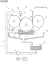
- FIGURE is a side view of a warp sizing apparatus according to an embodiment of the present invention.
- Hereinafter, an embodiment (an example) of a warp sizing apparatus to which the present invention is applied will be described with reference to FIGURE.
- The warp sizing apparatus 1 includes a sizing tank 3 that stores a sizing liquid S, a
sizing roll 11 that is immersed in the sizing liquid S when a warp sheet T is wound thereon, and afirst squeeze roll 13 and asecond squeeze roll 15 circumscribed around thesizing roll 11. However, thesizing roll 11, thefirst squeeze roll 13, and thesecond squeeze roll 15 are rolls having substantially the same dimensions in axis line directions thereof. The warp sizing apparatus 1 further includes a sizingliquid supply device 20 that supplies, from above, the sizing liquid S to a circumscribed position of thesizing roll 11 and thefirst squeeze roll 13. - The
sizing roll 11 is a roll on which the warp sheet T is wound. Thesizing roll 11 is rotatably supported with respect to a frame (not shown) of the warp sizing apparatus 1 by support shafts on both ends of the sizing roll. In addition, thesizing roll 11 is provided such that a lower part thereof is in a state of being immersed in the sizing liquid S stored in the sizing tank 3. - Note that the warp sizing apparatus 1 includes a drive mechanism (not shown) configured to rotationally drive the
sizing roll 11. Thereby, thesizing roll 11 is rotationally driven positively in conformity with advancing of the warp sheet T. The warp sheet T is guided in a form of being wound onto thesizing roll 11, and is immersed in the sizing liquid S and is impregnated with the sizing liquid S during such guiding. - The
second squeeze roll 15 is a roll for squeezing the sizing liquid S impregnated in the warp sheet T, and is provided in arrangement of being located on a front side with respect to thesizing roll 11. In addition, thesecond squeeze roll 15 is rotatably supported with respect to the frame by support shafts on both ends of the second squeeze roll, in a direction in which the axis line direction of the second squeeze roll is made to coincide with the axis line direction of the sizing roll 11 (a width direction of the warp sizing apparatus 1). Note that thesecond squeeze roll 15 is supported with respect to the frame via a pressing mechanism (not shown), and is provided to be circumscribed in a state of being pressed against thesizing roll 11. Therefore, thesecond squeeze roll 15 is adapted to rotate as thesizing roll 11 is rotationally driven as described above. - The warp sheet T wound on the
sizing roll 11 as described above passes between thesizing roll 11 and thesecond squeeze roll 15 circumscribed as described above, and is then pulled out toward an outside. Further, when passing between thesizing roll 11 and the second squeeze roll 15 in this way, the extra sizing liquid S is squeezed from the warp sheet T impregnated with the sizing liquid S as described above. - The
first squeeze roll 13 is provided in arrangement of being located on a rear side with respect to thesizing roll 11. Thefirst squeeze roll 13 is also rotatably supported with respect to the frame by support shafts on both ends of the first squeeze roll, in a direction in which the axis line direction of the first squeeze roll is made to coincide with the width direction. In addition, thefirst squeeze roll 13 is also rotatably supported with respect to the frame via the pressing mechanism and is circumscribed in a state of being pressed against thesizing roll 11, like thesecond squeeze roll 15. Therefore, thefirst squeeze roll 13 is also adapted to rotate as thesizing roll 11 is rotationally driven. - Note that the sizing tank 3 is a housing with an open upper surface and is formed by a bottom plate 4, front and rear end walls 5 and 6, and left and right side walls (not shown). In addition, the sizing tank 3 is provided such that the front end wall 5 is located slightly in front of a circumscribed position of the
sizing roll 11 and thesecond squeeze roll 15 in a front-rear direction of the warp sizing apparatus 1. Further, the sizing tank 3 has such a size in the front-rear direction that the rear end wall 6 is located behind the circumscribed position of thesizing roll 11 and thefirst squeeze roll 13. Asupply unit 40 for supplying the sizing liquid S into the sizing tank 3 is provided in the sizing tank 3. - Further, in the warp sizing apparatus 1, the
first squeeze roll 13 is circumscribed around thesizing roll 11 as described above, and a wedge-shaped region, which is a wedge-shaped gap, is formed between thesizing roll 11 and the first squeeze roll 13 (above the circumscribed position). In addition, the sizingliquid supply device 20 for supplying the sizing liquid S toward the wedge-shaped region is provided above the wedge-shaped region. The sizingliquid supply device 20 includes a sizing liquid pipe 22 extending along the axis line direction of the sizingroll 11 and anozzle 24 attached to the sizing liquid pipe 22. - In addition, the warp sizing apparatus 1 is provided with a
supply tank 30, which is a supply source of the sizing liquid S, and a pump P connected to thesupply tank 30 and delivering the sizing liquid S in thesupply tank 30. In addition, thesupply unit 40 in the sizing tank 3 and the sizing liquid pipe 22 in the sizingliquid supply device 20 are connected to the pump P via asupply pipe 32. Thereby, the sizing liquid S delivered from the pump P is supplied to the sizing tank 3, the sizing liquid S is stored in the sizing tank 3, and is supplied to the wedge-shaped region to form a sizingliquid pool 18 in the wedge-shaped region. - Note that the
supply pipe 32 includes amain pipe 33 with one end connected to the pump P, and afirst branch pipe 34 and asecond branch pipe 35 branched from themain pipe 33. Further, thefirst branch pipe 34 and thesecond branch pipe 35 have substantially the same pipe diameters. In addition, thesupply pipe 32 is connected to thesupply unit 40 in the sizing tank 3 via thefirst branch pipe 34, and is connected to the sizing liquid pipe 22 in the sizingliquid supply device 20 via thesecond branch pipe 35. - In addition, in the warp sizing apparatus 1, the warp sheet T is guided in the form of being wound onto the
first squeeze roll 13, passes between the sizingroll 11 and thefirst squeeze roll 13 circumscribed as described above, and is then wound on the sizingroll 11 as described above. Further, the warp sheet T is impregnated with the sizing liquid S by passing through the sizingliquid pool 18 when passing between the sizingroll 11 and thefirst squeeze roll 13 in this way. Then, when the warp sheet T impregnated with the sizing liquid S in this way passes between the sizingroll 11 and thefirst squeeze roll 13, the extra sizing liquid S is squeezed from the warp sheet T. - Note that the warp sizing apparatus 1 includes a
collection box 50 that receives the sizing liquid S overflowing from the sizing tank 3 as the sizing liquid S is supplied as described above. The sizing liquid S overflowing to both sides of the sizingroll 11 and thefirst squeeze roll 13 as the sizing liquid S is supplied to the sizingliquid pool 18 in the wedge-shaped region is also received by thecollection box 50. Then, in the warp sizing apparatus, the sizing liquid S received in thecollection box 50 flows to thesupply tank 30 and is collected. - In the warp sizing apparatus 1 as described above, according to the present invention, the warp sizing apparatus 1 includes a flow regulating valve in the
first branch pipe 34. In addition, the present embodiment is an example in which a pump capable of adjusting a delivery amount of the sizing liquid S to be delivered to themain pipe 33 is adopted as the pump P connected to thesupply tank 30. - Specifically, the warp sizing apparatus 1 includes a
flow adjustment valve 36 as the flow regulating valve in thefirst branch pipe 34. Note that theflow adjustment valve 36 is a flow regulating valve capable of electrically adjusting (throttling) a flow rate. Theflow adjustment valve 36 is connected to a control device (not shown) provided in the warp sizing apparatus 1, and the flow rate (an opening degree of the valve) is adjusted by the control device. However, the flow regulating valve in the warp sizing apparatus according to the present invention may be another valve capable of adjusting the flow rate, such as a throttle valve configured to manually adjust the flow rate. - The pump P includes a motor M that is a dedicated motor serving as a drive source and whose rotational speed can be changed by inverter control. Thereby, the pump P can change (adjust) the delivery amount of the sizing liquid S to be delivered by changing (adjusting) the rotational speed of the motor M. The warp sizing apparatus 1 further includes an inverter INV for controlling the rotational speed of the motor M. Further, in the warp sizing apparatus 1, the inverter INV is also connected to the control device, and an output frequency and the like of the inverter INV are controlled by the control device.
- Further, in the warp sizing apparatus 1 according to the present embodiment configured in this way, the motor M of the pump P is driven to deliver a preset amount (an amount per unit time, a set amount) of the sizing liquid S. Thereby, the set amount of the sizing liquid S is delivered from the pump P to the
main pipe 33 provided in thesupply pipe 32. Note that the set amount is appropriately set in the control device in consideration of an operation condition, an environmental condition, and the like corresponding to a type of the warp to be sized. - Then, the sizing liquid S delivered to the
main pipe 33 is divided and flows to the first branch pipe 34 (a sizing tank 3 side) and the second branch pipe 35 (a sizingliquid supply device 20 side). However, since thefirst branch pipe 34 is provided with theflow adjustment valve 36, and the flow rate of the sizing liquid S is in a state of being reduced by theflow adjustment valve 36, a flow rate of the sizing liquid S flowing toward thesecond branch pipe 35 is relatively higher than the flow rate of the sizing liquid S flowing toward thefirst branch pipe 34. - Therefore, according to the warp sizing apparatus 1, since a sufficient amount of the sizing liquid S flows to the
second branch pipe 35 for supplying the sizing liquid S to the sizingliquid supply device 20 provided at a high position, there is no need to adopt a large-capacity pump to supply an appropriate amount of the sizing liquid S to the sizingliquid supply device 20 side, and a device cost and a running cost can be reduced. - Note that in the warp sizing apparatus, when there is a concern that an amount of the sizing liquid S stored in the sizing tank 3 is insufficient for a reason that a consumption amount of the sizing liquid S increases with a change in the operation condition, it is necessary to increase the amount of the sizing liquid S supplied to the sizing tank 3 side as a countermeasure. In this case, when the opening degree of the
flow adjustment valve 36 is simply increased (a throttle amount is decreased), an amount of the sizing liquid S supplied to the sizingliquid supply device 20 side decreases. - In contrast, according to the warp sizing apparatus 1 of the present embodiment, since the pump P can adjust the delivery amount of the sizing liquid S, it is possible to increase the flow rate of the sizing liquid S to the sizing tank 3 side without decreasing the flow rate of the sizing liquid S to the sizing
liquid supply device 20 side as much as possible by changing the delivery amount of the sizing liquid S by the pump P due to the change in the operation condition. Note that a change in the delivery amount is implemented by changing the set amount set in the control device. Further, the change in the set amount may be implemented by, for example, setting "a current setting amount + n%". - In the above, an embodiment (hereinafter, referred to as "the example") of the warp sizing apparatus to which the present invention is applied has been described. However, the present invention is not limited to the configuration described in the example, and can also be implemented by other embodiments (modified embodiments) as described below.
- (1) As for the pump, the pump P according to the example includes the dedicated motor M as the drive source. However, in the present invention, the pump is not limited to the configuration of being driven by the motor in this way, and may be, for example, a pump including another drive unit such as an air-driven pump driven by compressed air.
- Further, the pump P according to the example can adjust the delivery amount of the sizing liquid S. However, the pump according to the present invention may not be able to adjust the delivery amount of the sizing liquid S. That is, for example, in a warp sizing apparatus used in a situation where there is no need to change the operation condition, there is a case where there is no need to adjust the delivery amount of the sizing liquid S by the pump. Therefore, in this case, the pump may not be able to adjust the delivery amount of the sizing liquid S.
- (2) As for the warp sizing apparatus that is the preamble, the warp sizing apparatus 1 according to the example is configured in such a form that the sizing
roll 11 is immersed in the sizing liquid S in the sizing tank 3, and two rolls including the first and second squeeze rolls 13 and 15 are circumscribed around the sizingroll 11 to sandwich the path of the warp sheet T therebetween. However, the warp sizing apparatus to which the present invention is applied is not limited to such a configuration. - For example, the warp sizing apparatus may also be configured such that the second squeeze roll is also immersed in the sizing liquid S in the sizing tank, in addition to the sizing roll. However, in this case, the sizing tank is dimensioned to include the sizing roll and the second squeeze roll in the front-rear direction. In addition, the warp sizing apparatus may also be configured such that only the second squeeze roll is immersed in the sizing liquid S in the sizing tank.
- The present invention is not limited to the above embodiment, and can be variously changed without departing from the gist of the present invention.
-
- 1: warp sizing apparatus
- 3: sizing tank
- 4: bottom plate
- 5: front end wall
- 6: rear end wall
- 11: sizing roll
- 13: first squeeze roll
- 15: second squeeze roll
- 18: sizing liquid pool
- 20: sizing liquid supply device
- 22: sizing liquid pipe
- 24: nozzle
- 30: supply tank
- 32: supply pipe
- 33: main pipe
- 34: first branch pipe
- 35: second branch pipe
- 36: flow adjustment valve
- 40: supply unit
- 50: collection box
- M: motor
- P: pump
- INV: inverter
- S: sizing liquid
- T: warp sheet
Claims (2)
- A warp sizing apparatus (1) comprising:a sizing tank (3) in which a sizing liquid (S) is stored;a sizing roll (11) on which a warp sheet (T) is wound;a squeeze roll (13) circumscribed around the sizing roll (11) to sandwich a path of the warp sheet (T);a sizing liquid supply device (20) configured to supply the sizing liquid (S) to a circumscribed position of the sizing roll (11) and the squeeze roll (13); anda supply pipe (32) in which the sizing liquid (S) delivered from a pump (P) is supplied to the sizing tank (3) and the sizing liquid supply device (20), the supply pipe (32) including a main pipe (33) with one end connected to the pump (P), and a first branch pipe (34) and a second branch pipe (35) branched from the main pipe (33), the first branch pipe (34) being connected to the sizing tank (3), and the second branch pipe (35) being connected to the sizing liquid supply device (20),wherein the first branch pipe (34) is provided with a flow regulating valve (36).
- The warp sizing apparatus (1) according to claim 1, wherein
the pump (P) is a pump capable of adjusting a delivery amount of the sizing liquid (S).
Applications Claiming Priority (1)
| Application Number | Priority Date | Filing Date | Title |
|---|---|---|---|
| JP2022211029A JP2024094475A (en) | 2022-12-28 | 2022-12-28 | Warp sizing device |
Publications (2)
| Publication Number | Publication Date |
|---|---|
| EP4394101A1 true EP4394101A1 (en) | 2024-07-03 |
| EP4394101B1 EP4394101B1 (en) | 2026-02-25 |
Family
ID=89029687
Family Applications (1)
| Application Number | Title | Priority Date | Filing Date |
|---|---|---|---|
| EP23213089.8A Active EP4394101B1 (en) | 2022-12-28 | 2023-11-29 | Warp sizing apparatus |
Country Status (3)
| Country | Link |
|---|---|
| EP (1) | EP4394101B1 (en) |
| JP (1) | JP2024094475A (en) |
| CN (2) | CN118257077A (en) |
Citations (3)
| Publication number | Priority date | Publication date | Assignee | Title |
|---|---|---|---|---|
| CH421878A (en) * | 1964-05-25 | 1966-10-15 | Cilander Ag | Device for wet treatment, in circulation or throughput, of a flat textile web continuously guided over rollers |
| JP2003096657A (en) | 2001-09-26 | 2003-04-03 | Tsudakoma Corp | Warp gluing device |
| EP1302583A2 (en) * | 2001-09-26 | 2003-04-16 | Tsudakoma Kogyo Kabushiki Kaisha | Method of removing bubbles and floating matters from sizing tank included in slasher |
-
2022
- 2022-12-28 JP JP2022211029A patent/JP2024094475A/en active Pending
-
2023
- 2023-11-28 CN CN202311606738.8A patent/CN118257077A/en active Pending
- 2023-11-28 CN CN202323227910.7U patent/CN221398334U/en active Active
- 2023-11-29 EP EP23213089.8A patent/EP4394101B1/en active Active
Patent Citations (3)
| Publication number | Priority date | Publication date | Assignee | Title |
|---|---|---|---|---|
| CH421878A (en) * | 1964-05-25 | 1966-10-15 | Cilander Ag | Device for wet treatment, in circulation or throughput, of a flat textile web continuously guided over rollers |
| JP2003096657A (en) | 2001-09-26 | 2003-04-03 | Tsudakoma Corp | Warp gluing device |
| EP1302583A2 (en) * | 2001-09-26 | 2003-04-16 | Tsudakoma Kogyo Kabushiki Kaisha | Method of removing bubbles and floating matters from sizing tank included in slasher |
Also Published As
| Publication number | Publication date |
|---|---|
| EP4394101B1 (en) | 2026-02-25 |
| CN118257077A (en) | 2024-06-28 |
| JP2024094475A (en) | 2024-07-10 |
| CN221398334U (en) | 2024-07-23 |
Similar Documents
| Publication | Publication Date | Title |
|---|---|---|
| US2677991A (en) | Stock inlet for papermaking machines | |
| KR20140097242A (en) | Coating device and coating method | |
| CN104185557A (en) | Supply systems for inkjet printers | |
| US9463933B2 (en) | Hydraulic drive system and method for driving a belt conveyor | |
| US7694642B2 (en) | Device for applying a liquid mixture to web-shaped printing material | |
| US20200368837A1 (en) | Wire electric discharge machining method and wire electric discharge machine | |
| JP2004344695A (en) | Liquid supply device to coating nozzle | |
| EP4394101B1 (en) | Warp sizing apparatus | |
| DE102004017441B4 (en) | Process for fiber composite separation and spinning preparation machine | |
| US3974949A (en) | Sheet prefeeder forming an overhead stock loop to the input of an incremental feeder for a cupping press | |
| EP3002241A1 (en) | Transverse removal brake for a printed sheet | |
| EP1593628B1 (en) | Device for simultaneously feeding and aligning sheets | |
| US4090469A (en) | Breast roller pivoting | |
| JPH115054A (en) | Method of applying liquid or paste medium on self-traveling base material and device therefor | |
| US3014527A (en) | Stock distributor with adjustable inlet | |
| CN1251280A (en) | Device for supplying fluidic ink to printing machine group for cigarette paper strip | |
| EP1306550B1 (en) | Improved concrete pump with means to automatically adjust the working of the S-valve according to the type of concrete | |
| JPH06329308A (en) | Film take-up device | |
| EP3575458A1 (en) | Air spinning machine | |
| EP0949008B1 (en) | Device for coating sheets and strips | |
| EP4345204A1 (en) | Warp sizing apparatus | |
| CN108385359A (en) | A kind of whole cutting apparatus of textile printing and dyeing cloth | |
| US2589638A (en) | Paper machinery | |
| EP4249659A1 (en) | Warp sizing apparatus | |
| JP2015062853A (en) | Intermittent coating apparatus and intermittent coating method |
Legal Events
| Date | Code | Title | Description |
|---|---|---|---|
| PUAI | Public reference made under article 153(3) epc to a published international application that has entered the european phase |
Free format text: ORIGINAL CODE: 0009012 |
|
| STAA | Information on the status of an ep patent application or granted ep patent |
Free format text: STATUS: THE APPLICATION HAS BEEN PUBLISHED |
|
| AK | Designated contracting states |
Kind code of ref document: A1 Designated state(s): AL AT BE BG CH CY CZ DE DK EE ES FI FR GB GR HR HU IE IS IT LI LT LU LV MC ME MK MT NL NO PL PT RO RS SE SI SK SM TR |
|
| STAA | Information on the status of an ep patent application or granted ep patent |
Free format text: STATUS: REQUEST FOR EXAMINATION WAS MADE |
|
| 17P | Request for examination filed |
Effective date: 20241230 |
|
| GRAP | Despatch of communication of intention to grant a patent |
Free format text: ORIGINAL CODE: EPIDOSNIGR1 |
|
| STAA | Information on the status of an ep patent application or granted ep patent |
Free format text: STATUS: GRANT OF PATENT IS INTENDED |
|
| RIC1 | Information provided on ipc code assigned before grant |
Ipc: D06B 1/14 20060101AFI20250825BHEP |
|
| INTG | Intention to grant announced |
Effective date: 20250923 |
|
| GRAS | Grant fee paid |
Free format text: ORIGINAL CODE: EPIDOSNIGR3 |
|
| GRAA | (expected) grant |
Free format text: ORIGINAL CODE: 0009210 |
|
| STAA | Information on the status of an ep patent application or granted ep patent |
Free format text: STATUS: THE PATENT HAS BEEN GRANTED |
|
| AK | Designated contracting states |
Kind code of ref document: B1 Designated state(s): AL AT BE BG CH CY CZ DE DK EE ES FI FR GB GR HR HU IE IS IT LI LT LU LV MC ME MK MT NL NO PL PT RO RS SE SI SK SM TR |
|
| REG | Reference to a national code |
Ref country code: CH Ref legal event code: F10 Free format text: ST27 STATUS EVENT CODE: U-0-0-F10-F00 (AS PROVIDED BY THE NATIONAL OFFICE) Effective date: 20260225 Ref country code: GB Ref legal event code: FG4D |
|
| REG | Reference to a national code |
Ref country code: DE Ref legal event code: R096 Ref document number: 602023012566 Country of ref document: DE |
|
| REG | Reference to a national code |
Ref country code: IE Ref legal event code: FG4D |