EP4393870A2 - Ammonia fuel cell system capable of fast adsorption-desorption switching by selfevaporation of ammonia and power generation method thereof - Google Patents
Ammonia fuel cell system capable of fast adsorption-desorption switching by selfevaporation of ammonia and power generation method thereof Download PDFInfo
- Publication number
- EP4393870A2 EP4393870A2 EP23211696.2A EP23211696A EP4393870A2 EP 4393870 A2 EP4393870 A2 EP 4393870A2 EP 23211696 A EP23211696 A EP 23211696A EP 4393870 A2 EP4393870 A2 EP 4393870A2
- Authority
- EP
- European Patent Office
- Prior art keywords
- ammonia
- gas
- adsorption
- inlet
- adsorption column
- Prior art date
- Legal status (The legal status is an assumption and is not a legal conclusion. Google has not performed a legal analysis and makes no representation as to the accuracy of the status listed.)
- Granted
Links
Images

Classifications
-
- C—CHEMISTRY; METALLURGY
- C01—INORGANIC CHEMISTRY
- C01B—NON-METALLIC ELEMENTS; COMPOUNDS THEREOF; METALLOIDS OR COMPOUNDS THEREOF NOT COVERED BY SUBCLASS C01C
- C01B3/00—Hydrogen; Gaseous mixtures containing hydrogen; Separation of hydrogen from mixtures containing it; Purification of hydrogen; Reversible storage of hydrogen
- C01B3/02—Production of hydrogen; Production of gaseous mixtures containing hydrogen
- C01B3/04—Production of hydrogen; Production of gaseous mixtures containing hydrogen by decomposition of inorganic compounds
- C01B3/047—Decomposition of ammonia
-
- H—ELECTRICITY
- H01—ELECTRIC ELEMENTS
- H01M—PROCESSES OR MEANS, e.g. BATTERIES, FOR THE DIRECT CONVERSION OF CHEMICAL ENERGY INTO ELECTRICAL ENERGY
- H01M8/00—Fuel cells; Manufacture thereof
- H01M8/06—Combination of fuel cells with means for production of reactants or for treatment of residues
- H01M8/0606—Combination of fuel cells with means for production of reactants or for treatment of residues with means for production of gaseous reactants
- H01M8/0612—Combination of fuel cells with means for production of reactants or for treatment of residues with means for production of gaseous reactants from carbon-containing material
- H01M8/0618—Reforming processes, e.g. autothermal, partial oxidation or steam reforming
-
- B—PERFORMING OPERATIONS; TRANSPORTING
- B01—PHYSICAL OR CHEMICAL PROCESSES OR APPARATUS IN GENERAL
- B01D—SEPARATION
- B01D53/00—Separation of gases or vapours; Recovering vapours of volatile solvents from gases; Chemical or biological purification of waste gases, e.g. engine exhaust gases, smoke, fumes, flue gases, aerosols
- B01D53/02—Separation of gases or vapours; Recovering vapours of volatile solvents from gases; Chemical or biological purification of waste gases, e.g. engine exhaust gases, smoke, fumes, flue gases, aerosols by adsorption, e.g. preparative gas chromatography
-
- B—PERFORMING OPERATIONS; TRANSPORTING
- B01—PHYSICAL OR CHEMICAL PROCESSES OR APPARATUS IN GENERAL
- B01D—SEPARATION
- B01D53/00—Separation of gases or vapours; Recovering vapours of volatile solvents from gases; Chemical or biological purification of waste gases, e.g. engine exhaust gases, smoke, fumes, flue gases, aerosols
- B01D53/02—Separation of gases or vapours; Recovering vapours of volatile solvents from gases; Chemical or biological purification of waste gases, e.g. engine exhaust gases, smoke, fumes, flue gases, aerosols by adsorption, e.g. preparative gas chromatography
- B01D53/04—Separation of gases or vapours; Recovering vapours of volatile solvents from gases; Chemical or biological purification of waste gases, e.g. engine exhaust gases, smoke, fumes, flue gases, aerosols by adsorption, e.g. preparative gas chromatography with stationary adsorbents
-
- B—PERFORMING OPERATIONS; TRANSPORTING
- B01—PHYSICAL OR CHEMICAL PROCESSES OR APPARATUS IN GENERAL
- B01D—SEPARATION
- B01D53/00—Separation of gases or vapours; Recovering vapours of volatile solvents from gases; Chemical or biological purification of waste gases, e.g. engine exhaust gases, smoke, fumes, flue gases, aerosols
- B01D53/02—Separation of gases or vapours; Recovering vapours of volatile solvents from gases; Chemical or biological purification of waste gases, e.g. engine exhaust gases, smoke, fumes, flue gases, aerosols by adsorption, e.g. preparative gas chromatography
- B01D53/04—Separation of gases or vapours; Recovering vapours of volatile solvents from gases; Chemical or biological purification of waste gases, e.g. engine exhaust gases, smoke, fumes, flue gases, aerosols by adsorption, e.g. preparative gas chromatography with stationary adsorbents
- B01D53/0462—Temperature swing adsorption
-
- B—PERFORMING OPERATIONS; TRANSPORTING
- B01—PHYSICAL OR CHEMICAL PROCESSES OR APPARATUS IN GENERAL
- B01J—CHEMICAL OR PHYSICAL PROCESSES, e.g. CATALYSIS OR COLLOID CHEMISTRY; THEIR RELEVANT APPARATUS
- B01J23/00—Catalysts comprising metals or metal oxides or hydroxides, not provided for in group B01J21/00
- B01J23/38—Catalysts comprising metals or metal oxides or hydroxides, not provided for in group B01J21/00 of noble metals
- B01J23/40—Catalysts comprising metals or metal oxides or hydroxides, not provided for in group B01J21/00 of noble metals of the platinum group metals
- B01J23/46—Ruthenium, rhodium, osmium or iridium
- B01J23/462—Ruthenium
-
- H—ELECTRICITY
- H01—ELECTRIC ELEMENTS
- H01M—PROCESSES OR MEANS, e.g. BATTERIES, FOR THE DIRECT CONVERSION OF CHEMICAL ENERGY INTO ELECTRICAL ENERGY
- H01M8/00—Fuel cells; Manufacture thereof
- H01M8/04—Auxiliary arrangements, e.g. for control of pressure or for circulation of fluids
- H01M8/04007—Auxiliary arrangements, e.g. for control of pressure or for circulation of fluids related to heat exchange
- H01M8/04014—Heat exchange using gaseous fluids; Heat exchange by combustion of reactants
- H01M8/04022—Heating by combustion
-
- H—ELECTRICITY
- H01—ELECTRIC ELEMENTS
- H01M—PROCESSES OR MEANS, e.g. BATTERIES, FOR THE DIRECT CONVERSION OF CHEMICAL ENERGY INTO ELECTRICAL ENERGY
- H01M8/00—Fuel cells; Manufacture thereof
- H01M8/04—Auxiliary arrangements, e.g. for control of pressure or for circulation of fluids
- H01M8/04007—Auxiliary arrangements, e.g. for control of pressure or for circulation of fluids related to heat exchange
- H01M8/04037—Electrical heating
-
- H—ELECTRICITY
- H01—ELECTRIC ELEMENTS
- H01M—PROCESSES OR MEANS, e.g. BATTERIES, FOR THE DIRECT CONVERSION OF CHEMICAL ENERGY INTO ELECTRICAL ENERGY
- H01M8/00—Fuel cells; Manufacture thereof
- H01M8/04—Auxiliary arrangements, e.g. for control of pressure or for circulation of fluids
- H01M8/04007—Auxiliary arrangements, e.g. for control of pressure or for circulation of fluids related to heat exchange
- H01M8/04067—Heat exchange or temperature measuring elements, thermal insulation, e.g. heat pipes, heat pumps, fins
- H01M8/04074—Heat exchange unit structures specially adapted for fuel cell
-
- H—ELECTRICITY
- H01—ELECTRIC ELEMENTS
- H01M—PROCESSES OR MEANS, e.g. BATTERIES, FOR THE DIRECT CONVERSION OF CHEMICAL ENERGY INTO ELECTRICAL ENERGY
- H01M8/00—Fuel cells; Manufacture thereof
- H01M8/04—Auxiliary arrangements, e.g. for control of pressure or for circulation of fluids
- H01M8/04082—Arrangements for control of reactant parameters, e.g. pressure or concentration
- H01M8/04201—Reactant storage and supply, e.g. means for feeding, pipes
-
- H—ELECTRICITY
- H01—ELECTRIC ELEMENTS
- H01M—PROCESSES OR MEANS, e.g. BATTERIES, FOR THE DIRECT CONVERSION OF CHEMICAL ENERGY INTO ELECTRICAL ENERGY
- H01M8/00—Fuel cells; Manufacture thereof
- H01M8/06—Combination of fuel cells with means for production of reactants or for treatment of residues
- H01M8/0606—Combination of fuel cells with means for production of reactants or for treatment of residues with means for production of gaseous reactants
-
- H—ELECTRICITY
- H01—ELECTRIC ELEMENTS
- H01M—PROCESSES OR MEANS, e.g. BATTERIES, FOR THE DIRECT CONVERSION OF CHEMICAL ENERGY INTO ELECTRICAL ENERGY
- H01M8/00—Fuel cells; Manufacture thereof
- H01M8/10—Fuel cells with solid electrolytes
- H01M8/1009—Fuel cells with solid electrolytes with one of the reactants being liquid, solid or liquid-charged
-
- H—ELECTRICITY
- H01—ELECTRIC ELEMENTS
- H01M—PROCESSES OR MEANS, e.g. BATTERIES, FOR THE DIRECT CONVERSION OF CHEMICAL ENERGY INTO ELECTRICAL ENERGY
- H01M8/00—Fuel cells; Manufacture thereof
- H01M8/10—Fuel cells with solid electrolytes
- H01M8/1016—Fuel cells with solid electrolytes characterised by the electrolyte material
- H01M8/1018—Polymeric electrolyte materials
-
- C—CHEMISTRY; METALLURGY
- C01—INORGANIC CHEMISTRY
- C01B—NON-METALLIC ELEMENTS; COMPOUNDS THEREOF; METALLOIDS OR COMPOUNDS THEREOF NOT COVERED BY SUBCLASS C01C
- C01B2203/00—Integrated processes for the production of hydrogen or synthesis gas
- C01B2203/02—Processes for making hydrogen or synthesis gas
- C01B2203/0266—Processes for making hydrogen or synthesis gas containing a decomposition step
- C01B2203/0277—Processes for making hydrogen or synthesis gas containing a decomposition step containing a catalytic decomposition step
-
- C—CHEMISTRY; METALLURGY
- C01—INORGANIC CHEMISTRY
- C01B—NON-METALLIC ELEMENTS; COMPOUNDS THEREOF; METALLOIDS OR COMPOUNDS THEREOF NOT COVERED BY SUBCLASS C01C
- C01B2203/00—Integrated processes for the production of hydrogen or synthesis gas
- C01B2203/04—Integrated processes for the production of hydrogen or synthesis gas containing a purification step for the hydrogen or the synthesis gas
- C01B2203/042—Purification by adsorption on solids
- C01B2203/043—Regenerative adsorption process in two or more beds, one for adsorption, the other for regeneration
-
- C—CHEMISTRY; METALLURGY
- C01—INORGANIC CHEMISTRY
- C01B—NON-METALLIC ELEMENTS; COMPOUNDS THEREOF; METALLOIDS OR COMPOUNDS THEREOF NOT COVERED BY SUBCLASS C01C
- C01B2203/00—Integrated processes for the production of hydrogen or synthesis gas
- C01B2203/06—Integration with other chemical processes
- C01B2203/066—Integration with other chemical processes with fuel cells
-
- C—CHEMISTRY; METALLURGY
- C01—INORGANIC CHEMISTRY
- C01B—NON-METALLIC ELEMENTS; COMPOUNDS THEREOF; METALLOIDS OR COMPOUNDS THEREOF NOT COVERED BY SUBCLASS C01C
- C01B2203/00—Integrated processes for the production of hydrogen or synthesis gas
- C01B2203/08—Methods of heating or cooling
- C01B2203/0805—Methods of heating the process for making hydrogen or synthesis gas
- C01B2203/0811—Methods of heating the process for making hydrogen or synthesis gas by combustion of fuel
- C01B2203/0822—Methods of heating the process for making hydrogen or synthesis gas by combustion of fuel the fuel containing hydrogen
-
- C—CHEMISTRY; METALLURGY
- C01—INORGANIC CHEMISTRY
- C01B—NON-METALLIC ELEMENTS; COMPOUNDS THEREOF; METALLOIDS OR COMPOUNDS THEREOF NOT COVERED BY SUBCLASS C01C
- C01B2203/00—Integrated processes for the production of hydrogen or synthesis gas
- C01B2203/16—Controlling the process
- C01B2203/1604—Starting up the process
-
- H—ELECTRICITY
- H01—ELECTRIC ELEMENTS
- H01M—PROCESSES OR MEANS, e.g. BATTERIES, FOR THE DIRECT CONVERSION OF CHEMICAL ENERGY INTO ELECTRICAL ENERGY
- H01M8/00—Fuel cells; Manufacture thereof
- H01M8/04—Auxiliary arrangements, e.g. for control of pressure or for circulation of fluids
- H01M8/04223—Auxiliary arrangements, e.g. for control of pressure or for circulation of fluids during start-up or shut-down; Depolarisation or activation, e.g. purging; Means for short-circuiting defective fuel cells
- H01M8/04225—Auxiliary arrangements, e.g. for control of pressure or for circulation of fluids during start-up or shut-down; Depolarisation or activation, e.g. purging; Means for short-circuiting defective fuel cells during start-up
-
- Y—GENERAL TAGGING OF NEW TECHNOLOGICAL DEVELOPMENTS; GENERAL TAGGING OF CROSS-SECTIONAL TECHNOLOGIES SPANNING OVER SEVERAL SECTIONS OF THE IPC; TECHNICAL SUBJECTS COVERED BY FORMER USPC CROSS-REFERENCE ART COLLECTIONS [XRACs] AND DIGESTS
- Y02—TECHNOLOGIES OR APPLICATIONS FOR MITIGATION OR ADAPTATION AGAINST CLIMATE CHANGE
- Y02E—REDUCTION OF GREENHOUSE GAS [GHG] EMISSIONS, RELATED TO ENERGY GENERATION, TRANSMISSION OR DISTRIBUTION
- Y02E60/00—Enabling technologies; Technologies with a potential or indirect contribution to GHG emissions mitigation
- Y02E60/30—Hydrogen technology
- Y02E60/50—Fuel cells
Definitions
- Afuel cell is a device that converts the chemical energy of fuel directly into electrical energy. Since the fuel cell converts the Gibbs free energy in the chemical energy of the fuel into electrical energy through an electrochemical reaction, it is not limited by the Carnot cycle effect, has high efficiency, and has no noise and pollution during operation. Therefore, from the perspective of saving energy and protecting the ecological environment, fuel cells have good development prospects. Hydrogen is currently the most ideal fuel for fuel cell applications. It has the advantages of no adverse side reactions and only water discharge, but its volumetric energy density is low (10-35 mol L-1 H 2), and its cost, storage and transportation, and safety costs are high . .
- hydrocarbon fuels have a high volumetric energy density (21-49mol L -1 H 2 ), are cheap to manufacture, and are convenient for storage and transportation.
- carbon deposition effects can occur during the reaction to reduce the performance of fuel cells and emit CO 2 . Therefore, the application requirements cannot be met.
- the use of ammonia as fuel has the advantages of high volume energy density (60 mol L -1 H 2 ), low cost, convenient storage and transportation, no carbon deposition effect, and no carbon emissions. It has become a promising solution. Therefore, ammonia fuel cells have received extensive attention.
- Ammonia fuel cells can be divided into direct ammonia fuel cells and indirect ammonia fuel cells according to fuel utilization methods.
- the direct ammonia fuel cell is mainly a solid oxide fuel cell (SOFC), the operating temperature is usually 800-1000 ° C, when ammonia is used as fuel, it can be directly connected to the fuel cell to generate electricity without external reforming, and does not require noble metal catalysis, thermoelectric Cogeneration energy conversion efficiency is high.
- SOFC solid oxide fuel cell
- the indirect ammonia fuel cell uses ammonia as the carrier of hydrogen, replaces the storage and transportation of the existing high-pressure hydrogen storage and transportation through the storage and transportation of low-cost liquid NH 3 , and transports liquid NH 3 to the site where hydrogen is used.
- NH 3 is stored in metals such as Ru and Ni.
- the fuel cell adopts the most mature proton exchange membrane fuel cell (PEMFC) on the market at present, its operating temperature is low (60-80°C), and it starts and stops quickly. Reacting with high concentrations of ammonia to generate NH 4+ ions can easily lead to irreversible attenuation of the performance of proton exchange membrane fuel cells (PEMFC). Ammonia decomposition cannot be 100% completely decomposed under the conditions of industrial equipment, and there is a small amount of residual ammonia.
- PEMFC proton exchange membrane fuel cell
- the ammonia fuel cell system needs to couple a series of component devices such as ammonia decomposition, ammonia removal, and hydrogen fuel cell.
- ammonia adsorption devices temperature swing adsorption (TSA) and pressure swing adsorption (PSA).
- TSA temperature swing adsorption
- PSA pressure swing adsorption
- the adsorbent in the temperature swing adsorption device After the adsorbent in the temperature swing adsorption device is saturated, it needs to be desorbed.
- the desorption methods are mainly divided into online desorption and offline desorption. Online desorption can better realize the recycling of energy, and it is easy to realize the automation of the system, which helps to save operating costs. Therefore, the ammonia removal device of this system adopts temperature swing adsorption, and online desorption is used for desorption.
- the adsorption column device includes at least two adsorption columns arranged in parallel, which are respectively used for the adsorption and desorption of ammonia in a reciprocating cycle.
- the heat exchanger in the system can transfer the heat of the flue gas at the outlet of the outer pipe 14 of the ammonia decomposition reactor 1 to the air at the inlet, or transfer the heat of the hydrogen and nitrogen at the outlet of the inner pipe 11 of the reactor Ammonia to the inlet.
- the unreacted hydrogen and nitrogen gas at the tail end of the fuel cell 8 is passed into the adsorption column 7 saturated with adsorption to purge and desorb the adsorbent, and the flue gas after heat exchange is passed into the adsorption column to be desorbed
- the inner tube of 7 drives the temperature rise of the adsorption column 7 to improve the desorption efficiency.
Landscapes
- Chemical & Material Sciences (AREA)
- Engineering & Computer Science (AREA)
- Chemical Kinetics & Catalysis (AREA)
- General Chemical & Material Sciences (AREA)
- Sustainable Energy (AREA)
- Life Sciences & Earth Sciences (AREA)
- Sustainable Development (AREA)
- Electrochemistry (AREA)
- Manufacturing & Machinery (AREA)
- Combustion & Propulsion (AREA)
- Oil, Petroleum & Natural Gas (AREA)
- Analytical Chemistry (AREA)
- Organic Chemistry (AREA)
- Fuel Cell (AREA)
- Materials Engineering (AREA)
- Health & Medical Sciences (AREA)
- General Health & Medical Sciences (AREA)
- Inorganic Chemistry (AREA)
Abstract
Description
- The invention relates to the technical field of ammonia fuel cells, in particular to an ammonia fuel cell system capable of rapid adsorption and desorption switching by self-evaporation of ammonia and a power generation method thereof.
- Afuel cell is a device that converts the chemical energy of fuel directly into electrical energy. Since the fuel cell converts the Gibbs free energy in the chemical energy of the fuel into electrical energy through an electrochemical reaction, it is not limited by the Carnot cycle effect, has high efficiency, and has no noise and pollution during operation. Therefore, from the perspective of saving energy and protecting the ecological environment, fuel cells have good development prospects. Hydrogen is currently the most ideal fuel for fuel cell applications. It has the advantages of no adverse side reactions and only water discharge, but its volumetric energy density is low (10-35 mol L-1 H 2), and its cost, storage and transportation, and safety costs are high . . Among non-hydrogen fuels, hydrocarbon fuels have a high volumetric energy density (21-49mol L -1 H 2), are cheap to manufacture, and are convenient for storage and transportation. However, carbon deposition effects can occur during the reaction to reduce the performance of fuel cells and emit CO 2. Therefore, the application requirements cannot be met. The use of ammonia as fuel has the advantages of high volume energy density (60 mol L -1 H 2), low cost, convenient storage and transportation, no carbon deposition effect, and no carbon emissions. It has become a promising solution. Therefore, ammonia fuel cells have received extensive attention. Ammonia fuel cells can be divided into direct ammonia fuel cells and indirect ammonia fuel cells according to fuel utilization methods. Among them, the direct ammonia fuel cell is mainly a solid oxide fuel cell (SOFC), the operating temperature is usually 800-1000 ° C, when ammonia is used as fuel, it can be directly connected to the fuel cell to generate electricity without external reforming, and does not require noble metal catalysis, thermoelectric Cogeneration energy conversion efficiency is high. However, the current technology of direct ammonia fuel cells is still immature. The indirect ammonia fuel cell uses ammonia as the carrier of hydrogen, replaces the storage and transportation of the existing high-pressure hydrogen storage and transportation through the storage and transportation of low-cost liquid NH 3 , and transports liquid NH 3 to the site where hydrogen is used. NH 3 is stored in metals such as Ru and Ni. Under the catalysis of the catalyst, it is almost completely decomposed into 75%H 2 +25%N 2 mixed gas, which is directly supplied to the hydrogen fuel cell for power generation, thus developing a new hydrogen utilization route - indirect ammonia fuel cell. In the development of indirect ammonia fuel cells, the high-performance low-temperature ammonia decomposition hydrogen production catalyst and reactor technology and the key technology of high-efficiency and compact indirect ammonia fuel cell system integration are the research focus and technical difficulties. Among them, ammonia decomposition needs to be carried out at high temperature (450-500°C), which can be heated by combustion. Combustion can be divided into direct combustion and catalytic combustion. Catalytic combustion refers to the combustion of combustibles at a lower temperature under the action of a catalyst. Compared with direct combustion, the catalytic combustion temperature is lower, the combustion is relatively complete, and it is safer and more environmentally friendly. The fuel cell adopts the most mature proton exchange membrane fuel cell (PEMFC) on the market at present, its operating temperature is low (60-80°C), and it starts and stops quickly. Reacting with high concentrations of ammonia to generate NH 4+ ions can easily lead to irreversible attenuation of the performance of proton exchange membrane fuel cells (PEMFC). Ammonia decomposition cannot be 100% completely decomposed under the conditions of industrial equipment, and there is a small amount of residual ammonia. In order to ensure the continuous operation of the system, it is necessary to pass the ammonia decomposition tail gas through the ammonia adsorption device to remove residual ammonia (the ammonia concentration must be lower than 0.1ppm) before entering the fuel cell. Therefore, the ammonia fuel cell system needs to couple a series of component devices such as ammonia decomposition, ammonia removal, and hydrogen fuel cell. There are two types of ammonia adsorption devices: temperature swing adsorption (TSA) and pressure swing adsorption (PSA). Among them, the temperature swing adsorption regeneration is thorough, the recovery rate is high, and the product loss is small, and it is usually used in the cycle of removing trace impurities or difficult-to-desorb impurities. After the adsorbent in the temperature swing adsorption device is saturated, it needs to be desorbed. The desorption methods are mainly divided into online desorption and offline desorption. Online desorption can better realize the recycling of energy, and it is easy to realize the automation of the system, which helps to save operating costs. Therefore, the ammonia removal device of this system adopts temperature swing adsorption, and online desorption is used for desorption.
- The existing technology has the following problems: 1) If there is no external heating, the evaporation of ammonia will cause the pipeline to freeze, and the flow rate of ammonia gas will drop rapidly. At present, the electric heating scheme is mainly used. When the amount of ammonia evaporation is large, it absorbs more heat and consumes more energy. 2) The catalytic combustion process is unstable, the temperature is not easy to control, and there is a risk of flame combustion and flame burnback leading to high temperature at the front of the reactor and system failure. 3) The temperature swing adsorption device (TSA) currently on the market mainly uses electric heating for online desorption, which is slow to heat and consumes a lot of electric energy, and it takes a long time (>8h) to cool down after high-temperature desorption to continue adsorption. 4) Waste heat at the back end of the system is wasted, while heating air and ammonia at the front end consumes a lot of electric energy and heat energy, and the energy utilization efficiency of the system is low.
- Aiming at the deficiencies of the prior art, the present invention proposes an ammonia fuel cell system capable of fast adsorption-desorption switching by ammonia self-evaporation .
- The present invention adopts following technical scheme:
- An ammonia fuel cell system capable of rapid adsorption and desorption switching by self-evaporation of ammonia, comprising an ammonia decomposition reactor, an ammonia tank, a first heat exchanger, a fuel tank, a first blower, a second heat exchanger, an adsorption column device, a fuel battery, gas circulation system and tail gas combustion system; the gas outlet end of the ammonia tank communicates with the ammonia gas inlet on the ammonia decomposition reactor through the first heat exchanger, and the decomposition gas outlet on the ammonia decomposition reactor The first heat exchanger is communicated with the adsorption inlet of the adsorption column device , and the product gas generated by the decomposition of ammonia in the ammonia decomposition reactor is preheated by the first heat exchanger to the raw ammonia gas ; The fuel tank communicates with the ammonia decomposition reactor for providing fuel gas to the ammonia decomposition reactor;
- The adsorption gas outlet of the adsorption column device communicates with the hydrogen fuel inlet of the fuel cell to provide H2+N2 mixed gas fuel for the fuel cell, and the stack outlet of the fuel cell circulates through the gas The system communicates with the tail gas inlet of the adsorption column device, and the tail gas outlet of the adsorption column device communicates with the tail gas combustion system;
- The gas outlet end of the first blower passes through the second heat exchanger , it communicates with the fuel gas inlet of the ammonia decomposition reactor, and the flue gas output port of the ammonia decomposition reactor passes through the second heat exchanger Afterwards, it communicates with the flue gas inlet of the adsorption column device, and the flue gas generated by the ammonia decomposition reactor passes through the second heat exchanger to preheat the air discharged by the first blower.
- The ammonia decomposition reactor includes a reactor inner tube and a reactor outer tube, the reactor inner tube is an ammonia decomposition zone filled with an ammonia decomposition catalyst, and the reactor outer tube is a catalytic combustion zone filled with a catalytic Combustion catalyst, the outer tube of the reactor is set on the outside of the inner tube of the reactor, the two ends of the inner tube of the reactor are respectively provided with the inlet of ammonia gas and the outlet of decomposition gas, and the two sides of the outer tube of the reactor are respectively provided with There is a fuel gas inlet and a flue gas output port, the ammonia gas inlet communicates with the decomposition gas outlet, and the fuel gas inlet communicates with the flue gas output port.
- The ammonia decomposition catalyst is a ruthenium-based ammonia decomposition catalyst.
- The mixed gas of water vapor and nitrogen at a temperature of 600 °C- 680 °C produced by the catalytic combustion of hydrogen and oxygen , and the product gas is hydrogen, nitrogen and incompletely decomposed ammonia produced after the catalytic decomposition of ammonia gas mixture.
- The gas circulation system includes a condenser and a gas-water separator, and the tail gas combustion system includes a flame arrester and an exhaust gas burner. The stack outlet of the fuel cell is connected to the condenser, the gas-water separator, and the adsorption The tail gas inlet of the column device is connected, and the tail gas outlet of the adsorption column device is connected to the exhaust gas burner after passing through the flame arrester;
- The air inlet of the adsorption column device communicates with the second external blower, and the second blower is used for rapidly cooling the adsorption column device, and the air outlet of the adsorption column device communicates with the external atmosphere through a pipeline and a valve.
- Preferably, the air outlet of the fuel cell is arranged in a direction close to the ammonia tank.
- The fuel cell is a proton exchange membrane fuel cell.
- The first air blower and the ammonia decomposition reactor.
- The adsorption column device includes at least two adsorption columns arranged in parallel, which are respectively used for the adsorption and desorption of ammonia in a reciprocating cycle.
- Preferably, the adsorption column device includes two adsorption columns arranged in parallel, namely adsorption column A and adsorption column B , one of which is used for the adsorption of ammonia, and the other is used for the desorption of ammonia, and the cycle between the two is repeated. conduct.
- Each of the adsorption columns includes an adsorption chamber provided with an adsorbent and a flue gas pipeline. The adsorption chamber is set outside the flue gas pipeline. /desorption gas outlet, the suction/desorption air inlet and the suction/desorption gas outlet are a pair of communication; the flue gas pipeline is provided with a smoke/air inlet and a smoke/air outlet, the said The smoke/air inlet and the smoke/air outlet are a connected pair;
- When the suction/desorption inlet is connected to the decomposed gas outlet, it is the adsorption inlet of the adsorption column device, and the corresponding adsorption/desorption gas outlet is the adsorption column device. The adsorption gas outlet; when the adsorption/desorption inlet is connected to the stack outlet, it is the tail gas inlet of the adsorption column device, and the corresponding adsorption/desorption outlet The gas port is the tail gas outlet of the adsorption column device;
- When the smoke/air inlet is connected to the smoke output port, it is the smoke inlet of the adsorption column device, and the corresponding smoke/air outlet is the smoke gas of the adsorption column device outlet; when the smoke/air inlet is connected to the second blower, it is the air inlet of the adsorption column device, and the corresponding smoke/air outlet is the air outlet of the adsorption column device .
- The adsorption column device is also provided with a first inlet, a second inlet, a third inlet and a fourth inlet, and the first inlet and the second inlet are respectively connected to the suction through a gas path and a valve arranged on the gas path. The gas/desorption air inlet is connected, and the third inlet and the fourth inlet are respectively connected to the smoke/air inlet through the gas path and the valve provided on the gas path.
- Preferably, spiral fins are provided on the outer wall of the flue gas pipeline .
- A pressure reducing valve and a flow controller are also provided on the pipeline between the gas outlet end of the ammonia tank and the first blower.
- A method for generating electricity in an ammonia fuel cell system capable of rapid adsorption and desorption switching through ammonia self-evaporation, comprising the following steps:
-
S 1. When starting up, blow fuel and preheated air into the reactor outer tube of the ammonia decomposition reactor, and after mixing, a catalytic combustion reaction will occur to generate flue gas, thereby driving the reactor outer tube and the reactor inner tube to heat up; -
S 2. When the inner tube of the reactor rises above 450°C, feed ammonia gas into the reactor inner tube of the ammonia decomposition reactor, and the ammonia gas decomposes under the action of the catalyst to generate hydrogen and nitrogen mixed gas; -
S 3. Pass the mixed gas of hydrogen and nitrogen generated in the inner tube of the reactor into the adsorption column device, and after removing the residual ammonia in the mixed gas of hydrogen and nitrogen, the remaining hydrogen and nitrogen enter the fuel cell, thereby providing fuel cells with fuel and generate electricity. - The step S3 , the hydrogen and nitrogen mixed gas generated in the inner tube of the reactor are passed through the first heat exchanger to the adsorption column device, wherein the first heat exchanger transfers the temperature of the hydrogen nitrogen mixed gas to the ammonia The ammonia gas input from the tank; the flue gas from the outer pipe of the reactor passes through the second heat exchanger and then enters the adsorption column device, and the second heat exchanger converts the heat of the flue gas to the input air of the second blower.
- The method also includes step S 4 , passing the remaining hydrogen and nitrogen in the fuel cell into the adsorption column device for purging and desorption.
- The lithium battery can be used to start the power supply for the system. After the fuel cell starts to generate electricity, it can generate electricity for the lithium battery, and can also supply power for its own load and external load .
- The technical solution of the present invention has the following advantages:
- A. The present invention adopts a system thermal coupling scheme to blow the hot air (50-60°C) from the outlet of the air-cooled stack when the proton exchange membrane fuel cell is in operation to the ammonia tank or the cabinet where the ammonia tank is placed, and the other side of the cabinet wall is arranged with The air vent allows the hot air to be blown out from the outlet of the air-cooled reactor, and discharged from the air vent through the cabinet to increase the air temperature in the cabinet (40-50°C) through thermal convection, thereby heating the ammonia tank and realizing the self-evaporation of ammonia .
- B, the present invention controls the temperature of catalytic combustion by controlling the main influencing factors of catalytic combustion in the ammonia decomposition reactor, i.e. fuel flow (hydrogen-nitrogen mixture), air flow and preheating temperature, so that hydrogen-nitrogen mixture can react in ammonia decomposition The temperature of the high-temperature flue gas generated by catalytic combustion in the reactor is stabilized at 600-680°C, and at the same time, it can prevent the high temperature at the front end of the ammonia decomposition reactor caused by the flame burning back .
- C. The present invention adopts the scheme of alternate adsorption and desorption of double adsorption columns, and the online self-desorption of the adsorption columns can be realized by controlling the direction of the gas and the temperature rise and fall of the adsorption columns. The adsorption column adopts the structure of inner tube (flue gas pipeline) + outer tube (adsorption chamber). The inner tube is filled with high-temperature flue gas or low-temperature air, and the outer tube is filled with adsorbents and mixed gas of hydrogen, nitrogen and ammonia. The inner tube has helical fins to increase the contact surface area between the inner tube and the outer tube to improve heating or cooling efficiency. When the adsorption column A in the adsorption column device is adsorbed, the adsorption column B is desorbed, and the mixed gas of hydrogen, nitrogen and ammonia from the decomposition gas outlet of the ammonia decomposition reactor enters the adsorption column A through valve control. At this time, the adsorption column A should be at a low temperature. (10-30°C) to maintain a good adsorption capacity; the tail gas (hydrogen, nitrogen, water) at the outlet of the stack passes through the condenser and the water vapor separator, and the condensed water is discharged, and the remaining hydrogen and nitrogen are passed into the desorption state In the outer tube of the adsorption column B to realize the purging and desorption of the adsorbent in the adsorption column B. Through valve control, the high-temperature flue gas from the hot gas outlet of the second heat exchanger enters the flue gas pipeline of the adsorption column B to heat the adsorption column B, so that the adsorption column maintains a high temperature to improve the desorption effect. In addition, the present invention can be equipped with an electric heating rod in the adsorption column to realize rapid temperature rise of the adsorption column. Before the adsorption of adsorption column A is saturated, low-temperature air is blown into the inner tube of adsorption column B by the second blower in advance to realize rapid cooling of the high-temperature adsorption column and prepare for adsorption. The desorbed tail gas enters the waste gas burner for combustion to avoid tail gas pollution .
- D. In the present invention, heat exchangers are installed at the ammonia inlet of the reactor and the hydrogen and nitrogen outlet of the reactor to exchange the heat of high temperature hydrogen and nitrogen (400-500°C) to the imported ammonia (finally heated to 200-300°C) ; A heat exchanger is installed at the air inlet of the reactor and the flue gas outlet of the reactor to transfer the heat of the high-temperature flue gas (500-600°C) at the reactor outlet to the inlet air (finally heated to 250-350 °C), Thereby effectively improving the thermal efficiency of the system. The high-temperature flue gas is a mixture of water vapor generated by catalytic combustion of hydrogen and oxygen and nitrogen that does not participate in the reaction. The high-temperature flue gas can provide energy for ammonia decomposition.
- In order to illustrate the specific implementation of the present invention more clearly, the accompanying drawings used in the specific implementation will be briefly introduced below. Obviously, the accompanying drawings in the following description are some implementations of the present invention, which are common to those skilled in the art. As far as the skilled person is concerned, other drawings can also be obtained based on these drawings on the premise of not paying creative work.
-
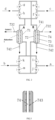
Fig. 1 is a schematic diagram of the overall structure of the ammonia fuel cell system capable of rapid adsorption and desorption switching by ammonia self-evaporation of the present invention ; - representation of adsorption column device in the present invention ;
-
Fig. 3 is a schematic diagram of the position of the fins in the adsorption column in the present invention. - The markings in the figure are as follows:
- 1- Ammonia decomposition reactor, 11- Reactor inner pipe , 12- Ammonia gas inlet , 13-Decomposition gas outlet, 14- Reactor outer pipe , 15- Fuel gas inlet, 16- Flue gas outlet;
- 2-Ammonia tank; 3- First heat exchanger; 4- Fuel tank ; 5- First blower; 6- Second heat exchanger;
- 7- Adsorption column device, 7 1- Adsorption column A, 7 2- Adsorption column B, 7 3-Adsorption chamber, 7 31-Aspiration/desorption inlet, 7 32-Aspiration/desorption gas outlet, 7 4- Flue gas pipeline, 7 41- smoke/air inlet, 7 42- smoke/air outlet, 743-fin ;
- 8- fuel cell, 81- hydrogen fuel inlet, 82- stack outlet;
- 9- gas circulation system, 9 1- condenser, 9 2- gas-water separator;
- 1 0- tail gas combustion system, 1 01- flame arrester, 1 02- exhaust gas burner;
- 2 0- preheater ; 30- second blower ; 40- pressure reducing valve; 50- flow controller;
- a- first inlet; b - second inlet; c - third inlet; d - fourth inlet; e - first valve; f- second valve; g - third valve; h - fourth valve; i- Fifth valve; j - sixth valve; k - seventh valve; m - eighth valve.
- The technical solutions of the present invention will be clearly and completely described below in conjunction with the accompanying drawings. Apparently, the described embodiments are part of the embodiments of the present invention, but not all of them. Based on the embodiments of the present invention, all other embodiments obtained by persons of ordinary skill in the art without making creative efforts belong to the protection scope of the present invention.
- As shown in
Figure 1 andFigure 2 , the present invention provides an ammonia fuel cell system capable of rapid absorption and desorption switching of ammonia self-evaporation, including anammonia decomposition reactor 1, anammonia tank 2 for supplying ammonia, and afirst heat exchanger 3. Fuel tank 4 for providing fuel,first blower 5 for providing oxygen for fuel combustion,second heat exchanger 6,adsorption column device 7,fuel cell 8,gas circulation system 9 and tailgas combustion system 1 0 ,ammonia tank 2 The gas outlet end of thefirst heat exchanger 3 passes through the cold air inlet and outlet of thefirst heat exchanger 3 successively through the pipeline, and then communicates with theammonia gas inlet 1 2 on theammonia decomposition reactor 1 , and thedecomposition gas outlet 1 3 on theammonia decomposition reactor 1 is successively connected by the pipe After passing through the hot gas inlet and outlet of thefirst heat exchanger 3 , it is connected with the adsorption inlet of theadsorption column device 7, and the product gas generated by the decomposition of ammonia gas in theammonia decomposition reactor 1 passes through thefirst heat exchanger 3 to the raw material ammonia gas. Carry out preheating, the adsorption gas outlet ofadsorption column device 7 is communicated with the hydrogenfuel inlet port 81 offuel cell 8 , and the product gas thatammonia decomposition reactor 1 produces is byadsorption column device 7 adsorption removal residual NH 3 After, H 2 + N 2 mixed gas is passed into thefuel cell 8 as fuel; thestack outlet 82 of thefuel cell 8 communicates with the exhaust gas inlet of theadsorption column device 7 through thegas circulation system 9 , and the exhaust gas outlet of theadsorption column device 7 It communicates with the tailgas combustion system 10 ; wherein, the flue gas after combustion in theammonia decomposition reactor 1 is a mixed gas of water vapor and nitrogen at 300-400 °C, which is used to provide thermal energy for subsequent thermal decomposition. The gas outlet end of thefirst blower 5 passes through the cold air inlet and outlet of thesecond heat exchanger 6 successively by means of pipelines, and after merging with the fuel tank 4 gas outlet pipelines, it is connected to thefuel gas inlet 15 of theammonia decomposition reactor 1 ; wherein , thefirst blower 5 can introduce air to theammonia decomposition reactor 1, and then provide oxygen to theammonia decomposition reactor 1, and the fuel in the fuel tank 4, such as hydrogen-nitrogen mixture, or other fuel gas, uses oxygen as a combustion aid in ammonia Combustion in thedecomposition reactor 1 produces flue gas, which provides heat energy for the decomposition of ammonia; the fluegas output port 16 of theammonia decomposition reactor 1 passes through the hot gas inlet and outlet of thesecond heat exchanger 6 in turn through the pipeline, and then connects with the adsorption column device The flue gas inlet of 7 is connected, and the flue gas discharged from the fluegas output port 16 passes through thesecond heat exchanger 6 to preheat the air blown in from thefirst blower 5, and then enters theadsorption column device 7, and the adsorption column The adsorbent in thedevice 7 undergoes thermal desorption. The air pipeline between thesecond heat exchanger 6 and thefuel gas inlet 15 is also provided with apreheater 20, and the air blown in from thefirst blower 5 passes through thesecond heat exchanger 6 after heat exchange, and then passes through the preheater. 20 is further preheated so that the preheating temperature reaches 300-450 ° C. Preferably, thepreheater 20 is located between thesecond heat exchanger 6 and thefuel inlet 15 of theammonia decomposition reactor 1 , so that It is beneficial to save the energy consumed by the heating of the preheater. Thefuel cell 8 is selected as a proton exchange membrane fuel cell, and the air outlet of thefuel cell 8 is set towards the direction close to theammonia tank 2, and the outlet of the air-cooled stack blows to theammonia tank 2 or the cabinet where theammonia tank 2 is placed during its operation. - The present invention adopts a system thermal coupling scheme to blow the hot air (50-60°C) from the outlet of the air-cooled stack during the operation of the proton exchange membrane fuel cell to the ammonia tank or the cabinet where the ammonia tank is placed, and the other side of the cabinet wall is arranged with a vent , so that the hot air can be blown out from the outlet of the air-cooled reactor, discharged from the vent through the cabinet, and the temperature of the air in the cabinet (40-50°C) can be increased by thermal convection, thereby heating the ammonia tank and realizing the self-evaporation of ammonia. In addition, the present invention controls the temperature of the catalytic combustion by controlling the main influencing factors of the catalytic combustion in the
ammonia decomposition reactor 1, i.e. the fuel flow rate, the air flow rate and the preheating temperature, so that the hydrogen-nitrogen mixture gas is catalytically combusted in theammonia decomposition reactor 1 The temperature of the generated high-temperature flue gas is 600-680°C to fully decompose the ammonia gas in the ammonia reactor, maintain the reactivity of the catalyst in the ammonia reactor, and prevent the high temperature at the front end of theammonia decomposition reactor 1 caused by flame burnback. Afirst heat exchanger 3 is arranged on theammonia gas inlet 1 2 pipeline of theammonia decomposition reactor 1 and the ammoniadecomposition gas outlet 1 3 pipeline , and thefirst heat exchanger 3 can exchange the heat of the high-temperature product at 400-500°C The heat is given to the ammonia gas discharged from theammonia tank 2 flowing in from the inlet of the ammonia reactor, and finally the ammonia gas flowing in from the inlet of the ammonia decomposition reactor is heated to 200-300°C, wherein the main products of ammonia decomposition are hydrogen, nitrogen and The mixed gas of undecomposed ammonia; on the air inlet pipeline ofammonia decomposition reactor 1 and on theflue gas outlet 16 , be provided with thesecond heat exchanger 6 , thesecond heat exchanger 6 can theflue gas outlet 16 The 500-600°C heat of the exhausted flue gas is transferred to the inlet air, and finally heats the inlet air to 250-350 °C, thereby effectively improving the thermal efficiency of the system and reducing energy loss . - Further, the
ammonia decomposition reactor 1 includes a reactorinner pipe 11 and a reactorouter pipe 14 , and the reactorinner pipe 11 is an ammonia decomposition zone, which is filled with an ammonia decomposition catalyst. Preferably, the selected ammonia decomposition catalyst is A highly active ruthenium-based catalyst with a working temperature of 450-500°C has high ammonia decomposition performance, which can reduce energy consumption while ensuring complete decomposition of ammonia; theouter tube 1 to 4 of the reactor is a catalytic combustion zone, which is filled with catalytic combustion catalysts , the reactorouter tube 1 4 is set on the outside of the reactorinner tube 1 1 , the reactorinner tube 1 1 is provided with anammonia gas inlet 1 2 and adecomposition gas outlet 1 3 , and the reactorouter tube 1 4 is provided with afuel gas inlet 1 5 andflue gas outlet 16. Whereinammonia decomposition reactor 1 is externally connected with fuel tank 4, and fuel tank 4 can provide fuel gas, such as hydrogen-nitrogen mixed gas as fuel; The high-temperature air is mixed into theouter tube 1 4 of the reactor, and the catalytic combustion reaction occurs under the action of the catalytic combustion catalyst to generate high temperature (600°C-680°C) to heat theinner tube 1 1 of the reactor to provide ammonia in theammonia decomposition reactor 1 The heat required for decomposition. Certainly, also can make inner tube as catalytic combustion zone, outer tube as ammonia decomposition zone; When inner tube was as catalytic combustion zone, outer tube was as ammonia decomposition zone; It is the same when the tube is used as the ammonia decomposition zone and the outer tube is used as the catalytic combustion zone. - In the present invention, the air far exceeding the fuel is sent into the reactor
outer pipe 14 through thefirst blower 5, and the temperature of the catalytic combustion can be kept stable by adjusting the amount of air sent in by thefirst blower 5 through the catalytic combustion temperature. When the air is less than a certain value, the supply of fuel is stopped and the heating of thepreheater 20 is stopped , so as to avoid flame combustion or explosion in the catalytic combustion. In addition, the present invention can realize the automation of temperature monitoring and air volume regulation through programming. - The
gas circulation system 9 includes acondenser 91 and a gas-water separator 92 , the tailgas combustion system 10 includes aflame arrester 101 and anexhaust gas burner 102 , and thestack outlet 82 of thefuel cell 8 is connected to thecondenser 91 and the gas-water separator 92 in sequence After that, it communicates with the exhaust gas inlet of theadsorption column device 7, and the exhaust gas outlet of theadsorption column device 7 passes through theflame arrester 101 and then communicates with theexhaust gas burner 102. The H2O+H2 + N2 produced by thefuel cell 8 after the reaction The H 2 O in the tail gas mixture is condensed and liquefied by thecondenser 91, separated and discharged by the gas-water separator 92, and the remaining H 2 +N 2 tail gas enters the adsorption column device 7 to desorb the NH 3 in the adsorbent, the desorbed exhaust gas enters theexhaust gas burner 102 for combustion. The air inlet of theadsorption column device 7 communicates with the externalsecond blower 30 , and thesecond blower 30 is used for rapidly cooling theadsorption column device 7, and the air outlet of theadsorption column device 7 communicates with the outside atmosphere through a pipeline and a valve. - As shown in
Figure 2 , theadsorption column device 7 includes two adsorption columns arranged in parallel, which are respectively anadsorption column A 71 and anadsorption column B7 2, one of which is used for the adsorption of ammonia, and the other is used for the desorption of ammonia. cyclically in between. Each adsorption column includes anadsorption cavity 73 with adsorbent and aflue gas pipeline 74 , theadsorption cavity 73 is set on the outside of theflue gas pipeline 74 , and the adsorption column adopts an inner tube (flue gas pipeline 74) + an outer tube (adsorption cavity 73) structure, the inner tube is filled with high-temperature flue gas or low-temperature air, and the outer tube is filled with adsorbent and mixed gas of hydrogen, nitrogen and ammonia. The mixed gas discharged from thedecomposition gas outlet 13 of theammonia decomposition reactor 1 enters an adsorption column in theadsorption column device 7 , the ammonia in the mixed gas is absorbed by the adsorbent in the adsorption column, and the H after the ammonia is removed The +N 2 mixed gas enters thefuel cell 8 through thehydrogen fuel inlet 8 1 as fuel, and desorption and desorption are performed after the adsorption amount of ammonia in the adsorbent reaches a certain level. Spiral fins are also provided on theflue gas pipeline 74 of theadsorption column device 7 to increase the contact surface area of the inner tube and the outer tube and improve heating or cooling efficiency, and valves are installed in the system gas circuit. When the desorption starts, cut the valve so that the high-temperature flue gas (300-350°C) produced by catalytic combustion flows through theflue gas pipeline 74 of theadsorption column device 7 to heat the adsorption column (200-300°C); when the desorption is about to end , cut the valve and use thesecond blower 30 to blow air into theflue gas pipeline 74 of theadsorption column device 7 , thereby rapidly cooling theadsorption column device 7. Through the gas coupling of the system, the heating and cooling speed of theadsorption column device 7 is increased and the electric heating loss during heating can be reduced. - The
adsorption chamber 73 is provided with a suction/desorption inlet 731 and a suction/desorption outlet 732 , the suction/desorption inlet 731 and the suction/desorption outlet 732 are a connected pair; the flue gas Thepipeline 74 is provided with a smoke/air inlet 7 41 and a smoke/air outlet 7 42 , the smoke/air inlet 7 41 and the smoke/air outlet 7 42 are a connected pair. When the suction/desorption air inlet 731 is connected to thedecomposition gas outlet 13 , it is the adsorption air inlet of theadsorption column device 7, and the corresponding suction/desorption gas outlet 732 is the adsorption of theadsorption column device 7. Gas outlet; when the suction/desorption air inlet 731 is connected to thestack outlet 82 , it is the tail gas inlet of theadsorption column device 7, and the corresponding suction/desorption gas outlet 732 is the adsorption column device. 7 exhaust gas outlet. When the smoke/air inlet 741 is connected to thesmoke output port 16 , it is the smoke inlet of theadsorption column device 7, and the corresponding smoke/air outlet 742 is the smoke outlet of theadsorption column device 7; When the smoke/air inlet 7 41 is connected to thesecond blower 30 , it is the air inlet of theadsorption column device 7, and the corresponding smoke/air outlet 7 42 is the air outlet of theadsorption column device 7. - Further, the
adsorption column device 7 is also provided with a first inlet a, a second inlet b, a third inlet c and a fourth inlet d, and the first inlet a and the second inlet b respectively pass through the gas path and the holes provided on the gas path. The valve is connected to the suction/desorption inlet 731 , and the third inlet c and the fourth inlet d are respectively connected to the smoke/air inlet 741 through the gas circuit and the valve provided on the gas circuit. - In addition, a pressure reducing valve 4 0 and a
flow controller 5 0 are also provided on the pipeline between the gas outlet end of theammonia tank 2 and thefirst blower 5 . - The present invention has following characteristics:
- (1) The self-evaporation of ammonia can be realized: the hot air (50-60°C) from the
outlet 82 of the stack of thefuel cell 8 is blown directly to theammonia tank 2, or blows into the cabinet where theammonia tank 2 is placed, and the air is blown by heat convection. Heating theammonia tank 2 prevents theammonia tank 2 from decreasing the flow rate due to the gasification of the liquid ammonia, absorbing heat and freezing to reduce the pressure of the ammonia at the outlet. Compared with external heating, energy consumption is reduced. - (2) The ammonia decomposition reactor adopts an inner tube + outer tube structure, which can carry out catalytic combustion and decomposition of ammonia at the same time. The reactor
inner tube 1 1 is an ammonia decomposition zone, which is filled with an ammonia decomposition catalyst (such as a highly active ruthenium-based catalyst, which can achieve a higher ammonia decomposition conversion rate), and the reactorouter tube 1 4 is a catalytic combustion zone, which is filled with Catalytic combustion catalyst, the reactorouter tube 1 4 is set on the outside of the reactorinner tube 1 1 , the reactorinner tube 1 1 is provided with anammonia gas inlet 1 2 and adecomposition gas outlet 1 3 , and the reactorouter tube 1 4 is equipped withFuel gas inlet 15 andflue gas outlet 16. The fuel (hydrogen-nitrogen mixed gas, or other fuel gas) from the fuel tank 4 is mixed with the preheated high-temperature air into theouter tube 14 of the reactor, and a catalytic combustion reaction occurs under the action of the catalytic combustion catalyst to generate high temperature (600 ° C- 680°C) to heat theinner tube 1 1 of the reactor to provide the heat required for ammonia decomposition in theammonia decomposition reactor 1 . Of course, the inner tube can also be used as a catalytic combustion zone, and the outer tube can be used as an ammonia decomposition zone. - 4 of the
ammonia decomposition reactor 1 through thefirst blower 5, and at the same time, the air sent in by thefirst blower 5 can be adjusted by the catalytic combustion temperature amount to keep the temperature of the catalytic combustion stable. When the air is less than a certain value, the supply of fuel is stopped and the heating of thepreheater 20 is stopped, so as to avoid flame combustion or explosion in the catalytic combustion. In addition, the automation of temperature monitoring and air volume regulation can be realized through programming, which improves the stability of catalytic combustion and the controllability of temperature. - (4) The system of the present invention is equipped with two heat exchangers. After the high-temperature flue gas is heated to the
ammonia decomposition reactor 1, it enters thesecond heat exchanger 6 to exchange heat with the air at the inlet, and the mixed gas of thedecomposition gas outlet 1 of theammonia decomposition reactor 1 enters thefirst heat exchanger 3 and theammonia gas inlet 1 2 Ammonia heat exchange on the pipeline, so as to improve the overall thermal efficiency of the system. - (5) For the adsorption column device, the present invention adopts the scheme of alternate adsorption and desorption of double adsorption columns, and the online self-desorption of the adsorption column can be realized by controlling the direction of the gas and the temperature rise and fall of the adsorption column.
- The system of the present invention is divided into four states during operation, state one: adsorption column A is adsorbed, and adsorption column B is desorbed by heating up; state two: adsorption column A is adsorbed, and adsorption column B is cooled and desorbed; state three: adsorption column A is heated up for desorption, The adsorption column B is adsorbed; state four: the adsorption column A cools down and desorbs, and the adsorption column adsorbs. After the system runs for a certain period of time, it will automatically switch to one, two, three, four... cyclically. In this way, subsequent heating and cooling switching functions are realized.
- Among them, the working status corresponding to each status is as follows:
- State 1: When the adsorption column A is adsorbing, the temperature of the adsorption column B is desorbed. Through the valve control, the ammonia decomposition tail gas (hydrogen, nitrogen, ammonia mixture) enters the outer pipe of the adsorption column A from the first inlet a (the fifth valve i is opened, the sixth valve j, and the seventh valve k are closed), and then the adsorption The adsorption/
desorption gas outlet 7 32 on the column A (at this time, the adsorption gas outlet) enters thefuel cell 8 , and at this time the adsorption column A should be at a low temperature (about 10-30°C) to maintain a good adsorption capacity; The tail gas (mixed gas of hydrogen, nitrogen, and water) at theoutlet 82 passes through thecondenser 91 and thewater vapor separator 92, and the condensed water is discharged, and the remaining hydrogen and nitrogen are passed into the outside of the adsorption column B in the desorption state from the second inlet b. (The eighth valve m is open, the sixth valve j and the seventh valve k are closed) to realize the purging and desorption of the adsorbent in the adsorption column B. After desorption, go to thewaste gas burner 102 from the suction/desorption gas outlet 7 32 (the tail gas outlet at this time) on the adsorption column B. Through valve control, the high-temperature flue gas at the outlet ofheat exchanger 1 enters the inner pipe of adsorption column B from the third inlet c (the first valve e is opened, the second valve f, the third valve g, and the fourth valve h are closed) to heat The adsorption column B keeps the high temperature of the adsorption column to improve the desorption effect, and then goes to theexhaust gas burner 102 through the smoke/air outlet 742 on the adsorption column B. It can be equipped with an electric heating rod to achieve rapid temperature rise of the adsorption column. At this moment, the fan at the fourth entrance d is closed. - State 2: The adsorption column A is adsorbed, and the adsorption column B is cooled to desorb. The fifth valve i, the sixth valve j, the seventh valve k, and the eighth valve m are the same as the state one. Before adsorption column A is saturated, use a fan to blow low-temperature air from the fourth inlet d into the inner tube of adsorption column B in advance (the third valve g is opened, the first valve e, the second valve f, and the fourth valve h are closed) , in order to realize rapid cooling of the high-temperature adsorption column, prepare for adsorption, and then go to the smoke/
air outlet 742 on the adsorption column B to empty. At this time, the high-temperature flue gas is directly bypassed to thewaste gas burner 102 . - State 3: When the adsorption column B is adsorbed, the temperature of the adsorption column A is desorbed. Through the valve control, the ammonia decomposition tail gas (hydrogen, nitrogen, ammonia mixture) enters the outer pipe of the adsorption column B from the first inlet a (the sixth valve j is opened, the fifth valve i, and the eighth valve m are closed), and then by Then enter the
fuel cell 8 through the adsorption/desorption gas outlet 7 32 on the adsorption column B (at this time, the adsorption gas outlet) . At this time, the adsorption column B should be at a low temperature (about 10-30°C) to maintain a good adsorption capacity; the tail gas (hydrogen, nitrogen, water mixed gas) at thestack outlet 82 will The condensed water is drained away, and the remaining hydrogen and nitrogen are passed into the outer tube of the adsorption column A in the desorption state from the second inlet b (the seventh valve k is opened, the fifth valve i, and the eighth valve m are closed), so as to realize the adsorption Purge desorption of adsorbent in column A. After desorption, go to thewaste gas burner 102 from the adsorption/desorption gas outlet 7 32 (the tail gas outlet at this time) on the adsorption column A. Through valve control, the high-temperature flue gas at the outlet ofheat exchanger 1 enters the inner pipe of adsorption column A from the third inlet c (the second valve f is opened, the first valve e, the third valve g, and the fourth valve h are closed) to heat The adsorption column A keeps the high temperature of the adsorption column to improve the desorption effect, and then the smoke/air outlet 742 on the adsorption column A goes to theexhaust gas burner 102. It can be equipped with an electric heating rod to achieve rapid temperature rise of the adsorption column, at this time, the fan at the fourth inlet d is turned off. - State 4: The adsorption column B is adsorbed, and the adsorption column A is cooled and desorbed. The fifth valve i, the sixth valve j, the seventh valve k, and the eighth valve m are the same as the state one. Before adsorption of adsorption column B is saturated, blow low-temperature air from the fourth inlet d into the inner tube of adsorption column A in advance with a fan (the fourth valve h is opened, the first valve e, the second valve f, and the third valve g are closed), in order to realize rapid cooling (<3h) of the high-temperature adsorption column, prepare for adsorption, and then go to the smoke/
air outlet 7 42 on the adsorption column A to evacuate . At this time, the flue gas directly goes to thewaste gas burner 102 through the bypass. - State switching: switch to
state 2 after running for 9 hours instate 1, switch tostate 3 after running instate 2 for 3 hours, switch to state 4 after running instate 3 for 9 hours, switch tostate 1 after running in state 4 for 3 hours...and so on. - Of course, the
adsorption column device 7 can also be filled with adsorbent in the inner tube, and the outer tube can pass high-temperature flue gas or low-temperature air. - The present invention also provides a power generation method of an ammonia fuel cell system capable of rapid adsorption and desorption switching by ammonia self-evaporation, comprising the following steps:
-
S 1. When starting up, fuel and preheated air are blown into the reactorouter pipe 14 of theammonia decomposition reactor 1 , and after mixing, catalytic combustion reaction occurs to generate flue gas, thereby driving the reactorouter pipe 14 and thereaction Tube 11 heats up in the device ; -
S 2. When the reactorinner tube 1 1 rises above 450°C, feed ammonia gas into the reactorinner tube 1 1 of theammonia decomposition reactor 1 , and the ammonia gas decomposes under the action of the catalyst to generate hydrogen and nitrogen mixed gas; -
S 3. Pass the hydrogen and nitrogen mixed gas generated in the reactorinner tube 11 through thefirst heat exchanger 3 and then pass it into theadsorption column device 7. After removing the residual ammonia in the hydrogen and nitrogen mixed gas, the remaining The hydrogen and nitrogen gas enters thefuel cell 8, thereby providing fuel for thefuel cell 8, and generating electric energy; wherein thefirst heat exchanger 3 transfers the temperature of the hydrogen-nitrogen mixture to the ammonia gas input by theammonia tank 2; the reactorouter pipe 1 4 The flue gas passes through thesecond heat exchanger 6 and then enters theadsorption column device 7, and thesecond heat exchanger 6 converts the heat of the flue gas to thesecond blower 3 to input air. - S 4 , passing the remaining hydrogen and nitrogen gas in the
fuel cell 8 into theadsorption column device 7 for purging and desorption. - In order to improve the energy efficiency of the system, the heat exchanger in the system can transfer the heat of the flue gas at the outlet of the
outer pipe 14 of theammonia decomposition reactor 1 to the air at the inlet, or transfer the heat of the hydrogen and nitrogen at the outlet of theinner pipe 11 of the reactor Ammonia to the inlet. In order to realize online desorption, the unreacted hydrogen and nitrogen gas at the tail end of thefuel cell 8 is passed into theadsorption column 7 saturated with adsorption to purge and desorb the adsorbent, and the flue gas after heat exchange is passed into the adsorption column to be desorbed The inner tube of 7 drives the temperature rise of theadsorption column 7 to improve the desorption efficiency. - The present invention can use the lithium battery to start the power supply for the system. After the
fuel cell 8 starts to generate electricity, it can generate electricity for the lithium battery, and can also supply power for its own load and external load . - Apparently, the above-mentioned embodiments are only examples for clear description, rather than limiting the implementation. For those of ordinary skill in the art, other changes or changes in different forms can be made on the basis of the above description. It is not necessary and impossible to exhaustively list all the implementation manners here. However, the obvious changes or changes derived therefrom still fall within the scope of protection of the present invention.
Claims (16)
- An ammonia fuel cell system capable of rapid adsorption and desorption switching by self-evaporation of ammonia, characterized in that it includes an ammonia decomposition reactor (1), an ammonia tank (2), a first heat exchanger (3), a fuel tank (4), the first blower (5), the second heat exchanger (6), the adsorption column device (7), the fuel cell (8), the gas circulation system (9) and the tail gas combustion system (10) ; the ammonia The gas outlet end of the tank (2) communicates with the ammonia gas inlet (1 2 ) on the ammonia decomposition reactor (1) through the first heat exchanger (3) , and the ammonia gas inlet (1 2 ) on the ammonia decomposition reactor (1) The decomposition gas outlet (1 3 ) communicates with the adsorption inlet of the adsorption column device (7 ) through the first heat exchanger (3) , and the product produced by the decomposition of ammonia gas in the ammonia decomposition reactor (1) The raw ammonia gas is preheated through the first heat exchanger (3); the fuel tank (4) communicates with the ammonia decomposition reactor (1) for feeding the ammonia decomposition reactor (1)) to provide fuel gas;The adsorption gas outlet of the adsorption column device (7) communicates with the hydrogen fuel inlet (8 1 ) of the fuel cell (8) to provide H 2 + N 2 mixed gas fuel for the fuel cell ( 8 ), The stack outlet (8 2 ) of the fuel cell (8) communicates with the exhaust gas inlet of the adsorption column device (7) through the gas circulation system ( 9 ), and the exhaust gas of the adsorption column device (7) The gas outlet communicates with the tail gas combustion system (10);passing through the second heat exchanger (6), the gas outlet end of the first blower (5 ) communicates with the fuel gas inlet (1 5 ) of the ammonia decomposition reactor (1) , and the ammonia decomposition reactor (1) The flue gas output port (1 6 ) of (1 ) communicates with the flue gas inlet of the adsorption column device (7) after passing through the second heat exchanger ( 6 ) , and the ammonia decomposition reactor (1) produces The flue gas passes through the second heat exchanger ( 6 ) to preheat the air discharged by the first blower (5).
- The ammonia fuel cell system capable of rapid adsorption and desorption switching by self-evaporation of ammonia according to claim 1 , characterized in that the ammonia decomposition reactor (1) includes a reactor inner tube (1 1 ) and a reactor outer tube tube (1 4 ), the reactor inner tube (1 1 ) is an ammonia decomposition zone filled with an ammonia decomposition catalyst, and the reactor outer tube (1 4 ) is a catalytic combustion zone filled with a catalytic combustion catalyst, The reactor outer tube (1 4 ) is set on the outside of the reactor inner tube (1 1 ), and the two ends of the reactor inner tube (1 1 ) are respectively provided with an ammonia gas inlet (1 2 ) and a decomposition gas inlet (1 2 ). Outlet (1 3 ), fuel gas inlet (1 5 ) and flue gas outlet (1 6 ) are respectively provided on both sides of the reactor outer pipe (1 4 ) , the ammonia gas inlet (1 2) and the The decomposition gas outlet (1 3) is connected, and the fuel gas inlet (1 5 ) is connected with the flue gas output port (1 6 ).
- The ammonia fuel cell system capable of rapid adsorption and desorption switching by self-evaporation of ammonia according to claim 2 , wherein the ammonia decomposition catalyst is a ruthenium-based ammonia decomposition catalyst.
- The ammonia fuel cell system capable of rapid adsorption and desorption switchover by self-evaporation of ammonia according to claim 1 , characterized in that the flue gas is produced by catalytic combustion of hydrogen and oxygen at a temperature between 600 ° C and 680 °C The mixed gas of water vapor and nitrogen , the product gas is the mixed gas of hydrogen, nitrogen and incompletely decomposed ammonia produced after the catalytic decomposition of ammonia.
- The ammonia fuel cell system capable of rapid adsorption and desorption switching by self-evaporation of ammonia according to claim 1 , characterized in that the gas circulation system (9) includes a condenser (91) and a gas-water separator (92), The tail gas combustion system (10) includes a flame arrester (101) and an exhaust gas burner (102), and the stack outlet (82) of the fuel cell (8) is sequentially connected to the condenser (91), gas The water separator ( 92 ) communicates with the exhaust gas inlet of the adsorption column device (7), and the exhaust gas outlet of the adsorption column device (7) passes through the flame arrester (101) and burns with the exhaust gas The device (102) is connected;
Communicates with the external second blower (30), and the second blower (30) is used to rapidly cool the adsorption column device (7), and the adsorption column device The air outlet of (7) communicates with the outside atmosphere through the pipeline and through the valve. - The ammonia fuel cell system capable of rapid adsorption and desorption switching by self-evaporation of ammonia according to claim 1, characterized in that the air outlet of the fuel cell (8) is set in a direction close to the ammonia tank (2) .
- The ammonia fuel cell system capable of rapid adsorption and desorption switching by self-evaporation of ammonia according to claim 1, characterized in that the fuel cell (8) is a proton exchange membrane fuel cell.
- The ammonia fuel cell system capable of rapid adsorption and desorption switching by self-evaporation of ammonia according to claim 1, characterized in that the air between the first blower (5) and the ammonia decomposition reactor (1) There is also a preheater (20) on the pipeline.
- The ammonia fuel cell system capable of fast adsorption and desorption switching by self-evaporation of ammonia according to claim 1, characterized in that the adsorption column device (7) includes at least two adsorption columns arranged in parallel, which are reciprocated respectively for the adsorption and desorption of ammonia.
- The ammonia fuel cell system capable of rapid adsorption and desorption switching by self-evaporation of ammonia according to claim 9 , characterized in that, the adsorption column device (7) includes two adsorption columns arranged in parallel, which are adsorption columns A (71) and adsorption column B (72) , one of which is used for the adsorption of ammonia, and the other is used for the desorption of ammonia, and the cycle between the two is repeated.
- The ammonia fuel cell system capable of rapid adsorption and desorption switching by self-evaporation of ammonia according to claim 9 , characterized in that each of the adsorption columns includes an adsorption chamber (73) equipped with an adsorbent and a flue gas pipeline (74), the adsorption chamber (73) is set on the outside of the flue gas pipeline (74), and the adsorption chamber (73) is provided with a suction/desorption inlet (731), a suction/desorption Attached gas outlet (732), the suction/desorption gas inlet (731) and the suction/desorption gas outlet (732) are a connected pair; the flue gas pipeline (74) is provided with Smoke/air inlet (741) and smoke/air outlet (742 ), the smoke/air inlet (741) and smoke/air outlet (742) are a connected pair;When the suction/desorption inlet (731) is connected to the decomposition gas outlet (13), it is the adsorption inlet of the adsorption column device (7), and the corresponding The suction/desorption gas outlet (732) is the adsorption gas outlet of the adsorption column device (7); when the suction/desorption gas inlet (731) is connected to the stack outlet (82), it is The tail gas inlet of the adsorption column device (7), at this time, the corresponding adsorption/desorption gas outlet (732) is the tail gas outlet of the adsorption column device (7);When the smoke/air inlet (741) is connected to the smoke output port (16 ), it is the smoke inlet of the adsorption column device (7), and the corresponding smoke/air The air outlet (742) is the flue gas inlet of the adsorption column device (7); when the smoke/air inlet (741) is connected to the second blower (30), it is the gas inlet of the adsorption column device (7); The air inlet of the column device (7), at this time, the corresponding smoke/air outlet (742 ) is the air outlet of the adsorption column device (7).
- The ammonia fuel cell system capable of rapid adsorption and desorption switching by self-evaporation of ammonia according to claim 11, characterized in that, the adsorption column device (7) is also provided with a first inlet (a), a second inlet (b), the third inlet (c) and the fourth inlet (d), the first inlet (a) and the second inlet (b) are respectively connected to the suction/The desorption inlet (731) is connected, and the third inlet (c) and the fourth inlet (d) are respectively connected to the smoke/air inlet (741) through the gas path and the valve on the gas path. Pass.
- The ammonia fuel cell system capable of rapid adsorption and desorption switching by self-evaporation of ammonia according to claim 11, characterized in that, the outer wall of the flue gas pipeline (74) is provided with spiral fins (743).
- The ammonia fuel cell system capable of fast adsorption and desorption switching by self-evaporation of ammonia according to claim 1, characterized in that the air outlet between the ammonia tank (2) and the first blower (5) A pressure reducing valve (40) and a flow controller (50) are also provided on the pipeline.
- A method for generating electricity in an ammonia fuel cell system capable of rapid adsorption and desorption switching through self-evaporation of ammonia, comprising the following steps:S 1. When starting up, blow fuel and preheated air into the reactor outer tube (14) of the ammonia decomposition reactor (1), and after mixing, a catalytic combustion reaction will occur to generate flue gas, thereby driving the reactor outer tube (14) and reactor inner tube (11) heat up;S 2. When the reactor inner tube (11) rises above 450°C, feed ammonia gas into the reactor inner tube (11) of the ammonia decomposition reactor (1), and the ammonia gas will be generated under the action of the catalyst. Ammonia decomposes to generate hydrogen and nitrogen mixture;S 3. Pass the hydrogen and nitrogen mixture generated in the reactor inner tube (11) into the adsorption column device (7), and after removing the residual ammonia in the hydrogen and nitrogen mixture, the remaining hydrogen and nitrogen enter the fuel battery (8), so as to provide fuel for the fuel cell (8) and generate electrical energy.
- According to the power generation method of the ammonia fuel cell system in claim 15, it is characterized in that the lithium battery can be used to start the power supply for the system, and after the fuel cell (8) starts to generate electricity, it can generate electricity for the lithium battery, or it can be used for its own load and Power supply for external loads.
Applications Claiming Priority (1)
| Application Number | Priority Date | Filing Date | Title |
|---|---|---|---|
| CN202211566909.4A CN116053538B (en) | 2022-12-07 | 2022-12-07 | Ammonia fuel cell system capable of realizing rapid adsorption and desorption switching by ammonia self-evaporation and power generation method thereof |
Publications (3)
| Publication Number | Publication Date |
|---|---|
| EP4393870A2 true EP4393870A2 (en) | 2024-07-03 |
| EP4393870A3 EP4393870A3 (en) | 2024-08-07 |
| EP4393870B1 EP4393870B1 (en) | 2026-01-14 |
Family
ID=86119011
Family Applications (1)
| Application Number | Title | Priority Date | Filing Date |
|---|---|---|---|
| EP23211696.2A Active EP4393870B1 (en) | 2022-12-07 | 2023-11-23 | Ammonia fuel cell system capable of fast adsorption-desorption switching by selfevaporation of ammonia and power generation method thereof |
Country Status (4)
| Country | Link |
|---|---|
| US (1) | US20240194915A1 (en) |
| EP (1) | EP4393870B1 (en) |
| JP (1) | JP7620947B2 (en) |
| CN (1) | CN116053538B (en) |
Families Citing this family (7)
| Publication number | Priority date | Publication date | Assignee | Title |
|---|---|---|---|---|
| CN117065526A (en) * | 2023-08-16 | 2023-11-17 | 福州大学 | A kind of ammonia decomposition hydrogen production system and hydrogen production method based on membrane separation |
| CN117003198B (en) * | 2023-08-16 | 2025-11-11 | 福州大学 | Ammonia decomposition hydrogen production system and hydrogen production method |
| US20260015227A1 (en) * | 2024-07-11 | 2026-01-15 | Saudi Arabian Oil Company | Ammonia cracking via in-situ nitrogen separation |
| CN119194046A (en) * | 2024-11-28 | 2024-12-27 | 福大紫金氢能科技股份有限公司 | An energy-saving ammonia decomposition system for tail gas circulation supplying annealing furnace |
| CN119400911B (en) * | 2024-12-31 | 2025-02-28 | 福大紫金氢能科技股份有限公司 | Mobile modularized ammonia hydrogen fuel cell system and power generation method |
| CN119400913B (en) * | 2024-12-31 | 2025-09-02 | 福大紫金氢能科技股份有限公司 | A miniaturized ammonia-hydrogen fuel cell system and power generation method thereof |
| CN120237236B (en) * | 2025-04-03 | 2025-12-16 | 华中科技大学 | A fuel cell hybrid power supply system and its interval efficiency regulation method |
Family Cites Families (15)
| Publication number | Priority date | Publication date | Assignee | Title |
|---|---|---|---|---|
| CN104953147B (en) * | 2015-07-02 | 2017-07-25 | 北京建筑大学 | A self-supply hydrogen fuel cell system and its working method |
| JP6938186B2 (en) * | 2017-03-24 | 2021-09-22 | 株式会社Kri | Ammonia fuel power generation system and ammonia fuel supply system |
| JP6996181B2 (en) * | 2017-09-13 | 2022-02-04 | 株式会社豊田自動織機 | Fuel cell system |
| JP2019131454A (en) * | 2018-02-02 | 2019-08-08 | 永井 一弘 | Fuel production system for fuel cell vehicle |
| CN110203882B (en) * | 2019-06-20 | 2023-07-07 | 福大紫金氢能科技股份有限公司 | A kind of ammonia decomposition device and system and hydrogen production method |
| CN110277578A (en) * | 2019-06-20 | 2019-09-24 | 福州大学 | A kind of ammonia fuel cell system and electric device |
| CN111957270B (en) * | 2020-09-03 | 2024-10-22 | 福大紫金氢能科技股份有限公司 | Ammonia decomposition hydrogen production system and hydrogen refueling station system |
| CN112050202B (en) * | 2020-09-03 | 2023-04-28 | 福大紫金氢能科技股份有限公司 | Tubular ammonia decomposition reactor |
| KR102930228B1 (en) * | 2020-10-30 | 2026-02-26 | 에이치디한국조선해양 주식회사 | Fuel cell and vessel comprising the same |
| CN112761826A (en) * | 2020-12-31 | 2021-05-07 | 福州大学化肥催化剂国家工程研究中心 | Supercharged engine and ammonia fuel hybrid power generation system |
| KR102453313B1 (en) * | 2021-03-26 | 2022-10-12 | 대우조선해양 주식회사 | Fuel cell generation system for vessel and vessel including the same |
| CN114420972A (en) * | 2022-01-25 | 2022-04-29 | 中国人民解放军海军工程大学 | PEMFC power generation system using ammonia decomposition gas as raw material |
| CN114628732B (en) * | 2022-03-24 | 2024-03-22 | 北京理工大学 | Solar-assisted fuel cell waste heat recovery integrated system and method |
| CN114687989B (en) * | 2022-03-31 | 2023-01-03 | 福州大学 | Energy-saving on-site hydrogen production hydrogenation station system |
| CN115036539B (en) * | 2022-06-21 | 2024-01-23 | 福州大学 | A fuel cell power generation system and its control method |
-
2022
- 2022-12-07 CN CN202211566909.4A patent/CN116053538B/en active Active
-
2023
- 2023-11-23 EP EP23211696.2A patent/EP4393870B1/en active Active
- 2023-11-24 JP JP2023199316A patent/JP7620947B2/en active Active
- 2023-12-05 US US18/530,195 patent/US20240194915A1/en active Pending
Also Published As
| Publication number | Publication date |
|---|---|
| CN116053538A (en) | 2023-05-02 |
| US20240194915A1 (en) | 2024-06-13 |
| CN116053538B (en) | 2024-04-30 |
| EP4393870A3 (en) | 2024-08-07 |
| EP4393870B1 (en) | 2026-01-14 |
| JP2024082250A (en) | 2024-06-19 |
| JP7620947B2 (en) | 2025-01-24 |
Similar Documents
| Publication | Publication Date | Title |
|---|---|---|
| EP4393870B1 (en) | Ammonia fuel cell system capable of fast adsorption-desorption switching by selfevaporation of ammonia and power generation method thereof | |
| JP7352259B2 (en) | Ammonia fuel cell system and electric equipment | |
| CN113506902B (en) | A hybrid system of solid oxide fuel cell and proton exchange membrane fuel cell using ammonia as fuel | |
| JP2021002512A5 (en) | ||
| CN111498802B (en) | Self-circulation hydrogen generation system and working method thereof | |
| CN113782767B (en) | A comprehensive utilization system of waste heat from reforming hydrogen and oxygen fuel cell ships | |
| CN117810494A (en) | Ammonia fuel cell system and power generation method | |
| KR20130085839A (en) | Heating and cooling system using heat from fuel cell | |
| CN112820915A (en) | Combined CO2Trapped molten carbonate fuel cell system and method of operating same | |
| CN116281853A (en) | A self-heating ammonia hydrogen production system | |
| CN118248897A (en) | Indirect ammonia solid oxide fuel cell system | |
| JP7575643B1 (en) | Ammonia-based solid oxide fuel cell (SOFC) system with heating element heating and method of operation thereof - Patents.com | |
| CN111336510B (en) | Porous medium combustion and fuel cell multistage coupling energy system | |
| CN113937320B (en) | Low-temperature proton exchange membrane fuel cell cogeneration system and method | |
| CN110661014A (en) | Efficient low-concentration gas power generation system and control method thereof | |
| CN210129554U (en) | Ammonia fuel cell system and electric device | |
| CN118807622A (en) | A flexible green ammonia synthesis system | |
| CN117936852A (en) | A direct ammonia fuel cell system | |
| CN116706165A (en) | Tandem type ammonia fuel cell system | |
| CN118669190A (en) | Power generation system of combined cycle unit coupling molten carbonate electrolyzer | |
| CN212387735U (en) | Methanol-water fuel reforming hydrogen production system | |
| CN221947193U (en) | Hydrogen/ammonia fuel energy system coupling fuel cell and gas turbine | |
| CN119400912B (en) | Ammonia hydrogen fuel cell system capable of rapid startup | |
| CN119400913B (en) | A miniaturized ammonia-hydrogen fuel cell system and power generation method thereof | |
| CN223128006U (en) | Flexible green ammonia synthesis system |
Legal Events
| Date | Code | Title | Description |
|---|---|---|---|
| PUAI | Public reference made under article 153(3) epc to a published international application that has entered the european phase |
Free format text: ORIGINAL CODE: 0009012 |
|
| STAA | Information on the status of an ep patent application or granted ep patent |
Free format text: STATUS: THE APPLICATION HAS BEEN PUBLISHED |
|
| AK | Designated contracting states |
Kind code of ref document: A2 Designated state(s): AL AT BE BG CH CY CZ DE DK EE ES FI FR GB GR HR HU IE IS IT LI LT LU LV MC ME MK MT NL NO PL PT RO RS SE SI SK SM TR |
|
| PUAL | Search report despatched |
Free format text: ORIGINAL CODE: 0009013 |
|
| AK | Designated contracting states |
Kind code of ref document: A3 Designated state(s): AL AT BE BG CH CY CZ DE DK EE ES FI FR GB GR HR HU IE IS IT LI LT LU LV MC ME MK MT NL NO PL PT RO RS SE SI SK SM TR |
|
| RIC1 | Information provided on ipc code assigned before grant |
Ipc: B01J 23/46 20060101ALI20240702BHEP Ipc: B01D 53/04 20060101ALI20240702BHEP Ipc: B01D 53/02 20060101ALI20240702BHEP Ipc: H01M 8/22 20060101ALI20240702BHEP Ipc: H01M 8/1004 20160101ALI20240702BHEP Ipc: H01M 8/0606 20160101ALI20240702BHEP Ipc: H01M 8/04014 20160101ALI20240702BHEP Ipc: C01B 3/04 20060101AFI20240702BHEP |
|
| STAA | Information on the status of an ep patent application or granted ep patent |
Free format text: STATUS: REQUEST FOR EXAMINATION WAS MADE |
|
| 17P | Request for examination filed |
Effective date: 20241008 |
|
| RBV | Designated contracting states (corrected) |
Designated state(s): AL AT BE BG CH CY CZ DE DK EE ES FI FR GB GR HR HU IE IS IT LI LT LU LV MC ME MK MT NL NO PL PT RO RS SE SI SK SM TR |
|
| STAA | Information on the status of an ep patent application or granted ep patent |
Free format text: STATUS: EXAMINATION IS IN PROGRESS |
|
| 17Q | First examination report despatched |
Effective date: 20250204 |
|
| GRAP | Despatch of communication of intention to grant a patent |
Free format text: ORIGINAL CODE: EPIDOSNIGR1 |
|
| STAA | Information on the status of an ep patent application or granted ep patent |
Free format text: STATUS: GRANT OF PATENT IS INTENDED |
|
| GRAS | Grant fee paid |
Free format text: ORIGINAL CODE: EPIDOSNIGR3 |
|
| INTG | Intention to grant announced |
Effective date: 20251024 |
|
| GRAA | (expected) grant |
Free format text: ORIGINAL CODE: 0009210 |
|
| STAA | Information on the status of an ep patent application or granted ep patent |
Free format text: STATUS: THE PATENT HAS BEEN GRANTED |
|
| AK | Designated contracting states |
Kind code of ref document: B1 Designated state(s): AL AT BE BG CH CY CZ DE DK EE ES FI FR GB GR HR HU IE IS IT LI LT LU LV MC ME MK MT NL NO PL PT RO RS SE SI SK SM TR |
|
| REG | Reference to a national code |
Ref country code: CH Ref legal event code: F10 Free format text: ST27 STATUS EVENT CODE: U-0-0-F10-F00 (AS PROVIDED BY THE NATIONAL OFFICE) Effective date: 20260114 Ref country code: GB Ref legal event code: FG4D |
|
| REG | Reference to a national code |
Ref country code: DE Ref legal event code: R096 Ref document number: 602023010716 Country of ref document: DE |
|
| REG | Reference to a national code |
Ref country code: IE Ref legal event code: FG4D |
|
| REG | Reference to a national code |
Ref country code: CH Ref legal event code: R17 Free format text: ST27 STATUS EVENT CODE: U-0-0-R10-R17 (AS PROVIDED BY THE NATIONAL OFFICE) Effective date: 20260305 |
|
| REG | Reference to a national code |
Ref country code: NL Ref legal event code: MP Effective date: 20260114 |
|
| PG25 | Lapsed in a contracting state [announced via postgrant information from national office to epo] |
Ref country code: NL Free format text: LAPSE BECAUSE OF FAILURE TO SUBMIT A TRANSLATION OF THE DESCRIPTION OR TO PAY THE FEE WITHIN THE PRESCRIBED TIME-LIMIT Effective date: 20260114 |
|
| REG | Reference to a national code |
Ref country code: AT Ref legal event code: MK05 Ref document number: 1877059 Country of ref document: AT Kind code of ref document: T Effective date: 20260114 |
|
| PG25 | Lapsed in a contracting state [announced via postgrant information from national office to epo] |
Ref country code: RS Free format text: LAPSE BECAUSE OF FAILURE TO SUBMIT A TRANSLATION OF THE DESCRIPTION OR TO PAY THE FEE WITHIN THE PRESCRIBED TIME-LIMIT Effective date: 20260414 |
|
| PG25 | Lapsed in a contracting state [announced via postgrant information from national office to epo] |
Ref country code: ES Free format text: LAPSE BECAUSE OF FAILURE TO SUBMIT A TRANSLATION OF THE DESCRIPTION OR TO PAY THE FEE WITHIN THE PRESCRIBED TIME-LIMIT Effective date: 20260114 |
|
| PG25 | Lapsed in a contracting state [announced via postgrant information from national office to epo] |
Ref country code: PL Free format text: LAPSE BECAUSE OF FAILURE TO SUBMIT A TRANSLATION OF THE DESCRIPTION OR TO PAY THE FEE WITHIN THE PRESCRIBED TIME-LIMIT Effective date: 20260114 |
|
| PG25 | Lapsed in a contracting state [announced via postgrant information from national office to epo] |
Ref country code: GR Free format text: LAPSE BECAUSE OF FAILURE TO SUBMIT A TRANSLATION OF THE DESCRIPTION OR TO PAY THE FEE WITHIN THE PRESCRIBED TIME-LIMIT Effective date: 20260415 |
|
| REG | Reference to a national code |
Ref country code: LT Ref legal event code: MG9D |
|
| PG25 | Lapsed in a contracting state [announced via postgrant information from national office to epo] |
Ref country code: LT Free format text: LAPSE BECAUSE OF FAILURE TO SUBMIT A TRANSLATION OF THE DESCRIPTION OR TO PAY THE FEE WITHIN THE PRESCRIBED TIME-LIMIT Effective date: 20260114 |
|
| PG25 | Lapsed in a contracting state [announced via postgrant information from national office to epo] |
Ref country code: NO Free format text: LAPSE BECAUSE OF FAILURE TO SUBMIT A TRANSLATION OF THE DESCRIPTION OR TO PAY THE FEE WITHIN THE PRESCRIBED TIME-LIMIT Effective date: 20260414 |
|
| PG25 | Lapsed in a contracting state [announced via postgrant information from national office to epo] |
Ref country code: SE Free format text: LAPSE BECAUSE OF FAILURE TO SUBMIT A TRANSLATION OF THE DESCRIPTION OR TO PAY THE FEE WITHIN THE PRESCRIBED TIME-LIMIT Effective date: 20260114 Ref country code: FI Free format text: LAPSE BECAUSE OF FAILURE TO SUBMIT A TRANSLATION OF THE DESCRIPTION OR TO PAY THE FEE WITHIN THE PRESCRIBED TIME-LIMIT Effective date: 20260114 Ref country code: AT Free format text: LAPSE BECAUSE OF FAILURE TO SUBMIT A TRANSLATION OF THE DESCRIPTION OR TO PAY THE FEE WITHIN THE PRESCRIBED TIME-LIMIT Effective date: 20260114 |
|
| PG25 | Lapsed in a contracting state [announced via postgrant information from national office to epo] |
Ref country code: HR Free format text: LAPSE BECAUSE OF FAILURE TO SUBMIT A TRANSLATION OF THE DESCRIPTION OR TO PAY THE FEE WITHIN THE PRESCRIBED TIME-LIMIT Effective date: 20260114 |
|
| PG25 | Lapsed in a contracting state [announced via postgrant information from national office to epo] |
Ref country code: PT Free format text: LAPSE BECAUSE OF FAILURE TO SUBMIT A TRANSLATION OF THE DESCRIPTION OR TO PAY THE FEE WITHIN THE PRESCRIBED TIME-LIMIT Effective date: 20260514 Ref country code: IS Free format text: LAPSE BECAUSE OF FAILURE TO SUBMIT A TRANSLATION OF THE DESCRIPTION OR TO PAY THE FEE WITHIN THE PRESCRIBED TIME-LIMIT Effective date: 20260514 |
|
| PG25 | Lapsed in a contracting state [announced via postgrant information from national office to epo] |
Ref country code: LV Free format text: LAPSE BECAUSE OF FAILURE TO SUBMIT A TRANSLATION OF THE DESCRIPTION OR TO PAY THE FEE WITHIN THE PRESCRIBED TIME-LIMIT Effective date: 20260114 |
|
| PG25 | Lapsed in a contracting state [announced via postgrant information from national office to epo] |
Ref country code: BG Free format text: LAPSE BECAUSE OF FAILURE TO SUBMIT A TRANSLATION OF THE DESCRIPTION OR TO PAY THE FEE WITHIN THE PRESCRIBED TIME-LIMIT Effective date: 20260114 |