EP4393779A1 - Vehicular airbag device - Google Patents
Vehicular airbag device Download PDFInfo
- Publication number
- EP4393779A1 EP4393779A1 EP22861115.8A EP22861115A EP4393779A1 EP 4393779 A1 EP4393779 A1 EP 4393779A1 EP 22861115 A EP22861115 A EP 22861115A EP 4393779 A1 EP4393779 A1 EP 4393779A1
- Authority
- EP
- European Patent Office
- Prior art keywords
- clock
- driver
- rectifying member
- surface part
- airbag device
- Prior art date
- Legal status (The legal status is an assumption and is not a legal conclusion. Google has not performed a legal analysis and makes no representation as to the accuracy of the status listed.)
- Pending
Links
Images




Classifications
-
- B—PERFORMING OPERATIONS; TRANSPORTING
- B60—VEHICLES IN GENERAL
- B60R—VEHICLES, VEHICLE FITTINGS, OR VEHICLE PARTS, NOT OTHERWISE PROVIDED FOR
- B60R21/00—Arrangements or fittings on vehicles for protecting or preventing injuries to occupants or pedestrians in case of accidents or other traffic risks
- B60R21/02—Occupant safety arrangements or fittings, e.g. crash pads
- B60R21/16—Inflatable occupant restraints or confinements designed to inflate upon impact or impending impact, e.g. air bags
- B60R21/20—Arrangements for storing inflatable members in their non-use or deflated condition; Arrangement or mounting of air bag modules or components
- B60R21/217—Inflation fluid source retainers, e.g. reaction canisters; Connection of bags, covers, diffusers or inflation fluid sources therewith or together
-
- B—PERFORMING OPERATIONS; TRANSPORTING
- B60—VEHICLES IN GENERAL
- B60R—VEHICLES, VEHICLE FITTINGS, OR VEHICLE PARTS, NOT OTHERWISE PROVIDED FOR
- B60R21/00—Arrangements or fittings on vehicles for protecting or preventing injuries to occupants or pedestrians in case of accidents or other traffic risks
- B60R21/02—Occupant safety arrangements or fittings, e.g. crash pads
- B60R21/16—Inflatable occupant restraints or confinements designed to inflate upon impact or impending impact, e.g. air bags
- B60R21/20—Arrangements for storing inflatable members in their non-use or deflated condition; Arrangement or mounting of air bag modules or components
- B60R21/203—Arrangements for storing inflatable members in their non-use or deflated condition; Arrangement or mounting of air bag modules or components in steering wheels or steering columns
-
- B—PERFORMING OPERATIONS; TRANSPORTING
- B60—VEHICLES IN GENERAL
- B60R—VEHICLES, VEHICLE FITTINGS, OR VEHICLE PARTS, NOT OTHERWISE PROVIDED FOR
- B60R21/00—Arrangements or fittings on vehicles for protecting or preventing injuries to occupants or pedestrians in case of accidents or other traffic risks
- B60R21/02—Occupant safety arrangements or fittings, e.g. crash pads
- B60R21/16—Inflatable occupant restraints or confinements designed to inflate upon impact or impending impact, e.g. air bags
- B60R21/23—Inflatable members
- B60R21/231—Inflatable members characterised by their shape, construction or spatial configuration
- B60R21/2334—Expansion control features
- B60R21/2346—Soft diffusers
Definitions
- Airbag devices have generally become standard equipment in vehicles in recent years.
- An airbag device is a safety device which is operated in the event of an emergency such as a vehicle collision, retaining and protecting occupants utilizing an airbag cushion which expands and deploys based on gas pressure.
- an airbag cushion of a front airbag must expand and deploy quickly, and must have proper deployment behavior so as to precisely fill a space between the abdomen of the occupant and the steering wheel.
- the above rectifying member can smoothly guide gas received by the roof part to the opening parts.
- the ridge line part and the opening parts when the steering wheel is likened to a clock, are formed along the 12 o'clock and 6 o'clock directions.
- the 6 o'clock direction in particular, is the direction where the abdomen of the driver is when seen from the steering wheel. Therefore, according to the above configuration, gas supplied from the inflator is guided in the direction of the abdomen of the driver by the rectifying member and the airbag cushion can be quickly expanded and deployed between the abdomen of the driver and the steering wheel, thus making is possible to protect the driver adequately.
- the above rectifying member is folded and the edges thereof are stitched together with a prescribed panel in the center thereof, the bottom surface part is formed in a portion that includes the center of the panel, the side surface part is formed by a portion that excludes the bottom surface part of the panel, the roof part is formed by the stitched edges, and the opening parts are formed by not stitching parts of the edges of the panel.
- the rectifying member can be realized using a simple configuration, thus making it possible to reduce material costs and workloads.
- a distance between the center of the bottom surface part and the top part of the aforementioned rectifying member is greater than a distance between the center of the bottom surface part and the upper ends of the opening parts, and end parts on the 12 o'clock and 6 o'clock sides of the clock of the roof part are positioned further outside than a line section that connects the edge of an insertion hole in the bottom surface part to the edge of an opening in the stowing part.
- gas received by the roof part is smoothly guided to the opening parts, and thus the gas flows efficiently into the airbag cushion from the opening parts.
- a width dimension across a direction that connects 12 o'clock and 6 o'clock of the clock in the center of the above panel is larger than a width dimension of the bottom of the stowing part.
- the above plurality of opening parts are formed to open to the same dimensions, and portions of at least half of all of the opening parts can be exposed through the opening in the stowing part.
- the airbag cushion can be efficiently filled with gas from the rectifying member.
- the above rectifying member may also include a plurality of small hole parts that open smaller than opening parts provided in locations that correspond to at least the 9 o'clock and 3 o'clock positions, respectively, of the clock of the side surface part.
- the above plurality of small hole parts, together with the opening parts, make it possible to efficiently distribute gas to every corner of, and thus fill, the airbag cushion.
- the above plurality of small hole parts are provided in locations that are further inside than a line section that connects the center of the bottom surface part to the upper ends of the opening parts, and that are exposed through the opening in the stowing part.
- gas can be discharged through the small hole parts configured as described above in a direction orthogonal to the direction the opening parts discharge gas, gas can be efficiently distributed to every corner of, and thus fill, the airbag cushion.
- the dimensions of the roof part described above may be two or more times the inner diameter of the stowing part in the direction that connects 12 o'clock and 6 o'clock of the clock.
- the aforementioned distance between the center of the bottom surface part and the top part described above may be 65 mm or less when the airbag cushion expands and deploys.
- the above configuration makes it possible to realize a rectifying member where gas flows efficiently in the airbag cushion.
- the head direction of the driver 104 is referred to as up
- the waist direction of the driver 104 is referred to as down
- the directions are referred to the up-down direction when axes on coordinates are depicted.
- the front, back, left, right, up, and down directions with reference to the driver 104 described above are depicted by arrows F (Forward), B (Back), L (Left), R (Right), U (up), and D (down).
- FIG. 1(b) is a diagram depicting a state of the vehicle airbag device 100 after activation.
- the airbag cushion 108 expands and deploys in a round bag shape when seen from a driver seat side.
- the airbag cushion 108 is formed by overlapping and stitching or adhering a plurality of base fabrics configuring a front surface thereof, or by spinning and weaving, or the like, using One-Piece Woven (OPW).
- OPT One-Piece Woven
- FIG. 2 is a diagram depicting an internal configuration of the airbag cushion 108 of FIG. 1(b) .
- FIG. 2 depicts the airbag cushion 108 and the driver 104 of FIG. 1(b) when seen from a side direction.
- a rectifying member 112 is provided inside the airbag cushion 108 of the vehicle airbag device 100.
- the rectifying member 112 regulates a flow of gas from an inflator 126 ( FIG. 3 ) described later, and then distributes the gas into the airbag cushion 108.
- the vehicle airbag device 100 is able to use the rectifying member 112 to quickly and precisely restrain the driver with the airbag cushion.
- FIG. 3 is a cross-sectional view along A-A of the vehicle airbag device 100 of FIG. 1(b) .
- Cross section A-A is a longitudinal cross section along vehicle front-to-back and up-down directions in the position where the rectifying member 112 is provided inside the airbag cushion 108.
- An overview of the configuration of the vehicle airbag device 100 is described below beginning with a description of the rectifying member 112.
- the stowing part 110 is provided in a location that is closer to the center than a rim 114 (see FIG. 1(a) ) of the steering wheel 106.
- the stowing part 110 is configured to include a recessed part 118 formed in the steering wheel 106, a case 120 installed in the recessed part 118, and a cover 122 (see FIG. 1(a) ) that covers the case 120.
- the case 120 has a cylindrical structure (see FIG. 6(a) , and the like), and an opening 124 is formed on the driver side.
- a prescribed tear line with a thinned cross section is provided on the cover 122, which line is designed to split when the airbag cushion 108 expands and deploys.
- the rectifying member 112 is attached to the inside of the airbag cushion 108 so as to cover the inflator 126.
- the rectifying member 112 includes a bottom surface part 144 that is installed on the bottom of the case 120 by the aforementioned retainer 134, and a roof part 146 that deploys in a position on the driver side when seen from the bottom surface part 144. After gas emitted from the inflator 126 is received on the inside of the roof part 146, the rectifying member 112 uses two opening parts 148 and 150 to distribute the gas in the airbag cushion 108.
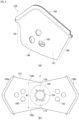
- FIG. 4 is a diagram depicting the rectifying member 112 of FIG. 2 by itself.
- FIG. 4(a) is a perspective view depicting the rectifying member 112.
- the rectifying member 112 has a three-dimensional shape formed by folding a one-sheet panel 152 (see FIG. 4(b) ) made using the same base fabric, or the like, as the airbag cushion 108 (see FIG. 2 , and the like) for material in the center along a center line L1 and then stitching the edges of the panel together.
- a side surface part 147 of the rectifying member 112 is a portion that connects the bottom surface part 144 and the roof part 146, and the opening parts 148 and 150 and small hole parts 160 and 162 (see FIG. 4(b) ) that discharge gas are provided therein.
- the roof part 146 of FIG. 4(a) is formed by overlapping and stitching left and right triangular edges 156a and 156b of the panel 152 (see FIG. 4(b) ) together.
- the opening parts 148 and 150 in the rectifying member 112 are formed by not stitching edges 158a and 158b, which edges stretch left and right from the center of the figure on a top and bottom of the panel 152 of FIG. 4(b) .
- the small hole parts 160 and 162 are also provided between the bottom surface part 144 and the roof part 146.
- the small hole parts 160 and 162 are, together with the opening parts 148 and 150, holes that discharge gas.
- three each of the small hole parts 160 and 162 are provided on both left and right sides when seen from the central insertion hole 154, however, the number thereof to be provided is not limited to this.
- FIG. 5 is a diagram depicting the rectifying member 112 of FIG. 2 from the driver side.
- the opening parts 148 and 150 in the rectifying member 112 are designed so that gas can flow in a specific direction.
- the configuration of the rectifying member is described below by likening the steering wheel 106 to a clock and using time positions on a dial 162 of the clock as examples.
- FIG. 6 is a diagram depicting the rectifying member 112 of FIG. 4 from each direction.
- FIG. 6(a) is a diagram depicting the rectifying member 112 from the 9 o'clock direction of FIG. 5 .
- FIG. 6 also depicts the case 120 (see FIG. 3 ) together with the rectifying member 112.
- the driver 104 may make contact with the airbag cushion 108 to the left or right thereof, which can lead to unexpected injury values for the driver 104.
- the airbag cushion 108 expands non-preferentially in the 3 o'clock and 9 o'clock directions (see FIG. 5 ) using the small diameter small hole parts 160 and 162, a load on and injury value for the driver 104 are reduced when the driver makes contact to the left or right.
- FIG. 7 is a diagram depicting a process whereby the rectifying member 112 of FIG. 6(a) activates.
- FIG. 7(a) is a diagram depicting the rectifying member 112 in an initial deployed state.
- the gas is supplied from the inflator 126, the gas is received by the roof part 146, and the rectifying member 112 deploys by flying out from the opening 124 in the case 120. Because the opening 124 in the case 120 is covered by the cover 122 (see FIG. 1(a) ) at this time, the tear line in the cover 122 is split by the expansion pressure of the rectifying member 112 and the airbag cushion 108.
- FIG. 7(d) is a diagram depicting the rectifying member 112 in a deployed state following the state depicted in FIG. 7(c) .
- the roof part 146 is able to spread out beyond the opening 124 in the case 120 in the 12 o'clock and 6 o'clock directions (see FIG. 5 ).
- gas is supplied in the rectifying member 112 in the 12 o'clock and 6 o'clock directions, and the portions of the airbag cushion 108 that restrain the head 164 and abdomen 166 of the driver 104 (see FIG. 2 ) expand and deploy quickly.
- FIG. 8 is a diagram depicting a state where the rectifying member 112 of FIG. 3(a) is placed on a flat surface.
- the opening parts 148 and 150 are formed to open to the same dimensions. Additionally, portions of the opening parts 148 and 150 that are at least 1/2 of a total dimension S1 can be exposed through the opening 124 in the case 120 (see FIG. 6(a) ), which is the stowing part 110. This configuration makes it possible to efficiently fill the airbag cushion 108 from the rectifying member 112.
Landscapes
- Engineering & Computer Science (AREA)
- Mechanical Engineering (AREA)
- Air Bags (AREA)
Abstract
Description
- The present invention relates to a vehicle airbag device installed in a vehicle steering wheel.
- Airbag devices have generally become standard equipment in vehicles in recent years. An airbag device is a safety device which is operated in the event of an emergency such as a vehicle collision, retaining and protecting occupants utilizing an airbag cushion which expands and deploys based on gas pressure.
- There are various types of airbag devices depending on the installation site and application. For example, a front airbag is provided in the center of the steering wheel in front of the driver seat primarily to protect an occupant in a front seat and a passenger airbag is provided in the instrument panel or nearby location near the passenger seat. Additionally, side airbags that expand and deploy to the side of the occupant from the side part of the seat and curtain airbags and the like that expand and deploy from above the side window inside the vehicle cabin for protecting the occupant from a side collision or a rollover crash are known.
-
Patent Document 1 discloses a passenger seat airbag device as an example of an airbag device for protecting the occupant of a front seat. With the technology ofPatent Document 1, a rectifier cloth 69 that changes gas flow inside an airbag 40 is installed as described inFIG. 7 , and the like. The rectifier cloth 69 protrudes from aninstallment panel 1 when an airbag 90 expands and deploys, and then receives, stops, and changes the flow of gas from aninflator 11.Patent Document 1 states that damage to the base fabric of the airbag 90 can be suppressed because the rectifier cloth 69 keeps gas from making direct contact with the inner circumferential surface of the airbag 90. - Patent Document 1:
Japanese Unexamined Patent Application Publication 2004-1637 - When a vehicle is in a frontal collision, an occupant moves forward due to inertia, and, if left as-is, the occupant will make contact with a forward structure. A driver is particularly close to a steering wheel and thus the head and abdomen of the driver are prone to make contact with the steering wheel. Therefore, an airbag cushion of a front airbag must expand and deploy quickly, and must have proper deployment behavior so as to precisely fill a space between the abdomen of the occupant and the steering wheel.
- Although, according to the technology of
Patent Document 1, gas flow can be changed by the rectifier cloth 69, the rectifier cloth 69 is only used to protect the base fabric of the airbag 90. There is room to improve the technology ofPatent Document 1 from the perspective of protecting specific regions of the body of an occupant. - In light of such problems, an object of the present invention is provide a vehicle airbag device that is able to quickly and precisely restrain a driver.
- In order to resolve the problem described above, a typical configuration of the vehicle airbag device according to the present invention is a vehicle airbag device installed in a vehicle steering wheel, including: a stowing part provided further to a center side than a rim of the steering wheel, that opens on a driver side; an inflator secured to a bottom of the stowing part; a bag-shaped airbag cushion that is stowed in the stowing part with a portion of the inflator stowed therein, that receives gas from the inflator, and expands and deploys toward a driver; and a rectifying member that is attached to the inside of the airbag cushion, and covers the inflator, wherein the rectifying member includes a bottom surface part installed at the bottom of the stowing part, and has an insertion hole into which the inflator is inserted; a roof part positioned on the driver side of the bottom surface part, that, if a virtual disk along the rim of the steering wheel is likened to a clock dial, extends in a direction that connects 12 o'clock and 6 o'clock on the clock, when seen from the driver regularly seated in a driver seat with the steering wheel in a neutral position; a side surface part that connects the bottom surface part and the roof part; and a plurality of opening parts formed in locations corresponding to the 12 o'clock and 6 o'clock positions, respectively, on the clock on the side surface part, and the roof part includes, when seen from a 3 o'clock or 9 o'clock direction of the clock, a top part that protrudes convexly toward the driver side, and ridge line parts that extend in both the 12 o'clock and the 6 o'clock directions of the clock from the top part in an inverted arch shape.
- Because the ridge line part of the roof part forms an inverted arch shape that faces the opening parts, the above rectifying member can smoothly guide gas received by the roof part to the opening parts. At this time, the ridge line part and the opening parts, when the steering wheel is likened to a clock, are formed along the 12 o'clock and 6 o'clock directions. The 6 o'clock direction, in particular, is the direction where the abdomen of the driver is when seen from the steering wheel. Therefore, according to the above configuration, gas supplied from the inflator is guided in the direction of the abdomen of the driver by the rectifying member and the airbag cushion can be quickly expanded and deployed between the abdomen of the driver and the steering wheel, thus making is possible to protect the driver adequately.
- The above rectifying member is folded and the edges thereof are stitched together with a prescribed panel in the center thereof, the bottom surface part is formed in a portion that includes the center of the panel, the side surface part is formed by a portion that excludes the bottom surface part of the panel, the roof part is formed by the stitched edges, and the opening parts are formed by not stitching parts of the edges of the panel.
- According to the above configuration, the rectifying member can be realized using a simple configuration, thus making it possible to reduce material costs and workloads.
- A distance between the center of the bottom surface part and the top part of the aforementioned rectifying member is greater than a distance between the center of the bottom surface part and the upper ends of the opening parts, and end parts on the 12 o'clock and 6 o'clock sides of the clock of the roof part are positioned further outside than a line section that connects the edge of an insertion hole in the bottom surface part to the edge of an opening in the stowing part.
- According to the above configuration, gas received by the roof part is smoothly guided to the opening parts, and thus the gas flows efficiently into the airbag cushion from the opening parts.
- A width dimension across a direction that connects 12 o'clock and 6 o'clock of the clock in the center of the above panel is larger than a width dimension of the bottom of the stowing part. According to this configuration, the end side of the panel of the rectifying member stands up along the inner wall of the stowing part when the bottom surface part formed in the center portion of the panel is positioned in the bottom of the stowing part. Therefore, when gas is supplied from the inflator, the bottom surface part can efficiently guide the gas in the direction of the roof part along the inner wall from a bottom side of the stowing part.
- The above plurality of opening parts are formed to open to the same dimensions, and portions of at least half of all of the opening parts can be exposed through the opening in the stowing part.
- According to the above configuration, the airbag cushion can be efficiently filled with gas from the rectifying member.
- The above rectifying member may also include a plurality of small hole parts that open smaller than opening parts provided in locations that correspond to at least the 9 o'clock and 3 o'clock positions, respectively, of the clock of the side surface part.
- The above plurality of small hole parts, together with the opening parts, make it possible to efficiently distribute gas to every corner of, and thus fill, the airbag cushion.
- The above plurality of small hole parts are provided in locations that are further inside than a line section that connects the center of the bottom surface part to the upper ends of the opening parts, and that are exposed through the opening in the stowing part.
- Because gas can be discharged through the small hole parts configured as described above in a direction orthogonal to the direction the opening parts discharge gas, gas can be efficiently distributed to every corner of, and thus fill, the airbag cushion.
- The dimensions of the roof part described above may be two or more times the inner diameter of the stowing part in the direction that connects 12 o'clock and 6 o'clock of the clock.
- Using a rectifying member that includes the above roof part makes it possible for gas to flow efficiently in the 12 o'clock and 6 o'clock directions in the airbag cushion.
- The aforementioned distance between the center of the bottom surface part and the top part described above may be 65 mm or less when the airbag cushion expands and deploys.
- The above configuration makes it possible to realize a rectifying member where gas flows efficiently in the airbag cushion.
- The present invention makes it possible to provide a vehicle airbag device that is able to quickly and precisely restrain a driver.
-
-
FIG. 1 is a diagram depicting the outline of a vehicle airbag device in an embodiment of the present invention. -
FIG. 2 is a diagram depicting an internal configuration of the airbag cushion ofFIG. 1(b) . -
FIG. 3 is a cross-sectional view along A-A of the vehicle airbag device inFIG. 1(b) . -
FIG. 4 is a diagram depicting the rectifying member ofFIG. 2 by itself. -
FIG. 5 is a diagram depicting the rectifying member ofFIG. 2 from a driver side. -
FIG. 6 is a diagram depicting the rectifying member ofFIG. 4 from each direction. -
FIG. 7 is a diagram depicting a process whereby the rectifying member ofFIG. 6(a) activates. -
FIG. 8 is a diagram depicting a state where the rectifying member of FIG. 3(a) is placed on a flat surface. - Preferred embodiments according to the present invention will hereinafter be described in detail with reference to the attached drawings. Dimensions, materials, other specific numerical values, and the like indicated in the embodiments are merely examples for ease of understanding of the invention and do not limit the present invention unless otherwise noted. Note that in the present specification and drawings, elements having essentially identical functions and configurations are labeled with identical symbols in order to omit redundant descriptions along with an illustration of elements not directly related to the present invention.
-
FIG. 1 is a diagram depicting the outline of avehicle airbag device 100 in an embodiment of the present invention.FIG. 1(a) is a diagram depicting a state of thevehicle airbag device 100 before activation. As depicted inFIG. 1(a) , thevehicle airbag device 100 is implemented as a frontal airbag of a driver seat 102 on a front row left side in a left hand drive vehicle. - In the present embodiment, when a driver 104 (see
FIG. 2 ) is seated in a regular posture in the driver seat 102, the direction facing thedriver 104 is referred to as forward, the opposite direction is referred to as reward, and the directions are referred to as the front-to-back direction when axes on coordinates are depicted. Furthermore, when thedriver 104 is seated in the driver seat 102 in a regular posture, the right side of thedriver 104 is referred to as the right direction, the left side of thedriver 104 is referred to as the left direction, and the directions are referred to as the left-right direction when axes on coordinates are depicted. Additionally, when thedriver 104 is seated in a regular posture, the head direction of thedriver 104 is referred to as up, the waist direction of thedriver 104 is referred to as down, and the directions are referred to the up-down direction when axes on coordinates are depicted. Also, in the drawings used in the description below, as necessary, the front, back, left, right, up, and down directions with reference to thedriver 104 described above are depicted by arrows F (Forward), B (Back), L (Left), R (Right), U (up), and D (down). - The
vehicle airbag device 100 is installed in asteering wheel 106, and the driver 104 (seeFIG. 2 , and the like) seated in the driver seat 102 is restrained by an airbag cushion 108 (seeFIG. 1(b) ) during emergencies, such as when a vehicle is hit by an impact, or the like. Theairbag cushion 108 is a bag shaped member that can be expanded using gas, that is made compact for stowing by being rolled or folded, and is then stowed in a stowingpart 110 in the center of thesteering wheel 106. -
FIG. 1(b) is a diagram depicting a state of thevehicle airbag device 100 after activation. Theairbag cushion 108 expands and deploys in a round bag shape when seen from a driver seat side. Theairbag cushion 108 is formed by overlapping and stitching or adhering a plurality of base fabrics configuring a front surface thereof, or by spinning and weaving, or the like, using One-Piece Woven (OPW). -
FIG. 2 is a diagram depicting an internal configuration of theairbag cushion 108 ofFIG. 1(b) .FIG. 2 depicts theairbag cushion 108 and thedriver 104 ofFIG. 1(b) when seen from a side direction. A rectifyingmember 112 is provided inside theairbag cushion 108 of thevehicle airbag device 100. The rectifyingmember 112 regulates a flow of gas from an inflator 126 (FIG. 3 ) described later, and then distributes the gas into theairbag cushion 108. Thevehicle airbag device 100 is able to use the rectifyingmember 112 to quickly and precisely restrain the driver with the airbag cushion. -
FIG. 3 is a cross-sectional view along A-A of thevehicle airbag device 100 ofFIG. 1(b) . Cross section A-A is a longitudinal cross section along vehicle front-to-back and up-down directions in the position where the rectifyingmember 112 is provided inside theairbag cushion 108. An overview of the configuration of thevehicle airbag device 100 is described below beginning with a description of the rectifyingmember 112. - The stowing
part 110 is provided in a location that is closer to the center than a rim 114 (seeFIG. 1(a) ) of thesteering wheel 106. The stowingpart 110 is configured to include a recessedpart 118 formed in thesteering wheel 106, acase 120 installed in the recessedpart 118, and a cover 122 (seeFIG. 1(a) ) that covers thecase 120. Thecase 120 has a cylindrical structure (seeFIG. 6(a) , and the like), and anopening 124 is formed on the driver side. A prescribed tear line with a thinned cross section is provided on the cover 122, which line is designed to split when theairbag cushion 108 expands and deploys. - The
inflator 126 is a gas generating device secured to a bottom of the stowingpart 110. Theinflator 126 is a gas generating device that operates based on an impact detection signal sent from a sensor not depicted in the drawings, and that supplies gas to theairbag cushion 108. Theinflator 126 is disc shaped and includes amain body part 128 and agas emitting hole 130 provided on the side surface of themain body part 128. Aflange 132 that overlaps a bottom surface of thecase 120 is also provided on the outer circumference of themain body part 128. - A
retainer 134 is provided around theinflator 126. Theretainer 134 is a member made of sheet metal that holds the inflator 126, and that is provided inside theairbag cushion 108 and rectifyingmember 112. Theretainer 134 includes aflat base part 136 and avertical wall 138. A hole that passes through themain body part 128 of theinflator 126 is formed in the center of thebase part 136. Thevertical wall 138 rises from around thebase part 136 and a height position thereof is lower than thegas emitting hole 130 of the inflator 126 so as not to block gas. - A
bolt 140 is attached to thebase part 136 of theretainer 134. Theretainer 134 is secured to theairbag cushion 108, the rectifyingmember 112, and the inflator 126 using thebolt 140 and anut 142. In this way, theairbag cushion 108 and the rectifyingmember 112, with part of themain body part 128 of the inflator 126 inserted therein, are attached to a bottom of thecase 120 using theretainer 134. - The rectifying
member 112 is attached to the inside of theairbag cushion 108 so as to cover theinflator 126. The rectifyingmember 112 includes abottom surface part 144 that is installed on the bottom of thecase 120 by theaforementioned retainer 134, and aroof part 146 that deploys in a position on the driver side when seen from thebottom surface part 144. After gas emitted from theinflator 126 is received on the inside of theroof part 146, the rectifyingmember 112 uses two openingparts airbag cushion 108. -
FIG. 4 is a diagram depicting the rectifyingmember 112 ofFIG. 2 by itself.FIG. 4(a) is a perspective view depicting the rectifyingmember 112. The rectifyingmember 112 has a three-dimensional shape formed by folding a one-sheet panel 152 (seeFIG. 4(b) ) made using the same base fabric, or the like, as the airbag cushion 108 (seeFIG. 2 , and the like) for material in the center along a center line L1 and then stitching the edges of the panel together. Aside surface part 147 of the rectifyingmember 112 is a portion that connects thebottom surface part 144 and theroof part 146, and the openingparts small hole parts 160 and 162 (seeFIG. 4(b) ) that discharge gas are provided therein. -
FIG. 4(b) is a drawing of a state where thepanel 152 that forms the rectifyingmember 112 ofFIG. 4(a) is spread out on a flat surface. Thepanel 152 has a left-to-right symmetrical shape with the center line L1 as a boundary. Aninsertion hole 154 into which themain body part 128 of the inflator 126 (seeFIG. 3 ) is inserted is provided in the center of thepanel 152. - The
bottom surface part 144 is a portion that is, together with theairbag cushion 108, installed on the bottom of thecase 120 using the aforementioned retainer 134 (seeFIG. 3 ). Thebottom surface part 144 is formed in a range in the center of thepanel 152 that includes theinsertion hole 154. Theside surface part 147 ofFIG. 4(a) is formed by a portion of thepanel 152 ofFIG. 4(b) that excludes thebottom surface part 144. - The
roof part 146 ofFIG. 4(a) is formed by overlapping and stitching left and righttriangular edges FIG. 4(b) ) together. The openingparts member 112 are formed by not stitchingedges panel 152 ofFIG. 4(b) . - The
small hole parts bottom surface part 144 and theroof part 146. Thesmall hole parts parts small hole parts central insertion hole 154, however, the number thereof to be provided is not limited to this. - Realizing the rectifying
member 112 with a simple configuration using the single-sheet panel 152 in this way makes it possible to reduce material costs and workload. -
FIG. 5 is a diagram depicting the rectifyingmember 112 ofFIG. 2 from the driver side. In the present embodiment, the openingparts member 112 are designed so that gas can flow in a specific direction. The configuration of the rectifying member is described below by likening thesteering wheel 106 to a clock and using time positions on adial 162 of the clock as examples. - The
dial 162 of the clock depicted inFIG. 5 is depicted virtually as a disc along an end part on thedriver 104 side of therim 114 of thesteering wheel 106 ofFIG. 2 . Theroof part 146, when seen from the driver 104 (seeFIG. 2 ) seated in a regular posture in the driver seat 102 (seeFIG. 1(b) ) while thesteering wheel 106 is in a neutral position, extends across the direction that connects 12 o'clock and 6 o'clock on the clock. Additionally, the openingparts side surface part 147 that correspond to positions at 12 o'clock and 6 o'clock on the clock. As depicted inFIG. 2 , the 12 o'clock direction corresponds to forward and up and the 6 o'clock direction corresponds to rearward and down. Because the openingparts airbag cushion 108 that restrain ahead 164 and anabdomen 166 of thedriver 104 expand and deploy quickly. -
FIG. 6 is a diagram depicting the rectifyingmember 112 ofFIG. 4 from each direction.FIG. 6(a) is a diagram depicting the rectifyingmember 112 from the 9 o'clock direction ofFIG. 5 .FIG. 6 also depicts the case 120 (seeFIG. 3 ) together with the rectifyingmember 112. - The
roof part 146 includes atop part 168 that protrudes convexly on thedriver 104 side andridge line parts top part 168 in inverted arch shapes in the 12 o'clock and 6 o'clock directions, respectively, when seen from the 9 o'clock direction or the 3 o'clock direction ofFIG. 4 . The inverted arch shapes referred to here are concave shapes forming gently curved arches in the direction where theinflator 126 is provided with respect to virtual ridge lines L3 and L4 that extend in straight lines from thetop part 168 toward an end part of theopening part 148 in the 6 o'clock position and theopening part 150 in the 12 o'clock position on thetop part 168 side, respectively. -
FIG. 6(b) is a diagram depicting the rectifyingmember 112 from the 6 o'clock direction ofFIG. 5 . As was described above, the openingparts member 112 by not stitching theedges FIG. 4(b) ) in the 6 o'clock and 12 o'clock directions. Theaforementioned roof part 146 is able to smoothly guide gas received on the inside thereof to the openingparts ridge line parts - Because the
ridge line parts 170 and 172 (seeFIG. 6(a) ) of theroof part 146 form inverted arch shapes facing the openingparts member 112 is able to smoothly guide gas received by theroof part 146 to the openingparts ridge line parts parts FIG. 5 ) when thesteering wheel 106 is likened to a clock. The 6 o'clock direction, in particular, is the direction where theabdomen 166 of thedriver 104 is when seen from the steering wheel 106 (seeFIG. 2 ). Therefore, according to the embodiment, gas supplied from the inflator 126 (seeFIG. 3 ) is guided in the direction of theabdomen 166 of thedriver 104 by the rectifyingmember 112 and theairbag cushion 108 can be quickly expanded and deployed between theabdomen 166 of thedriver 104 and thesteering wheel 106, thus making is possible to protect thedriver 104 adequately. - As depicted in
FIG. 5 , thesmall hole parts member 112. Thesmall hole parts small hole parts parts parts airbag cushion 108 is able to expand preferentially in the 6 o'clock and 12 o'clock directions using the openingparts small hole parts - Thus, the opening
parts small hole parts member 112 make it possible to distribute gas to every corner in, and thus fill, theairbag cushion 108. In cases where the driver 104 (seeFIG. 2 ) is female, or the like, and thus small in stature, in particular, the driver may drive with the driver seat 102 (seeFIG. 1(a) ) close to thesteering wheel 106, which thus reduces a distance between thedriver 104 and thesteering wheel 106. Even in such cases, theairbag cushion 108 according to the present embodiment can, by being expanded quickly in the 6 o'clock direction (seeFIG. 5 ), fill the space between thesteering wheel 106 and theabdomen 166 of thedriver 104, and thus keep thedriver 104 from making contact with thesteering wheel 106. - Furthermore, in cases where the driver 104 (
FIG. 2 ) is positioned irregularly in the driver seat 102 (seeFIG. 1(b) ) (commonly referred to a being out of position), thedriver 104 may make contact with theairbag cushion 108 to the left or right thereof, which can lead to unexpected injury values for thedriver 104. Even in such cases, because theairbag cushion 108 according to the present embodiment expands non-preferentially in the 3 o'clock and 9 o'clock directions (seeFIG. 5 ) using the small diametersmall hole parts driver 104 are reduced when the driver makes contact to the left or right. -
FIG. 7 is a diagram depicting a process whereby the rectifyingmember 112 ofFIG. 6(a) activates.FIG. 7(a) is a diagram depicting the rectifyingmember 112 in an initial deployed state. When gas is supplied from theinflator 126, the gas is received by theroof part 146, and the rectifyingmember 112 deploys by flying out from theopening 124 in thecase 120. Because theopening 124 in thecase 120 is covered by the cover 122 (seeFIG. 1(a) ) at this time, the tear line in the cover 122 is split by the expansion pressure of the rectifyingmember 112 and theairbag cushion 108. -
FIG. 7(b) is a diagram depicting the rectifyingmember 112 in a deployed state following the state depicted inFIG. 7(a) . Gas, after hitting the inside of theroof part 146, exits to the outside through the openingparts member 112 thus deploys in the 12 o'clock and 6 o'clock directions (seeFIG. 5 ). -
FIG. 7(c) is a diagram depicting the rectifyingmember 112 in a deployed state following the state depicted inFIG. 7(b) . The inverted arch shapedridge line parts FIG. 6(a) make it possible for gas to flow smoothly in the rectifyingmember 112 toward the openingparts -
FIG. 7(d) is a diagram depicting the rectifyingmember 112 in a deployed state following the state depicted inFIG. 7(c) . Theroof part 146 is able to spread out beyond theopening 124 in thecase 120 in the 12 o'clock and 6 o'clock directions (seeFIG. 5 ). Thus, gas is supplied in the rectifyingmember 112 in the 12 o'clock and 6 o'clock directions, and the portions of theairbag cushion 108 that restrain thehead 164 andabdomen 166 of the driver 104 (seeFIG. 2 ) expand and deploy quickly. -
FIG. 8 is a diagram depicting a state where the rectifyingmember 112 of FIG. 3(a) is placed on a flat surface. The openingparts parts opening 124 in the case 120 (seeFIG. 6(a) ), which is the stowingpart 110. This configuration makes it possible to efficiently fill theairbag cushion 108 from the rectifyingmember 112. - A width dimension W1 of a portion in the center of the
panel 152 ofFIG. 4(b) is larger than a width dimension W2 (W1 > W2) of the bottom of the case 120 (seeFIG. 6(a) ), which is the stowingpart 110. According to this configuration,end side portions panel 152 of the rectifyingmember 112 stand up along the inner wall of the stowingpart 110 when thebottom surface part 144 formed in the center portion of thepanel 152 is positioned in the bottom of the stowingpart 110. Therefore, when gas is supplied from theinflator 126, thebottom surface part 144 can efficiently guide the gas in the direction of theroof part 146 along the inner wall from the bottom side of the stowingpart 110. - As depicted in
FIG. 8 , a distance D1 in the rectifyingmember 112 from a center P1 of thebottom surface part 144 to an apex P2 of thetop part 168 is set to be greater than a distance D2 (D1 > D2) from the center P1 of thebottom surface part 144 to an upper end P3 of theopening part 148. As one example for the rectifyingmember 112, the distance D1 from the center P1 of thebottom surface part 144 to the apex P2 of thetop part 168 is set to be 65 mm or less when theairbag cushion 108 is expanded and deployed. - As depicted in
FIG. 6(a) , an end part 178 (roughly equivalent to the upper end P3 ofFIG. 8 ) on the 12 o'clock and 6 o'clock side of the clock of theroof part 146 is positioned further outside than a line section L2 that connects the edge of theinsertion hole 154 into which theinflator 126 provided on thebottom surface part 144 is inserted to the edge of theopening 124 in thecase 120, which is the stowingpart 110. Gas received in the rectifyingmember 112 by theroof part 146 can be smoothly guided by this configuration to the openingparts airbag cushion 108 from the openingparts - As depicted in
FIG. 8 , the plurality ofsmall hole parts 160 are provided in locations that are further inside than a line section of the distance D2 that connects the center P1 of thebottom surface part 144 to the upper end P3 of theopening part 148, and that are exposed through theopening 124 in the case 124 (FIG. 6(a) ). Because gas can be discharged through thesmall hole parts parts airbag cushion 108. - As another example of the rectifying member, it is also possible, for example, to set the width dimension across the direction that connects 12 o'clock and 6 o'clock on the
roof part 146 ofFIG. 5 to be two or more times the inner diameter (equivalent to W2) of the case 120 (seeFIG. 6(a) ), which is the stowingpart 110. According to this configuration, the rectifying member makes it possible for gas to flow efficiently in the 12 o'clock and 6 o'clock directions in theairbag cushion 108. - Preferred Embodiments of the present invention were described with reference to the appended drawings, but it goes without saying that the present invention is not limited to such examples. It is clear that a person skilled in the art could conceive of various modifications or revisions within the scope set forth by the claims, and it would be understood that these modifications or revisions would belong to the technical scope of the invention.
- Moreover, examples in which the airbag device according to the present invention was applied in a vehicle were described in the embodiments above, however, the present invention can also be applied to airplanes, ships, and other applications in addition to vehicles, and the same operations and effects can be obtained.
- The present invention can be used in a vehicle airbag device installed in a vehicle steering wheel.
- 100... Vehicle airbag device, 102...Driver seat, 104...Driver, 106...Steering wheel, 108...Airbag cushion, 110... Stowing part, 112...Rectifying member, 114...Rim, 118...Recessed part, 120...Case, 122...Cover, 124...Opening, 126...Inflator, 128...Main body part, 130...Gas emitting hole, 132...Flange, 134...Retainer, 136...Base part, 138...Vehicle wall, 140...Bolt, 142... Nut, 144...Bottom surface part, 146... Roof part, 147... Side surface part, 148 and 150... Opening parts, 152...Panel, 154...Insertion hole, 156a and 156b...Edges, 158a and 158b...Edges, 160...Small hole part, 162... Dial, 164...Head, 166...Abdomen, 168...Top part, 170 and 172... Ridge line parts, 174 and 176... Portions, 178...End part, D1...Distance, D2...Distance, L1...Center line, L2...Line section, L3 and L4...Ridge lines, P1...Center, P2...Apex, P3...Upper end, S1...Dimension, W1...width dimension, W2...width dimension
Claims (9)
- A vehicle airbag device installed in a vehicle steering wheel, comprising:a stowing part provided further to a center side than a rim of the steering wheel, that opens on a driver side;an inflator secured to a bottom of the stowing part;a bag-shaped airbag cushion that is stowed in the stowing part with a portion of the inflator stowed therein, that receives gas from the inflator, and expands and deploys toward a driver; anda rectifying member that is attached to the inside of the airbag cushion, and that covers the inflator, whereinthe rectifying member includes a bottom surface part installed at the bottom of the stowing part, and has an insertion hole into which the inflator is inserted;a roof part positioned on the driver side of the bottom surface part, that, if a virtual disk along the rim of the steering wheel is likened to a clock dial, extends in a direction that connects 12 o'clock and 6 o'clock on the clock, when seen from the driver regularly seated in a driver seat with the steering wheel in a neutral position;a side surface part that connects the bottom surface part and the roof part; anda plurality of opening parts formed in locations corresponding to the 12 o'clock and 6 o'clock positions, respectively, on the clock on the side surface part, andthe roof part includes, when seen from a 3 o'clock or 9 o'clock direction of the clock, a top part that protrudes convexly toward the driver side, and ridge line parts that extend in both the 12 o'clock and the 6 o'clock directions of the clock from the top part in an inverted arch shape.
- The vehicle airbag device according to claim 1, whereinthe rectifying member is folded with a prescribed panel in a center and edges thereof are stitched together,the bottom surface part is formed in a portion that includes the center of the panel,the side surface part is formed by a portion that excludes the bottom surface part of the panel,the roof part is formed by the stitched edges, andthe opening part is formed by not stitching a portion of the edges of the panel.
- The vehicle airbag device according to claim 2, wherein, in the rectifying member,a distance between the center of the bottom surface part and the top part of the rectifying member is greater than a distance between the center of the bottom surface part and the upper ends of the opening parts, andend parts on the 12 o'clock and 6 o'clock sides of the clock of the roof part are positioned further outside than a line section that connects the edge of an insertion hole in the bottom surface part to the edge of an opening in the stowing part.
- The vehicle airbag device according to claim 2 or 3, wherein a width dimension across a direction that connects 12 o'clock and 6 o'clock of the clock in the center of the panel is larger than a width dimension of the bottom of the stowing part.
- The vehicle airbag device according to any one of claims 1 to 4, whereinthe plurality of opening parts are formed to open to the same dimensions, andportions of at least half of all of the opening parts can be exposed through the opening in the stowing part.
- The vehicle airbag device according to any one of claims 1 to 5, wherein the rectifying member also includes a plurality of small hole parts that open smaller than opening parts provided in locations that correspond to at least the 9 o'clock and 3 o'clock positions, respectively, of the clock of the side surface part.
- The vehicle airbag device according to claim 6, wherein
the plurality of small hole parts are provided in locations that are further inside than a line section that connects the center of the bottom surface part to the upper ends of the opening parts, and that are exposed through the opening in the stowing part. - The vehicle airbag device according to any one of claims 1 to 7, wherein
the dimensions of the roof part are two or more times the inner diameter of the stowing part in the direction that connects 12 o'clock and 6 o'clock of the clock. - The vehicle airbag device according to any one of claims 1 to 8, wherein
the distance between the center of the bottom surface part and the top part may be 65 mm or less when the airbag cushion expands and deploys.
Applications Claiming Priority (2)
| Application Number | Priority Date | Filing Date | Title |
|---|---|---|---|
| JP2021136227 | 2021-08-24 | ||
| PCT/JP2022/030117 WO2023026825A1 (en) | 2021-08-24 | 2022-08-05 | Vehicular airbag device |
Publications (2)
| Publication Number | Publication Date |
|---|---|
| EP4393779A1 true EP4393779A1 (en) | 2024-07-03 |
| EP4393779A4 EP4393779A4 (en) | 2025-08-27 |
Family
ID=85323152
Family Applications (1)
| Application Number | Title | Priority Date | Filing Date |
|---|---|---|---|
| EP22861115.8A Pending EP4393779A4 (en) | 2021-08-24 | 2022-08-05 | AIRBAG DEVICE FOR A VEHICLE |
Country Status (5)
| Country | Link |
|---|---|
| US (1) | US12515609B2 (en) |
| EP (1) | EP4393779A4 (en) |
| JP (1) | JP7664402B2 (en) |
| CN (1) | CN117813220A (en) |
| WO (1) | WO2023026825A1 (en) |
Family Cites Families (17)
| Publication number | Priority date | Publication date | Assignee | Title |
|---|---|---|---|---|
| DE19858690A1 (en) * | 1998-12-18 | 2000-06-21 | Delphi Automotive Systems Gmbh | Airbag |
| JP4114303B2 (en) * | 1999-07-15 | 2008-07-09 | タカタ株式会社 | Air bag, air bag device and steering |
| DE10011066A1 (en) * | 2000-03-07 | 2001-09-13 | Delphi Tech Inc | Airbag module for motor vehicle has deflection pocket in region of airbag's inlet opening and consisting of lower material layer with through-opening aligned with inlet opening and at least partially covered by upper layer |
| DE10020929C5 (en) * | 2000-04-28 | 2006-07-13 | Key Safety Systems, Inc.(n.d.Ges.d.Staates Delaware), Sterling Heights | airbag module |
| JP4287094B2 (en) | 2002-05-31 | 2009-07-01 | 豊田合成株式会社 | Airbag device for passenger seat |
| EP1864871B1 (en) * | 2006-06-02 | 2008-12-03 | Toyoda Gosei Co., Ltd. | Airbag apparatus |
| JP5109601B2 (en) * | 2007-11-09 | 2012-12-26 | 豊田合成株式会社 | Airbag device |
| JP5641637B2 (en) * | 2009-12-23 | 2014-12-17 | タカタ株式会社 | Air bag and air bag device |
| JP5206708B2 (en) | 2010-02-23 | 2013-06-12 | 豊田合成株式会社 | Airbag device for passenger seat |
| JP5206707B2 (en) * | 2010-02-23 | 2013-06-12 | 豊田合成株式会社 | Airbag device for passenger seat |
| JP5664567B2 (en) | 2012-01-31 | 2015-02-04 | 豊田合成株式会社 | Airbag device for steering wheel |
| JP6422738B2 (en) * | 2014-10-31 | 2018-11-14 | 芦森工業株式会社 | Airbag device |
| WO2019069796A1 (en) * | 2017-10-05 | 2019-04-11 | オートリブ ディベロップメント エービー | Air bag device |
| WO2020044793A1 (en) | 2018-08-28 | 2020-03-05 | オートリブ ディベロップメント エービー | Air bag device |
| JP7291210B2 (en) * | 2019-04-25 | 2023-06-14 | オートリブ ディベロップメント エービー | Driver airbag device |
| WO2021053982A1 (en) * | 2019-09-17 | 2021-03-25 | オートリブ ディベロップメント エービー | Driver seat airbag device |
| JP7544002B2 (en) * | 2021-08-25 | 2024-09-03 | 豊田合成株式会社 | Steering wheel airbag device |
-
2022
- 2022-08-05 JP JP2023543790A patent/JP7664402B2/en active Active
- 2022-08-05 WO PCT/JP2022/030117 patent/WO2023026825A1/en not_active Ceased
- 2022-08-05 US US18/684,780 patent/US12515609B2/en active Active
- 2022-08-05 EP EP22861115.8A patent/EP4393779A4/en active Pending
- 2022-08-05 CN CN202280056272.6A patent/CN117813220A/en active Pending
Also Published As
| Publication number | Publication date |
|---|---|
| WO2023026825A1 (en) | 2023-03-02 |
| US12515609B2 (en) | 2026-01-06 |
| US20240425011A1 (en) | 2024-12-26 |
| JPWO2023026825A1 (en) | 2023-03-02 |
| CN117813220A (en) | 2024-04-02 |
| JP7664402B2 (en) | 2025-04-17 |
| EP4393779A4 (en) | 2025-08-27 |
Similar Documents
| Publication | Publication Date | Title |
|---|---|---|
| US9598042B2 (en) | Safety restraint system with inflatable pelvis restraint device | |
| EP3543075B1 (en) | Airbag device | |
| EP3546300B1 (en) | Airbag device | |
| US11066036B2 (en) | Far side airbag apparatus for vehicle | |
| JP6156187B2 (en) | Crew protection device | |
| JP2014226955A (en) | Air bag and air bag device | |
| EP3838689B1 (en) | Side airbag device | |
| JP2020037382A (en) | Air bag device | |
| JP6224932B2 (en) | Air bag and air bag device | |
| JP2019503300A (en) | Side airbag with internal diffuser | |
| CN110871765B (en) | Airbag device | |
| US12559055B2 (en) | Vehicular airbag device | |
| EP4169776B1 (en) | Front passenger seat airbag device, and method for manufacturing front passenger seat airbag device | |
| CN108725377B (en) | Air belt device for vehicle | |
| JP2017140924A (en) | Occupant protection device | |
| US12515609B2 (en) | Vehicular airbag device | |
| JP2017124759A (en) | Crew protection device | |
| US12391206B2 (en) | Side airbag device | |
| US12291163B2 (en) | Side airbag device | |
| US12030454B2 (en) | Airbag device | |
| JP7083909B2 (en) | Airbag device | |
| US11511700B2 (en) | Airbag apparatus | |
| EP4071004A1 (en) | Airbag device | |
| KR20240158053A (en) | Passenger protection apparatus for vehicle | |
| JP2017114204A (en) | Airbag device |
Legal Events
| Date | Code | Title | Description |
|---|---|---|---|
| STAA | Information on the status of an ep patent application or granted ep patent |
Free format text: STATUS: THE INTERNATIONAL PUBLICATION HAS BEEN MADE |
|
| PUAI | Public reference made under article 153(3) epc to a published international application that has entered the european phase |
Free format text: ORIGINAL CODE: 0009012 |
|
| STAA | Information on the status of an ep patent application or granted ep patent |
Free format text: STATUS: REQUEST FOR EXAMINATION WAS MADE |
|
| 17P | Request for examination filed |
Effective date: 20240304 |
|
| AK | Designated contracting states |
Kind code of ref document: A1 Designated state(s): AL AT BE BG CH CY CZ DE DK EE ES FI FR GB GR HR HU IE IS IT LI LT LU LV MC MK MT NL NO PL PT RO RS SE SI SK SM TR |
|
| DAV | Request for validation of the european patent (deleted) | ||
| DAX | Request for extension of the european patent (deleted) | ||
| A4 | Supplementary search report drawn up and despatched |
Effective date: 20250728 |
|
| RIC1 | Information provided on ipc code assigned before grant |
Ipc: B60R 21/203 20060101AFI20250722BHEP Ipc: B60R 21/2346 20110101ALI20250722BHEP Ipc: B60R 21/261 20110101ALI20250722BHEP |