EP4393764A1 - New-energy charging system, and alternating-current charging pile and charging method therefof - Google Patents
New-energy charging system, and alternating-current charging pile and charging method therefof Download PDFInfo
- Publication number
- EP4393764A1 EP4393764A1 EP22860120.9A EP22860120A EP4393764A1 EP 4393764 A1 EP4393764 A1 EP 4393764A1 EP 22860120 A EP22860120 A EP 22860120A EP 4393764 A1 EP4393764 A1 EP 4393764A1
- Authority
- EP
- European Patent Office
- Prior art keywords
- alternating current
- charging station
- current charging
- power
- phase
- Prior art date
- Legal status (The legal status is an assumption and is not a legal conclusion. Google has not performed a legal analysis and makes no representation as to the accuracy of the status listed.)
- Pending
Links
Images


Classifications
-
- B—PERFORMING OPERATIONS; TRANSPORTING
- B60—VEHICLES IN GENERAL
- B60L—PROPULSION OF ELECTRICALLY-PROPELLED VEHICLES; SUPPLYING ELECTRIC POWER FOR AUXILIARY EQUIPMENT OF ELECTRICALLY-PROPELLED VEHICLES; ELECTRODYNAMIC BRAKE SYSTEMS FOR VEHICLES IN GENERAL; MAGNETIC SUSPENSION OR LEVITATION FOR VEHICLES; MONITORING OPERATING VARIABLES OF ELECTRICALLY-PROPELLED VEHICLES; ELECTRIC SAFETY DEVICES FOR ELECTRICALLY-PROPELLED VEHICLES
- B60L53/00—Methods of charging batteries, specially adapted for electric vehicles; Charging stations or on-board charging equipment therefor; Exchange of energy storage elements in electric vehicles
- B60L53/50—Charging stations characterised by energy-storage or power-generation means
- B60L53/57—Charging stations without connection to power networks
-
- B—PERFORMING OPERATIONS; TRANSPORTING
- B60—VEHICLES IN GENERAL
- B60L—PROPULSION OF ELECTRICALLY-PROPELLED VEHICLES; SUPPLYING ELECTRIC POWER FOR AUXILIARY EQUIPMENT OF ELECTRICALLY-PROPELLED VEHICLES; ELECTRODYNAMIC BRAKE SYSTEMS FOR VEHICLES IN GENERAL; MAGNETIC SUSPENSION OR LEVITATION FOR VEHICLES; MONITORING OPERATING VARIABLES OF ELECTRICALLY-PROPELLED VEHICLES; ELECTRIC SAFETY DEVICES FOR ELECTRICALLY-PROPELLED VEHICLES
- B60L53/00—Methods of charging batteries, specially adapted for electric vehicles; Charging stations or on-board charging equipment therefor; Exchange of energy storage elements in electric vehicles
- B60L53/60—Monitoring or controlling charging stations
- B60L53/63—Monitoring or controlling charging stations in response to network capacity
-
- B—PERFORMING OPERATIONS; TRANSPORTING
- B60—VEHICLES IN GENERAL
- B60L—PROPULSION OF ELECTRICALLY-PROPELLED VEHICLES; SUPPLYING ELECTRIC POWER FOR AUXILIARY EQUIPMENT OF ELECTRICALLY-PROPELLED VEHICLES; ELECTRODYNAMIC BRAKE SYSTEMS FOR VEHICLES IN GENERAL; MAGNETIC SUSPENSION OR LEVITATION FOR VEHICLES; MONITORING OPERATING VARIABLES OF ELECTRICALLY-PROPELLED VEHICLES; ELECTRIC SAFETY DEVICES FOR ELECTRICALLY-PROPELLED VEHICLES
- B60L53/00—Methods of charging batteries, specially adapted for electric vehicles; Charging stations or on-board charging equipment therefor; Exchange of energy storage elements in electric vehicles
- B60L53/10—Methods of charging batteries, specially adapted for electric vehicles; Charging stations or on-board charging equipment therefor; Exchange of energy storage elements in electric vehicles characterised by the energy transfer between the charging station and the vehicle
- B60L53/14—Conductive energy transfer
- B60L53/16—Connectors, e.g. plugs or sockets, specially adapted for charging electric vehicles
-
- B—PERFORMING OPERATIONS; TRANSPORTING
- B60—VEHICLES IN GENERAL
- B60L—PROPULSION OF ELECTRICALLY-PROPELLED VEHICLES; SUPPLYING ELECTRIC POWER FOR AUXILIARY EQUIPMENT OF ELECTRICALLY-PROPELLED VEHICLES; ELECTRODYNAMIC BRAKE SYSTEMS FOR VEHICLES IN GENERAL; MAGNETIC SUSPENSION OR LEVITATION FOR VEHICLES; MONITORING OPERATING VARIABLES OF ELECTRICALLY-PROPELLED VEHICLES; ELECTRIC SAFETY DEVICES FOR ELECTRICALLY-PROPELLED VEHICLES
- B60L53/00—Methods of charging batteries, specially adapted for electric vehicles; Charging stations or on-board charging equipment therefor; Exchange of energy storage elements in electric vehicles
- B60L53/10—Methods of charging batteries, specially adapted for electric vehicles; Charging stations or on-board charging equipment therefor; Exchange of energy storage elements in electric vehicles characterised by the energy transfer between the charging station and the vehicle
- B60L53/14—Conductive energy transfer
- B60L53/18—Cables specially adapted for charging electric vehicles
-
- B—PERFORMING OPERATIONS; TRANSPORTING
- B60—VEHICLES IN GENERAL
- B60L—PROPULSION OF ELECTRICALLY-PROPELLED VEHICLES; SUPPLYING ELECTRIC POWER FOR AUXILIARY EQUIPMENT OF ELECTRICALLY-PROPELLED VEHICLES; ELECTRODYNAMIC BRAKE SYSTEMS FOR VEHICLES IN GENERAL; MAGNETIC SUSPENSION OR LEVITATION FOR VEHICLES; MONITORING OPERATING VARIABLES OF ELECTRICALLY-PROPELLED VEHICLES; ELECTRIC SAFETY DEVICES FOR ELECTRICALLY-PROPELLED VEHICLES
- B60L53/00—Methods of charging batteries, specially adapted for electric vehicles; Charging stations or on-board charging equipment therefor; Exchange of energy storage elements in electric vehicles
- B60L53/30—Constructional details of charging stations
- B60L53/305—Communication interfaces
-
- B—PERFORMING OPERATIONS; TRANSPORTING
- B60—VEHICLES IN GENERAL
- B60L—PROPULSION OF ELECTRICALLY-PROPELLED VEHICLES; SUPPLYING ELECTRIC POWER FOR AUXILIARY EQUIPMENT OF ELECTRICALLY-PROPELLED VEHICLES; ELECTRODYNAMIC BRAKE SYSTEMS FOR VEHICLES IN GENERAL; MAGNETIC SUSPENSION OR LEVITATION FOR VEHICLES; MONITORING OPERATING VARIABLES OF ELECTRICALLY-PROPELLED VEHICLES; ELECTRIC SAFETY DEVICES FOR ELECTRICALLY-PROPELLED VEHICLES
- B60L53/00—Methods of charging batteries, specially adapted for electric vehicles; Charging stations or on-board charging equipment therefor; Exchange of energy storage elements in electric vehicles
- B60L53/30—Constructional details of charging stations
- B60L53/31—Charging columns specially adapted for electric vehicles
-
- B—PERFORMING OPERATIONS; TRANSPORTING
- B60—VEHICLES IN GENERAL
- B60L—PROPULSION OF ELECTRICALLY-PROPELLED VEHICLES; SUPPLYING ELECTRIC POWER FOR AUXILIARY EQUIPMENT OF ELECTRICALLY-PROPELLED VEHICLES; ELECTRODYNAMIC BRAKE SYSTEMS FOR VEHICLES IN GENERAL; MAGNETIC SUSPENSION OR LEVITATION FOR VEHICLES; MONITORING OPERATING VARIABLES OF ELECTRICALLY-PROPELLED VEHICLES; ELECTRIC SAFETY DEVICES FOR ELECTRICALLY-PROPELLED VEHICLES
- B60L53/00—Methods of charging batteries, specially adapted for electric vehicles; Charging stations or on-board charging equipment therefor; Exchange of energy storage elements in electric vehicles
- B60L53/50—Charging stations characterised by energy-storage or power-generation means
- B60L53/51—Photovoltaic means
-
- B—PERFORMING OPERATIONS; TRANSPORTING
- B60—VEHICLES IN GENERAL
- B60L—PROPULSION OF ELECTRICALLY-PROPELLED VEHICLES; SUPPLYING ELECTRIC POWER FOR AUXILIARY EQUIPMENT OF ELECTRICALLY-PROPELLED VEHICLES; ELECTRODYNAMIC BRAKE SYSTEMS FOR VEHICLES IN GENERAL; MAGNETIC SUSPENSION OR LEVITATION FOR VEHICLES; MONITORING OPERATING VARIABLES OF ELECTRICALLY-PROPELLED VEHICLES; ELECTRIC SAFETY DEVICES FOR ELECTRICALLY-PROPELLED VEHICLES
- B60L53/00—Methods of charging batteries, specially adapted for electric vehicles; Charging stations or on-board charging equipment therefor; Exchange of energy storage elements in electric vehicles
- B60L53/50—Charging stations characterised by energy-storage or power-generation means
- B60L53/52—Wind-driven generators
-
- B—PERFORMING OPERATIONS; TRANSPORTING
- B60—VEHICLES IN GENERAL
- B60L—PROPULSION OF ELECTRICALLY-PROPELLED VEHICLES; SUPPLYING ELECTRIC POWER FOR AUXILIARY EQUIPMENT OF ELECTRICALLY-PROPELLED VEHICLES; ELECTRODYNAMIC BRAKE SYSTEMS FOR VEHICLES IN GENERAL; MAGNETIC SUSPENSION OR LEVITATION FOR VEHICLES; MONITORING OPERATING VARIABLES OF ELECTRICALLY-PROPELLED VEHICLES; ELECTRIC SAFETY DEVICES FOR ELECTRICALLY-PROPELLED VEHICLES
- B60L53/00—Methods of charging batteries, specially adapted for electric vehicles; Charging stations or on-board charging equipment therefor; Exchange of energy storage elements in electric vehicles
- B60L53/50—Charging stations characterised by energy-storage or power-generation means
- B60L53/53—Batteries
-
- B—PERFORMING OPERATIONS; TRANSPORTING
- B60—VEHICLES IN GENERAL
- B60L—PROPULSION OF ELECTRICALLY-PROPELLED VEHICLES; SUPPLYING ELECTRIC POWER FOR AUXILIARY EQUIPMENT OF ELECTRICALLY-PROPELLED VEHICLES; ELECTRODYNAMIC BRAKE SYSTEMS FOR VEHICLES IN GENERAL; MAGNETIC SUSPENSION OR LEVITATION FOR VEHICLES; MONITORING OPERATING VARIABLES OF ELECTRICALLY-PROPELLED VEHICLES; ELECTRIC SAFETY DEVICES FOR ELECTRICALLY-PROPELLED VEHICLES
- B60L53/00—Methods of charging batteries, specially adapted for electric vehicles; Charging stations or on-board charging equipment therefor; Exchange of energy storage elements in electric vehicles
- B60L53/60—Monitoring or controlling charging stations
- B60L53/62—Monitoring or controlling charging stations in response to charging parameters, e.g. current, voltage or electrical charge
-
- B—PERFORMING OPERATIONS; TRANSPORTING
- B60—VEHICLES IN GENERAL
- B60L—PROPULSION OF ELECTRICALLY-PROPELLED VEHICLES; SUPPLYING ELECTRIC POWER FOR AUXILIARY EQUIPMENT OF ELECTRICALLY-PROPELLED VEHICLES; ELECTRODYNAMIC BRAKE SYSTEMS FOR VEHICLES IN GENERAL; MAGNETIC SUSPENSION OR LEVITATION FOR VEHICLES; MONITORING OPERATING VARIABLES OF ELECTRICALLY-PROPELLED VEHICLES; ELECTRIC SAFETY DEVICES FOR ELECTRICALLY-PROPELLED VEHICLES
- B60L53/00—Methods of charging batteries, specially adapted for electric vehicles; Charging stations or on-board charging equipment therefor; Exchange of energy storage elements in electric vehicles
- B60L53/60—Monitoring or controlling charging stations
- B60L53/64—Optimising energy costs, e.g. responding to electricity rates
-
- B—PERFORMING OPERATIONS; TRANSPORTING
- B60—VEHICLES IN GENERAL
- B60L—PROPULSION OF ELECTRICALLY-PROPELLED VEHICLES; SUPPLYING ELECTRIC POWER FOR AUXILIARY EQUIPMENT OF ELECTRICALLY-PROPELLED VEHICLES; ELECTRODYNAMIC BRAKE SYSTEMS FOR VEHICLES IN GENERAL; MAGNETIC SUSPENSION OR LEVITATION FOR VEHICLES; MONITORING OPERATING VARIABLES OF ELECTRICALLY-PROPELLED VEHICLES; ELECTRIC SAFETY DEVICES FOR ELECTRICALLY-PROPELLED VEHICLES
- B60L53/00—Methods of charging batteries, specially adapted for electric vehicles; Charging stations or on-board charging equipment therefor; Exchange of energy storage elements in electric vehicles
- B60L53/60—Monitoring or controlling charging stations
- B60L53/66—Data transfer between charging stations and vehicles
- B60L53/665—Methods related to measuring, billing or payment
-
- H—ELECTRICITY
- H02—GENERATION; CONVERSION OR DISTRIBUTION OF ELECTRIC POWER
- H02J—ELECTRIC POWER NETWORKS; CIRCUIT ARRANGEMENTS OR SYSTEMS FOR SUPPLYING OR DISTRIBUTING ELECTRIC POWER; SYSTEMS FOR STORING ELECTRIC ENERGY
- H02J3/00—Circuit arrangements for AC mains or AC distribution networks
- H02J3/26—Arrangements for eliminating or reducing asymmetry in polyphase networks
-
- H—ELECTRICITY
- H02—GENERATION; CONVERSION OR DISTRIBUTION OF ELECTRIC POWER
- H02J—ELECTRIC POWER NETWORKS; CIRCUIT ARRANGEMENTS OR SYSTEMS FOR SUPPLYING OR DISTRIBUTING ELECTRIC POWER; SYSTEMS FOR STORING ELECTRIC ENERGY
- H02J2105/00—Networks for supplying or distributing electric power characterised by their spatial reach or by the load
- H02J2105/30—Networks for supplying or distributing electric power characterised by their spatial reach or by the load the load networks being external to vehicles, i.e. exchanging power with vehicles
- H02J2105/33—Networks for supplying or distributing electric power characterised by their spatial reach or by the load the load networks being external to vehicles, i.e. exchanging power with vehicles exchanging power with road vehicles
- H02J2105/37—Networks for supplying or distributing electric power characterised by their spatial reach or by the load the load networks being external to vehicles, i.e. exchanging power with vehicles exchanging power with road vehicles exchanging power with electric vehicles [EV] or with hybrid electric vehicles [HEV]
-
- Y—GENERAL TAGGING OF NEW TECHNOLOGICAL DEVELOPMENTS; GENERAL TAGGING OF CROSS-SECTIONAL TECHNOLOGIES SPANNING OVER SEVERAL SECTIONS OF THE IPC; TECHNICAL SUBJECTS COVERED BY FORMER USPC CROSS-REFERENCE ART COLLECTIONS [XRACs] AND DIGESTS
- Y02—TECHNOLOGIES OR APPLICATIONS FOR MITIGATION OR ADAPTATION AGAINST CLIMATE CHANGE
- Y02T—CLIMATE CHANGE MITIGATION TECHNOLOGIES RELATED TO TRANSPORTATION
- Y02T10/00—Road transport of goods or passengers
- Y02T10/60—Other road transportation technologies with climate change mitigation effect
- Y02T10/70—Energy storage systems for electromobility, e.g. batteries
-
- Y—GENERAL TAGGING OF NEW TECHNOLOGICAL DEVELOPMENTS; GENERAL TAGGING OF CROSS-SECTIONAL TECHNOLOGIES SPANNING OVER SEVERAL SECTIONS OF THE IPC; TECHNICAL SUBJECTS COVERED BY FORMER USPC CROSS-REFERENCE ART COLLECTIONS [XRACs] AND DIGESTS
- Y02—TECHNOLOGIES OR APPLICATIONS FOR MITIGATION OR ADAPTATION AGAINST CLIMATE CHANGE
- Y02T—CLIMATE CHANGE MITIGATION TECHNOLOGIES RELATED TO TRANSPORTATION
- Y02T10/00—Road transport of goods or passengers
- Y02T10/60—Other road transportation technologies with climate change mitigation effect
- Y02T10/7072—Electromobility specific charging systems or methods for batteries, ultracapacitors, supercapacitors or double-layer capacitors
-
- Y—GENERAL TAGGING OF NEW TECHNOLOGICAL DEVELOPMENTS; GENERAL TAGGING OF CROSS-SECTIONAL TECHNOLOGIES SPANNING OVER SEVERAL SECTIONS OF THE IPC; TECHNICAL SUBJECTS COVERED BY FORMER USPC CROSS-REFERENCE ART COLLECTIONS [XRACs] AND DIGESTS
- Y02—TECHNOLOGIES OR APPLICATIONS FOR MITIGATION OR ADAPTATION AGAINST CLIMATE CHANGE
- Y02T—CLIMATE CHANGE MITIGATION TECHNOLOGIES RELATED TO TRANSPORTATION
- Y02T90/00—Enabling technologies or technologies with a potential or indirect contribution to GHG emissions mitigation
- Y02T90/10—Technologies relating to charging of electric vehicles
- Y02T90/12—Electric charging stations
Definitions
- the present disclosure relates to the technical field of alternating current charging stations, and in particular to a renewable energy charging system, an alternating current charging station and a charging method applied to the alternating current charging station.
- the input end of the alternating current charging station is directly connected to an alternating current power grid, and the output end of the alternating current charging station is equipped with a charging gun, to charge the electric vehicle through the charging gun.
- the existing alternating current charging station operates independently, that is, fails to acquire the photovoltaic power capacity in real time and therefore fails to adapt its output power to the photovoltaic system in real time, hindering the alternating current charging station from being widely used.
- a renewable energy charging system an alternating current charging station and a charging method applied to the alternating current charging station are provided according to the present disclosure, to adapt the output power of the alternating current charging station to the available input power, for the purpose of optimal energy efficiency.
- a charging method applied an alternating current charging station includes: measuring an available input power of a system where the alternating current charging station is arranged; controlling the alternating current charging station to supply single-phase power to an electric vehicle through a charging gun of the alternating current charging station when the measured available input power is greater than or equal to a single-phase threshold and less than a three-phase threshold, where the single-phase threshold is less than the three-phase threshold; and controlling the alternating current charging station to supply three-phase power to the electric vehicle through the charging gun when the measured available input power is greater than or equal to the three-phase threshold.
- the available input power is grid power or renewable energy power.
- an alternating current charging station in a second aspect, is provided according to the embodiments of the present disclosure.
- the alternating current charging station includes: a controller, multiple relays and at least one charging gun.
- An output port of the charging gun serves as an output end of the alternating current charging station.
- An input end of the alternating current charging station is connected to the charging gun through three-phase cables.
- Each of the three-phase cables is provided with at least one of the relays.
- a neutral cable in the alternating current charging station is provided with at least one of the relays. All the relays are controlled by the controller.
- the controller is configured to perform the charging method in the first aspect.
- the alternating current charging station further includes a metering module.
- the metering module is arranged between the relays and the input end of the alternating current charging station.
- the controller is communicatively connected to the metering module.
- a renewable energy charging system in a third aspect, includes: a power conversion unit, a renewable energy module and an alternating current charging station.
- the renewable energy module is connected to the alternating current charging station through the power conversion unit.
- the power conversion unit or the alternating current charging station is configured to perform the charging method in the first aspect.
- the alternating current charging station is independently arranged in the renewable energy charging system.
- the controller of the alternating current charging station is configured to communicate with the controller inside the power conversion unit in real time.
- the alternating current charging station 30 communicates with the power conversion unit 20 as defined in RS485.
- the output power of the alternating current charging station can be regulated by switching between the single-phase power and the three-phase power. That is, the output power of the alternating current charging station is adapted to the available input power, thereby achieving optimal energy efficiency and carbon balance.
- the terms "include”, “comprise” or any variant thereof are intended to be nonexclusive, such that a process, method, article or device including a series of elements includes not only those elements but also other elements which have not been listed definitely or an element(s) inherent in the process, method, article or device. Unless expressively limited otherwise, a process, method, article or device limited by “comprising/including a(n) " does not exclude existence of other identical elements in such process, method, article or device.
- a charging method applied to an alternating current charging station is provided according to embodiments of the present disclosure, to solve the problem that the existing alternating current charging station fails to be widely used due to the fact that the alternating current charging station operates independently, i.e., fails to acquire the photovoltaic power capacity in real time and therefore only slightly adapts or even fails to adapt its output power to the photovoltaic system in real time.
- connection of the alternating current charging station is as follows.
- a first end of the alternating current charging station is connected to a renewable energy module through a power conversion unit, to receive power outputted by the renewable energy module.
- a charging gun in the alternating current charging station is configured to connect to an electric vehicle, to charge the electric vehicle.
- the charging method includes the following steps S101 to S104.
- step S102 is executed.
- step S 103 is executed.
- step S102 is detailed as follows. Relays on any two of three-phase cables and a neutral cable are closed. For example, all the relays on the neutral cable and an A-phase cable are closed.
- the method further includes the following step S104 after step S101.
- the output power of the alternating current charging station is regulated as follows.
- the duty cycle is controlled base on the PWM signal, and therefore the output current of the alternating current charging station is regulated. That is, the output current is regulated by controlling the duty cycle based on the PWM signal. In other words, a waveform of the PWM signal is adjusted to control the duty cycle, and then the output current is regulated.
- the alternating current charging station calculates a current based on an actual output power and converts the current into the PWM signal. Then, the actual charging current supplied to the electric vehicle is regulated based on the duty cycle in the PWM signal.
- the charging gun 32 is connected to the metering module 31 through three-phase cables and a neutral cable.
- the three-phase cables and the neutral cable each are provided with at least one relay.
- the three-phase cables are an A-phase cable, a B-phase cable and a C-phase cable.
- the alternating current charging station 30 performs the charging method.
- the alternating current charging station 30 includes a metering module 31, a controller 33, multiple relays (RL1, RL2, RL3 and RL4 as shown in Figure 3 ) and at least one charging gun 32.
- the alternating current charging station 30 is independently arranged in the charging system.
Landscapes
- Engineering & Computer Science (AREA)
- Power Engineering (AREA)
- Transportation (AREA)
- Mechanical Engineering (AREA)
- Charge And Discharge Circuits For Batteries Or The Like (AREA)
Abstract
Description
- The present application claims priority to
Chinese Patent Application No. 202110969436.1, titled "RENEWABLE ENERGY CHARGING SYSTEM, ALTERNATING CURRENT CHARGING STATION AND CHARGING METHOD APPLIED TO THE SAME", filed on August 23, 2021 - The present disclosure relates to the technical field of alternating current charging stations, and in particular to a renewable energy charging system, an alternating current charging station and a charging method applied to the alternating current charging station.
- With electric vehicles develop massively, demands for alternating current charging stations are increasing. The input end of the alternating current charging station is directly connected to an alternating current power grid, and the output end of the alternating current charging station is equipped with a charging gun, to charge the electric vehicle through the charging gun.
- The existing alternating current charging station operates independently, that is, fails to acquire the photovoltaic power capacity in real time and therefore fails to adapt its output power to the photovoltaic system in real time, hindering the alternating current charging station from being widely used.
- In view of this, a renewable energy charging system, an alternating current charging station and a charging method applied to the alternating current charging station are provided according to the present disclosure, to adapt the output power of the alternating current charging station to the available input power, for the purpose of optimal energy efficiency.
- In a first aspect, a charging method applied an alternating current charging station is provided according to the embodiments of the present disclosure, the method includes: measuring an available input power of a system where the alternating current charging station is arranged; controlling the alternating current charging station to supply single-phase power to an electric vehicle through a charging gun of the alternating current charging station when the measured available input power is greater than or equal to a single-phase threshold and less than a three-phase threshold, where the single-phase threshold is less than the three-phase threshold; and controlling the alternating current charging station to supply three-phase power to the electric vehicle through the charging gun when the measured available input power is greater than or equal to the three-phase threshold.
- In an embodiment, the method further includes: controlling the alternating current charging station to be in a sleep mode instead of charging the electric vehicle when the measured available input power is less than the single-phase threshold, after the measuring the available input power.
- In an embodiment, the method further includes: adapting output power of the charging gun to the available input power in real time while charging the electric vehicle by the alternating current charging station through the charging gun.
- In an embodiment, the available input power is grid power or renewable energy power.
- In an embodiment, the single-phase threshold is a product of a single-phase voltage and a single-phase current. The three-phase threshold is a product of a three-phase voltage and a three-phase current. The single-phase current and the three-phase current are constant, and the single-phase voltage and the three-phase voltage each are obtained by converting an input voltage of the alternating current charging station.
- In an embodiment, the controlling the alternating current charging station to supply the single-phase power to the electric vehicle through the charging gun includes: closing relays on any two of three-phase cables and a neutral cable. The controlling the alternating current charging station to supply the three-phase power to the electric vehicle through the charging gun includes: closing all relays on the three-phase cables.
- In an embodiment, the method further includes: controlling the alternating current charging station to respond to a charging gun signal to perform a switch between the single-phase power and the three-phase power when a demand for the switch is detected during the charging, after the measuring the available input power.
- In an embodiment, the demand for the switch is detected when it is detected that the available input power changes from the single-phase threshold to the three-phase threshold, or when it is detected that the available input power changes from the three-phase threshold to the single-phase threshold.
- In an embodiment, the controlling the alternating current charging station to respond to the charging gun signal to perform the switch includes: connecting the alternating current charging station to the electric vehicle in a case that the charging gun signal is a first signal; and disconnecting the alternating current charging station from the electric vehicle in a case that the charging gun signal is a second signal.
- In an embodiment, the method further includes: determining whether the alternating current charging station is in a power tracking mode before the measuring the available input power. The output power of the alternating current charging station is adapted to the available input power in the power tracking mode, and the available input power is measured when it is determined that the alternating current charging station is in the power tracking mode.
- In an embodiment, the method further includes: determining that the alternating current charging station is in a normal operation mode and controlling the alternating current charging station to directly output maximum power when it is determined that the alternating current charging station is not in a power tracking mode, after determining whether the alternating current charging station is in the power tracking mode.
- In a second aspect, an alternating current charging station is provided according to the embodiments of the present disclosure. The alternating current charging station includes: a controller, multiple relays and at least one charging gun. An output port of the charging gun serves as an output end of the alternating current charging station. An input end of the alternating current charging station is connected to the charging gun through three-phase cables. Each of the three-phase cables is provided with at least one of the relays. A neutral cable in the alternating current charging station is provided with at least one of the relays. All the relays are controlled by the controller. The controller is configured to perform the charging method in the first aspect.
- In an embodiment, the input end of the alternating current charging station is connected to the charging gun through the neutral cable, and the neutral cable is provided with at least one of the relays.
- In an embodiment, the alternating current charging station further includes a metering module. The metering module is arranged between the relays and the input end of the alternating current charging station. The controller is communicatively connected to the metering module.
- In an embodiment, the controller is further configured to communicate with at least one of a power conversion unit in a system where the controller is arranged and the charging gun.
- In an embodiment, the alternating current charging station further includes a human-computer interaction module configured to communicated with the controller.
- In a third aspect, a renewable energy charging system is provided according to the embodiments of the present disclosure. The renewable energy charging system includes: a power conversion unit, a renewable energy module and an alternating current charging station. The renewable energy module is connected to the alternating current charging station through the power conversion unit. The power conversion unit or the alternating current charging station is configured to perform the charging method in the first aspect.
- In an embodiment, the alternating current charging station includes multiple relays and at least one charging gun. An input end of the alternating current charging station is connected to the charging gun through three-phase cables. Each of the three-phase cables is provided with at least one relay. An output port of the charging gun serves as an output end of the alternating current charging station.
- In an embodiment, all the relays are controlled by a controller inside the power conversion unit for the power conversion unit to perform the charging method. The alternating current charging station further includes a controller for the alternating current charging station to perform the charging method. All the relays are controlled by the controller of the alternating current charging station. The controller of the alternating current charging station is communicatively connected to the metering module.
- In an embodiment, the alternating current charging station is integrated with the power conversion unit.
- In an embodiment, the alternating current charging station is independently arranged in the renewable energy charging system. The controller of the alternating current charging station is configured to communicate with the controller inside the power conversion unit in real time.
- In an embodiment, the alternating
current charging station 30 communicates with thepower conversion unit 20 as defined in RS485. - In an embodiment, the renewable energy module includes at least one of a solar power unit, a wind power unit, an energy storage device, and a hydrogen energy unit.
- Based on the above technical solutions, a charging method is provided according to the present disclosure. The method includes: measuring an available input power of a system where the alternating current charging station is arranged when the alternating current charging station is operating in a power tracking mode; controlling the alternating current charging station to supply single-phase power to an electric vehicle through a charging gun of the alternating current charging station when the measured available input power is greater than or equal to a single-phase threshold and less than a three-phase threshold, where the single-phase threshold is less than the three-phase threshold; and controlling the alternating current charging station to supply three-phase power to the electric vehicle through the charging gun when the measured available input power is greater than or equal to the three-phase threshold. Therefore, the output power of the alternating current charging station can be regulated by switching between the single-phase power and the three-phase power. That is, the output power of the alternating current charging station is adapted to the available input power, thereby achieving optimal energy efficiency and carbon balance.
- For clearer illustration of the technical solutions according to embodiments of the present disclosure or conventional techniques, hereinafter briefly described are the drawings to be applied in the embodiments of the present disclosure or conventional techniques. Apparently, the drawings in the following descriptions are only some embodiments of the present disclosure and other drawings may be obtained by those ordinary skilled in the art based on the provided drawings without creative efforts.
-
Figure 1 is a schematic diagram illustrating a charging method applied to an alternating current charging station according to an embodiment of the present disclosure; -
Figure 2 is a schematic diagram illustrating the alternating current charging station according to an embodiment of the present disclosure; -
Figure 3 is a schematic diagram illustrating the alternating current charging station according to another embodiment of the present disclosure; -
Figure 4 is a schematic diagram illustrating the alternating current charging station according to another embodiment of the present disclosure; -
Figure 5 is a schematic diagram illustrating a renewable energy charging system according to an embodiment of the present disclosure; -
Figure 6 is a schematic diagram illustrating the renewable energy charging system according to another embodiment of the present disclosure; -
Figure 7 is a schematic diagram illustrating the renewable energy charging system according to another embodiment of the present disclosure; and -
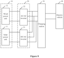
Figure 8 is a schematic diagram illustrating the renewable energy charging system according to another embodiment of the present disclosure. - The technical solutions in the embodiments of the present disclosure are clearly and thoroughly described below in conjunction with the drawings in the embodiments of the present disclosure, so that the purpose, technical solutions and advantages of the embodiments of the present disclosure are comprehensible. It is apparent that the described embodiments are some rather than all of the embodiments of the present disclosure. Based on the embodiments of the present disclosure, all other embodiments obtained by those ordinary skilled in the art without creative efforts belong to the protection scope of the present disclosure.
- In the present disclosure, the terms "include", "comprise" or any variant thereof are intended to be nonexclusive, such that a process, method, article or device including a series of elements includes not only those elements but also other elements which have not been listed definitely or an element(s) inherent in the process, method, article or device. Unless expressively limited otherwise, a process, method, article or device limited by "comprising/including a(n) ..." does not exclude existence of other identical elements in such process, method, article or device.
- A charging method applied to an alternating current charging station is provided according to embodiments of the present disclosure, to solve the problem that the existing alternating current charging station fails to be widely used due to the fact that the alternating current charging station operates independently, i.e., fails to acquire the photovoltaic power capacity in real time and therefore only slightly adapts or even fails to adapt its output power to the photovoltaic system in real time.
- The connection of the alternating current charging station is as follows. A first end of the alternating current charging station is connected to a renewable energy module through a power conversion unit, to receive power outputted by the renewable energy module. A charging gun in the alternating current charging station is configured to connect to an electric vehicle, to charge the electric vehicle.
- Referring to
Figure 1 , the charging method includes the following steps S101 to S104. - In S 101, an available input power of a system to which the alternating current charging station is connected is measured.
- As can be seen from the above description, the available input power may be the output power of the renewable energy module, the output power of the power conversion unit, or the power received by the alternating current charging station, depends on the practical situations, and all of which are within the protection scope of the present disclosure.
- In practice, the available input power is grid power or renewable energy power, depends on the practical situations, and all of which are within the protection scope of the present disclosure.
- In a case that the available input power is greater than or equal to a single-phase threshold and less than a three-phase threshold, step S102 is executed. In a case that the available input power is greater than or equal to the three-phase threshold,
step S 103 is executed. - In S102, the alternating current charging station is controlled to supply single-phase power to the electric vehicle through the charging gun of the alternating current charging station.
- The single-phase threshold is less than the three-phase threshold.
- The available input power, when greater than or equal to the single-phase threshold and less than the three-phase threshold, can supply the single-phase power rather than three-phase power. Therefore, the alternating current charging station supplies the single-phase power to the electric vehicle through its own charging gun.
- In practice, the single-phase threshold is a product of a single-phase voltage and a single-phase current.
- The single-phase current is constant, and the single-phase voltage is obtained by converting the input voltage of the alternating current charging station.
- In other words, the single-phase threshold is variable, and varies with the input voltage of the alternating current charging station.
- In practice, step S102 is detailed as follows. Relays on any two of three-phase cables and a neutral cable are closed. For example, all the relays on the neutral cable and an A-phase cable are closed.
- In S103, the alternating current charging station is controlled to supply three-phase power to the electric vehicle through its own charging gun.
- The available input power, when greater than or equal to the three-phase threshold, can supply the three-phase power. Therefore, the alternating current charging station supplies the three-phase power to the electric vehicle through its own charging gun.
- The alternating current charging station outputs relatively small power when supplying the single-phase power, and therefore charges the electric vehicle slowly. The alternating current charging station outputs relatively large power when supplying the three-phase power, and therefore charges the electric vehicle quickly.
- Furthermore, in practice, the three-phase threshold is a product of a three-phase voltage and a three-phase current.
- The three-phase current is constant, and the three-phase voltage is obtained by converting the input voltage of the alternating current charging station.
- In other words, the three-phase threshold is variable, and varies with the input voltage of the alternating current charging station.
- In practice, step S103 includes: closing all relays on the three-phase cables.
- It should be noted that, when the neutral cable is provided with relays, all the relays on the neutral cable are also closed.
- In the embodiments, the output power of the alternating current charging station is regulated by switching phases for charging, so that the output power of the alternating current charging station can adapt to the available input power, thereby achieving optimal energy efficiency and carbon balance.
- In addition, in a case that the available input power is less than the single-phase threshold, the method further includes the following step S104 after step S101.
- In S104, the alternating current charging station is controlled to be in a sleep mode instead of charge the electric vehicle.
- The available input power, when less than the single-phase threshold, is insufficient to charge the electric vehicle. Therefore, the alternating current charging station stops charging the electric vehicle and switches to the sleep mode.
- It should be noted that there is a minimum charging current for charging the electric vehicle. The alternating current charging station, when outputting a charging current less than the minimum charging current, fails to charge the electric vehicle. Generally, the minimum charging current is not less than 6A in order to reliably charge the electric vehicle. The nominal single-phase voltage is 230V and the nominal three-phase voltage is 400V to the European standard. Therefore, the minimum single-phase charging power is about 1.38kW, which is the single-phase threshold, and the minimum three-phase charging power is about 4.156kW, which is the three-phase threshold.
- It should be noted that the conventional three-phase alternating current charging station can charge the electric vehicle only when the available input power exceeds the three-phase threshold for the purpose of power point tracking. In comparison, the alternating current charging station in the present disclosure can charge the electric vehicle as long as the available input power is greater than the single-phase threshold, which is more environment friendly. The conventional single-phase alternating current charging station starts the charging when the available input power is greater than the single-phase threshold. However, the maximum power should not exceed 7.4kW. The conventional single-phase alternating current may fail to perform the power point tracking otherwise, resulting in low utilization of green electricity. The power of 7.4kW is specified in the standard, and the maximum single-phase current should not exceed 32A. In comparison, the alternating current charging station in the present disclosure can output a maximum current of 16A and a maximum power of 11kW, and therefore performs power point tracking over a larger range.
- In addition, the conventional alternating current charging station can output only three-phase or single-phase power. That is, the same charging station fails to output a voltage varying over time. The alternating current charging station in the embodiments can switch between the three-phase power and the single-phase power, improving the power utilization. Further, the alternating current charging station is applicable to a variety of application scenarios and thus has strong adaptability.
- In practice, the method further includes: adapting the output power of the charging gun to the available input power in real time while the alternating current charging station charges the electric vehicle through its own charging gun. That is, the alternating current charging station charges the electric vehicle with a variable current, so that the output power is adapted to the available input power, thereby further optimizing the power utilization.
- Specifically, when the available input power is greater than or equal to the single-phase threshold and less than the three-phase threshold, the alternating current charging station is controlled to supply the single-phase power to the electric vehicle through its own charging gun, and regulate its own output current in real time to regulate its own output power.
- When the available input power is greater than or equal to the three-phase threshold, the alternating current charging station is controlled to provide the three-phase power to the electric vehicle through its own charging gun, and regulate its own output current in real time to regulate its own output power.
- The output power of the alternating current charging station is regulated as follows. The duty cycle is controlled base on the PWM signal, and therefore the output current of the alternating current charging station is regulated. That is, the output current is regulated by controlling the duty cycle based on the PWM signal. In other words, a waveform of the PWM signal is adjusted to control the duty cycle, and then the output current is regulated. For example, the alternating current charging station calculates a current based on an actual output power and converts the current into the PWM signal. Then, the actual charging current supplied to the electric vehicle is regulated based on the duty cycle in the PWM signal. The PWM signal is converted from the current by PWM=I/0.6. 0.6 is specified in the standard IEC61851.
- In any of the above embodiments, after step S101, the method further includes: controlling the alternating current charging station to respond to a charging gun signal to perform a switch between the single-phase power and the three-phase power when a demand for the switch is detected during the charging. The charging gun signal may be related to a simulated plugging or unplugging operation, a software wake-up signal, an actual plugging or unplugging operation, which depends on the actual situations.
- In an embodiment, the demand for the switch is detected when it is detected that the available input power changes from the single-phase threshold to the three-phase threshold, or when it is detected that the available input power changes from the three-phase threshold to the single-phase threshold.
- The alternating current charging station responds to the charging gun signal to perform the switch as follows. In a case that the charging gun signal is a first signal, the alternating current charging station is connected to the electric vehicle. In a case that the charging gun signal is a second signal, the alternating current charging station is disconnected from the electric vehicle.
- For example, the charging gun signal is related to the simulated plugging or unplugging. The alternating current charging station automatically performs the simulated plugging operation by communicatively connecting the alternating current charging station to the electric vehicle. The alternating current charging station automatically performs the simulated unplugging operation by communicatively disconnecting the alternating current charging station from the electric vehicle.
- During the charging, the alternating current charging station automatically performs the simulated unplugging and plugging operations when the available input power changes from the single-phase threshold to the three-phase threshold or from the three-phase threshold to the single-phase threshold, in order to wake up the electric vehicle. That is because that the electric vehicle may malfunction due to the switch between the single-phase power and the three-phase power. Therefore, the alternating current charging station performs the unplugging operation to stop charging, and then performs the plugging operation to start charging, and therefore reliably charges the electric vehicle at optimal power.
- The alternating current charging station automatically performs the simulated unplugging operation by communicatively disconnecting the alternating current charging station from the electric vehicle, for example, disabling the CP (control pilot function), connection confirm function PP, and ground protection conductor PE in European Standard Power System, and disabling the CP, CC, and ground protection conductor PE in the National Standard Power System. The alternating current charging station automatically performs the simulated plugging operation by communicatively connecting the alternating current charging station to the electric vehicle, for example, enabling the CP, connection confirm function PP, and ground protection conductor PE in European Standard Power System, and enabling the CP, CC (connection confirm function), and protection ground conductor PE in the National Standard Power System.
- In any of the above embodiments, before step S101, the method further includes: determining whether the alternating current charging station is in a power point tracking mode.
- In the power point tracking mode, the output power of the alternating current charging station is adapted to the available input power.
- If it is determined that the alternating current charging station is in the power tracking mode, step S101 is executed.
- If it is determined that the alternating current charging station is not in the power tracking mode, the alternating current charging station is determined as being in a normal operation mode, and the alternating current charging station is controlled to directly output the maximum power.
- In other words, the alternating current charging station is capable of operating in various modes instead of a single mode, for example, the normal operation mode and the power point tracking mode. In the normal operation mode, the alternating current charging station directly outputs the maximum power. In the power point tracking mode, the alternating current charging station adapts the output power of the alternating current charging station to the available input power in real time, thereby achieving optimal energy efficiency and carbon balance.
- The charging method is applicable to the European Standard Power System, National Standard Power System or the like, and all of which are within the protection scope of the present disclosure.
- An alternating current charging station is provided according to another embodiment of the present disclosure. Referring to
Figure 3 , the alternating current chargingstation 30 includes ametering module 31, acontroller 33, and multiple relays (RL1, RL2, RL3 and RL4 as shown inFigure 3 ) and at least one charginggun 32. - An input end of the
metering module 31 serves as the input end of the alternating current chargingstation 30, and is connected to thepower conversion unit 20 to receive the power outputted by thepower conversion unit 20. - An output port of the charging
gun 32 serves as the output end of the alternating current chargingstation 30, and is configured to connect theelectric vehicle 40 to charge theelectric vehicle 40. - The charging
gun 32 is connected to themetering module 31 through three-phase cables and a neutral cable. The three-phase cables and the neutral cable each are provided with at least one relay. The three-phase cables are an A-phase cable, a B-phase cable and a C-phase cable. - All the relays are controlled by the
controller 33. Thecontroller 33 is communicatively connected to themetering module 31. - The metering module calculates the power received by the alternating current charging station, and transmits a calculation result to the controller.
- It should be noted that, as shown in
Figure 2 , the alternating current charging station may include nometering module 31. The neutral cable may also be omitted, i.e., the charginggun 32 is connected to themetering module 31 through only the three-phase cables. Alternatively, the charginggun 32 is connected to the input end of the alternating current chargingstation 30 through only the three-phase cables. Details about the alternating current chargingstation 30 are not repeated here and are within the protection scope of the present disclosure. - The
controller 33 is configured to perform the charging method. Details about the charging method can refer to the above embodiments, and thus are not repeated here and are within the protection scope of the present disclosure. - According to the above description, the switch between the single-phase power and the three-phase power is performed by turning on the relay on the corresponding cable. It should be noted that the neutral cable should be conductive throughout the charging by the alternating current charging
station 30 as specified in the standards. Therefore, throughout the charging by the alternating current chargingstation 30, all the relays on the neutral cable are constantly closed. Therefore, the switch between the single-phase power and the three-phase power is achieved by controlling the three-phase cables. For instance, when all the relays on the neutral cable are closed and all the relays on the A-phase cable are closed, the alternating current chargingstation 30 outputs the single-phase power. When all the relays on the neutral cable are closed, all the relays on the A-phase cable are closed, all the relays on the B-phase cable are closed, and all the relays on the C-phase cable are closed, the alternating current chargingstation 30 outputs the three-phase power. - When the measurement result indicates that the available input power is less than the single-phase threshold, the alternating current charging
station 30 is controlled to be in the sleep mode without charging. When the measurement result indicates that the available input power is greater than or equal to the single-phase threshold and less than the three-phase threshold, the alternating current chargingstation 30 is controlled to supply the single-phase power, and the output current is regulated in real time in order to regulate the output power. When the measurement result indicates that the available input power is greater than or equal to the three-phase threshold, the alternating current chargingstation 30 supplies the three-phase power, and the output current is regulated in real time in order to regulate the output power. - In other words, the alternating current charging
station 30 supplies the single-phase power as follows. All the relays (RL1 and RL2 as shown inFigure 3 ) on the A-phase cable and the neutral cable are closed. In this case, the output power of the alternating current chargingstation 30 is equal to P=Va*Ia. - The alternating current charging
station 30 supplies the three-phase power as follows. All the relays (RL1, RL2, RL3, RL4 as shown inFigure 3 ) on the three-phase cables and the neutral cable are closed. In this case, the output power of the alternating current chargingstation 30 is equal to P=Va*Ia+Vb*Ib+Vc*Ic. - Va is a voltage across the the A-phase cable. Ia is a current following through the A-phase cable. Vb is a voltage across is the B-phase cable. Ib is a current following through the B-phase cable. Vc is a voltage across the C-phase cable. Ic is a current following through the C-phase cable. P is the output power. L1' and L1 represent the A-phase cable. L2' and L2 represent the A-phase cable. L3 ' and L3 represent the C-phase cable. N ' and N represent the neutral cable.
- The
controller 33 is further configured to communicate with at least one of thepower conversion unit 20 and the charginggun 32. - The
controller 33 acquires the total power actually outputted by thepower conversion unit 20. Thecontroller 33 may further acquire the operating status of thepower conversion unit 20, etc., which is not described exhaustively and is within the protection scope of the present disclosure. - The
controller 33 may further send a PWM signal to the charginggun 32 to regulate the charging current, thereby regulating the output power of the alternating current chargingstation 30, which is not described exhaustively and is within the protection scope of the present disclosure. - Referring to
Figure 4 , the alternating current chargingstation 30 further includes a human-computer interaction module 34 communicating with thecontroller 33. The user inputs a corresponding control command through the human-computer interaction module 34, to control a charging duration, a start of charging, etc. Further, the status of the alternating current chargingstation 30, for example, the remaining charging duration, may also be acquired through the human-computer interaction module 34. Details about the operation and the principle of the human-computer interaction module 34 are not specifically limited herein and depend on the actual situations, which are within the protection scope of the present disclosure. - A renewable energy charging system is provided according to another embodiment of the present disclosure. Referring to
Figure 5 , the renewable energy charging system includes apower conversion unit 20, arenewable energy module 10 and an alternating current chargingstation 30. - The
renewable energy module 10 is connected to the alternating current chargingstation 30 through thepower conversion unit 20. - The
power conversion unit 20 or the alternating current chargingstation 30 is configured to perform the charging method according to any one of the above embodiments. Details about the charging method can refer to the above embodiments, and thus are not repeated here and are within the protection scope of the present disclosure. - In other words, the
power conversion unit 20 or the alternating current charging station performs the charging method. Illustrations below are provided in these two cases. - In a first case, the
power conversion unit 20 performs the charging method. The alternating current chargingstation 30 includes ametering module 21, multiple relays (RL1, RL2, RL3 and RL4 as shown inFigure 3 ) and at least one charginggun 32. - The input end of the
metering module 31 serves as the input end of the alternating current chargingstation 30. The output port of the charginggun 32 serves as the output end of the alternating current chargingstation 30. The charginggun 32 is connected to themetering module 31 through three-phase cables and a neutral cable. The three-phase cables and the neutral cable each are provided with at least one relay. - All the relays are controlled by a controller inside the
power conversion unit 20. - The alternating current charging station may include no
metering module 31, depending on actual applications. The neutral cable may also be omitted, i.e., the charginggun 32 is connected to themetering module 31 through only the three-phase cables. Alternatively, the charginggun 32 is connected to the input end of the alternating current chargingstation 30 through only the three-phase cables. Details about the alternating current chargingstation 30 are not repeated here and are within the protection scope of the present disclosure. - In practice, the alternating current charging
station 30 is integrated with thepower conversion unit 40. - In a second case, the alternating current charging
station 30 performs the charging method. Referring toFigure 3 , the alternating current chargingstation 30 includes ametering module 31, acontroller 33, multiple relays (RL1, RL2, RL3 and RL4 as shown inFigure 3 ) and at least one charginggun 32. - The input end of the
metering module 31 serves as the input end of the alternating current chargingstation 30, and is connected to thepower conversion unit 20 to receive the power outputted by thepower conversion unit 20. - The output port of the charging
gun 32 serves as the output end of the alternating current chargingstation 30, and is configured to connect theelectric vehicle 40 to charge theelectric vehicle 40. - The charging
gun 32 is connected to themetering module 31 through three-phase cables and a neutral cable. The three-phase cables and the neutral cable each are provided with at least one relay. The three-phase cables are an A-phase cable, a B-phase cable and a C-phase cable. - All the relays are controlled by the
controller 33. Thecontroller 33 is communicatively connected to themetering module 31. - The metering module calculates the power received by the alternating current charging station, and transmits a calculation result to the controller.
- The alternating current charging station may include no
metering module 31, depending on actual applications. The neutral cable may also be omitted, i.e., the charginggun 32 is connected to themetering module 31 through only the three-phase cables. Alternatively, the charginggun 32 is connected to the input end of the alternating current chargingstation 30 through only the three-phase cables. Details about the alternating current chargingstation 30 are not repeated here and are within the protection scope of the present disclosure. - In practice, the alternating current charging
station 30 is independently arranged in the charging system. - The alternating current charging
station 30 communicates with thepower conversion unit 20 in real time. - The alternating current charging
station 30 acquires the total output power of thepower conversion unit 20 or the operating status of thepower conversion unit 20 through the communication, which is not described exhaustively and is within the protection scope of the present disclosure. - The alternating current charging
station 30 communicates with thepower conversion unit 20 as defined in RS485 or the like, which is not described exhaustively and within the protection scope of the present disclosure. - The
renewable energy module 10 includes at least one of asolar power unit 11, awind power unit 12, an energy storage device (not shown), and a hydrogen energy unit (not shown). - As shown in
Figure 6 , therenewable energy module 10 is a photovoltaic system. As shown inFigure 7 , therenewable energy module 10 is a wind power system. As shown inFigure 8 , therenewable energy module 10 is a hybrid power system. - In a case that the
renewable energy module 10 includes thesolar power unit 11, thepower conversion unit 20 includes an alternating current to directcurrent inverter 21 connected to thesolar power unit 11. - In a case that the
renewable energy module 10 includes awind power unit 12, thepower conversion unit 20 includes an alternating current to alternatingcurrent converter 22 connected to thewind power unit 12. - The features described in the embodiments in this specification may be replaced or combined with each other. The same and similar parts of the various embodiments in this specification can be referred to each other, and each embodiment focuses on the differences from other embodiments. In particular, since the system or the system embodiment is basically similar to the method embodiment, the description thereof is relatively simple, and the related parts can refer to the part of the description of the method embodiment. The systems and system embodiments described above are merely illustrative. The units described as separate components may or may not be physically separated. The components shown as units may or may not be physical units, that is, may be located in the same place or distributed among multiple network elements. Part or all of the modules may be selected according to practical needs to achieve the purpose of the solution of the embodiments, which can be understood and implemented by those skilled in the art without creative efforts.
- It should be further noted that the units and algorithm steps of the examples described in conjunction with the embodiments disclosed herein may be implemented by electronic hardware, computer software or a combination of the two. In order to clearly illustrate the possible interchangeability of the hardware and software, details about the steps of each example have been generally described according to their functions in the above description. Whether these functions are implemented by hardware or software depends on the specific applications and design constraints of the technical solution. Those skilled in the art may use different methods to implement the described functions for each specific application, without departing from the scope of the present disclosure.
- Embodiments of the present disclosure are described above merely, such that those skilled in the art can implement or use the present disclosure. Those skilled in the art can make various modifications to these embodiments. The general principle defined herein may be applied to other embodiments without departing from the spirit or scope of the present disclosure. Hence, the present disclosure should be defined by the broadest scope consistent with the principle and novel features disclosed herein instead of limited to the embodiments illustrated herein.
Claims (21)
- A charging method applied to an alternating current charging station, comprising:measuring an available input power of a system where the alternating current charging station is arranged;controlling the alternating current charging station to supply single-phase power to an electric vehicle through a charging gun of the alternating current charging station when the measured available input power is greater than or equal to a single-phase threshold and less than a three-phase threshold, wherein the single-phase threshold is less than the three-phase threshold; andcontrolling the alternating current charging station to supply three-phase power to the electric vehicle through the charging gun when the measured available input power is greater than or equal to the three-phase threshold.
- The charging method according to claim 1, further comprising:
controlling the alternating current charging station to be in a sleep mode instead of charging the electric vehicle when the measured available input power is less than the single-phase threshold, after the measuring the available input power. - The charging method according to claim 1, further comprising:
adapting output power of the charging gun to the available input power in real time while charging the electric vehicle by the alternating current charging station through the charging gun. - The charging method according to claim 1, wherein
the available input power is grid power, or renewable energy power. - The charging method according to claim 1, whereinthe single-phase threshold is a product of a single-phase voltage and a single-phase current; andthe three-phase threshold is a product of a three-phase voltage and a three-phase current, wherein the single-phase current and the three-phase current are constant, and the single-phase voltage and the three-phase voltage each are obtained by converting an input voltage of the alternating current charging station.
- The charging method according to claim 1, whereinthe controlling the alternating current charging station to supply the single-phase power to the electric vehicle through the charging gun comprises: closing relays on two of three-phase cables and a neutral cable; andthe controlling the alternating current charging station to supply the three-phase power to the electric vehicle through the charging gun comprises: closing all relays on the three-phase cables.
- The charging method according to any one of claims 1 to 6, further comprising:
controlling the alternating current charging station to respond to a charging gun signal to perform a switch between the single-phase power and the three-phase power when a demand for the switch is detected during the charging, after the measuring the available input power. - The charging method according to claim 7, wherein the controlling the alternating current charging station to respond to the charging gun signal to perform the switch comprises:connecting the alternating current charging station to the electric vehicle in a case that the charging gun signal is a first signal; anddisconnecting the alternating current charging station from the electric vehicle in a case that the charging gun signal is a second signal.
- The charging method applied the alternating current charging station according to any one of claims 1 to 6, further comprising:
determining whether the alternating current charging station is in a power tracking mode before the measuring the available input power, wherein output power of the alternating current charging station is adapted to the available input power in the power tracking mode, and the available input power is measured when it is determined that the alternating current charging station is in the power tracking mode. - The charging method applied the alternating current charging station according to any one of claims 1 to 6, further comprising:
determining that the alternating current charging station is in a normal operation mode and controlling the alternating current charging station to directly output maximum power when it is determined that the alternating current charging station is not in a power tracking mode, after determining whether the alternating current charging station is in the power tracking mode. - An alternating current charging station, comprising:a controller, relays and at least one charging gun, whereinan output port of the charging gun serves as an output end of the alternating current charging station;an input end of the alternating current charging station is connected to the charging gun through three-phase cables;each of the three-phase cables is provided with at least one of the relays;a neutral cable in the alternating current charging station is provided with at least one of the relays;all the relays are controlled by the controller; andthe controller is configured to perform the charging method according to any one of claims 1 to 10.
- The alternating current charging station according to claim 11, wherein
the input end of the alternating current charging station is connected to the charging gun through the neutral cable, and the neutral cable is provided with at least one of the relays. - The alternating current charging station according to claim 11, further comprising:
a metering module, wherein the metering module is arranged between the relays and the input end of the alternating current charging station, and the controller is communicatively connected to the metering module. - The alternating current charging station according to claim 11, wherein
the controller is further configured to communicate with at least one of a power conversion unit in a system where the controller is arranged and the charging gun. - The alternating current charging station according to any one of claims 11 to 14, further comprising:
a human-computer interaction module configured to communicated with the controller. - A renewable energy charging system, comprising:a power conversion unit, a renewable energy module and an alternating current charging station, whereinthe renewable energy module is connected to the alternating current charging station through the power conversion unit; andthe power conversion unit or the alternating current charging station is configured to perform the charging method according to any one of claims 1 to 10.
- The renewable energy charging system according to claim 16, whereinthe alternating current charging station comprises relays and at least one charging gun, and whereinan input end of the alternating current charging station is connected to the charging gun through three-phase cables;each of the three-phase cables is provided with at least one relay; andan output port of the charging gun serves as an output end of the alternating current charging station.
- The renewable energy charging system according to claim 17, whereinall the relays are controlled by a controller inside the power conversion unit for the power conversion unit to perform the charging method; andthe alternating current charging station further comprises a controller for the alternating current charging station to perform the charging method, wherein all the relays are controlled by the controller of the alternating current charging station, and the controller of the alternating current charging station is communicatively connected to the metering module.
- The renewable energy charging system according to claim 18, wherein the alternating current charging station is integrated with the power conversion unit.
- The renewable energy charging system according to claim 18, whereinthe alternating current charging station is independently arranged in the renewable energy charging system; andthe controller of the alternating current charging station is configured to communicate with the controller inside the power conversion unit in real time.
- The renewable energy charging system according to any one of claims 16 to 20, wherein the renewable energy module comprises:
at least one of a solar power unit, a wind power unit, an energy storage device and a hydrogen energy unit.
Applications Claiming Priority (2)
| Application Number | Priority Date | Filing Date | Title |
|---|---|---|---|
| CN202110969436.1A CN113459859B (en) | 2021-08-23 | 2021-08-23 | A new energy charging system, AC charging pile and charging method |
| PCT/CN2022/106954 WO2023024774A1 (en) | 2021-08-23 | 2022-07-21 | New-energy charging system, and alternating-current charging pile and charging method therefof |
Publications (2)
| Publication Number | Publication Date |
|---|---|
| EP4393764A1 true EP4393764A1 (en) | 2024-07-03 |
| EP4393764A4 EP4393764A4 (en) | 2025-01-22 |
Family
ID=77867012
Family Applications (1)
| Application Number | Title | Priority Date | Filing Date |
|---|---|---|---|
| EP22860120.9A Pending EP4393764A4 (en) | 2021-08-23 | 2022-07-21 | NEW ENERGY CHARGING SYSTEM AND AC CHARGING PILE AND CHARGING METHOD THEREFOR |
Country Status (4)
| Country | Link |
|---|---|
| US (1) | US20250091466A1 (en) |
| EP (1) | EP4393764A4 (en) |
| CN (1) | CN113459859B (en) |
| WO (1) | WO2023024774A1 (en) |
Families Citing this family (7)
| Publication number | Priority date | Publication date | Assignee | Title |
|---|---|---|---|---|
| CN113459859B (en) * | 2021-08-23 | 2023-10-31 | 阳光电源股份有限公司 | A new energy charging system, AC charging pile and charging method |
| CN115366720B (en) * | 2022-08-10 | 2025-06-06 | 福建星云电子股份有限公司 | An AC charging pile and charging method compatible with three-phase electricity and single-phase electricity |
| US20240343147A1 (en) * | 2023-04-12 | 2024-10-17 | GM Global Technology Operations LLC | Detection and mitigation of charging signal oscillations during offboard charging event |
| CN116424139A (en) * | 2023-05-12 | 2023-07-14 | 阳光电源股份有限公司 | Charging pile and charging pile charging control method |
| CN116316861B (en) * | 2023-05-23 | 2023-09-19 | 广州疆海科技有限公司 | Inverter for photovoltaic energy storage system |
| CN117239789B (en) * | 2023-11-13 | 2024-03-22 | 万帮数字能源股份有限公司 | Pile group three-phase balance control method and device |
| CN118651097B (en) * | 2024-08-20 | 2024-12-06 | 深圳市丁旺科技有限公司 | Distributed charging pile and distributed charging system |
Family Cites Families (12)
| Publication number | Priority date | Publication date | Assignee | Title |
|---|---|---|---|---|
| WO2013111127A1 (en) * | 2012-01-26 | 2013-08-01 | Better Place GmbH | Charge spot device for charging electric vehicles |
| FR2993514B1 (en) * | 2012-07-20 | 2015-12-04 | Schneider Electric Ind Sas | METHOD AND DEVICE FOR DISTRIBUTING ELECTRICAL ENERGY |
| DK3184352T3 (en) * | 2015-12-22 | 2023-07-31 | Zaptec Ip As | SYSTEM AND METHOD FOR DYNAMIC PHASE LOAD DISTRIBUTION WHEN CHARGING ELECTRIC VEHICLES |
| CN106300396A (en) * | 2016-08-29 | 2017-01-04 | 华北电力大学(保定) | Realize charging electric vehicle switching device and the charging method of three-phrase burden balance |
| CN108616155B (en) * | 2018-05-11 | 2022-02-11 | 台达电子企业管理(上海)有限公司 | Charging method and charging device |
| DE102018209761A1 (en) * | 2018-06-18 | 2019-12-19 | Bayerische Motoren Werke Aktiengesellschaft | Method for configuring a charging system and charging system for charging the electrical energy store of a vehicle |
| CN208715002U (en) * | 2018-07-13 | 2019-04-09 | 深圳新恒业电气有限公司 | It is suitable for the alternating-current charging pile device of heterogeneous output |
| CN110474409A (en) * | 2019-09-02 | 2019-11-19 | 西安特锐德智能充电科技有限公司 | A kind of charge control method and charging equipment |
| DE102019134379A1 (en) * | 2019-12-13 | 2021-06-17 | Sma Solar Technology Ag | ELECTRIC VEHICLE CHARGER, POWER SUPPLY SYSTEM AND METHOD OF CHARGING AN ELECTRIC VEHICLE WITH A CHARGER |
| CN111391696A (en) * | 2020-04-16 | 2020-07-10 | 深圳威迈斯新能源股份有限公司 | Single-three phase compatible bidirectional charger control circuit with optimal capacitance value |
| CN213167764U (en) * | 2020-06-29 | 2021-05-11 | 宁波三星智能电气有限公司 | Alternating-current charging stake with awakening function |
| CN113459859B (en) * | 2021-08-23 | 2023-10-31 | 阳光电源股份有限公司 | A new energy charging system, AC charging pile and charging method |
-
2021
- 2021-08-23 CN CN202110969436.1A patent/CN113459859B/en active Active
-
2022
- 2022-07-21 EP EP22860120.9A patent/EP4393764A4/en active Pending
- 2022-07-21 WO PCT/CN2022/106954 patent/WO2023024774A1/en not_active Ceased
- 2022-07-21 US US18/562,274 patent/US20250091466A1/en active Pending
Also Published As
| Publication number | Publication date |
|---|---|
| US20250091466A1 (en) | 2025-03-20 |
| CN113459859A (en) | 2021-10-01 |
| WO2023024774A1 (en) | 2023-03-02 |
| CN113459859B (en) | 2023-10-31 |
| EP4393764A4 (en) | 2025-01-22 |
Similar Documents
| Publication | Publication Date | Title |
|---|---|---|
| EP4393764A1 (en) | New-energy charging system, and alternating-current charging pile and charging method therefof | |
| US11777311B2 (en) | Grid-tied variable frequency facility | |
| AU2020242485B2 (en) | EV charger with adaptable charging protocol | |
| CN102005817B (en) | Uninterruptible power supply device based on microgrid and dispatching control method thereof | |
| US9276410B2 (en) | Dual use photovoltaic system | |
| US9899871B2 (en) | Islanded operating system | |
| EP2738902A1 (en) | Power supply system, distribution device, and power control device | |
| US20250096594A1 (en) | Method and system to control multiple sources of energy using an uninterruptible power supply | |
| CN110999013A (en) | energy storage system | |
| CN104201755B (en) | Vehicle-mounted diesel generating system under a kind of DC distribution mode and energy management method thereof | |
| CN215322084U (en) | Energy storage type direct current charging pile | |
| EP3989380A2 (en) | A novel method to overcome electrical circuit voltage and current limitations | |
| CN112886626A (en) | Master-slave energy storage system of optical storage charging station and power tracking control method thereof | |
| US10886744B2 (en) | Power conversion system, power supply system and power conversion device | |
| EP4325691A1 (en) | Electric power conversion system and electric power conversion device | |
| CN220673401U (en) | Micro-grid system of solid oxide fuel cell | |
| CN114243822A (en) | Battery inter-cluster balance adjusting system | |
| CN209748263U (en) | Intelligent safe standby power supply system | |
| CN223651977U (en) | power system | |
| CN220342044U (en) | Energy storage control management system and energy storage container | |
| CN220421472U (en) | Direct current stores up fills system | |
| CN214314586U (en) | Photovoltaic power generation system | |
| EP4277079B1 (en) | Power supply control system and control method thereof | |
| CN113809729A (en) | BIPV reverse power protection method and device and photovoltaic building integrated system | |
| CN110289653A (en) | Charge control method of lithium battery and system |
Legal Events
| Date | Code | Title | Description |
|---|---|---|---|
| STAA | Information on the status of an ep patent application or granted ep patent |
Free format text: STATUS: THE INTERNATIONAL PUBLICATION HAS BEEN MADE |
|
| PUAI | Public reference made under article 153(3) epc to a published international application that has entered the european phase |
Free format text: ORIGINAL CODE: 0009012 |
|
| STAA | Information on the status of an ep patent application or granted ep patent |
Free format text: STATUS: REQUEST FOR EXAMINATION WAS MADE |
|
| 17P | Request for examination filed |
Effective date: 20231127 |
|
| AK | Designated contracting states |
Kind code of ref document: A1 Designated state(s): AL AT BE BG CH CY CZ DE DK EE ES FI FR GB GR HR HU IE IS IT LI LT LU LV MC MK MT NL NO PL PT RO RS SE SI SK SM TR |
|
| DAV | Request for validation of the european patent (deleted) | ||
| DAX | Request for extension of the european patent (deleted) | ||
| A4 | Supplementary search report drawn up and despatched |
Effective date: 20241219 |
|
| RIC1 | Information provided on ipc code assigned before grant |
Ipc: B60L 53/51 20190101ALI20241213BHEP Ipc: B60L 53/63 20190101ALI20241213BHEP Ipc: B60L 53/57 20190101ALI20241213BHEP Ipc: B60L 53/52 20190101ALI20241213BHEP Ipc: B60L 53/50 20190101ALI20241213BHEP Ipc: B60L 53/31 20190101ALI20241213BHEP Ipc: B60L 53/14 20190101ALI20241213BHEP Ipc: H02J 3/26 20060101ALI20241213BHEP Ipc: B60L 53/66 20190101ALI20241213BHEP Ipc: B60L 53/53 20190101ALI20241213BHEP Ipc: H02J 3/28 20060101ALI20241213BHEP Ipc: B60L 53/64 20190101ALI20241213BHEP Ipc: B60L 53/62 20190101AFI20241213BHEP |
|
| STAA | Information on the status of an ep patent application or granted ep patent |
Free format text: STATUS: EXAMINATION IS IN PROGRESS |
|
| 17Q | First examination report despatched |
Effective date: 20250721 |