EP4393746A2 - Device and method for guiding boarding/alighting of vehicle - Google Patents
Device and method for guiding boarding/alighting of vehicle Download PDFInfo
- Publication number
- EP4393746A2 EP4393746A2 EP23202309.3A EP23202309A EP4393746A2 EP 4393746 A2 EP4393746 A2 EP 4393746A2 EP 23202309 A EP23202309 A EP 23202309A EP 4393746 A2 EP4393746 A2 EP 4393746A2
- Authority
- EP
- European Patent Office
- Prior art keywords
- vehicle
- occupant
- sidewalk
- information
- entrance
- Prior art date
- Legal status (The legal status is an assumption and is not a legal conclusion. Google has not performed a legal analysis and makes no representation as to the accuracy of the status listed.)
- Granted
Links
Images




Classifications
-
- B—PERFORMING OPERATIONS; TRANSPORTING
- B60—VEHICLES IN GENERAL
- B60K—ARRANGEMENT OR MOUNTING OF PROPULSION UNITS OR OF TRANSMISSIONS IN VEHICLES; ARRANGEMENT OR MOUNTING OF PLURAL DIVERSE PRIME-MOVERS IN VEHICLES; AUXILIARY DRIVES FOR VEHICLES; INSTRUMENTATION OR DASHBOARDS FOR VEHICLES; ARRANGEMENTS IN CONNECTION WITH COOLING, AIR INTAKE, GAS EXHAUST OR FUEL SUPPLY OF PROPULSION UNITS IN VEHICLES
- B60K35/00—Instruments specially adapted for vehicles; Arrangement of instruments in or on vehicles
- B60K35/10—Input arrangements, i.e. from user to vehicle, associated with vehicle functions or specially adapted therefor
-
- B—PERFORMING OPERATIONS; TRANSPORTING
- B60—VEHICLES IN GENERAL
- B60Q—ARRANGEMENT OF SIGNALLING OR LIGHTING DEVICES, THE MOUNTING OR SUPPORTING THEREOF OR CIRCUITS THEREFOR, FOR VEHICLES IN GENERAL
- B60Q9/00—Arrangement or adaptation of signal devices not provided for in one of main groups B60Q1/00 - B60Q7/00, e.g. haptic signalling
-
- B—PERFORMING OPERATIONS; TRANSPORTING
- B60—VEHICLES IN GENERAL
- B60K—ARRANGEMENT OR MOUNTING OF PROPULSION UNITS OR OF TRANSMISSIONS IN VEHICLES; ARRANGEMENT OR MOUNTING OF PLURAL DIVERSE PRIME-MOVERS IN VEHICLES; AUXILIARY DRIVES FOR VEHICLES; INSTRUMENTATION OR DASHBOARDS FOR VEHICLES; ARRANGEMENTS IN CONNECTION WITH COOLING, AIR INTAKE, GAS EXHAUST OR FUEL SUPPLY OF PROPULSION UNITS IN VEHICLES
- B60K35/00—Instruments specially adapted for vehicles; Arrangement of instruments in or on vehicles
- B60K35/20—Output arrangements, i.e. from vehicle to user, associated with vehicle functions or specially adapted therefor
- B60K35/21—Output arrangements, i.e. from vehicle to user, associated with vehicle functions or specially adapted therefor using visual output, e.g. blinking lights or matrix displays
-
- B—PERFORMING OPERATIONS; TRANSPORTING
- B60—VEHICLES IN GENERAL
- B60K—ARRANGEMENT OR MOUNTING OF PROPULSION UNITS OR OF TRANSMISSIONS IN VEHICLES; ARRANGEMENT OR MOUNTING OF PLURAL DIVERSE PRIME-MOVERS IN VEHICLES; AUXILIARY DRIVES FOR VEHICLES; INSTRUMENTATION OR DASHBOARDS FOR VEHICLES; ARRANGEMENTS IN CONNECTION WITH COOLING, AIR INTAKE, GAS EXHAUST OR FUEL SUPPLY OF PROPULSION UNITS IN VEHICLES
- B60K35/00—Instruments specially adapted for vehicles; Arrangement of instruments in or on vehicles
- B60K35/20—Output arrangements, i.e. from vehicle to user, associated with vehicle functions or specially adapted therefor
- B60K35/21—Output arrangements, i.e. from vehicle to user, associated with vehicle functions or specially adapted therefor using visual output, e.g. blinking lights or matrix displays
- B60K35/22—Display screens
-
- B—PERFORMING OPERATIONS; TRANSPORTING
- B60—VEHICLES IN GENERAL
- B60K—ARRANGEMENT OR MOUNTING OF PROPULSION UNITS OR OF TRANSMISSIONS IN VEHICLES; ARRANGEMENT OR MOUNTING OF PLURAL DIVERSE PRIME-MOVERS IN VEHICLES; AUXILIARY DRIVES FOR VEHICLES; INSTRUMENTATION OR DASHBOARDS FOR VEHICLES; ARRANGEMENTS IN CONNECTION WITH COOLING, AIR INTAKE, GAS EXHAUST OR FUEL SUPPLY OF PROPULSION UNITS IN VEHICLES
- B60K35/00—Instruments specially adapted for vehicles; Arrangement of instruments in or on vehicles
- B60K35/20—Output arrangements, i.e. from vehicle to user, associated with vehicle functions or specially adapted therefor
- B60K35/28—Output arrangements, i.e. from vehicle to user, associated with vehicle functions or specially adapted therefor characterised by the type of the output information, e.g. video entertainment or vehicle dynamics information; characterised by the purpose of the output information, e.g. for attracting the attention of the driver
-
- B—PERFORMING OPERATIONS; TRANSPORTING
- B60—VEHICLES IN GENERAL
- B60N—SEATS SPECIALLY ADAPTED FOR VEHICLES; VEHICLE PASSENGER ACCOMMODATION NOT OTHERWISE PROVIDED FOR
- B60N5/00—Arrangements or devices on vehicles for entrance or exit control of passengers, e.g. turnstiles
-
- B—PERFORMING OPERATIONS; TRANSPORTING
- B60—VEHICLES IN GENERAL
- B60Q—ARRANGEMENT OF SIGNALLING OR LIGHTING DEVICES, THE MOUNTING OR SUPPORTING THEREOF OR CIRCUITS THEREFOR, FOR VEHICLES IN GENERAL
- B60Q5/00—Arrangement or adaptation of acoustic signal devices
- B60Q5/005—Arrangement or adaptation of acoustic signal devices automatically actuated
-
- B—PERFORMING OPERATIONS; TRANSPORTING
- B60—VEHICLES IN GENERAL
- B60W—CONJOINT CONTROL OF VEHICLE SUB-UNITS OF DIFFERENT TYPE OR DIFFERENT FUNCTION; CONTROL SYSTEMS SPECIALLY ADAPTED FOR HYBRID VEHICLES; ROAD VEHICLE DRIVE CONTROL SYSTEMS FOR PURPOSES NOT RELATED TO THE CONTROL OF A PARTICULAR SUB-UNIT
- B60W40/00—Estimation or calculation of non-directly measurable driving parameters for road vehicle drive control systems not related to the control of a particular sub unit, e.g. by using mathematical models
- B60W40/08—Estimation or calculation of non-directly measurable driving parameters for road vehicle drive control systems not related to the control of a particular sub unit, e.g. by using mathematical models related to drivers or passengers
-
- B—PERFORMING OPERATIONS; TRANSPORTING
- B60—VEHICLES IN GENERAL
- B60W—CONJOINT CONTROL OF VEHICLE SUB-UNITS OF DIFFERENT TYPE OR DIFFERENT FUNCTION; CONTROL SYSTEMS SPECIALLY ADAPTED FOR HYBRID VEHICLES; ROAD VEHICLE DRIVE CONTROL SYSTEMS FOR PURPOSES NOT RELATED TO THE CONTROL OF A PARTICULAR SUB-UNIT
- B60W60/00—Drive control systems specially adapted for autonomous road vehicles
- B60W60/001—Planning or execution of driving tasks
- B60W60/0025—Planning or execution of driving tasks specially adapted for specific operations
- B60W60/00253—Taxi operations
-
- B—PERFORMING OPERATIONS; TRANSPORTING
- B60—VEHICLES IN GENERAL
- B60K—ARRANGEMENT OR MOUNTING OF PROPULSION UNITS OR OF TRANSMISSIONS IN VEHICLES; ARRANGEMENT OR MOUNTING OF PLURAL DIVERSE PRIME-MOVERS IN VEHICLES; AUXILIARY DRIVES FOR VEHICLES; INSTRUMENTATION OR DASHBOARDS FOR VEHICLES; ARRANGEMENTS IN CONNECTION WITH COOLING, AIR INTAKE, GAS EXHAUST OR FUEL SUPPLY OF PROPULSION UNITS IN VEHICLES
- B60K2360/00—Indexing scheme associated with groups B60K35/00 or B60K37/00 relating to details of instruments or dashboards
- B60K2360/16—Type of output information
- B60K2360/165—Videos and animations
-
- B—PERFORMING OPERATIONS; TRANSPORTING
- B60—VEHICLES IN GENERAL
- B60K—ARRANGEMENT OR MOUNTING OF PROPULSION UNITS OR OF TRANSMISSIONS IN VEHICLES; ARRANGEMENT OR MOUNTING OF PLURAL DIVERSE PRIME-MOVERS IN VEHICLES; AUXILIARY DRIVES FOR VEHICLES; INSTRUMENTATION OR DASHBOARDS FOR VEHICLES; ARRANGEMENTS IN CONNECTION WITH COOLING, AIR INTAKE, GAS EXHAUST OR FUEL SUPPLY OF PROPULSION UNITS IN VEHICLES
- B60K2360/00—Indexing scheme associated with groups B60K35/00 or B60K37/00 relating to details of instruments or dashboards
- B60K2360/16—Type of output information
- B60K2360/171—Vehicle or relevant part thereof displayed
-
- B—PERFORMING OPERATIONS; TRANSPORTING
- B60—VEHICLES IN GENERAL
- B60K—ARRANGEMENT OR MOUNTING OF PROPULSION UNITS OR OF TRANSMISSIONS IN VEHICLES; ARRANGEMENT OR MOUNTING OF PLURAL DIVERSE PRIME-MOVERS IN VEHICLES; AUXILIARY DRIVES FOR VEHICLES; INSTRUMENTATION OR DASHBOARDS FOR VEHICLES; ARRANGEMENTS IN CONNECTION WITH COOLING, AIR INTAKE, GAS EXHAUST OR FUEL SUPPLY OF PROPULSION UNITS IN VEHICLES
- B60K2360/00—Indexing scheme associated with groups B60K35/00 or B60K37/00 relating to details of instruments or dashboards
- B60K2360/16—Type of output information
- B60K2360/175—Autonomous driving
-
- B—PERFORMING OPERATIONS; TRANSPORTING
- B60—VEHICLES IN GENERAL
- B60K—ARRANGEMENT OR MOUNTING OF PROPULSION UNITS OR OF TRANSMISSIONS IN VEHICLES; ARRANGEMENT OR MOUNTING OF PLURAL DIVERSE PRIME-MOVERS IN VEHICLES; AUXILIARY DRIVES FOR VEHICLES; INSTRUMENTATION OR DASHBOARDS FOR VEHICLES; ARRANGEMENTS IN CONNECTION WITH COOLING, AIR INTAKE, GAS EXHAUST OR FUEL SUPPLY OF PROPULSION UNITS IN VEHICLES
- B60K2360/00—Indexing scheme associated with groups B60K35/00 or B60K37/00 relating to details of instruments or dashboards
- B60K2360/16—Type of output information
- B60K2360/178—Warnings
-
- B—PERFORMING OPERATIONS; TRANSPORTING
- B60—VEHICLES IN GENERAL
- B60K—ARRANGEMENT OR MOUNTING OF PROPULSION UNITS OR OF TRANSMISSIONS IN VEHICLES; ARRANGEMENT OR MOUNTING OF PLURAL DIVERSE PRIME-MOVERS IN VEHICLES; AUXILIARY DRIVES FOR VEHICLES; INSTRUMENTATION OR DASHBOARDS FOR VEHICLES; ARRANGEMENTS IN CONNECTION WITH COOLING, AIR INTAKE, GAS EXHAUST OR FUEL SUPPLY OF PROPULSION UNITS IN VEHICLES
- B60K2360/00—Indexing scheme associated with groups B60K35/00 or B60K37/00 relating to details of instruments or dashboards
- B60K2360/16—Type of output information
- B60K2360/179—Distances to obstacles or vehicles
-
- B—PERFORMING OPERATIONS; TRANSPORTING
- B60—VEHICLES IN GENERAL
- B60K—ARRANGEMENT OR MOUNTING OF PROPULSION UNITS OR OF TRANSMISSIONS IN VEHICLES; ARRANGEMENT OR MOUNTING OF PLURAL DIVERSE PRIME-MOVERS IN VEHICLES; AUXILIARY DRIVES FOR VEHICLES; INSTRUMENTATION OR DASHBOARDS FOR VEHICLES; ARRANGEMENTS IN CONNECTION WITH COOLING, AIR INTAKE, GAS EXHAUST OR FUEL SUPPLY OF PROPULSION UNITS IN VEHICLES
- B60K2360/00—Indexing scheme associated with groups B60K35/00 or B60K37/00 relating to details of instruments or dashboards
- B60K2360/18—Information management
- B60K2360/186—Displaying information according to relevancy
-
- B—PERFORMING OPERATIONS; TRANSPORTING
- B60—VEHICLES IN GENERAL
- B60K—ARRANGEMENT OR MOUNTING OF PROPULSION UNITS OR OF TRANSMISSIONS IN VEHICLES; ARRANGEMENT OR MOUNTING OF PLURAL DIVERSE PRIME-MOVERS IN VEHICLES; AUXILIARY DRIVES FOR VEHICLES; INSTRUMENTATION OR DASHBOARDS FOR VEHICLES; ARRANGEMENTS IN CONNECTION WITH COOLING, AIR INTAKE, GAS EXHAUST OR FUEL SUPPLY OF PROPULSION UNITS IN VEHICLES
- B60K2360/00—Indexing scheme associated with groups B60K35/00 or B60K37/00 relating to details of instruments or dashboards
- B60K2360/18—Information management
- B60K2360/186—Displaying information according to relevancy
- B60K2360/1876—Displaying information according to relevancy according to vehicle situations
-
- B—PERFORMING OPERATIONS; TRANSPORTING
- B60—VEHICLES IN GENERAL
- B60K—ARRANGEMENT OR MOUNTING OF PROPULSION UNITS OR OF TRANSMISSIONS IN VEHICLES; ARRANGEMENT OR MOUNTING OF PLURAL DIVERSE PRIME-MOVERS IN VEHICLES; AUXILIARY DRIVES FOR VEHICLES; INSTRUMENTATION OR DASHBOARDS FOR VEHICLES; ARRANGEMENTS IN CONNECTION WITH COOLING, AIR INTAKE, GAS EXHAUST OR FUEL SUPPLY OF PROPULSION UNITS IN VEHICLES
- B60K2360/00—Indexing scheme associated with groups B60K35/00 or B60K37/00 relating to details of instruments or dashboards
- B60K2360/20—Optical features of instruments
- B60K2360/21—Optical features of instruments using cameras
-
- B—PERFORMING OPERATIONS; TRANSPORTING
- B60—VEHICLES IN GENERAL
- B60K—ARRANGEMENT OR MOUNTING OF PROPULSION UNITS OR OF TRANSMISSIONS IN VEHICLES; ARRANGEMENT OR MOUNTING OF PLURAL DIVERSE PRIME-MOVERS IN VEHICLES; AUXILIARY DRIVES FOR VEHICLES; INSTRUMENTATION OR DASHBOARDS FOR VEHICLES; ARRANGEMENTS IN CONNECTION WITH COOLING, AIR INTAKE, GAS EXHAUST OR FUEL SUPPLY OF PROPULSION UNITS IN VEHICLES
- B60K35/00—Instruments specially adapted for vehicles; Arrangement of instruments in or on vehicles
- B60K35/20—Output arrangements, i.e. from vehicle to user, associated with vehicle functions or specially adapted therefor
- B60K35/25—Output arrangements, i.e. from vehicle to user, associated with vehicle functions or specially adapted therefor using haptic output
-
- B—PERFORMING OPERATIONS; TRANSPORTING
- B60—VEHICLES IN GENERAL
- B60K—ARRANGEMENT OR MOUNTING OF PROPULSION UNITS OR OF TRANSMISSIONS IN VEHICLES; ARRANGEMENT OR MOUNTING OF PLURAL DIVERSE PRIME-MOVERS IN VEHICLES; AUXILIARY DRIVES FOR VEHICLES; INSTRUMENTATION OR DASHBOARDS FOR VEHICLES; ARRANGEMENTS IN CONNECTION WITH COOLING, AIR INTAKE, GAS EXHAUST OR FUEL SUPPLY OF PROPULSION UNITS IN VEHICLES
- B60K35/00—Instruments specially adapted for vehicles; Arrangement of instruments in or on vehicles
- B60K35/20—Output arrangements, i.e. from vehicle to user, associated with vehicle functions or specially adapted therefor
- B60K35/26—Output arrangements, i.e. from vehicle to user, associated with vehicle functions or specially adapted therefor using acoustic output
-
- B—PERFORMING OPERATIONS; TRANSPORTING
- B60—VEHICLES IN GENERAL
- B60K—ARRANGEMENT OR MOUNTING OF PROPULSION UNITS OR OF TRANSMISSIONS IN VEHICLES; ARRANGEMENT OR MOUNTING OF PLURAL DIVERSE PRIME-MOVERS IN VEHICLES; AUXILIARY DRIVES FOR VEHICLES; INSTRUMENTATION OR DASHBOARDS FOR VEHICLES; ARRANGEMENTS IN CONNECTION WITH COOLING, AIR INTAKE, GAS EXHAUST OR FUEL SUPPLY OF PROPULSION UNITS IN VEHICLES
- B60K35/00—Instruments specially adapted for vehicles; Arrangement of instruments in or on vehicles
- B60K35/20—Output arrangements, i.e. from vehicle to user, associated with vehicle functions or specially adapted therefor
- B60K35/26—Output arrangements, i.e. from vehicle to user, associated with vehicle functions or specially adapted therefor using acoustic output
- B60K35/265—Voice
-
- B—PERFORMING OPERATIONS; TRANSPORTING
- B60—VEHICLES IN GENERAL
- B60Q—ARRANGEMENT OF SIGNALLING OR LIGHTING DEVICES, THE MOUNTING OR SUPPORTING THEREOF OR CIRCUITS THEREFOR, FOR VEHICLES IN GENERAL
- B60Q2800/00—Features related to particular types of vehicles not otherwise provided for
- B60Q2800/10—Autonomous vehicles
-
- B—PERFORMING OPERATIONS; TRANSPORTING
- B60—VEHICLES IN GENERAL
- B60W—CONJOINT CONTROL OF VEHICLE SUB-UNITS OF DIFFERENT TYPE OR DIFFERENT FUNCTION; CONTROL SYSTEMS SPECIALLY ADAPTED FOR HYBRID VEHICLES; ROAD VEHICLE DRIVE CONTROL SYSTEMS FOR PURPOSES NOT RELATED TO THE CONTROL OF A PARTICULAR SUB-UNIT
- B60W2420/00—Indexing codes relating to the type of sensors based on the principle of their operation
- B60W2420/40—Photo, light or radio wave sensitive means, e.g. infrared sensors
- B60W2420/403—Image sensing, e.g. optical camera
-
- B—PERFORMING OPERATIONS; TRANSPORTING
- B60—VEHICLES IN GENERAL
- B60W—CONJOINT CONTROL OF VEHICLE SUB-UNITS OF DIFFERENT TYPE OR DIFFERENT FUNCTION; CONTROL SYSTEMS SPECIALLY ADAPTED FOR HYBRID VEHICLES; ROAD VEHICLE DRIVE CONTROL SYSTEMS FOR PURPOSES NOT RELATED TO THE CONTROL OF A PARTICULAR SUB-UNIT
- B60W2420/00—Indexing codes relating to the type of sensors based on the principle of their operation
- B60W2420/40—Photo, light or radio wave sensitive means, e.g. infrared sensors
- B60W2420/408—Radar; Laser, e.g. lidar
-
- B—PERFORMING OPERATIONS; TRANSPORTING
- B60—VEHICLES IN GENERAL
- B60W—CONJOINT CONTROL OF VEHICLE SUB-UNITS OF DIFFERENT TYPE OR DIFFERENT FUNCTION; CONTROL SYSTEMS SPECIALLY ADAPTED FOR HYBRID VEHICLES; ROAD VEHICLE DRIVE CONTROL SYSTEMS FOR PURPOSES NOT RELATED TO THE CONTROL OF A PARTICULAR SUB-UNIT
- B60W2540/00—Input parameters relating to occupants
-
- B—PERFORMING OPERATIONS; TRANSPORTING
- B60—VEHICLES IN GENERAL
- B60W—CONJOINT CONTROL OF VEHICLE SUB-UNITS OF DIFFERENT TYPE OR DIFFERENT FUNCTION; CONTROL SYSTEMS SPECIALLY ADAPTED FOR HYBRID VEHICLES; ROAD VEHICLE DRIVE CONTROL SYSTEMS FOR PURPOSES NOT RELATED TO THE CONTROL OF A PARTICULAR SUB-UNIT
- B60W2552/00—Input parameters relating to infrastructure
- B60W2552/45—Pedestrian sidewalk
-
- G—PHYSICS
- G09—EDUCATION; CRYPTOGRAPHY; DISPLAY; ADVERTISING; SEALS
- G09B—EDUCATIONAL OR DEMONSTRATION APPLIANCES; APPLIANCES FOR TEACHING, OR COMMUNICATING WITH, THE BLIND, DEAF OR MUTE; MODELS; PLANETARIA; GLOBES; MAPS; DIAGRAMS
- G09B21/00—Teaching, or communicating with, the blind, deaf or mute
- G09B21/001—Teaching or communicating with blind persons
- G09B21/006—Teaching or communicating with blind persons using audible presentation of the information
Definitions
- Level 0 (No Automation) is a step in which a driver controls and is responsible for everything in driving. The driver always drives, and a system of an autonomous vehicle performs only auxiliary functions such as emergency notification, etc. At this level, a subject of driving control is human and variable detection and driving responsibility during driving are held by the human.
- Level 4 is capable of autonomous driving on most roads. Both driving control and driving responsibility are held by a system. Driver intervention is unnecessary on most roads except for restricted situations. However, since driver intervention may be requested under certain conditions such as bad weather, a driving control device through humans is necessary for this level.
- Level 5 is a step of enabling a driving by an occupant only without a driver. The occupant enters only a destination and a system is responsible for driving under all conditions. At Level 5, control devices for steering, acceleration, and deceleration of an autonomous vehicle are unnecessary.
- one embodiment of the present disclosure is to provide a vehicle boarding/alighting guiding device that provides relative information by analyzing skeleton information of an occupant when visually impaired people board a vehicle, and provides wind when the occupant's body approaches the vehicle.
- the collecting, by the vehicle, of the body information of the occupant who is the transportation vulnerable may include collecting at least one of knee vertical level information and shoulder width information of the occupant via skeleton information.
- the determining of the arrival location of the vehicle based on the location of the occupant may include determining whether there is a sidewalk at the arrival location of the vehicle.
- the method may further include measuring a gap between the vehicle and the sidewalk when there is the sidewalk at the arrival location of the vehicle, and determining whether the measured gap between the vehicle and the sidewalk is equal to or smaller than a predetermined distance.
- the method may further include determining that the occupant is boarding/alighting the vehicle from/onto the sidewalk when the gap between the vehicle and the sidewalk is equal to or smaller than the predetermined distance.
- the method may further include determining that the occupant is boarding/alighting the vehicle from/onto a road surface when the gap between the vehicle and the sidewalk is not equal to or smaller than the predetermined distance.
- the providing of the relative information as the notification based on the body information of the occupant may include providing a guide notification based on a vertical level of the entrance of the vehicle when the occupant boards/alights the vehicle from/onto the road surface.
- the guide when the transportation vulnerable, especially the visually impaired people, board the vehicle, the guide may be provided for them to safely board/alight the vehicle without colliding with the vehicle.
- an autonomous driving control system e.g., an autonomous driving vehicle
- an autonomous driving apparatus e.g., an autonomous driving vehicle
- an autonomous driving vehicle 1000 may be implemented based on an autonomous driving integrated controller 600 that transmits and receives data necessary for autonomous driving control of a vehicle through a driving information input interface 101, a traveling information input interface 201, an occupant output interface 301, and a vehicle control output interface 401.
- the autonomous driving integrated controller 600 may also be referred to herein as a controller, a processor, or, simply, a controller.
- the control panel 120 may be implemented as a touchscreen panel that provides a user interface (UI) through which the occupant inputs or modifies information for autonomous driving control of the vehicle.
- UI user interface
- the driving mode switch 110 may be implemented as touch buttons on the control panel 120.
- the autonomous driving integrated controller 600 may transmit driving state information provided to the occupant to an output unit 300 through the occupant output interface 301 in the autonomous driving mode or manual driving mode of the vehicle. That is, the autonomous driving integrated controller 600 transmits the driving state information of the vehicle to the output unit 300 so that the occupant may check the autonomous driving state or manual driving state of the vehicle based on the driving state information output through the output unit 300.
- the driving state information may include various types of information indicative of driving states of the vehicle, such as a current driving mode, transmission range, and speed of the vehicle.
- the autonomous driving integrated controller 600 transmits warning information to the output unit 300 through the occupant output interface 301 so that the output unit 300 may output a warning to the driver.
- the output unit 300 may include a speaker 310 and a display 320 as illustrated in FIG. 1 .
- the display 320 may be implemented as the same device as the control panel 120 or may be implemented as an independent device separated from the control panel 120.
- the autonomous driving integrated controller 600 may transmit control information for driving control of the vehicle to a lower control system 400, applied to the vehicle, through the vehicle control output interface 401 in the autonomous driving mode or manual driving mode of the vehicle.
- the lower control system 400 for driving control of the vehicle may include an engine control system 410, a braking control system 420, and a steering control system 430.
- the autonomous driving integrated controller 600 may transmit engine control information, braking control information, and steering control information, as the control information, to the respective lower control systems 410, 420, and 430 through the vehicle control output interface 401.
- the engine control system 410 may control the speed and acceleration of the vehicle by increasing or decreasing fuel supplied to an engine.
- the braking control system 420 may control the braking of the vehicle by controlling braking power of the vehicle.
- the steering control system 430 may control the steering of the vehicle through a steering device (e.g., motor driven power steering (MDPS) system) applied to the vehicle.
- MDPS motor driven power steering
- the autonomous driving apparatus may include a sensor unit 500 for detecting a nearby object of the vehicle, such as a nearby vehicle, pedestrian, road, or fixed facility (e.g., a signal light, a signpost, a traffic sign, or a construction fence).
- a nearby object of the vehicle such as a nearby vehicle, pedestrian, road, or fixed facility (e.g., a signal light, a signpost, a traffic sign, or a construction fence).
- the LiDAR sensor 510 may transmit a laser signal to the periphery of the vehicle and detect a nearby object outside the vehicle by receiving a signal reflected and returning from a corresponding object.
- the LiDAR sensor 510 may detect a nearby object located within the ranges of a preset distance, a preset vertical field of view, and a preset horizontal field of view, which are predefined depending on specifications thereof.
- the LiDAR sensor 510 may include a front LiDAR sensor 511, a top LiDAR sensor 512, and a rear LiDAR sensor 513 installed at the front, top, and rear of the vehicle, respectively, but the installation location of each LiDAR sensor and the number of LiDAR sensors installed are not limited to a specific embodiment.
- an internal camera sensor 535 for capturing the inside of the vehicle may be mounted at a predetermined location (e.g., rear view mirror) within the vehicle.
- the autonomous driving integrated controller 600 may monitor a behavior and state of the occupant based on an image captured by the internal camera sensor 535 and output guidance or a warning to the occupant through the output unit 300.
- the sensor unit 500 may further include an ultrasonic sensor 540 in addition to the LiDAR sensor 510, the radar sensor 520, and the camera sensor 530 and further adopt various types of sensors for detecting a nearby object of the vehicle along with the sensors.
- the sensor unit 500 may further include a bio sensor for detecting bio signals (e.g., heart rate, electrocardiogram, respiration, blood pressure, body temperature, electroencephalogram, photoplethysmography (or pulse wave), and blood sugar) of the occupant.
- bio signals e.g., heart rate, electrocardiogram, respiration, blood pressure, body temperature, electroencephalogram, photoplethysmography (or pulse wave), and blood sugar
- the bio sensor may include a heart rate sensor, an electrocardiogram sensor, a respiration sensor, a blood pressure sensor, a body temperature sensor, an electroencephalogram sensor, a photoplethysmography sensor, and a blood sugar sensor.
- the sensor unit 500 additionally includes a microphone 550 having an internal microphone 551 and an external microphone 552 used for different purposes.
- the internal microphone 551 may be used, for example, to analyze the voice of the occupant in the autonomous driving vehicle 1000 based on AI or to immediately respond to a direct voice command of the occupant.
- the sensor unit 2100 is for recognizing an object around the vehicle 1000, and is able to include at least one of a camera sensor 2110, a vertical level measurement sensor 2120, and a proximity sensor 2130.
- the sensor unit 2100 may sense an occupant located around the vehicle.
- the camera sensor 2110 may capture an image of surroundings of the vehicle 1000 to detect the surrounding object outside the vehicle 1000, or may detect the surrounding object located within ranges of a set distance, a set vertical field of view, and a set horizontal field of view predefined based on a specification thereof.
- the camera sensor 2110 may include a front camera sensor, a left camera sensor, a right camera sensor, and a rear camera sensor installed on a front surface, a left side surface, a right side surface, and a rear surface of the vehicle 1000, respectively, but installation locations and the number of installed camera sensors are not limited by a particular embodiment.
- the processor 2400 of the vehicle 1000 may determine a location (including a distance to the corresponding object), a speed, a moving direction, and the like of the corresponding object by applying predefined image processing to the image captured via the camera sensor.
- the camera sensor 2110 may identify occupant skeleton information.
- the camera sensor 2110 may identify a location of the occupant.
- the lidar sensor may detect the surrounding object outside the vehicle 1000 by transmitting a laser signal to the location near the vehicle 1000 and receiving a signal reflected back by the corresponding object, or may detect the surrounding object located within ranges of a set distance, a set vertical field of view, and a set horizontal field of view predefined based on a specification thereof.
- the lidar sensor may include a front lidar sensor, a top lidar sensor, and a rear lidar sensor installed on the front surface, a top surface, and the rear surface of the vehicle 1000, respectively, but installation locations and the number of installed lidar sensors are not limited by a particular embodiment.
- the sensor unit 2100 may further include an ultrasonic sensor, and various types of sensors for detecting the object around the vehicle 1000 may be further employed for the sensor unit 2100.
- the communicator 2200 may include one or more transceivers, and may receive user data, control information, a wireless signal/channel, and the like referred to in functions, procedures, proposals, methods, and/or operational flowcharts disclosed herein from one or more other devices via the one or more transceivers.
- the one or more transceivers may be connected to the processor 2400 and may transmit and/or receive the wireless signal.
- at least one processor in the processor 2400 may control the one or more transceivers to transmit the user data, the control information, or the wireless signal to the one or more other devices.
- the processor 2400 may control the one or more transceivers to receive the user data, the control information, or the wireless signal from the one or more other devices.
- the one or more transceivers may be connected to one or more antennas, and the one or more transceivers may be set to transmit and/or receive the user data, the control information, the wireless signal/channel, and the like to and/or from other device(s) via the one or more antennas.
- the communicator 2200 may be connected to a remote device outside the vehicle via wireless communication and transmit boarding/alighting information.
- the communicator 2200 may be wirelessly connected to the remote device to provide a notification using the remote device instead of an external speaker.
- the outputter 2300 may include a wind discharger 2310 and a speaker 2320.
- Wind may be discharged continuously using the wind discharger 2310 to provide the close occupant within a certain distance from the vehicle with a notification.
- the speaker 2320 may be disposed at the upper end of the vehicle entrance to output a guide notification to the occupant.
- the processor 2400 may provide relative information as a notification based on the occupant body information.
- the processor 2400 may provide a guide notification based on a vertical level difference between the vehicle entrance and the sidewalk.
- the processor 2400 may provide wind when the body of the occupant approaches the entrance of the vehicle.
- the boarding/alighting guiding device 2000 may collect sidewalk vertical level information using the vertical level measurement sensor 2120.
- the boarding/alighting guiding device 2000 may provide the guide notification based on a vertical level difference between the vehicle entrance and the sidewalk 4000 because it is a situation in which the transportation vulnerable has to board the vehicle directly from the sidewalk.
- the boarding/alighting guiding device 2000 may provide a second guide notification when the occupant 3000 approaches the vehicle within 10 cm based on the relative vertical level of the occupant 3000.
- the third guide notification may be "The vehicle is flush with your knees. Lift your feet about 50 cm when boarding the vehicle.” or "The vehicle is flush with your knees. Lift your feet higher than usual when boarding the vehicle.”.
- the boarding/alighting guiding device 2000 may determine that the occupant 3000 needs to descend from the sidewalk 4000 to the road surface, and additionally provide the guide notification.
- the boarding/alighting guiding device 2000 may provide a fourth guide notification when it is necessary for the occupant 3000 to descend from the sidewalk to the road based on the vertical level of the vehicle entrance upon boarding.
- the vehicle may provide relative surroundings information compared with the body information of the occupant 3000.
- the boarding/alighting guiding device 2000 may provide alighting information based on the body information of the occupant 3000, including the vertical level difference between the vehicle and the road surface upon alighting, and a distance to the sidewalk 4000.
- the vehicle boarding/alighting guiding device 2000 may adjust the vehicle location based on the skeleton information 3100 of the occupant 3000 (S1030).
- the vehicle boarding/alighting guiding device 2000 may determine whether there is the sidewalk at the destination (S1120).
- step S1120 when there is no sidewalk at the destination (No in S1120), the vehicle boarding/alighting guiding device 2000 may determine that this is a situation in which the transportation vulnerable is boarding the vehicle from the road surface where the vehicle is located (S1125).
- the vehicle boarding/alighting guiding device 2000 may determine whether the gap between the vehicle entrance and the sidewalk 4000 is equal to or smaller than 10 cm (S1130).
- step S1130 when the gap between the vehicle entrance and the sidewalk 4000 is not equal to or smaller than 10 cm (No in S1130), the vehicle boarding/alighting guiding device 2000 may determine that this is a situation in which the transportation vulnerable is boarding the vehicle from the road surface where the vehicle is located (S1125).
- the technical idea of the present disclosure may be applied to an entirety of the autonomous vehicle or only to some components inside the autonomous vehicle.
- the scope of rights of the present disclosure should be determined based on the matters described in the claims.
Landscapes
- Engineering & Computer Science (AREA)
- Mechanical Engineering (AREA)
- Transportation (AREA)
- Chemical & Material Sciences (AREA)
- Combustion & Propulsion (AREA)
- Automation & Control Theory (AREA)
- Human Computer Interaction (AREA)
- Physics & Mathematics (AREA)
- Acoustics & Sound (AREA)
- Mathematical Physics (AREA)
- Traffic Control Systems (AREA)
Abstract
Description
- The present embodiments are applicable to autonomous vehicles (vehicles) in all fields, and more specifically, for example, are also applicable to a vehicle system that the transportation vulnerable, especially, visually impaired people board.
- Society of Automotive Engineers (SAE), an American automotive engineering society, subdivides autonomous driving levels into a total of six steps, for example, from level 0 to level 5, as follows.
- Level 0 (No Automation) is a step in which a driver controls and is responsible for everything in driving. The driver always drives, and a system of an autonomous vehicle performs only auxiliary functions such as emergency notification, etc. At this level, a subject of driving control is human and variable detection and driving responsibility during driving are held by the human.
- Level 1 (Driver Assistance) is a step of assisting a driver through adaptive cruise control and lane keeping functions. By activating a system, a driver is assisted by maintaining a speed of an autonomous vehicle, a vehicle-to-vehicle distance, and lanes. At this level, driving control subjects are a human and a system, and both the detection of variables that occur during driving and the driving responsibility are held by the humans.
- Level 2 (Partial Automation) is a step in which an autonomous vehicle and a human can control steering and acceleration/deceleration of the autonomous vehicle for a certain period of time within a specific condition. Auxiliary functions such as steering at a gentle curve and maintaining a distance from a car in front are available. However, at this level, the detection of variables during driving and the driving responsibility are held by the human, the driver should always monitor a driving situation, and the driver should intervene immediately in a situation where the system is not aware of it.
- Level 3 (Conditional Automation) is the level at which a system is in charge of driving in certain sections of conditions, such as highways, and at which a driver intervenes only in case of danger. The system is in charge of driving control and variable detection during driving, and unlike Level 2, the monitoring is not required. However, if it exceeds the requirements of the system, the system requests the immediate intervention of the driver.
- Level 4 (High Automation) is capable of autonomous driving on most roads. Both driving control and driving responsibility are held by a system. Driver intervention is unnecessary on most roads except for restricted situations. However, since driver intervention may be requested under certain conditions such as bad weather, a driving control device through humans is necessary for this level.
- Level 5 (Full Automation) is a step of enabling a driving by an occupant only without a driver. The occupant enters only a destination and a system is responsible for driving under all conditions. At Level 5, control devices for steering, acceleration, and deceleration of an autonomous vehicle are unnecessary.
- However, when the transportation vulnerable, especially visually impaired people, board the vehicle, the autonomous vehicle only provides whether a door is opened or closed. The autonomous vehicle has a function of audibly providing whether the door is opened or closed, but does not have a function of outputting a warning by comparing body information of the visually impaired people with vertical levels of a bumper and a roof of the vehicle, so that there is a problem of a collision of the transportation vulnerable during boarding.
- To solve the problem described above, one embodiment of the present disclosure is to provide a vehicle boarding/alighting guiding device that provides relative information by analyzing skeleton information of an occupant when visually impaired people board a vehicle, and provides wind when the occupant's body approaches the vehicle.
- The problems to be solved in the present disclosure are not limited to the technical problems mentioned above, and other technical problems not mentioned will be clearly understood by those skilled in the art to which the present disclosure belongs from the description below.
- One aspect of the present disclosure provides a method for guiding boarding/alighting of a vehicle including collecting body information of an occupant when the occupant approaches the vehicle, determining an arrival location of the vehicle based on a location of the occupant, and providing relative information as a notification based on the body information of the occupant.
- In one implementation of the present disclosure, the collecting, by the vehicle, of the body information of the occupant who is the transportation vulnerable may include collecting at least one of knee vertical level information and shoulder width information of the occupant via skeleton information.
- In one implementation of the present disclosure, the determining of the arrival location of the vehicle based on the location of the occupant may include determining whether there is a sidewalk at the arrival location of the vehicle.
- In one implementation of the present disclosure, the method may further include measuring a gap between the vehicle and the sidewalk when there is the sidewalk at the arrival location of the vehicle, and determining whether the measured gap between the vehicle and the sidewalk is equal to or smaller than a predetermined distance.
- In one implementation of the present disclosure, the method may further include determining that the occupant is boarding/alighting the vehicle from/onto the sidewalk when the gap between the vehicle and the sidewalk is equal to or smaller than the predetermined distance.
- In one implementation of the present disclosure, the providing of the relative information as the notification based on the body information of the occupant may include providing a guide notification based on a vertical level difference between an entrance of the vehicle and the sidewalk when the occupant boards/alights the vehicle from/onto the sidewalk.
- In one implementation of the present disclosure, the method may further include determining that the occupant is boarding/alighting the vehicle from/onto a road surface when the gap between the vehicle and the sidewalk is not equal to or smaller than the predetermined distance.
- In one implementation of the present disclosure, the providing of the relative information as the notification based on the body information of the occupant may include providing a guide notification based on a vertical level of the entrance of the vehicle when the occupant boards/alights the vehicle from/onto the road surface.
- In one implementation of the present disclosure, the method may further include providing wind when the occupant approaches an entrance of the vehicle.
- According to one of the embodiments of the present disclosure, when the transportation vulnerable, especially the visually impaired people, board the vehicle, the guide may be provided for them to safely board/alight the vehicle without colliding with the vehicle.
- The effects obtainable from the present disclosure are not limited to the effects mentioned above, and other effects not mentioned will be clearly understood by those skilled in the art from the description below.
-
-
FIG. 1 is an overall block diagram of an autonomous driving control system to which an autonomous driving apparatus according to any one of embodiments of the present disclosure is applicable. -
FIG. 2 is a diagram illustrating an example in which an autonomous driving apparatus according to any one of embodiments of the present disclosure is applied to a vehicle. -
FIGS. 3 to 4 are diagrams for illustrating a vehicle boarding/alighting guiding device according to one of embodiments of the present disclosure. -
FIGS. 5 to 8 are diagrams for illustrating an operation of the transportation vulnerable boarding a vehicle according to embodiments of the present disclosure. -
FIG. 9 is a diagram for illustrating an operation of the transportation vulnerable alighting a vehicle according to embodiments of the present disclosure. -
FIG. 10 is a flowchart illustrating a guide method upon boarding of a vehicle according to embodiments of the present disclosure. -
FIG. 11 is a flowchart illustrating a guide method considering whether there is a sidewalk upon guiding boarding/alighting of a vehicle according to embodiments of the present disclosure. - Hereinafter, embodiments of the present disclosure will be described in detail with reference to the accompanying drawings so that those skilled in the art to which the present disclosure pertains may easily implement the present disclosure. However, the present disclosure may be implemented in various different forms and is not limited to the embodiments described herein. In addition, in order to clearly describe this disclosure in drawings, parts unrelated to the description are omitted and similar reference numbers are given to similar parts throughout the specification.
- Throughout the specification, when a part "includes" a certain component, this means that it may further include other components, rather than excluding other components, unless otherwise stated.
-
FIG. 1 is an overall block diagram of an autonomous driving control system to which an autonomous driving apparatus according to any one of embodiments of the present disclosure is applicable.FIG. 2 is a diagram illustrating an example in which an autonomous driving apparatus according to any one of embodiments of the present disclosure is applied to a vehicle. - First, a structure and function of an autonomous driving control system (e.g., an autonomous driving vehicle) to which an autonomous driving apparatus according to the present embodiments is applicable will be described with reference to
FIGS. 1 and2 . - As illustrated in
FIG. 1 , anautonomous driving vehicle 1000 may be implemented based on an autonomous driving integratedcontroller 600 that transmits and receives data necessary for autonomous driving control of a vehicle through a drivinginformation input interface 101, a travelinginformation input interface 201, anoccupant output interface 301, and a vehiclecontrol output interface 401. However, the autonomous driving integratedcontroller 600 may also be referred to herein as a controller, a processor, or, simply, a controller. - The autonomous driving integrated
controller 600 may obtain, through the drivinginformation input interface 101, driving information based on manipulation of an occupant for auser input unit 100 in an autonomous driving mode or manual driving mode of a vehicle. As illustrated inFIG. 1 , theuser input unit 100 may include adriving mode switch 110 and a control panel 120 (e.g., a navigation terminal mounted on the vehicle or a smartphone or tablet computer owned by the occupant). Accordingly, driving information may include driving mode information and navigation information of a vehicle. - For example, a driving mode (i.e., an autonomous driving mode/manual driving mode or a sports mode/eco mode/safety mode/normal mode) of the vehicle determined by manipulation of the occupant for the
driving mode switch 110 may be transmitted to the autonomous driving integratedcontroller 600 through the drivinginformation input interface 101 as the driving information. - Furthermore, navigation information, such as the destination of the occupant input through the
control panel 120 and a path up to the destination (e.g., the shortest path or preference path, selected by the occupant, among candidate paths up to the destination), may be transmitted to the autonomous driving integratedcontroller 600 through the drivinginformation input interface 101 as the driving information.. - The
control panel 120 may be implemented as a touchscreen panel that provides a user interface (UI) through which the occupant inputs or modifies information for autonomous driving control of the vehicle. In this case, thedriving mode switch 110 may be implemented as touch buttons on thecontrol panel 120. - In addition, the autonomous driving integrated
controller 600 may obtain traveling information indicative of a driving state of the vehicle through the travelinginformation input interface 201. The traveling information may include a steering angle formed when the occupant manipulates a steering wheel, an accelerator pedal stroke or brake pedal stroke formed when the occupant depresses an accelerator pedal or brake pedal, and various types of information indicative of driving states and behaviors of the vehicle, such as a vehicle speed, acceleration, a yaw, a pitch, and a roll formed in the vehicle. The traveling information may be detected by a traveling information detection unit 200, including asteering angle sensor 210, an accelerator position sensor (APS)/pedal travel sensor (PTS) 220, avehicle speed sensor 230, anacceleration sensor 240, and a yaw/pitch/roll sensor 250, as illustrated inFIG. 1 . - Furthermore, the traveling information of the vehicle may include location information of the vehicle. The location information of the vehicle may be obtained through a global positioning system (GPS)
receiver 260 applied to the vehicle. Such traveling information may be transmitted to the autonomous drivingintegrated controller 600 through the travelinginformation input interface 201 and may be used to control the driving of the vehicle in the autonomous driving mode or manual driving mode of the vehicle. - The autonomous driving
integrated controller 600 may transmit driving state information provided to the occupant to anoutput unit 300 through theoccupant output interface 301 in the autonomous driving mode or manual driving mode of the vehicle. That is, the autonomous drivingintegrated controller 600 transmits the driving state information of the vehicle to theoutput unit 300 so that the occupant may check the autonomous driving state or manual driving state of the vehicle based on the driving state information output through theoutput unit 300. The driving state information may include various types of information indicative of driving states of the vehicle, such as a current driving mode, transmission range, and speed of the vehicle. - If it is determined that it is necessary to warn a driver in the autonomous driving mode or manual driving mode of the vehicle along with the above driving state information, the autonomous driving
integrated controller 600 transmits warning information to theoutput unit 300 through theoccupant output interface 301 so that theoutput unit 300 may output a warning to the driver. In order to output such driving state information and warning information acoustically and visually, theoutput unit 300 may include aspeaker 310 and adisplay 320 as illustrated inFIG. 1 . In this case, thedisplay 320 may be implemented as the same device as thecontrol panel 120 or may be implemented as an independent device separated from thecontrol panel 120. - Furthermore, the autonomous driving
integrated controller 600 may transmit control information for driving control of the vehicle to alower control system 400, applied to the vehicle, through the vehiclecontrol output interface 401 in the autonomous driving mode or manual driving mode of the vehicle. As illustrated inFIG. 1 , thelower control system 400 for driving control of the vehicle may include anengine control system 410, abraking control system 420, and asteering control system 430. The autonomous drivingintegrated controller 600 may transmit engine control information, braking control information, and steering control information, as the control information, to the respectivelower control systems control output interface 401. Accordingly, theengine control system 410 may control the speed and acceleration of the vehicle by increasing or decreasing fuel supplied to an engine. Thebraking control system 420 may control the braking of the vehicle by controlling braking power of the vehicle. Thesteering control system 430 may control the steering of the vehicle through a steering device (e.g., motor driven power steering (MDPS) system) applied to the vehicle. - As described above, the autonomous driving
integrated controller 600 according to the present embodiment may obtain the driving information based on manipulation of the driver and the traveling information indicative of the driving state of the vehicle through the drivinginformation input interface 101 and the travelinginformation input interface 201, respectively, and transmit the driving state information and the warning information, generated based on an autonomous driving algorithm, to theoutput unit 300 through theoccupant output interface 301. In addition, the autonomous drivingintegrated controller 600 may transmit the control information generated based on the autonomous driving algorithm to thelower control system 400 through the vehiclecontrol output interface 401 so that driving control of the vehicle is performed. - In order to guarantee stable autonomous driving of the vehicle, it is necessary to continuously monitor the driving state of the vehicle by accurately measuring a driving environment of the vehicle and to control driving based on the measured driving environment. To this end, as illustrated in
FIG. 1 , the autonomous driving apparatus according to the present embodiment may include asensor unit 500 for detecting a nearby object of the vehicle, such as a nearby vehicle, pedestrian, road, or fixed facility (e.g., a signal light, a signpost, a traffic sign, or a construction fence). - The
sensor unit 500 may include one or more of aLiDAR sensor 510, aradar sensor 520, or acamera sensor 530, in order to detect a nearby object outside the vehicle, as illustrated inFIG. 1 . - The
LiDAR sensor 510 may transmit a laser signal to the periphery of the vehicle and detect a nearby object outside the vehicle by receiving a signal reflected and returning from a corresponding object. TheLiDAR sensor 510 may detect a nearby object located within the ranges of a preset distance, a preset vertical field of view, and a preset horizontal field of view, which are predefined depending on specifications thereof. TheLiDAR sensor 510 may include afront LiDAR sensor 511, atop LiDAR sensor 512, and arear LiDAR sensor 513 installed at the front, top, and rear of the vehicle, respectively, but the installation location of each LiDAR sensor and the number of LiDAR sensors installed are not limited to a specific embodiment. A threshold for determining the validity of a laser signal reflected and returning from a corresponding object may be previously stored in a memory (not illustrated) of the autonomous drivingintegrated controller 600. The autonomous drivingintegrated controller 600 may determine a location (including a distance to a corresponding object), speed, and moving direction of the corresponding object using a method of measuring time taken for a laser signal, transmitted through theLiDAR sensor 510, to be reflected and returning from the corresponding object. - The
radar sensor 520 may radiate electromagnetic waves around the vehicle and detect a nearby object outside the vehicle by receiving a signal reflected and returning from a corresponding object. Theradar sensor 520 may detect a nearby object within the ranges of a preset distance, a preset vertical field of view, and a preset horizontal field of view, which are predefined depending on specifications thereof. Theradar sensor 520 may include afront radar sensor 521, aleft radar sensor 522, aright radar sensor 523, and arear radar sensor 524 installed at the front, left, right, and rear of the vehicle, respectively, but the installation location of each radar sensor and the number of radar sensors installed are not limited to a specific embodiment. The autonomous drivingintegrated controller 600 may determine a location (including a distance to a corresponding object), speed, and moving direction of the corresponding object using a method of analyzing power of electromagnetic waves transmitted and received through theradar sensor 520. - The
camera sensor 530 may detect a nearby object outside the vehicle by photographing the periphery of the vehicle and detect a nearby object within the ranges of a preset distance, a preset vertical field of view, and a preset horizontal field of view, which are predefined depending on specifications thereof. - The
camera sensor 530 may include afront camera sensor 531, aleft camera sensor 532, aright camera sensor 533, and arear camera sensor 534 installed at the front, left, right, and rear of the vehicle, respectively, but the installation location of each camera sensor and the number of camera sensors installed are not limited to a specific embodiment. The autonomous drivingintegrated controller 600 may determine a location (including a distance to a corresponding object), speed, and moving direction of the corresponding object by applying predefined image processing to an image captured by thecamera sensor 530. - In addition, an
internal camera sensor 535 for capturing the inside of the vehicle may be mounted at a predetermined location (e.g., rear view mirror) within the vehicle. The autonomous drivingintegrated controller 600 may monitor a behavior and state of the occupant based on an image captured by theinternal camera sensor 535 and output guidance or a warning to the occupant through theoutput unit 300. - As illustrated in
FIG. 1 , thesensor unit 500 may further include anultrasonic sensor 540 in addition to theLiDAR sensor 510, theradar sensor 520, and thecamera sensor 530 and further adopt various types of sensors for detecting a nearby object of the vehicle along with the sensors. -
FIG. 2 illustrates an example in which, in order to aid in understanding the present embodiment, thefront LiDAR sensor 511 or thefront radar sensor 521 is installed at the front of the vehicle, therear LiDAR sensor 513 or therear radar sensor 524 is installed at the rear of the vehicle, and thefront camera sensor 531, theleft camera sensor 532, theright camera sensor 533, and therear camera sensor 534 are installed at the front, left, right, and rear of the vehicle, respectively. However, as described above, the installation location of each sensor and the number of sensors installed are not limited to a specific embodiment. - Furthermore, in order to determine a state of the occupant within the vehicle, the
sensor unit 500 may further include a bio sensor for detecting bio signals (e.g., heart rate, electrocardiogram, respiration, blood pressure, body temperature, electroencephalogram, photoplethysmography (or pulse wave), and blood sugar) of the occupant. The bio sensor may include a heart rate sensor, an electrocardiogram sensor, a respiration sensor, a blood pressure sensor, a body temperature sensor, an electroencephalogram sensor, a photoplethysmography sensor, and a blood sugar sensor. - Finally, the
sensor unit 500 additionally includes amicrophone 550 having aninternal microphone 551 and anexternal microphone 552 used for different purposes. - The
internal microphone 551 may be used, for example, to analyze the voice of the occupant in theautonomous driving vehicle 1000 based on AI or to immediately respond to a direct voice command of the occupant. - In contrast, the
external microphone 552 may be used, for example, to appropriately respond to safe driving by analyzing various sounds generated from the outside of theautonomous driving vehicle 1000 using various analysis tools such as deep learning. - For reference, the symbols illustrated in
FIG. 2 may perform the same or similar functions as those illustrated inFIG. 1 .FIG. 2 illustrates in more detail a relative positional relationship of each component (based on the interior of the autonomous driving vehicle 1000) as compared withFIG. 1 . -
FIGS. 3 to 4 are diagrams for illustrating a vehicle boarding/alighting guiding device according to one of embodiments of the present disclosure. - Referring to
FIGS. 3 and4 , a vehicle boarding/alightingguiding device 2000 may include asensor unit 2100, acommunicator 2200, anoutputter 2300, and aprocessor 2400. - The
sensor unit 2100 is for recognizing an object around thevehicle 1000, and is able to include at least one of acamera sensor 2110, a verticallevel measurement sensor 2120, and aproximity sensor 2130. Thesensor unit 2100 may sense an occupant located around the vehicle. - The
camera sensors 2110 may be disposed at an upper end and a lower end of a peripheral area of an entrance of the vehicle. - The
camera sensor 2110 may capture an image of surroundings of thevehicle 1000 to detect the surrounding object outside thevehicle 1000, or may detect the surrounding object located within ranges of a set distance, a set vertical field of view, and a set horizontal field of view predefined based on a specification thereof. - The
camera sensor 2110 may include a front camera sensor, a left camera sensor, a right camera sensor, and a rear camera sensor installed on a front surface, a left side surface, a right side surface, and a rear surface of thevehicle 1000, respectively, but installation locations and the number of installed camera sensors are not limited by a particular embodiment. Theprocessor 2400 of thevehicle 1000 may determine a location (including a distance to the corresponding object), a speed, a moving direction, and the like of the corresponding object by applying predefined image processing to the image captured via the camera sensor. - The
camera sensor 2110 may identify occupant skeleton information. Thecamera sensor 2110 may identify a location of the occupant. - The vertical
level measurement sensor 2120 may be disposed at the upper end of the peripheral area of the vehicle entrance. The verticallevel measurement sensor 2120 may be disposed around thecamera sensor 2110 in a parallel manner. - The vertical
level measurement sensor 2120 may identify at least one of a vertical level of the vehicle entrance, a vertical level of a surrounding obstacle, and a vertical level of a sidewalk. The verticallevel measurement sensor 2120 may use at least one of a radar sensor and a lidar sensor. - The
proximity sensors 2130 may be disposed inwardly and outwardly of rims of the vehicle entrance. At least oneproximity sensor 2130 may be disposed on one surface of the rim. - The
proximity sensor 2130 may sense a degree of proximity of a body to the vehicle. Theproximity sensor 2130 may use at least one of the radar sensor and the lidar sensor. - The radar sensor may detect the surrounding object outside the
vehicle 1000 by radiating an electromagnetic wave to a location near thevehicle 1000 and receiving a signal reflected back by the corresponding object, or may detect the surrounding object located within ranges of a set distance, a set vertical field of view, and a set horizontal field of view predefined based on a specification thereof. The radar sensor may include a front radar sensor, a left radar sensor, a right radar sensor, and a rear radar sensor installed on the front surface, the left side surface, the right side surface, and the rear surface of thevehicle 1000, respectively, but installation locations and the number of installed radar sensors are not limited by a particular embodiment. Theprocessor 2400 of thevehicle 1000 may determine the location (including the distance to the corresponding object), the speed, and the direction of movement of the corresponding object in a scheme of analyzing power of the electromagnetic wave transmitted and received via the radar sensor. - The lidar sensor may detect the surrounding object outside the
vehicle 1000 by transmitting a laser signal to the location near thevehicle 1000 and receiving a signal reflected back by the corresponding object, or may detect the surrounding object located within ranges of a set distance, a set vertical field of view, and a set horizontal field of view predefined based on a specification thereof. The lidar sensor may include a front lidar sensor, a top lidar sensor, and a rear lidar sensor installed on the front surface, a top surface, and the rear surface of thevehicle 1000, respectively, but installation locations and the number of installed lidar sensors are not limited by a particular embodiment. A threshold value for determining validity of the laser signal reflected back by the corresponding object may be stored in advance in a memory (not shown) of theprocessor 2400 of thevehicle 1000, and theprocessor 2400 of thevehicle 1000 may determine the location (including the distance to the corresponding object), the speed, and the moving direction of the corresponding object in a scheme of measuring a time for the laser signal transmitted via the lidar sensor to be reflected back by the corresponding object. - In addition to the camera sensor, the radar sensor, and the lidar sensor, the
sensor unit 2100 may further include an ultrasonic sensor, and various types of sensors for detecting the object around thevehicle 1000 may be further employed for thesensor unit 2100. - The
communicator 2200 may include one or more transceivers, and may receive user data, control information, a wireless signal/channel, and the like referred to in functions, procedures, proposals, methods, and/or operational flowcharts disclosed herein from one or more other devices via the one or more transceivers. For example, the one or more transceivers may be connected to theprocessor 2400 and may transmit and/or receive the wireless signal. For example, at least one processor in theprocessor 2400 may control the one or more transceivers to transmit the user data, the control information, or the wireless signal to the one or more other devices. In addition, theprocessor 2400 may control the one or more transceivers to receive the user data, the control information, or the wireless signal from the one or more other devices. In addition, the one or more transceivers may be connected to one or more antennas, and the one or more transceivers may be set to transmit and/or receive the user data, the control information, the wireless signal/channel, and the like to and/or from other device(s) via the one or more antennas. - The
communicator 2200 may be connected to a remote device outside the vehicle via wireless communication and transmit boarding/alighting information. In addition, thecommunicator 2200 may be wirelessly connected to the remote device to provide a notification using the remote device instead of an external speaker. - The
outputter 2300 may include awind discharger 2310 and aspeaker 2320. - The
wind discharger 2310 may be disposed at the vehicle entrance in a form of rims to provide wind to the occupant. - Wind may be discharged continuously using the
wind discharger 2310 to provide the close occupant within a certain distance from the vehicle with a notification. - The
speaker 2320 may be disposed at the upper end of the vehicle entrance to output a guide notification to the occupant. - The
processor 2400 may collect occupant body information when the occupant approaches the vehicle. Theprocessor 2400 may collect at least one of knee vertical level and shoulder width information of the occupant from the skeleton information. - The
processor 2400 may determine an arrival location of the vehicle based on the location of the occupant. Theprocessor 2400 may determine whether there is the sidewalk at the arrival location of the vehicle. When there is the sidewalk at the arrival location of the vehicle, theprocessor 2400 may measure a gap between the vehicle entrance and the sidewalk. Theprocessor 2400 may determine whether the measured gap between the vehicle entrance and the sidewalk is equal to or smaller than a predetermined distance. Theprocessor 2400 may determine that the occupant boards/alights the vehicle at the sidewalk when the gap between the vehicle entrance and the sidewalk is equal to or smaller than the predetermined distance. - The
processor 2400 may provide relative information as a notification based on the occupant body information. When the occupant boards/alights the vehicle at the sidewalk, theprocessor 2400 may provide a guide notification based on a vertical level difference between the vehicle entrance and the sidewalk. - The
processor 2400 may provide wind when the body of the occupant approaches the entrance of the vehicle. -
FIGS. 5 to 8 are diagrams for illustrating an operation of the transportation vulnerable boarding a vehicle according to embodiments of the present disclosure. - Referring to
FIG. 5 , when the vehicle arrives at a destination and stops, the boarding/alighting guiding device 2000 may collectskeleton information 3100 of anoccupant 3000 using thecamera sensor 2110. - The
skeleton information 3100 may include at least one of knee vertical level and shoulder width information of theoccupant 3000. The knee vertical level information may include relative vertical level information between theoccupant 3000 and the vehicle entrance, and the shoulder width information may include vehicle boarding location adjustment information and relative width information with a door width. - The boarding/
alighting guiding device 2000 may collect sidewalk vertical level information using the verticallevel measurement sensor 2120. - Referring to
FIG. 6 , when the transportation vulnerable approaches the vehicle to board the vehicle, the boarding/alighting guiding device 2000 may correct theskeleton information 3100 via the vehicle camera sensor. The transportation vulnerable may be people who experience inconvenience when using transportation or walking on a road. For example, the transportation vulnerable may include the physically handicapped, pregnant women, infants, children and adolescents, and the elderly. The physically handicapped may include the visually impaired people, hearing impaired people, and the like. In addition, the transportation vulnerable may further include buggy pushers, wheelchair users, and the like, but may not be limited thereto. - The boarding/
alighting guiding device 2000 may identify the occupant location via the vehicle camera sensor and adjust the arrival location of the vehicle for theoccupant 3000 to board the vehicle. To this end, the boarding/alighting guiding device 2000 may determine whether asidewalk 4000 exists. The boarding/alighting guiding device 2000 may determinesidewalk information 4100 when there is thesidewalk 4000. Thesidewalk information 4100 may include a vehicle entrance vertical level and a sidewalk vertical level, and a gap between the vehicle entrance and thesidewalk 4000. That is, the boarding/alighting guiding device 2000 may calculate the vehicle entrance vertical level and the sidewalk vertical level and measure the gap between the vehicle entrance and thesidewalk 4000. - The boarding/
alighting guiding device 2000 may provide a guide notification corresponding to the measured gap between the vehicle entrance and thesidewalk 4000. - Referring to
FIG. 7 , when theoccupant 3000 standing on thesidewalk 4000 boards the vehicle, the boarding/alighting guiding device 2000 may provide the guide notification via thespeaker 2320. - When the gap between the vehicle entrance and the
sidewalk 4000 is equal to or smaller than 10 cm, the boarding/alighting guiding device 2000 may provide the guide notification based on a vertical level difference between the vehicle entrance and thesidewalk 4000 because it is a situation in which the transportation vulnerable has to board the vehicle directly from the sidewalk. - The boarding/
alighting guiding device 2000 may provide a relative vertical level based on the knee vertical level of theskeleton information 3100 of theoccupant 3000 as information. - The boarding/
alighting guiding device 2000 may provide a first guide notification when theoccupant 3000 approaches the vehicle within 50 cm based on the relative vertical level of theoccupant 3000. For example, the first guide notification may be "The gap between the vehicle entrance and the sidewalk is 20 cm. When you're boarding the vehicle directly from the sidewalk, board with caution.". - The boarding/
alighting guiding device 2000 may provide a second guide notification when theoccupant 3000 approaches the vehicle within 10 cm based on the relative vertical level of theoccupant 3000. - For example, the second guide notification may be "The vehicle is flush with your ankles. Lift your feet about 20 cm when boarding the vehicle." or "The vehicle is flush with your ankles. You may board the vehicle without lifting your feet higher than usual when boarding the vehicle.".
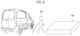
- Referring to
FIG. 8 , when theoccupant 3000 standing on a road surface boards the vehicle, the boarding/alighting guiding device 2000 may provide the guide notification. - Because this is the situation in which the
occupant 3000 has to board the vehicle from the road surface where the vehicle is located, the boarding/alighting guiding device 2000 may provide the guide notification considering only the vertical level of the vehicle entrance. - When the
occupant 3000 approached the vehicle within 10 cm based on the vertical level of the vehicle entrance when boarding the vehicle, the boarding/alighting guiding device 2000 may provide a third guide notification. - For example, the third guide notification may be "The vehicle is flush with your knees. Lift your feet about 50 cm when boarding the vehicle." or "The vehicle is flush with your knees. Lift your feet higher than usual when boarding the vehicle.".
- In one example, when the gap between the vehicle entrance and the
sidewalk 4000 exceeds 10 cm, the boarding/alighting guiding device 2000 may determine that theoccupant 3000 needs to descend from thesidewalk 4000 to the road surface, and additionally provide the guide notification. The boarding/alighting guiding device 2000 may provide a fourth guide notification when it is necessary for theoccupant 3000 to descend from the sidewalk to the road based on the vertical level of the vehicle entrance upon boarding. - For example, the fourth guide notification may be "A vertical level difference between the sidewalk and the road is 15 cm. Descend carefully."
-
FIG. 9 is a diagram for illustrating an operation of the transportation vulnerable alighting a vehicle according to embodiments of the present disclosure. - Referring to
FIG. 9 , when the vehicle arrives at the destination and theoccupant 3000 alights the vehicle, the vehicle may provide relative surroundings information compared with the body information of theoccupant 3000. - When arriving at the destination, the boarding/
alighting guiding device 2000 may identify theinformation 4100 of the surrounding sidewalk via the camera sensor. That is, the boarding/alighting guiding device 2000 may identify the gap between the vehicle entrance and thesidewalk 4000 and vertical level information of thesidewalk 4000. - When the
occupant 3000 alights the vehicle onto the road surface where the vehicle is located, the boarding/alighting guiding device 2000 may provide alighting information by comparing the vertical level of the vehicle and the body information based on theskeleton information 3100 of theoccupant 3000 upon alighting. - When the
occupant 3000 alights the vehicle onto thesidewalk 4000, the boarding/alighting guiding device 2000 may provide alighting information based on the body information of theoccupant 3000, including the vertical level difference between the vehicle and the road surface upon alighting, and a distance to thesidewalk 4000. - Thereafter, the boarding/
alighting guiding device 2000 may sense approach of theoccupant 3000 as theproximity sensor 2130 at the rim of the entrance operates when theoccupant 3000 alights the vehicle. - The boarding/
alighting guiding device 2000 may providewind 5000 such that the occupant's body (a head, legs, and torso) does not collide. The boarding/alighting guiding device 2000 may discharge thewind 5000 by increasing an intensity thereof as the body of theoccupant 3000 approaches the entrance rim. -
FIG. 10 is a flowchart illustrating a guide method upon boarding of a vehicle according to embodiments of the present disclosure. - Referring to
FIG. 10 , when the vehicle arrives at the destination (S1010), the vehicle boarding/alightingguiding device 2000 according to the present disclosure may collect theskeleton information 3100 of the occupant 3000 (S1020). - After step S1020, the vehicle boarding/alighting
guiding device 2000 may adjust the vehicle location based on theskeleton information 3100 of the occupant 3000 (S1030). - After step S1030, when the vehicle door is opened (S1040), the vehicle boarding/alighting
guiding device 2000 may provide relative information based on the occupant body information as a notification (S1050). - After step S1050, the vehicle boarding/alighting
guiding device 2000 may provide wind intensities based on the distance between the body of theoccupant 3000 and the entrance in a stepwise manner (S1060). -
FIG. 11 is a flowchart illustrating a guide method considering whether there is a sidewalk upon guiding boarding/alighting of a vehicle according to embodiments of the present disclosure. - Referring to
FIG. 11 , when the vehicle arrives at the destination (S1110), the vehicle boarding/alightingguiding device 2000 may determine whether there is the sidewalk at the destination (S1120). - After step S1120, when there is no sidewalk at the destination (No in S1120), the vehicle boarding/alighting
guiding device 2000 may determine that this is a situation in which the transportation vulnerable is boarding the vehicle from the road surface where the vehicle is located (S1125). - On the other hand, after step S1120, when there is the sidewalk at the destination (YES in S1120), the vehicle boarding/alighting
guiding device 2000 may determine whether the gap between the vehicle entrance and thesidewalk 4000 is equal to or smaller than 10 cm (S1130). - After step S1130, when the gap between the vehicle entrance and the
sidewalk 4000 is not equal to or smaller than 10 cm (No in S1130), the vehicle boarding/alightingguiding device 2000 may determine that this is a situation in which the transportation vulnerable is boarding the vehicle from the road surface where the vehicle is located (S1125). - On the other hand, after step S1130, when the gap between the vehicle entrance and the
sidewalk 4000 is equal to or smaller than 10 cm (No in S1130), the vehicle boarding/alightingguiding device 2000 may determine that this is a situation in which the transportation vulnerable is boarding the vehicle from the sidewalk (S1140). Thereafter, the vehicle boarding/alightingguiding device 2000 may provide the guide notification based on the vertical level difference between the vehicle and thesidewalk 4000. - That is, the technical idea of the present disclosure may be applied to an entirety of the autonomous vehicle or only to some components inside the autonomous vehicle. The scope of rights of the present disclosure should be determined based on the matters described in the claims.
- As another aspect of the present disclosure, the operation of the proposal or the invention described above may also be provided as a code that may be implemented, embodied, or executed by a "computer" (a comprehensive concept including a system on chip (SoC) or a microprocessor), an application storing or containing the code, a computer-readable storage medium, a computer program product, or the like, and this also falls within the scope of the present disclosure.
- The detailed descriptions of the preferred embodiments of the present disclosure disclosed as described above have been provided to enable those skilled in the art to implement and practice the present disclosure. Although the description has been made with reference to the preferred embodiments of the present disclosure, those skilled in the art will understand that the present disclosure may be variously modified and changed without departing from the scope of the present disclosure. For example, those skilled in the art may use the components described in the above-described embodiments in a scheme of combining the components with each other.
- Accordingly, the present disclosure is not intended to be limited to the embodiments illustrated herein, but is to be accorded the widest scope consistent with the principles and novel features disclosed herein.
Claims (15)
- A method for guiding boarding/alighting of a vehicle, the method comprising:collecting body information of an occupant;determining an arrival location of the vehicle based on a location of the occupant; andproviding relative information as a notification based on the body information of the occupant.
- The method of claim 1, wherein the collecting, by the vehicle, of the body information of the occupant includes:
collecting at least one of knee vertical level information and shoulder width information of the occupant via skeleton information included in the body information. - The method of claim 1 or 2, wherein the determining of the arrival location of the vehicle based on the location of the occupant includes:
determining whether there is a sidewalk at the arrival location of the vehicle. - The method of claim 3, further comprising:measuring a gap between an entrance of the vehicle and the sidewalk when there is the sidewalk at the arrival location of the vehicle; anddetermining whether the measured gap between the entrance of the vehicle and the sidewalk is equal to or smaller than a predetermined distance.
- The method of claim 4, further comprising:
determining that the occupant is to board/alight the vehicle from/onto the sidewalk when the gap between the entrance of the vehicle and the sidewalk is equal to or smaller than the predetermined distance. - The method of claim 4 or 5, wherein the providing of the relative information as the notification based on the body information of the occupant includes:
providing a guide notification based on a vertical level difference between the entrance of the vehicle and the sidewalk when determining that the occupant is to board/alight the vehicle from/onto the sidewalk. - The method of any one of claims 4 to 6, further comprising:
determining that the occupant is to board/alight the vehicle from/onto a road surface when the gap between the entrance of the vehicle and the sidewalk is greater than the predetermined distance. - The method of claim 7, wherein the providing of the relative information as the notification based on the body information of the occupant includes:
providing a guide notification based on a vertical level of the entrance of the vehicle when determining that the occupant is to board/alight the vehicle from/onto the road surface. - The method of any one of claims 1 to 8, further comprising:
providing wind when the occupant approaches an entrance of the vehicle. - A device for guiding boarding/alighting of a vehicle, the device comprising:an object detector configured to recognize an occupant outside the vehicle;a communicator configured to be in communication with a remote device;an outputter including a wind discharger and a speaker; anda processor configured to control at least one of the object detector, the communicator, and the outputter,wherein the processor is configured to:collect body information of the occupant;determine an arrival location of the vehicle based on a location of the occupant; andprovide relative information as a notification based on the body information of the occupant.
- The device of claim 10, wherein the processor is configured to collect at least one of knee vertical level information and shoulder width information of the occupant via skeleton information included in the body information.
- The device of claim 10 or 11, wherein the processor is configured to determine whether there is a sidewalk at the arrival location of the vehicle.
- The device of claim 12, wherein the processor is configured to:measure a gap between an entrance of the vehicle and the sidewalk when there is the sidewalk at the arrival location of the vehicle; anddetermine whether the measured gap between the entrance of the vehicle and the sidewalk is equal to or smaller than a predetermined distance.
- The device of claim 13, wherein the processor is configured to:determine that the occupant is to board/alight the vehicle from/onto the sidewalk when the gap between the entrance of the vehicle and the sidewalk is equal to or smaller than the predetermined distance,provide a guide notification based on a vertical level difference between the entrance of the vehicle and the sidewalk when determining that the occupant is to board/alight the vehicle from/onto the sidewalk.
- The device of claim 13 or 14, wherein the processor is configured to:determine that the occupant is to board/alight the vehicle from/onto a road surface when the gap between the entrance of the vehicle and the sidewalk is greater than the predetermined distance,provide a guide notification based on a vertical level of the entrance of the vehicle when determining that the occupant is to board/alight the vehicle from/onto the road surface.
Applications Claiming Priority (1)
| Application Number | Priority Date | Filing Date | Title |
|---|---|---|---|
| KR1020220169147A KR20240084367A (en) | 2022-12-06 | 2022-12-06 | Apparatus and method for guiding getting on and off the vehicle |
Publications (3)
| Publication Number | Publication Date |
|---|---|
| EP4393746A2 true EP4393746A2 (en) | 2024-07-03 |
| EP4393746A3 EP4393746A3 (en) | 2024-10-16 |
| EP4393746B1 EP4393746B1 (en) | 2025-12-31 |
Family
ID=88297289
Family Applications (1)
| Application Number | Title | Priority Date | Filing Date |
|---|---|---|---|
| EP23202309.3A Active EP4393746B1 (en) | 2022-12-06 | 2023-10-09 | DEVICE AND METHOD FOR GUARDING ENTRY AND EXIT FROM A VEHICLE |
Country Status (3)
| Country | Link |
|---|---|
| US (1) | US20240182076A1 (en) |
| EP (1) | EP4393746B1 (en) |
| KR (1) | KR20240084367A (en) |
Families Citing this family (2)
| Publication number | Priority date | Publication date | Assignee | Title |
|---|---|---|---|---|
| WO2021006354A1 (en) * | 2019-07-11 | 2021-01-14 | 京セラ株式会社 | Communication system, processing device, and personal possession |
| JP2025093067A (en) * | 2023-12-11 | 2025-06-23 | トヨタ自動車株式会社 | Ride assistance device, ride assistance method, and ride assistance computer program |
Family Cites Families (5)
| Publication number | Priority date | Publication date | Assignee | Title |
|---|---|---|---|---|
| FR3014571B1 (en) * | 2013-12-11 | 2021-04-09 | Dav | SENSORY FEEDBACK CONTROL DEVICE |
| DE102018212901A1 (en) * | 2018-08-02 | 2020-02-06 | Robert Bosch Gmbh | Method for determining a stopping position for an automated vehicle |
| US10989547B2 (en) * | 2018-10-22 | 2021-04-27 | Ford Global Technologies, Llc | Autonomous vehicle ride service systems and methods |
| US11488073B2 (en) * | 2019-06-28 | 2022-11-01 | Gm Cruise Holdings Llc | Autonomous vehicle rider drop-off to destination experience |
| CN114906050A (en) * | 2021-02-10 | 2022-08-16 | 奥迪股份公司 | System and method for guiding a vehicle occupant to board a vehicle |
-
2022
- 2022-12-06 KR KR1020220169147A patent/KR20240084367A/en active Pending
-
2023
- 2023-09-07 US US18/243,376 patent/US20240182076A1/en active Pending
- 2023-10-09 EP EP23202309.3A patent/EP4393746B1/en active Active
Also Published As
| Publication number | Publication date |
|---|---|
| US20240182076A1 (en) | 2024-06-06 |
| EP4393746A3 (en) | 2024-10-16 |
| KR20240084367A (en) | 2024-06-13 |
| EP4393746B1 (en) | 2025-12-31 |
Similar Documents
| Publication | Publication Date | Title |
|---|---|---|
| KR102184598B1 (en) | Driving Prediction and Safety Driving System Based on Judgment of Driver Emergency Situation of Autonomous Driving Vehicle | |
| US20200307632A1 (en) | Vehicle control system | |
| EP4393746A2 (en) | Device and method for guiding boarding/alighting of vehicle | |
| CN109983523A (en) | Driving change support device and drive change support method | |
| US12522247B2 (en) | Device and method for notifying vehicle arrival to respond to transportation vulnerable | |
| KR20230116122A (en) | Vehicle, Vehicle Collision-Avoidance system and Collision-Avoidance Method thereof | |
| US20240173179A1 (en) | Apparatus and method for guiding the transportation vulnerable | |
| KR20240081111A (en) | Apparatus and method for vehicle door handle guidance | |
| KR102568283B1 (en) | Pedestrian communication system for self driving cars | |
| KR20230172054A (en) | Vehicle collision-avoidance system and vehicle equipped with the system and collision-avoidance method thereof | |
| KR20240059809A (en) | Method and apparatus for voiding rear-danger driving vehicle | |
| KR20230114765A (en) | Safety supporting system for self driving cars | |
| KR20230114766A (en) | System for self driving cars | |
| US12337833B2 (en) | Method and apparatus for avoiding collision based on occupant position | |
| US20250091485A1 (en) | Exit assist function and seat device including the same | |
| EP4461597B1 (en) | Apparatus and method for controlling occupant customized seat | |
| EP4371542B1 (en) | Apparatus and method for providing convenience for the disabled using wheelchair | |
| US20250021177A1 (en) | Device and method for controlling mouse using gaze recognition | |
| KR102568288B1 (en) | Traffic safety system by communication with self driving cars | |
| KR102568270B1 (en) | Pedestrian communication system for self driving cars | |
| US20250340202A1 (en) | Automatic unparking apparatus and method | |
| KR20230159773A (en) | Vehicle collision-avoidance system and vehicle equipped with the system and collision-avoidance method thereof | |
| KR20230087671A (en) | Method and apparatus for preventing object collision | |
| KR20240081709A (en) | Apparatus and method for inducing the transportation vulnerable | |
| KR20230129076A (en) | Method and apparatus for preventing collision with overloaded vehicle |
Legal Events
| Date | Code | Title | Description |
|---|---|---|---|
| PUAI | Public reference made under article 153(3) epc to a published international application that has entered the european phase |
Free format text: ORIGINAL CODE: 0009012 |
|
| STAA | Information on the status of an ep patent application or granted ep patent |
Free format text: STATUS: THE APPLICATION HAS BEEN PUBLISHED |
|
| AK | Designated contracting states |
Kind code of ref document: A2 Designated state(s): AL AT BE BG CH CY CZ DE DK EE ES FI FR GB GR HR HU IE IS IT LI LT LU LV MC ME MK MT NL NO PL PT RO RS SE SI SK SM TR |
|
| PUAL | Search report despatched |
Free format text: ORIGINAL CODE: 0009013 |
|
| AK | Designated contracting states |
Kind code of ref document: A3 Designated state(s): AL AT BE BG CH CY CZ DE DK EE ES FI FR GB GR HR HU IE IS IT LI LT LU LV MC ME MK MT NL NO PL PT RO RS SE SI SK SM TR |
|
| RIC1 | Information provided on ipc code assigned before grant |
Ipc: B60K 35/28 20240101ALI20240910BHEP Ipc: B60K 35/22 20240101ALI20240910BHEP Ipc: B60K 35/10 20240101AFI20240910BHEP |
|
| STAA | Information on the status of an ep patent application or granted ep patent |
Free format text: STATUS: REQUEST FOR EXAMINATION WAS MADE |
|
| 17P | Request for examination filed |
Effective date: 20250415 |
|
| GRAP | Despatch of communication of intention to grant a patent |
Free format text: ORIGINAL CODE: EPIDOSNIGR1 |
|
| STAA | Information on the status of an ep patent application or granted ep patent |
Free format text: STATUS: GRANT OF PATENT IS INTENDED |
|
| INTG | Intention to grant announced |
Effective date: 20250804 |
|
| GRAS | Grant fee paid |
Free format text: ORIGINAL CODE: EPIDOSNIGR3 |
|
| GRAA | (expected) grant |
Free format text: ORIGINAL CODE: 0009210 |
|
| STAA | Information on the status of an ep patent application or granted ep patent |
Free format text: STATUS: THE PATENT HAS BEEN GRANTED |
|
| AK | Designated contracting states |
Kind code of ref document: B1 Designated state(s): AL AT BE BG CH CY CZ DE DK EE ES FI FR GB GR HR HU IE IS IT LI LT LU LV MC ME MK MT NL NO PL PT RO RS SE SI SK SM TR |
|
| REG | Reference to a national code |
Ref country code: CH Ref legal event code: F10 Free format text: ST27 STATUS EVENT CODE: U-0-0-F10-F00 (AS PROVIDED BY THE NATIONAL OFFICE) Effective date: 20251231 Ref country code: GB Ref legal event code: FG4D |
|
| REG | Reference to a national code |
Ref country code: DE Ref legal event code: R096 Ref document number: 602023010355 Country of ref document: DE |
|
| P01 | Opt-out of the competence of the unified patent court (upc) registered |
Free format text: CASE NUMBER: UPC_APP_0015976_4393746/2025 Effective date: 20251205 |
|
| REG | Reference to a national code |
Ref country code: IE Ref legal event code: FG4D |
|
| REG | Reference to a national code |
Ref country code: LT Ref legal event code: MG9D |
|
| PG25 | Lapsed in a contracting state [announced via postgrant information from national office to epo] |
Ref country code: NO Free format text: LAPSE BECAUSE OF FAILURE TO SUBMIT A TRANSLATION OF THE DESCRIPTION OR TO PAY THE FEE WITHIN THE PRESCRIBED TIME-LIMIT Effective date: 20260331 |
|
| PG25 | Lapsed in a contracting state [announced via postgrant information from national office to epo] |
Ref country code: FI Free format text: LAPSE BECAUSE OF FAILURE TO SUBMIT A TRANSLATION OF THE DESCRIPTION OR TO PAY THE FEE WITHIN THE PRESCRIBED TIME-LIMIT Effective date: 20251231 Ref country code: HR Free format text: LAPSE BECAUSE OF FAILURE TO SUBMIT A TRANSLATION OF THE DESCRIPTION OR TO PAY THE FEE WITHIN THE PRESCRIBED TIME-LIMIT Effective date: 20251231 |
|
| PG25 | Lapsed in a contracting state [announced via postgrant information from national office to epo] |
Ref country code: RS Free format text: LAPSE BECAUSE OF FAILURE TO SUBMIT A TRANSLATION OF THE DESCRIPTION OR TO PAY THE FEE WITHIN THE PRESCRIBED TIME-LIMIT Effective date: 20260331 |
|
| PG25 | Lapsed in a contracting state [announced via postgrant information from national office to epo] |
Ref country code: LV Free format text: LAPSE BECAUSE OF FAILURE TO SUBMIT A TRANSLATION OF THE DESCRIPTION OR TO PAY THE FEE WITHIN THE PRESCRIBED TIME-LIMIT Effective date: 20251231 |