EP4393729A1 - Tire assembly - Google Patents
Tire assembly Download PDFInfo
- Publication number
- EP4393729A1 EP4393729A1 EP23206722.3A EP23206722A EP4393729A1 EP 4393729 A1 EP4393729 A1 EP 4393729A1 EP 23206722 A EP23206722 A EP 23206722A EP 4393729 A1 EP4393729 A1 EP 4393729A1
- Authority
- EP
- European Patent Office
- Prior art keywords
- tire
- functional components
- tire assembly
- sponge
- sound absorbing
- Prior art date
- Legal status (The legal status is an assumption and is not a legal conclusion. Google has not performed a legal analysis and makes no representation as to the accuracy of the status listed.)
- Pending
Links
- 239000011358 absorbing material Substances 0.000 claims abstract description 49
- 239000000463 material Substances 0.000 claims description 20
- 238000010248 power generation Methods 0.000 claims description 17
- 239000003990 capacitor Substances 0.000 claims description 9
- 230000005484 gravity Effects 0.000 claims description 9
- RTZKZFJDLAIYFH-UHFFFAOYSA-N Diethyl ether Chemical compound CCOCC RTZKZFJDLAIYFH-UHFFFAOYSA-N 0.000 claims description 6
- 229920002635 polyurethane Polymers 0.000 claims description 6
- 239000004814 polyurethane Substances 0.000 claims description 6
- 229920000181 Ethylene propylene rubber Polymers 0.000 claims description 4
- 229920000459 Nitrile rubber Polymers 0.000 claims description 4
- 229920001084 poly(chloroprene) Polymers 0.000 claims description 4
- 239000004698 Polyethylene Substances 0.000 claims description 3
- 150000002148 esters Chemical class 0.000 claims description 3
- -1 polyethylene Polymers 0.000 claims description 3
- 229920000573 polyethylene Polymers 0.000 claims description 3
- 230000005284 excitation Effects 0.000 description 10
- 230000005611 electricity Effects 0.000 description 6
- 230000004048 modification Effects 0.000 description 5
- 238000012986 modification Methods 0.000 description 5
- 230000006870 function Effects 0.000 description 4
- 238000000034 method Methods 0.000 description 4
- 239000011324 bead Substances 0.000 description 3
- 230000000694 effects Effects 0.000 description 3
- 239000004820 Pressure-sensitive adhesive Substances 0.000 description 2
- XLOMVQKBTHCTTD-UHFFFAOYSA-N Zinc monoxide Chemical compound [Zn]=O XLOMVQKBTHCTTD-UHFFFAOYSA-N 0.000 description 2
- 239000000853 adhesive Substances 0.000 description 2
- 230000001070 adhesive effect Effects 0.000 description 2
- 230000008859 change Effects 0.000 description 2
- 238000004891 communication Methods 0.000 description 2
- 230000006866 deterioration Effects 0.000 description 2
- 239000006260 foam Substances 0.000 description 2
- 239000011810 insulating material Substances 0.000 description 2
- WABPQHHGFIMREM-UHFFFAOYSA-N lead(0) Chemical compound [Pb] WABPQHHGFIMREM-UHFFFAOYSA-N 0.000 description 2
- 238000012544 monitoring process Methods 0.000 description 2
- 238000012545 processing Methods 0.000 description 2
- NDVLTYZPCACLMA-UHFFFAOYSA-N silver oxide Chemical compound [O-2].[Ag+].[Ag+] NDVLTYZPCACLMA-UHFFFAOYSA-N 0.000 description 2
- 229920003002 synthetic resin Polymers 0.000 description 2
- 239000000057 synthetic resin Substances 0.000 description 2
- WHXSMMKQMYFTQS-UHFFFAOYSA-N Lithium Chemical compound [Li] WHXSMMKQMYFTQS-UHFFFAOYSA-N 0.000 description 1
- HBBGRARXTFLTSG-UHFFFAOYSA-N Lithium ion Chemical compound [Li+] HBBGRARXTFLTSG-UHFFFAOYSA-N 0.000 description 1
- 230000001133 acceleration Effects 0.000 description 1
- 230000002411 adverse Effects 0.000 description 1
- 230000008878 coupling Effects 0.000 description 1
- 238000010168 coupling process Methods 0.000 description 1
- 238000005859 coupling reaction Methods 0.000 description 1
- 238000013500 data storage Methods 0.000 description 1
- 230000003247 decreasing effect Effects 0.000 description 1
- 229920001971 elastomer Polymers 0.000 description 1
- 229920001821 foam rubber Polymers 0.000 description 1
- 230000010365 information processing Effects 0.000 description 1
- 229910052744 lithium Inorganic materials 0.000 description 1
- 229910001416 lithium ion Inorganic materials 0.000 description 1
- 239000000696 magnetic material Substances 0.000 description 1
- 230000002093 peripheral effect Effects 0.000 description 1
- 230000008569 process Effects 0.000 description 1
- 230000008054 signal transmission Effects 0.000 description 1
- 229910001923 silver oxide Inorganic materials 0.000 description 1
- 239000004636 vulcanized rubber Substances 0.000 description 1
- 239000011787 zinc oxide Substances 0.000 description 1
Images

Classifications
-
- B—PERFORMING OPERATIONS; TRANSPORTING
- B60—VEHICLES IN GENERAL
- B60C—VEHICLE TYRES; TYRE INFLATION; TYRE CHANGING; CONNECTING VALVES TO INFLATABLE ELASTIC BODIES IN GENERAL; DEVICES OR ARRANGEMENTS RELATED TO TYRES
- B60C19/00—Tyre parts or constructions not otherwise provided for
- B60C19/002—Noise damping elements provided in the tyre structure or attached thereto, e.g. in the tyre interior
-
- B—PERFORMING OPERATIONS; TRANSPORTING
- B60—VEHICLES IN GENERAL
- B60C—VEHICLE TYRES; TYRE INFLATION; TYRE CHANGING; CONNECTING VALVES TO INFLATABLE ELASTIC BODIES IN GENERAL; DEVICES OR ARRANGEMENTS RELATED TO TYRES
- B60C19/00—Tyre parts or constructions not otherwise provided for
-
- B—PERFORMING OPERATIONS; TRANSPORTING
- B60—VEHICLES IN GENERAL
- B60C—VEHICLE TYRES; TYRE INFLATION; TYRE CHANGING; CONNECTING VALVES TO INFLATABLE ELASTIC BODIES IN GENERAL; DEVICES OR ARRANGEMENTS RELATED TO TYRES
- B60C23/00—Devices for measuring, signalling, controlling, or distributing tyre pressure or temperature, specially adapted for mounting on vehicles; Arrangement of tyre inflating devices on vehicles, e.g. of pumps or of tanks; Tyre cooling arrangements
- B60C23/02—Signalling devices actuated by tyre pressure
- B60C23/04—Signalling devices actuated by tyre pressure mounted on the wheel or tyre
-
- B—PERFORMING OPERATIONS; TRANSPORTING
- B60—VEHICLES IN GENERAL
- B60C—VEHICLE TYRES; TYRE INFLATION; TYRE CHANGING; CONNECTING VALVES TO INFLATABLE ELASTIC BODIES IN GENERAL; DEVICES OR ARRANGEMENTS RELATED TO TYRES
- B60C23/00—Devices for measuring, signalling, controlling, or distributing tyre pressure or temperature, specially adapted for mounting on vehicles; Arrangement of tyre inflating devices on vehicles, e.g. of pumps or of tanks; Tyre cooling arrangements
- B60C23/02—Signalling devices actuated by tyre pressure
- B60C23/04—Signalling devices actuated by tyre pressure mounted on the wheel or tyre
- B60C23/0408—Signalling devices actuated by tyre pressure mounted on the wheel or tyre transmitting the signals by non-mechanical means from the wheel or tyre to a vehicle body mounted receiver
- B60C23/0422—Signalling devices actuated by tyre pressure mounted on the wheel or tyre transmitting the signals by non-mechanical means from the wheel or tyre to a vehicle body mounted receiver characterised by the type of signal transmission means
- B60C23/0433—Radio signals
- B60C23/0447—Wheel or tyre mounted circuits
-
- H—ELECTRICITY
- H02—GENERATION; CONVERSION OR DISTRIBUTION OF ELECTRIC POWER
- H02N—ELECTRIC MACHINES NOT OTHERWISE PROVIDED FOR
- H02N2/00—Electric machines in general using piezoelectric effect, electrostriction or magnetostriction
- H02N2/18—Electric machines in general using piezoelectric effect, electrostriction or magnetostriction producing electrical output from mechanical input, e.g. generators
- H02N2/186—Vibration harvesters
-
- B—PERFORMING OPERATIONS; TRANSPORTING
- B60—VEHICLES IN GENERAL
- B60C—VEHICLE TYRES; TYRE INFLATION; TYRE CHANGING; CONNECTING VALVES TO INFLATABLE ELASTIC BODIES IN GENERAL; DEVICES OR ARRANGEMENTS RELATED TO TYRES
- B60C19/00—Tyre parts or constructions not otherwise provided for
- B60C2019/004—Tyre sensors other than for detecting tyre pressure
Definitions
- the present invention relates to a tire assembly in which functional components are incorporated.
- An object of the present invention is to provide a tire assembly in which functional components are incorporated and that suppresses vibration and noise derived from the masses of the functional components.
- a tire assembly according to a second aspect of the present invention is the tire assembly according to the first aspect, wherein the plurality of functional components are each any of a power generation device, a sensor device, a secondary battery, a capacitor, an antenna device, a transmitter, a processor, a memory, and a circuit.
- a tire assembly according to a third aspect of the present invention is the tire assembly according to the first or the second aspect, wherein at least one of the plurality of functional components is placed between an inner surface of the tire and the sound absorbing material.
- the "standardized rim” is a wheel rim defined for each tire classification according to the standard on which the tire is based. For example, if the tire is based on the JATMA standard, the "standard rim” in the JATMA standard is the above standardized rim, and if the tire is based on the ETRTO standard or the TRA standard, the “Measuring Rim” is the above standardized rim.
- the "standardized air pressure” is an air pressure defined for each tire classification according to the standard on which the tire is based.
- a tire assembly according to a twelfth aspect of the present invention is the tire assembly according to any one of the first to eleventh aspects, wherein each of the masses of the plurality of functional components is not greater than 20 g.
- the bead portions 203 are portions that are fixed to a wheel rim, and include therein bead wires which are not shown.
- the tire 2 further has the inner surface 20 which defines the inner space of the tire 2.
- an annular surface, of the inner surface 20, corresponding to the back side of the tread portion 200 is sometimes referred to as inner surface 20a to distinguish the annular surface from the other portions.
- the cross-sectional area of the sound absorbing material 4 in a cut surface P1 (see FIG. 4 ) of the tire assembly 1 extending outward in the radial direction of the tire 2 from a central axis A1 of the tire 2 is preferably not less than 3% and not greater than 20% of the cross-sectional area of the inner space defined by the inner surface 20 when the tire 2 is fitted on a standardized rim (a wheel having the standardized rim) and the air pressure of the tire 2 is a standardized air pressure.
- the method for fixing the sound absorbing material 4 to the tire 2 is not particularly limited.
- the sound absorbing material 4 may be fixed to the inner surface 20 via an adhesive or a pressure sensitive adhesive.
- one or more protrusions may be formed in the tire 2 so as to project from the inner surface 20 into the inner space, one or more through holes corresponding to the one or more protrusions may be formed in the sound absorbing material 4, and the sound absorbing material 4 may be fixed to the tire 2 by causing the one or more protrusions to penetrate through the corresponding one or more through holes.
- the plurality of functional components are placed so as to be spaced apart from each other such that the functional components are distributed along the circumferential direction of the tire 2.
- the tire assembly 1 of the present embodiment includes the eight functional components 3A to 3H, but the number of functional components is not particularly limited.
- the functional components 3A to 3H are each placed between the inner surface 20a and the outer circumferential surface 40a or on the inner circumferential surface 40b side of the sound absorbing material 4.
- At least one of the plurality of functional components is preferably placed between the inner surface 20a and the outer circumferential surface 40a.
- the functional components 3A to 3G are placed between the inner surface 20a and the outer circumferential surface 40a, and the functional component 3H is placed on the inner circumferential surface 40b.
- Each of the functional components 3A to 3G may be fixed on the inner surface 20, may be fixed on the outer circumferential surface 40a of the sound absorbing material 4, or may be fixed on both the inner surface 20 and the outer circumferential surface 40a.
- Each of the functional components 3A to 3H may be any of a power generation device, a sensor device, a secondary battery, a capacitor, an antenna device, a transmitter, a processor, a memory, and a circuit. That is, the plurality of functional components included in the tire assembly 1 may include two or more functional components of the same type, and may not necessarily include all of the types of functional components described above.
- the power generation device is not particularly limited as long as the power generation device generates power using deformation of the tire 2, and may be a device using a piezoelectric element, a device that generates power using contact electrification, or the like.
- the device that generates power using contact electrification is, for example, a device that has a first surface formed from an insulating material and a second surface formed from an insulating material different from that of the first surface and generates a potential difference due to a change in the true area of contact between the first surface and the second surface, or the like.
- the power generation device generates power in conjunction with rotation of the tire 2.
- the power generation device can also be used as a sensor for monitoring at least one of a tire rotation speed, a tire wear state, a road surface condition, and a ground-contact state, by detecting a change in the potential difference generated in the power generation device.
- the electricity generated in the power generation device may be stored in the secondary battery or the capacitor.
- the tire assembly 1 includes an electronic device such as a sensor device, an antenna, a transmitter, a processor, or a memory as another functional component, the electricity generated in the power generation device may be supplied to these electronic devices as appropriate.
- the sensor device is not particularly limited as long as the sensor device acquires sensing data inside the tire assembly 1, and may be, for example, an air pressure sensor, a temperature sensor, a speed sensor, an acceleration sensor, a rotation speed sensor, a rotation angle sensor, or the like.
- the sensing data acquired by the sensor device may be processed by the processor into processed data.
- the tire assembly 1 also includes a memory as another functional component, the sensing data acquired by the sensor device or the processed data thereof may be stored in the memory.
- the tire assembly 1 further includes an antenna as another functional component, the sensing data acquired by the sensor device or the processed data thereof may be transmitted via the antenna to a device external to the tire assembly 1 such as an in-vehicle device.
- First-order radial force variation mainly contributes to this vibration.
- the functional components are preferably placed such that the masses of the functional components as a whole are distributed as evenly as possible and at as equal intervals as possible along the circumferential direction of the tire 2.
- the number for distributing the masses of the plurality of functional components along the circumferential direction of the tire 2 is not particularly limited, but is preferably not less than 4, more preferably not less than 8, and further preferably not less than 10, and is preferably not greater than 12. That is, the plurality of functional components are preferably distributed at at least four locations along the circumferential direction of the tire 2.
- the capacitor which is likely to be influenced by vibration can be placed on the inner circumferential surface 40b side from the viewpoint of suppressing the influence of vibration.
- the mass of the functional component may add a load to the sound absorbing material 4 due to vibration during running, so that it may be preferable to place the functional component on the outer circumferential surface 40a side.
- the functional component can be more reliably fixed to the tire 2 having high stiffness.
- generation of vibration or cavity resonance sound can be suppressed.
- the sensor can acquire more accurate information when being fixed to the inner surface 20a of the tire 2.
Landscapes
- Engineering & Computer Science (AREA)
- Mechanical Engineering (AREA)
- Tires In General (AREA)
Abstract
Description
- The present invention relates to a tire assembly in which functional components are incorporated.
-
Japanese Laid-Open Patent Publication No. 2017-108536 - In a tire assembly in which a certain functional component is incorporated as in
Japanese Laid-Open Patent Publication No. 2017-108536 - An object of the present invention is to provide a tire assembly in which functional components are incorporated and that suppresses vibration and noise derived from the masses of the functional components.
- A tire assembly according to a first aspect of the present invention includes a tire, a sound absorbing material, and a plurality of functional components. The sound absorbing material is placed on an inner side of the tire. The plurality of functional components are placed on the inner side of the tire. The plurality of functional components are placed such that masses of the plurality of functional components as a whole are distributed along a circumferential direction of the tire.
- A tire assembly according to a second aspect of the present invention is the tire assembly according to the first aspect, wherein the plurality of functional components are each any of a power generation device, a sensor device, a secondary battery, a capacitor, an antenna device, a transmitter, a processor, a memory, and a circuit.
- A tire assembly according to a third aspect of the present invention is the tire assembly according to the first or the second aspect, wherein at least one of the plurality of functional components is placed between an inner surface of the tire and the sound absorbing material.
- A tire assembly according to a fourth aspect of the present invention is the tire assembly according to the first or the second aspect, wherein the plurality of functional components are placed such that the masses of the plurality of functional components as a whole are distributed at equal intervals along the circumferential direction of the tire.
- A tire assembly according to a fifth aspect of the present invention is the tire assembly according to any one of the first to fourth aspects, wherein the plurality of functional components are placed so as to be distributed at at least four locations along the circumferential direction of the tire.
- A tire assembly according to a sixth aspect of the present invention is the tire assembly according to any one of the first to fifth aspects, wherein a difference between a maximum value and a minimum value of the masses of the plurality of functional components placed so as to be distributed at equal intervals along the circumferential direction of the tire is not greater than 20 g.
- A tire assembly according to a seventh aspect of the present invention is the tire assembly according to any one of the first to sixth aspects, wherein the sound absorbing material is composed of a sponge material.
- A tire assembly according to an eighth aspect of the present invention is the tire assembly according to any one of the first to seventh aspects, wherein the sponge material has a specific gravity of not less than 0.005 and not greater than 0.05.
- A tire assembly according to a ninth aspect of the present invention is the tire assembly according to any one of the first to eighth aspects, wherein a cross-sectional area of the sound absorbing material in a cut surface of the tire assembly extending outward in a radial direction of the tire from a central axis of the tire is not less than 3% and not greater than 20% of a cross-sectional area of an inner space defined by the inner surface of the tire in a state where the tire is fitted on a standardized rim and an air pressure of the tire is a standardized air pressure.
- The "standardized rim" is a wheel rim defined for each tire classification according to the standard on which the tire is based. For example, if the tire is based on the JATMA standard, the "standard rim" in the JATMA standard is the above standardized rim, and if the tire is based on the ETRTO standard or the TRA standard, the "Measuring Rim" is the above standardized rim. The "standardized air pressure" is an air pressure defined for each tire classification according to the standard on which the tire is based. For example, if the tire is based on the JATMA standard, the "highest air pressure" is the standardized air pressure; if the tire is based on the ETRTO standard, the "INFLATION PRESSURE" is the standardized air pressure; and if the tire is based on the TRA standard, the maximum value recited in the table "TIRE LOAD LIMITS AT VARIOUS COLD INFLATION PRESSURES" is the standardized air pressure. In the case where the tire is for a passenger car, 180 kPa is set as the standardized air pressure. In addition, in the case where the tire is based on the Extra Load standard or the Reinforced standard, 220 kPa is set as the standardized air pressure.
- A tire assembly according to a tenth aspect of the present invention is the tire assembly according to any one of the first to ninth aspects, wherein the sponge material has a thickness of not less than 5 mm and not greater than 30 mm.
- A tire assembly according to an eleventh aspect of the present invention is the tire assembly according to any one of the first to tenth aspects, wherein the sponge material is selected from the group consisting of a chloroprene rubber sponge, an ethylene-propylene rubber sponge, a nitrile rubber sponge, an ether-based polyurethane sponge, an ester-based polyurethane sponge, and a polyethylene sponge.
- A tire assembly according to a twelfth aspect of the present invention is the tire assembly according to any one of the first to eleventh aspects, wherein each of the masses of the plurality of functional components is not greater than 20 g.
- According to the present invention, a tire assembly in which functional components are incorporated and that suppresses vibration and noise derived from the masses of the functional components, is provided.
-
-
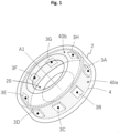
FIG. 1 is a perspective view showing the entire configuration of a tire assembly according to one embodiment; -
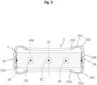
FIG. 2 is a longitudinal cross-sectional view of the tire assembly; -
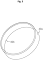
FIG. 3 is a perspective view showing the entire configuration of a sound absorbing material according to the one embodiment; -
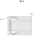
FIG. 4 illustrates a cut surface of the tire assembly; and -
FIG. 5 is a longitudinal cross-sectional view of a tire assembly according to a modification. - Hereinafter, a tire assembly according to one embodiment of the present invention will be described with reference to the drawings.
-
FIG. 1 is a perspective view showing the entire configuration of atire assembly 1 according to one embodiment of the present invention, andFIG. 2 is a longitudinal cross-sectional view of the tire assembly 1 (a view of a cross-section of thetire assembly 1 along the radial direction thereof). Thetire assembly 1 is a tire product having additional functions such as a sensing function, a power generation function, or a signal transmission function, and is configured to be mounted to each of the wheels of various vehicles and rotate on a road surface. As shown inFIG. 1 , thetire assembly 1 includes atire 2, asound absorbing material 4, and a plurality offunctional components 3A to 3H. Thesound absorbing material 4 is fixed to aninner surface 20 of thetire 2. The plurality offunctional components 3A to 3H are each placed between theinner surface 20 and an outercircumferential surface 40a of thesound absorbing material 4, or on an innercircumferential surface 40b side of thesound absorbing material 4. Each component will be described below. - The
tire 2 is composed of a vulcanized rubber or the like and has elasticity. The type and the structure of thetire 2 are not particularly limited, but thetire 2 of the present embodiment includes atread portion 200,sidewall portions 201,shoulder portions 202, andbead portions 203 as shown inFIG. 2 . Thetread portion 200 is a portion that defines a lateral circumferential surface of thetire assembly 1, and comes into contact with a road surface and generates friction to advance a vehicle. The sidewall portions 201 bend and flex to absorb impacts from a road surface. Theshoulder portions 202 are portions that are continuous to thetread portions 200 and thesidewall portions 201. Thebead portions 203 are portions that are fixed to a wheel rim, and include therein bead wires which are not shown. Thetire 2 further has theinner surface 20 which defines the inner space of thetire 2. Hereinafter, an annular surface, of theinner surface 20, corresponding to the back side of thetread portion 200 is sometimes referred to asinner surface 20a to distinguish the annular surface from the other portions. -
FIG. 3 is a perspective view showing the entire configuration of thesound absorbing material 4 according to the present embodiment. Thesound absorbing material 4 is a component for absorbing and reducing the cavity resonance sound generated in the inner space of thetire 2 as thetire assembly 1 rotates. In the present embodiment, thesound absorbing material 4 is formed in an annular shape, and is fixed to theinner surface 20 over the entire circumference of theinner surface 20a. That is, the circumferential length of the outercircumferential surface 40a of thesound absorbing material 4 is substantially equal to the circumferential length of theinner surface 20a. The shape of thesound absorbing material 4 is not particularly limited, and thesound absorbing material 4 may have a cross-sectional shape in which the thickness thereof varies along the circumferential direction or the width direction, for example. In addition, for example, thesound absorbing material 4 may be formed such that portions thereof corresponding to thefunctional components 3A to 3H are thinner than the other portion thereof in order to absorb the thicknesses of thefunctional components 3A to 3H described later. - In the present embodiment, the
sound absorbing material 4 is composed of a sponge material. The sponge material is not particularly limited as long as the sponge material is a porous structure having cushioning properties, and may be, for example, a rubber or synthetic resin foam, a three-dimensional structure formed by accumulating fibrous members, or the like. A chloroprene rubber (CR) sponge, an ethylene-propylene rubber (EPR, EPDMR) sponge, and a nitrile rubber (NBR) sponge are preferable as the rubber foam, and an ether-based polyurethane sponge, an ester-based polyurethane sponge, and a polyethylene sponge are preferable as the synthetic resin foam. These sponge materials may each have a closed cell structure, a continuous cell structure, or a mixed structure of closed cells and continuous cells. - The specific gravity of the
sound absorbing material 4 is preferably not less than 0.005 and not greater than 0.05. The thickness of thesound absorbing material 4 in an uncompressed state where no external force is applied and thesound absorbing material 4 is not compressed is preferably not less than 5 mm and not greater than 30 mm. In the case where the thickness of thesound absorbing material 4 is not constant, the thickness of the entiresound absorbing material 4 is preferably not less than 5 mm and not greater than 30 mm. - Furthermore, the cross-sectional area of the
sound absorbing material 4 in a cut surface P1 (seeFIG. 4 ) of thetire assembly 1 extending outward in the radial direction of thetire 2 from a central axis A1 of thetire 2 is preferably not less than 3% and not greater than 20% of the cross-sectional area of the inner space defined by theinner surface 20 when thetire 2 is fitted on a standardized rim (a wheel having the standardized rim) and the air pressure of thetire 2 is a standardized air pressure. - The method for fixing the
sound absorbing material 4 to thetire 2 is not particularly limited. Thesound absorbing material 4 may be fixed to theinner surface 20 via an adhesive or a pressure sensitive adhesive. Alternatively, one or more protrusions may be formed in thetire 2 so as to project from theinner surface 20 into the inner space, one or more through holes corresponding to the one or more protrusions may be formed in thesound absorbing material 4, and thesound absorbing material 4 may be fixed to thetire 2 by causing the one or more protrusions to penetrate through the corresponding one or more through holes. Still alternatively, fixing members capable of being coupled with each other may be provided to the outer circumferential surfaces of theinner surface 20 and thesound absorbing material 4, respectively, and thesound absorbing material 4 may be fixed to thetire 2 by coupling these fixing members with each other. Examples of the fixing members include a pair of hook and loop fasteners, a pair of magnets, a pair of a magnet and a magnetic material, and a pair of snap buttons. Thesound absorbing material 4 may be fixed to thetire 2 so as to be non-separable from theinner surface 20, or may be fixed to thetire 2 so as to be separable from theinner surface 20. - The plurality of functional components are placed so as to be spaced apart from each other such that the functional components are distributed along the circumferential direction of the
tire 2. Thetire assembly 1 of the present embodiment includes the eightfunctional components 3A to 3H, but the number of functional components is not particularly limited. As described above, thefunctional components 3A to 3H are each placed between theinner surface 20a and the outercircumferential surface 40a or on the innercircumferential surface 40b side of thesound absorbing material 4. At least one of the plurality of functional components is preferably placed between theinner surface 20a and the outercircumferential surface 40a. In the present embodiment, thefunctional components 3A to 3G are placed between theinner surface 20a and the outercircumferential surface 40a, and thefunctional component 3H is placed on the innercircumferential surface 40b. Each of thefunctional components 3A to 3G may be fixed on theinner surface 20, may be fixed on the outercircumferential surface 40a of thesound absorbing material 4, or may be fixed on both theinner surface 20 and the outercircumferential surface 40a. Each of thefunctional components 3A to 3H may be any of a power generation device, a sensor device, a secondary battery, a capacitor, an antenna device, a transmitter, a processor, a memory, and a circuit. That is, the plurality of functional components included in thetire assembly 1 may include two or more functional components of the same type, and may not necessarily include all of the types of functional components described above. - The power generation device is not particularly limited as long as the power generation device generates power using deformation of the
tire 2, and may be a device using a piezoelectric element, a device that generates power using contact electrification, or the like. The device that generates power using contact electrification is, for example, a device that has a first surface formed from an insulating material and a second surface formed from an insulating material different from that of the first surface and generates a potential difference due to a change in the true area of contact between the first surface and the second surface, or the like. The power generation device generates power in conjunction with rotation of thetire 2. Therefore, the power generation device can also be used as a sensor for monitoring at least one of a tire rotation speed, a tire wear state, a road surface condition, and a ground-contact state, by detecting a change in the potential difference generated in the power generation device. In the case where thetire assembly 1 includes a secondary battery or a capacitor as another functional component, the electricity generated in the power generation device may be stored in the secondary battery or the capacitor. In the case where thetire assembly 1 includes an electronic device such as a sensor device, an antenna, a transmitter, a processor, or a memory as another functional component, the electricity generated in the power generation device may be supplied to these electronic devices as appropriate. - The sensor device is not particularly limited as long as the sensor device acquires sensing data inside the
tire assembly 1, and may be, for example, an air pressure sensor, a temperature sensor, a speed sensor, an acceleration sensor, a rotation speed sensor, a rotation angle sensor, or the like. In the case where thetire assembly 1 includes a processor as another functional component, the sensing data acquired by the sensor device may be processed by the processor into processed data. In the case where thetire assembly 1 also includes a memory as another functional component, the sensing data acquired by the sensor device or the processed data thereof may be stored in the memory. In the case where thetire assembly 1 further includes an antenna as another functional component, the sensing data acquired by the sensor device or the processed data thereof may be transmitted via the antenna to a device external to thetire assembly 1 such as an in-vehicle device. - The processor is not particularly limited as long as the processor executes programs, calculates, converts, processes, and transmits/receives data, and controls the operation of other functional components, for example, and is composed of, for example, an IC chip including an arithmetic unit, a register, and a peripheral circuit, etc., as hardware. In addition to generating processed data and transmitting data as described above, the processor may distribute the electricity generated in the power generator and receive data from external devices via an antenna, for example.
- The memory is not particularly limited as long as the memory has a data storage area, and is composed of, for example, a flash memory chip as hardware. The memory may be a non-volatile rewritable memory, or may be a non-rewritable memory in which programs, etc., are stored, or a volatile memory for temporarily storing data.
- The secondary battery is not particularly limited as long as the secondary battery is a battery that can be used repeatedly by recharging, and may be, for example, a lithium ion battery, a lithium battery, an alkaline battery, a silver oxide/zinc oxide battery, an all-solid-state battery, or the like. The secondary battery can be used to supply electricity to the above electronic devices.
- The capacitor is not particularly limited, and any type of capacitor can be used. The capacitor may be used to keep a voltage constant or reduce noise as necessary in addition to storing the electricity generated in the power generation device and supplying the electricity to the above electronic devices.
- The antenna device is not particularly limited as long as the antenna device transmits and receives radio waves, and any type of antenna device can be used. The antenna device may include, in addition to an antenna itself for converting radio waves and electric current into each other, a communication device for establishing wireless communication between the
tire assembly 1 and a device external to thetire assembly 1. - The transmitter is not particularly limited as long as the transmitter transmits radio waves. The transmitter may be, for example, a BLUETOOTH (registered trademark) transmitter, a location information transmitter that transmits location information acquired from a satellite positioning system such as GPS to an external device, or the like.
- The circuit may be a circuit for operating other functional components, or a circuit for operating other functional components in coordination with each other, and the configuration thereof is not particularly limited.
- At least some of the
functional components 3A to 3H placed so as to be distributed along the circumferential direction of thetire 2 may be electrically connected to each other using a lead wire or the like (not shown). However, from the viewpoint of suppressing vibration and noise of thetire assembly 1, the mass of the lead wire or the like to be used is preferably sufficiently small with respect to each of the masses of thefunctional components 3A to 3H. A preferable range of each of the masses of thefunctional components 3A to 3H will be described later. - If the mass balance along the circumferential direction of a tire is significantly disrupted by providing functional components on the inner side of the tire, unwanted vibration may be caused due to rotation of the tire, thereby impairing comfortable running of a vehicle. First-order radial force variation (RFV) mainly contributes to this vibration. In the
tire assembly 1, in order to suppress vibration caused by the radial force variation, the functional components are preferably placed such that the masses of the functional components as a whole are distributed as evenly as possible and at as equal intervals as possible along the circumferential direction of thetire 2. Therefore, in the present embodiment, thefunctional components 3A to 3H are placed such that the centers of gravity thereof are spaced apart in the circumferential direction of thetire 2 at 45 degree intervals based on the central axis A1 of the tire 2 (for convenience of description, the positions of the centers of gravity of thefunctional components 3A to 3H are indicated by black dots in the drawing). However, there may be an error of ±10 degrees or less in the intervals based on the central axis A1. That is, the fact that the masses of the plurality of functional components are "distributed at equal intervals" along the circumferential direction of the tire includes, in addition to the case where the centers of gravity of the respective functional components are located so as to be spaced apart at equal angles, the case where the centers of gravity of the respective functional components are located at intervals including an error of ±10 degrees or less. - In addition, in order to distribute the masses of the functional components as a whole as evenly as possible, the difference in mass of each functional component to be distributed and placed is preferably made as small as possible. More specifically, the difference between the maximum value and the minimum value of the masses of the respective functional components is preferably not greater than 20 g. When the difference in mass of each functional component is set to not greater than the above upper limit, the mass imbalance caused by the functional components can be cancelled to a preferable degree by adjustment after the
tire assembly 1 is mounted on the wheel. On the other hand, if the difference in mass of each functional component exceeds the above upper limit, even when the mass balance is adjusted with a counterweight after thetire assembly 1 is mounted on the wheel, the radial force variation is increased by the difference in mass of each functional component to be distributed and placed, and the influence of vibration is increased, thus leading to deterioration of ride comfort. - In addition, in order to suppress the vibration of the
tire assembly 1 caused by a high-order component of the radial force variation, each of the masses of the functional component itself is preferably small. Specifically, each of the masses of the functional components is preferably not greater than 20 g. If each of the masses of the functional components exceeds 20 g, even when the mass balance is adjusted with a counterweight after thetire assembly 1 is mounted on the wheel, the radial force variation is increased by the masses of the functional components, and the influence of vibration is increased, thus leading to deterioration of ride comfort. - The number for distributing the masses of the plurality of functional components along the circumferential direction of the tire 2 (the number of locations where the plurality of functional components are placed along the circumferential direction of the tire 2) is not particularly limited, but is preferably not less than 4, more preferably not less than 8, and further preferably not less than 10, and is preferably not greater than 12. That is, the plurality of functional components are preferably distributed at at least four locations along the circumferential direction of the
tire 2. - As described above, the mass imbalance caused by the functional components can be adjusted with a counterweight or the like after the
tire assembly 1 is mounted on the wheel. However, during rotation of thetire assembly 1, mass imbalance (vibration) is caused when each of the locations where the functional components are placed comes into contact with a road surface, and this mass imbalance is transmitted as an excitation force from thetire assembly 1 to the vehicle. The excitation force increases in proportion to the square of the rotation speed of thetire assembly 1. As the number of locations where the functional components are placed along the circumferential direction of thetire 2 increases, the number of times the mass imbalance is caused during one rotation of thetire assembly 1 increases, so that an excitation frequency at which the excitation force is applied to the vehicle is increased, while the rotation speed of thetire assembly 1 at which the excitation frequency coincides with the resonance frequency of the vehicle is decreased. That is, when the number of locations where the functional components are placed is denoted by n, the rotation speed of thetire assembly 1 at which the excitation frequency coincides with the resonance frequency of the vehicle is 1/n times. When the excitation frequency and the resonance frequency coincide with each other, the vibration of the vehicle is increased, but usually, even when the excitation frequency and the resonance frequency merely become closer to each other, the vibration of the vehicle is increased as well. - Due to the above, if the locations where the functional components are placed increases, when the rotation speed of the
tire assembly 1 is low (that is, the excitation force is small), since the excitation frequency and the resonance frequency coincide with each other, the vibration transmitted to the vehicle becomes small. Thus, the effect of suppressing the radial force variation becomes more significant when the number of locations where the functional components are placed is not less than 4. However, as the number of locations where the functional components are placed increases, a wiring structure connecting the functional components to each other becomes more complicated, thereby increasing the time and effort for processing. According to a study by the present inventors, if the number of locations where the functional components are placed exceeds 10, the effect of suppressing the radial force variation tends to reach its peak. That is, when the number of locations where the functional components are placed exceeds 10, the running speed at which the vehicle resonates becomes sufficiently low, so that the vibration of the vehicle at the speed at which the vehicle normally runs remains almost unchanged even if the number of locations where the functional components are placed is increased further. Therefore, the number for distributing the masses of the plurality of functional components is preferably determined in consideration of the balance between the time and effort for processing for connecting the functional components to each other, a degree of complication of the structure for connecting the functional components to each other, and the effect of suppressing the RFV. - Even if the masses of the plurality of functional components as a whole are evenly distributed at as equal intervals as possible along the circumferential direction of the
tire 2, since the plurality of functional components are placed, the cavity resonance sound caused by the high-order component of the radial force variation can increase. The cavity resonance sound is noise generated when the vehicle having thetire assembly 1 mounted thereon runs on a road surface and the air inside thetire assembly 1 vibrates and resonates due to the impact received by thetire assembly 1 from the road surface. The cavity resonance sound is generated mainly when the vehicle runs at a speed of about 30 km to 80 km per hour, although this depends on the size of thetire 2 and the number of functional components. In addition, according to a study by the present inventors, the cavity resonance sound is increased when the number of locations where the functional components are placed is not less than 7. However, since thetire assembly 1 includes thesound absorbing material 4, the cavity resonance sound caused by the plurality of functional components can be reduced. - Which of the plurality of functional components is placed on the outer
circumferential surface 40a side of thesound absorbing material 4, and which of the plurality of functional components is placed on the innercircumferential surface 40b side of thesound absorbing material 4, can be selected as appropriate according to the convenience of wiring, the masses and the characteristics of the functional components, the thickness and the hardness of thesound absorbing material 4, etc. For example, if the sponge material of thesound absorbing material 4 is relatively hard, or if the sponge material itself is relatively soft but the thickness thereof is relatively large, the functional components can be placed on the innercircumferential surface 40b side from the viewpoint of reliably mounting thesound absorbing material 4 on theinner surface 20. This is because, if the sponge material of thesound absorbing material 4 is relatively hard or relatively thick, it can be relatively difficult to reliably attach thesound absorbing material 4 to theinner surface 20 of thetire 2 via an adhesive or a pressure sensitive adhesive. The thickness of the sponge material may be said to be relatively large if the thickness of the sponge material is not less than 20 mm, and may be said to be relatively small if the thickness of the sponge material is less than 20 mm. The hardness of the sponge material may be said to be relatively hard if the ASKER C hardness thereof is not less than 30°, and may be said to be relatively soft if the ASKER C hardness thereof is less than 30°. Furthermore, a continuous-cell-type sponge material having flexibility may be said to be relatively soft. Moreover, the capacitor which is likely to be influenced by vibration can be placed on the innercircumferential surface 40b side from the viewpoint of suppressing the influence of vibration. On the other hand, if a functional component is placed on the innercircumferential surface 40b side, the mass of the functional component may add a load to thesound absorbing material 4 due to vibration during running, so that it may be preferable to place the functional component on the outercircumferential surface 40a side. In the case where a functional component is placed between the outercircumferential surface 40a and theinner surface 20a of thetire 2, the functional component can be more reliably fixed to thetire 2 having high stiffness. Thus, generation of vibration or cavity resonance sound can be suppressed. In addition, the sensor can acquire more accurate information when being fixed to theinner surface 20a of thetire 2. - Although the one embodiment of the present invention has been described above, the present invention is not limited to the above embodiment, and various modifications can be made without departing from the gist of the present invention. For example, the following modifications are possible. In addition, the gist of the following modifications can be combined as appropriate.
- (1) It is sufficient that the plurality of functional components are placed such that the centers of gravity thereof are distributed at equal intervals along the circumferential direction of the
tire 2, and the positions of the centers of gravity thereof along the width direction of the tire 2 (direction parallel to the central axis A1) may be different from each other as shown inFIG. 5 . - (2) The
tire assembly 1 may constitute a system for monitoring the state of thetire 2 or the vehicle by means of the functional components, together with an in-vehicle device installed in the vehicle or a portable information processing terminal such as a laptop computer, a smartphone, a mobile phone, or a tablet.
Claims (12)
- A tire assembly (1) comprising:a tire (2);a sound absorbing material (4) placed on an inner side of the tire (2); anda plurality of functional components (3A to 3H) placed on the inner side of the tire (2), whereinthe plurality of functional components (3A to 3H) are placed such that masses of the plurality of functional components (3A to 3H) as a whole are distributed along a circumferential direction of the tire (2).
- The tire assembly (1) according to claim 1, wherein the plurality of functional components (3A to 3H) are each any of a power generation device, a sensor device, a secondary battery, a capacitor, an antenna device, a transmitter, a processor, a memory, and a circuit.
- The tire assembly (1) according to claim 1 or 2, wherein at least one of the plurality of functional components (3A to 3H) is placed between an inner surface (20, 20a) of the tire (2) and the sound absorbing material (4).
- The tire assembly (1) according to one of claims 1 to 3, wherein the plurality of functional components (3A to 3H) are placed such that the masses of the plurality of functional components (3A to 3H) as a whole are distributed at equal intervals along the circumferential direction of the tire (2).
- The tire assembly (1) according to one of claims 1 to 4, wherein the plurality of functional components (3A to 3H) are placed so as to be distributed at at least four locations along the circumferential direction of the tire (2).
- The tire assembly (1) according to one of claims 1 to 5, wherein a difference between a maximum value and a minimum value of the masses of the plurality of functional components (3A to 3H) placed so as to be distributed at equal intervals along the circumferential direction of the tire (2) is not greater than 20 g.
- The tire assembly (1) according to one of claims 1 to 6, wherein the sound absorbing material (4) is composed of a sponge material.
- The tire assembly (1) according to claim 7, wherein the sponge material has a specific gravity of not less than 0.005 and not greater than 0.05.
- The tire assembly (1) according to one of claims 1 to 8, wherein a cross-sectional area of the sound absorbing material (4) in a cut surface (P1) of the tire assembly (1) extending outward in a radial direction of the tire (2) from a central axis (A1) of the tire (2) is not less than 3% and not greater than 20% of a cross-sectional area of an inner space defined by an inner surface (20, 20a) of the tire (2) in a state where the tire (2) is fitted on a standardized rim and an air pressure of the tire (2) is a standardized air pressure.
- The tire assembly (1) according to one of claims 7 to 9, wherein the sponge material has a thickness of not less than 5 mm and not greater than 30 mm.
- The tire assembly (1) according to one of claims 7 to 10, wherein the sponge material is selected from the group consisting of a chloroprene rubber sponge, an ethylene-propylene rubber sponge, a nitrile rubber sponge, an ether-based polyurethane sponge, an ester-based polyurethane sponge, and a polyethylene sponge.
- The tire assembly (1) according to one of claims 1 to 11, wherein each of the masses of the plurality of functional components (3A to 3H) is not greater than 20 g.
Applications Claiming Priority (1)
| Application Number | Priority Date | Filing Date | Title |
|---|---|---|---|
| JP2022208704A JP2024092626A (en) | 2022-12-26 | 2022-12-26 | Tire Assembly |
Publications (1)
| Publication Number | Publication Date |
|---|---|
| EP4393729A1 true EP4393729A1 (en) | 2024-07-03 |
Family
ID=88600277
Family Applications (1)
| Application Number | Title | Priority Date | Filing Date |
|---|---|---|---|
| EP23206722.3A Pending EP4393729A1 (en) | 2022-12-26 | 2023-10-30 | Tire assembly |
Country Status (4)
| Country | Link |
|---|---|
| US (1) | US20240208274A1 (en) |
| EP (1) | EP4393729A1 (en) |
| JP (1) | JP2024092626A (en) |
| CN (1) | CN118254508A (en) |
Citations (5)
| Publication number | Priority date | Publication date | Assignee | Title |
|---|---|---|---|---|
| EP1728650A2 (en) * | 2005-06-01 | 2006-12-06 | Sumitomo Rubber Industries, Ltd. | Pneumatic tire |
| JP2010125920A (en) * | 2008-11-26 | 2010-06-10 | Alps Electric Co Ltd | Mounting structure of tire information transmitter |
| JP2017108536A (en) | 2015-12-09 | 2017-06-15 | 株式会社ブリヂストン | Power generator and tire |
| US10286737B2 (en) * | 2013-11-21 | 2019-05-14 | The Yokohama Rubber Co., Ltd. | Pneumatic tire |
| EP3501858A1 (en) * | 2017-12-19 | 2019-06-26 | Sumitomo Rubber Industries, Ltd. | Pneumatic tyre and pneumatic tyre and rim assembly |
-
2022
- 2022-12-26 JP JP2022208704A patent/JP2024092626A/en active Pending
-
2023
- 2023-10-30 EP EP23206722.3A patent/EP4393729A1/en active Pending
- 2023-11-15 US US18/509,387 patent/US20240208274A1/en active Pending
- 2023-11-29 CN CN202311622257.6A patent/CN118254508A/en active Pending
Patent Citations (5)
| Publication number | Priority date | Publication date | Assignee | Title |
|---|---|---|---|---|
| EP1728650A2 (en) * | 2005-06-01 | 2006-12-06 | Sumitomo Rubber Industries, Ltd. | Pneumatic tire |
| JP2010125920A (en) * | 2008-11-26 | 2010-06-10 | Alps Electric Co Ltd | Mounting structure of tire information transmitter |
| US10286737B2 (en) * | 2013-11-21 | 2019-05-14 | The Yokohama Rubber Co., Ltd. | Pneumatic tire |
| JP2017108536A (en) | 2015-12-09 | 2017-06-15 | 株式会社ブリヂストン | Power generator and tire |
| EP3501858A1 (en) * | 2017-12-19 | 2019-06-26 | Sumitomo Rubber Industries, Ltd. | Pneumatic tyre and pneumatic tyre and rim assembly |
Also Published As
| Publication number | Publication date |
|---|---|
| JP2024092626A (en) | 2024-07-08 |
| CN118254508A (en) | 2024-06-28 |
| US20240208274A1 (en) | 2024-06-27 |
Similar Documents
| Publication | Publication Date | Title |
|---|---|---|
| US8452477B2 (en) | Method and system for managing data transmission from a plurality of sensor devices included in a tyre | |
| US11065921B2 (en) | Tire-mounted sensor having vibration transmission member to transmit vibration added to tire with respect to vibration detection element | |
| US9908374B2 (en) | Tire module with piezo-electric transducer and tire equipped therewith | |
| KR101871896B1 (en) | Tire sensor and manufacturing method thereof | |
| US20110309927A1 (en) | Intelligent tire systems and methods | |
| EP1681660A1 (en) | Tire sensor device and tire information transmission method | |
| JP7389210B2 (en) | sensor module | |
| WO2019021730A1 (en) | Pneumatic tire | |
| US20220289056A1 (en) | Charging control method for electric moving body, and electric moving body | |
| KR101846207B1 (en) | Tire sensor for installation in tire | |
| US20030172729A1 (en) | Device for detecting the tire pressure of a motor vehicle tire | |
| US20210021015A1 (en) | Reader system for tire with an integrated rfid and tpms sensor | |
| JP2012051429A (en) | Tire sensor and tire state monitoring device | |
| JP3949568B2 (en) | Transponder for tire condition monitoring device | |
| US20180301035A1 (en) | Bicycle notification device including attaching portion transmitter and power generator | |
| US20090134710A1 (en) | Inductive coupling of pulses from piezoelectric device | |
| CN102514455A (en) | Tire pressure monitoring system without assembly | |
| US11890899B2 (en) | Pneumatic tire, pneumatic tire assembly, and power supply system | |
| EP4393729A1 (en) | Tire assembly | |
| US20060144132A1 (en) | Sensor device for tire | |
| CN118254507A (en) | Tire assembly | |
| US20260042321A1 (en) | Tire with Treadwear Monitoring | |
| WO2007040536A2 (en) | System and method for harvesting electric power from a rotating tire’s acoustic energy | |
| JP2006240598A (en) | Patch for mounting module and pneumatic tire having the same | |
| KR20150120807A (en) | Wireless power transmitting apparatus for vehicle |
Legal Events
| Date | Code | Title | Description |
|---|---|---|---|
| PUAI | Public reference made under article 153(3) epc to a published international application that has entered the european phase |
Free format text: ORIGINAL CODE: 0009012 |
|
| STAA | Information on the status of an ep patent application or granted ep patent |
Free format text: STATUS: THE APPLICATION HAS BEEN PUBLISHED |
|
| AK | Designated contracting states |
Kind code of ref document: A1 Designated state(s): AL AT BE BG CH CY CZ DE DK EE ES FI FR GB GR HR HU IE IS IT LI LT LU LV MC ME MK MT NL NO PL PT RO RS SE SI SK SM TR |
|
| STAA | Information on the status of an ep patent application or granted ep patent |
Free format text: STATUS: REQUEST FOR EXAMINATION WAS MADE |
|
| 17P | Request for examination filed |
Effective date: 20241014 |
|
| RBV | Designated contracting states (corrected) |
Designated state(s): AL AT BE BG CH CY CZ DE DK EE ES FI FR GB GR HR HU IE IS IT LI LT LU LV MC ME MK MT NL NO PL PT RO RS SE SI SK SM TR |
|
| P01 | Opt-out of the competence of the unified patent court (upc) registered |
Free format text: CASE NUMBER: APP_12390/2025 Effective date: 20250313 |