EP4393724A1 - Retreaded tire - Google Patents
Retreaded tire Download PDFInfo
- Publication number
- EP4393724A1 EP4393724A1 EP23209292.4A EP23209292A EP4393724A1 EP 4393724 A1 EP4393724 A1 EP 4393724A1 EP 23209292 A EP23209292 A EP 23209292A EP 4393724 A1 EP4393724 A1 EP 4393724A1
- Authority
- EP
- European Patent Office
- Prior art keywords
- groove
- tire
- dimples
- shoulder
- tire according
- Prior art date
- Legal status (The legal status is an assumption and is not a legal conclusion. Google has not performed a legal analysis and makes no representation as to the accuracy of the status listed.)
- Granted
Links
Images


Classifications
-
- B—PERFORMING OPERATIONS; TRANSPORTING
- B60—VEHICLES IN GENERAL
- B60C—VEHICLE TYRES; TYRE INFLATION; TYRE CHANGING; CONNECTING VALVES TO INFLATABLE ELASTIC BODIES IN GENERAL; DEVICES OR ARRANGEMENTS RELATED TO TYRES
- B60C11/00—Tyre tread bands; Tread patterns; Anti-skid inserts
- B60C11/03—Tread patterns
- B60C11/13—Tread patterns characterised by the groove cross-section, e.g. for buttressing or preventing stone-trapping
- B60C11/1307—Tread patterns characterised by the groove cross-section, e.g. for buttressing or preventing stone-trapping with special features of the groove walls
-
- B—PERFORMING OPERATIONS; TRANSPORTING
- B29—WORKING OF PLASTICS; WORKING OF SUBSTANCES IN A PLASTIC STATE IN GENERAL
- B29D—PRODUCING PARTICULAR ARTICLES FROM PLASTICS OR FROM SUBSTANCES IN A PLASTIC STATE
- B29D30/00—Producing pneumatic or solid tyres or parts thereof
- B29D30/06—Pneumatic tyres or parts thereof (e.g. produced by casting, moulding, compression moulding, injection moulding, centrifugal casting)
- B29D30/52—Unvulcanised treads, e.g. on used tyres; Retreading
- B29D30/54—Retreading
-
- B—PERFORMING OPERATIONS; TRANSPORTING
- B60—VEHICLES IN GENERAL
- B60C—VEHICLE TYRES; TYRE INFLATION; TYRE CHANGING; CONNECTING VALVES TO INFLATABLE ELASTIC BODIES IN GENERAL; DEVICES OR ARRANGEMENTS RELATED TO TYRES
- B60C11/00—Tyre tread bands; Tread patterns; Anti-skid inserts
- B60C11/02—Replaceable treads
-
- B—PERFORMING OPERATIONS; TRANSPORTING
- B60—VEHICLES IN GENERAL
- B60C—VEHICLE TYRES; TYRE INFLATION; TYRE CHANGING; CONNECTING VALVES TO INFLATABLE ELASTIC BODIES IN GENERAL; DEVICES OR ARRANGEMENTS RELATED TO TYRES
- B60C11/00—Tyre tread bands; Tread patterns; Anti-skid inserts
- B60C11/03—Tread patterns
- B60C11/04—Tread patterns in which the raised area of the pattern consists only of continuous circumferential ribs, e.g. zig-zag
- B60C11/042—Tread patterns in which the raised area of the pattern consists only of continuous circumferential ribs, e.g. zig-zag further characterised by the groove cross-section
- B60C11/045—Tread patterns in which the raised area of the pattern consists only of continuous circumferential ribs, e.g. zig-zag further characterised by the groove cross-section the groove walls having a three-dimensional shape
-
- B—PERFORMING OPERATIONS; TRANSPORTING
- B60—VEHICLES IN GENERAL
- B60C—VEHICLE TYRES; TYRE INFLATION; TYRE CHANGING; CONNECTING VALVES TO INFLATABLE ELASTIC BODIES IN GENERAL; DEVICES OR ARRANGEMENTS RELATED TO TYRES
- B60C11/00—Tyre tread bands; Tread patterns; Anti-skid inserts
- B60C11/03—Tread patterns
- B60C11/13—Tread patterns characterised by the groove cross-section, e.g. for buttressing or preventing stone-trapping
- B60C11/1353—Tread patterns characterised by the groove cross-section, e.g. for buttressing or preventing stone-trapping with special features of the groove bottom
-
- B—PERFORMING OPERATIONS; TRANSPORTING
- B60—VEHICLES IN GENERAL
- B60C—VEHICLE TYRES; TYRE INFLATION; TYRE CHANGING; CONNECTING VALVES TO INFLATABLE ELASTIC BODIES IN GENERAL; DEVICES OR ARRANGEMENTS RELATED TO TYRES
- B60C11/00—Tyre tread bands; Tread patterns; Anti-skid inserts
- B60C11/01—Shape of the shoulders between tread and sidewall, e.g. rounded, stepped or cantilevered
-
- B—PERFORMING OPERATIONS; TRANSPORTING
- B60—VEHICLES IN GENERAL
- B60C—VEHICLE TYRES; TYRE INFLATION; TYRE CHANGING; CONNECTING VALVES TO INFLATABLE ELASTIC BODIES IN GENERAL; DEVICES OR ARRANGEMENTS RELATED TO TYRES
- B60C11/00—Tyre tread bands; Tread patterns; Anti-skid inserts
- B60C11/03—Tread patterns
- B60C11/13—Tread patterns characterised by the groove cross-section, e.g. for buttressing or preventing stone-trapping
- B60C11/1307—Tread patterns characterised by the groove cross-section, e.g. for buttressing or preventing stone-trapping with special features of the groove walls
- B60C2011/133—Tread patterns characterised by the groove cross-section, e.g. for buttressing or preventing stone-trapping with special features of the groove walls comprising recesses
Definitions
- the present invention relates to a retreaded tire.
- the "standard inner pressure” is air pressure specified for the concerned tire by a standard included in a standardization system on which the tire is based, for example, the maximum air pressure in JATMA, maximum value listed in the "TIRE LOAD LIMITS AT VARIOUS COLD INFLATION PRESSURES" table in TRA, and "INFLATION PRESSURE” in ETRTO.
- the multiple dimples 25 are provided on at least one of the pair of the groove wall surfaces 24, specifically, the multiple dimples 25 are provided at least on the first groove wall surface 21.
- a plurality of the dimples 25 is also provided on the second groove wall surface 22, and in a more preferred embodiment, a plurality of the dimples 25 are also provided on the groove bottom surface 23.
- the present invention is not limited to such a manner. That is, the present invention can include an embodiment in which a plurality of the dimples 25 is provided only on the second groove wall surface 22, or an embodiment in which a plurality of the dimples 25 is provided only on the groove bottom surface 23.
- one of the groove wall surfaces 24 (each of the groove wall surfaces 24 in the present embodiment) included in one 1-pitch area (Pa) has one or more rows each having 1 to 5 dimples 25 arranged in the tire radial direction (lateral direction on the groove wall surfaces 24 in FIG. 4 ).
- one (or each) of the groove wall surfaces 24 has one or more rows each having 1 to 5 dimples 25 arranged in the tire radial direction in each 1-pitch area (Pa).
- 1 to 5 dimple rows 27 in which a plurality of the dimples 25 are arranged in the tire circumferential direction are arranged on one groove wall surface 24.
- one groove wall surface 24 has two dimple rows 27 arranged therein.
- the present invention is not limited to such a mode.
- each of the dimples 25 has a maximum diameter A1 of 1 to 5 mm, preferably 2.5 to 4.5 mm. Further, each of the dimples 25 has a maximum depth (d1) of 1 to 3 mm. Therefore, the steering stability and the peeling resistance are improved in a good balance.
- the tire 1 of the present invention may be manufactured by, for example, adhering a vulcanized tread rubber (2a) on which the above-mentioned dimples 25 are arranged to the base tire (1a), or after the vulcanized tread rubber (2a) without the dimples 25 is adhered to the base tire (1a), the dimples 25 may be formed on the tread rubber (2a).
Landscapes
- Engineering & Computer Science (AREA)
- Mechanical Engineering (AREA)
- Tires In General (AREA)
Abstract
Description
- This application claims the benefit of foreign priority to Japanese Patent Application No.
JP2022-209934, filed December 27, 2022 - The present invention relates to a retreaded tire.
-
Japanese Unexamined Patent Application Publication No. 2011-235783 - It is possible that damages such as a tread rubber peeling off from a base tire may occur to a retreaded tire during running.
- The present invention was made in view of the above, and a primary object thereof is to provide a retreaded tire with improved peeling resistance of the tread rubber to peeling off from the base tire.
- The present invention is a retreaded tire including a base tire and a tread rubber for retread adhered to the base tire, wherein the tread rubber includes a first tread edge and a first shoulder circumferential groove adjacent to the first tread edge and extending continuously in a tire circumferential direction, and the first shoulder circumferential groove has a groove surface provided with a plurality of dimples.
- By adopting the above configuration, the retreaded tire of the present invention can improve the peeling resistance of the tread rubber to peeling off from the base tire.
-
-
FIG. 1 is a lateral cross-sectional view of a retreaded tire according to an embodiment of the present invention. -
FIG. 2 is a development view showing a ground contacting surface of a tread rubber ofFIG. 1 . -
FIG. 3 is an enlarged perspective view showing a groove surface of a first shoulder circumferential groove ofFIG. 1 . -
FIG. 4 is an enlarged development view of the groove surface of the first shoulder circumferential groove ofFIG. 3 . -
FIG. 5 is a cross-sectional view of a dimple. -
FIG. 6 is a cross-sectional view taken along A-A line ofFIG. 2 . - An embodiment of the present invention will now be described in conjunction with accompanying drawings.
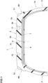
FIG. 1 is a lateral cross-sectional view of a retreaded tire 1 (hereinafter may be simply referred to as "tire 1") showing an embodiment of the present invention.FIG. 1 is the lateral cross-sectional view of the tire 1 in a standard state passing all through a tire rotational axis. As shown inFIG. 1 , the tire 1 of the present embodiment includes a base tire (1a), which is obtained by removing a tread rubber from a used tire, and a tread rubber (2a) for retread. This tread rubber (2a) is adhered to the base tire (1a). InFIG. 1 , bead portions of the base tire (1a) are omitted. The tire 1 of the present embodiment is suitable for use as a pneumatic tire for light or medium trucks, for example, but the present invention is not limited to such a mode. - In the case of pneumatic tires for which various standards have been established, the term "standard state" refers to a state in which the tire 1 is mounted on a standard rim, inflated to a standard inner pressure, and loaded with no tire load. In the case of tires for which various standards are not established, the standard sate means a state of standard usage according to the purpose of use of the tire and a state in which the tire is not mounted on a vehicle and is loaded with no tire load. In the present specification, unless otherwise noted, dimensions and the like of various parts of the tire are the values measured in the standard sate.
- The "standard rim" is a wheel rim specified for the concerned tire by a standard included in a standardization system on which the tire is based, for example, the "normal wheel rim" in JATMA, "Design Rim" in TRA, and "Measuring Rim" in ETRTO.
- The "standard inner pressure" is air pressure specified for the concerned tire by a standard included in a standardization system on which the tire is based, for example, the maximum air pressure in JATMA, maximum value listed in the "TIRE LOAD LIMITS AT VARIOUS COLD INFLATION PRESSURES" table in TRA, and "INFLATION PRESSURE" in ETRTO.
- The tire 1 includes a
tread portion 2 including the tread rubber (2a), a pair ofsidewall portions 3, and a pair of the bead portions (not shown). Thesidewall portions 3 are each connected to thetread portion 2 on a respective outer side in a tire axial direction and extend in a tire radial direction. The bead portions are each connected to a respective one of thesidewall portions 3 on an inner side in the tire radial direction. Further, although the tire 1 is provided with known configurations such as acarcass 6, atread reinforcing layer 7, and the like, descriptions thereof will be omitted here. - The tread rubber (2a) includes a first tread edge T1 and a second tread edge T2. The first tread edge T1 and the second tread edge T2 correspond to axially outermost ground contact positions when the tire 1 in the standard state is in contact with a flat surface with zero camber angle by being loaded with 90% of a standard tire load. Thereby, the tread rubber (2a) includes a ground contacting surface (2s), a
first buttress surface 8A, and asecond buttress surface 8B. The ground contacting surface (2s) is the surface that contacts the road surface when the tire is running and extends axially inward from the first tread edge T1 and the second tread edge T2. Thefirst buttress surface 8A extends axially inward from the first tread edge T1. Thesecond buttress surface 8B extends axially inward from the second tread edge T2. - In the case of pneumatic tires for which various standards have been established, the "standard tire load" refers to a tire load specified for the concerned tire by a standard included in a standardization system on which the tire is based, for example, the "maximum load capacity" in JATMA, maximum value listed in "TIRE LOAD LIMITS AT VARIOUS COLD INFLATION PRESSURES" table in TRA, and "LOAD CAPACITY" in ETRTO. Further, in the case of tires for which various standards are not established, the "standard tire load" refers to the maximum load applicable to the use of the tire in accordance with the above-mentioned standards.
-
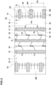
FIG. 2 is a development view showing the ground contacting surface (2s) of the tread rubber (2a). Various grooves are shaded by small dots inFIG. 2 . As shown inFIG. 2 , the tread rubber (2a) includes a first shouldercircumferential groove 11 adjacent to the first tread edge T1 and extending continuously in a tire circumferential direction. The tread rubber (2a) of the present embodiment includes a second shouldercircumferential groove 12 and a crowncircumferential groove 13 extending continuously in the tire circumferential direction. The second shouldercircumferential groove 12 is adjacent to the second tread edge T2. The crowncircumferential groove 13 is provided between the first shouldercircumferential groove 11 and the second shouldercircumferential groove 12, and is located on a tire equator (C) in the present embodiment. Each of the circumferential grooves has a groove width in the range from 5 to 15 mm, for example. Further, each of the circumferential grooves has a depth in the range from 5 to 15 mm, for example. - The tread rubber (2a) of the present embodiment includes a plurality of
land regions 15. Theland regions 15 includes a firstshoulder land region 16, a secondshoulder land region 17, a firstcrown land region 18, and a secondcrown land region 19. The firstshoulder land region 16 is demarcated axially outside the first shouldercircumferential groove 11 and includes the first tread edge T1. The secondshoulder land region 17 is demarcated axially outside the second shouldercircumferential groove 12 and includes the second tread edge T2. The firstcrown land region 18 is demarcated between the first shouldercircumferential groove 11 and the crowncircumferential groove 13. The secondcrown land region 19 is demarcated between the second shouldercircumferential groove 12 and the crowncircumferential groove 13. The tread rubber (2a) of the present embodiment is composed of these fourland regions 15 but is not limited to such a manner. -
FIG. 3 shows an enlarged perspective view showing agroove surface 20 of the first shouldercircumferential groove 11. As shown inFIG. 3 , thegroove surface 20 of the first shouldercircumferential groove 11 is provided with a plurality ofdimples 25. This improves the peeling resistance of the tread rubber (2a) to peeling off from the base tire (1a) (shown inFIG. 1 , and the same applies hereinafter). The reason for this is as follows. It should be noted that thedimples 25 are omitted inFIGs. 1 and2 . - Generally speaking, adhesion between the base tire and the tread rubber is low in retreaded tires. Therefore, the heat generated in the tread rubber during running tends to cause damage such as the tread rubber peeling off from the base tire. In particular, heat generation during running tends to occur at the shoulder portions, where the movement of the tread reinforcing layer is greater, thereby, it is important to reduce the heat generation at the shoulder portions of the tread rubber.
- In contrast, in the present invention, heat dissipation around the first
shoulder circumferential groove 11 is enhanced by a plurality of thedimples 25 on the groove surface of the firstshoulder circumferential groove 11, therefore, it is possible that the peeling resistance of the tread rubber (2a) to peeling off from the base tire (1a) (hereinafter may be simply referred to as "peeling resistance") is effectively improved. - Further, in an embodiment in which the tread rubber (2a) is adhered to the base tire (1a) by vulcanization and the
dimples 25 mentioned above are formed by the mold during this vulcanization, since thedimples 25 are provided, heat from the mold is easily transferred to the contact area between the tread rubber (2a) and the base tire (1a). Thereby, that the vulcanization process time can be shortened. Further, thedimples 25 described above also help to create turbulence in the grooves and reduce noise caused by the firstshoulder circumferential groove 11 during running. Furthermore, thedimples 25 described above can also be expected to have the effect of preventing foreign objects such as stones from getting caught in the firstshoulder circumferential groove 11. - Further detailed configurations of the present embodiment will be described below. It should be noted that each of the configurations described below indicates a specific aspect of the present embodiment. Therefore, it goes without saying that the present invention can exert the effects described above even if it does not have the configurations described below. Further, even if any one of the configurations described below is applied alone to the tire of the present invention having the features described above, performance improvement can be expected in accordance with each configuration. Furthermore, when some of the configurations described below are applied in combination, a combined performance improvement can be expected according to each configuration.
-
FIG. 4 is an enlarged development view conceptually illustrating thegroove surface 20 of the firstshoulder circumferential groove 11. InFIG. 4 , a first groove edge (11a) and a second groove edge (11b) of the firstshoulder circumferential groove 11 are shown by solid lines. The first groove edge (11a) is the groove edge on the first tread edge T1 side. The second groove edge (11b) is the groove edge on the tire equator (C) side. For ease of understanding the features of the present invention, the grooves and sipes (firstshoulder lateral grooves 31,shoulder sipes 33, andcrown sipes 34 shown inFIG. 3 ) that are connected to these groove edges and extend in the tire axial direction are omitted inFIG. 4 . Further, fine ridge lines and the like formed on thegroove surface 20 are also omitted. As shown inFIG. 4 , thegroove surface 20 includes a pair of groove wall surfaces 24 and agroove bottom surface 23 between them. The pair of the groove wall surfaces 24 consists of a firstgroove wall surface 21 on the first tread edge T1 side and a secondgroove wall surface 22 on the tire equator (C) side. InFIG. 4 , a boundary (26a) between the firstgroove wall surface 21 and thegroove bottom surface 23 and a boundary (26b) between the secondgroove wall surface 22 and thegroove bottom surface 23 are shown by two-dot chain lines. - As shown in
FIG. 3 and in a region (A) (first region) ofFIG. 4 , themultiple dimples 25 are provided on at least one of the pair of the groove wall surfaces 24, specifically, themultiple dimples 25 are provided at least on the firstgroove wall surface 21. In the present embodiment, a plurality of thedimples 25 is also provided on the secondgroove wall surface 22, and in a more preferred embodiment, a plurality of thedimples 25 are also provided on thegroove bottom surface 23. Thereby, the above-mentioned effects are reliably exerted. However, the present invention is not limited to such a manner. That is, the present invention can include an embodiment in which a plurality of thedimples 25 is provided only on the secondgroove wall surface 22, or an embodiment in which a plurality of thedimples 25 is provided only on thegroove bottom surface 23. - In another embodiment, at least one of the
dimples 25 may be formed over thegroove bottom surface 23 and one of the pair of the groove bottom surfaces 23 so as to cross the boundary (26a) or (26b), as in the arrangement shown in a region (B) (second region) inFIG. 4 . In such an embodiment, the heat dissipation near the boundaries (26a) and (26b) can be further increased, therefore, it is possible that the peeling resistance is further improved. It should be noted that, in the present invention, one firstshoulder circumferential groove 11 may include the arrangement shown in the region (A) and the arrangement shown in the region (B) inFIG. 4 . This makes it possible to obtain the above-described effects while maintaining steering stability on a dry road surface (hereinafter may be simply referred to as "steering stability"). - As shown in
FIG. 2 , the firstshoulder circumferential groove 11 is connected with a plurality of the firstshoulder lateral grooves 31 arranged in the tire circumferential direction and each extending from the firstshoulder circumferential groove 11 in the tire axial direction on the ground contacting surface (2s) of the tread rubber (2a). Thereby, a 1-pitch area (Pa) is formed between two adjacent first shoulder lateral grooves 31 (between the groove center lines) in each pair of the firstshoulder lateral grooves 31 adjacent to each other. As shown inFIG. 4 , in each 1-pitch area (Pa), thegroove surface 20 has one or more rows each having preferably two ormore dimples 25 arranged in the tire circumferential direction (vertical direction inFIG. 4 ), and more preferably 5 or more, even more preferably 8 or more, and preferably 20 or less, more preferably 15 or less, still more preferably 12 orless dimples 25 arranged in the tire circumferential direction. Thereby, the above-mentioned effects can be obtained while maintaining the rigidity around the firstshoulder circumferential groove 11. Therefore, the steering stability and the peeling resistance are improved in a good balance. - From a similar point of view, it is preferred that one of the groove wall surfaces 24 (each of the groove wall surfaces 24 in the present embodiment) included in one 1-pitch area (Pa) has one or more rows each having 1 to 5
dimples 25 arranged in the tire radial direction (lateral direction on the groove wall surfaces 24 inFIG. 4 ). In other words, it is preferred that one (or each) of the groove wall surfaces 24 has one or more rows each having 1 to 5dimples 25 arranged in the tire radial direction in each 1-pitch area (Pa). As a result, 1 to 5dimple rows 27 in which a plurality of thedimples 25 are arranged in the tire circumferential direction are arranged on onegroove wall surface 24. In the present embodiment, onegroove wall surface 24 has twodimple rows 27 arranged therein. However, the present invention is not limited to such a mode. - The
groove bottom surface 23 has a single row of thedimple row 27 in whichmultiple dimples 25 are arranged in the tire circumferential direction. A plurality of thedimple rows 27 may be arranged on thegroove bottom surface 23. -
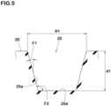
FIG. 5 shows a cross-sectional view of one of thedimples 25. As shown inFIGs. 3 to 5 , each of thedimples 25 has a circular opening, for example. Further, each of thedimples 25 extends in a depth direction thereof while maintaining this opening shape. Thereby, each of thedimples 25 has an inner space having a cylindrical or a truncated cone shape. However, the present invention is not limited to such an embodiment, and the opening shape of each of thedimples 25 may be an ellipse, a triangle, a rectangle, or the like, for example. - As shown in
FIG. 5 , in the present invention, each of thedimples 25 has a maximum diameter A1 of 1 to 5 mm, preferably 2.5 to 4.5 mm. Further, each of thedimples 25 has a maximum depth (d1) of 1 to 3 mm. Therefore, the steering stability and the peeling resistance are improved in a good balance. - Each of the
dimples 25 includes a concave conical portion having a taper angle θ1. The taper angle θ1 is 60 degrees or less, for example, preferably 10 to 30 degrees. It should be noted that the taper angle θ1 is the angle of an inner wall (25a) with respect to the depth direction of each of thedimples 25. Owing to the above taper angle θ1, it is possible that a large volume of each of thedimples 25 is ensured while suppressing cracking of the rubber around thedimples 25. - An angle θ2 between a bottom surface (25d) and the inner wall (25a) is in the range of from 90 to 120 degrees in each of the
dimples 25, for example. Thedimples 25 configured as such exert excellent heat dissipation at the bottom surfaces (25d), therefore, the peeling resistance is further improved. - As shown in
FIG. 4 , it is preferred that thedimples 25 are arranged at an interval (t1) of 2 mm or more and 5 mm or less from each other. Thereby, it is possible that the heat dissipation of thegroove surface 20 of the firstshoulder circumferential groove 11 is increased while the durability thereof is maintained. It should be noted the above interval (t1) corresponds to a distance between the edges of twodimples 25 adjacent immediately to each other. The interval (t1) shown inFIG. 4 indicates the distance between twodimples 25 in the tire circumferential direction, but the above numerical range also applies to the distance in the tire radial direction between twodimples 25 aligned in the tire radial direction. - As shown in
FIG. 2 , the tread rubber (2a) is provided with a plurality of secondshoulder lateral grooves 32 opening at the ground contacting surface (2s) and the first buttresssurface 8A. Each of the secondshoulder lateral grooves 32 in the present embodiment extends with a constant groove width. On the first buttresssurface 8A, a groove width W1 of each of the secondshoulder lateral grooves 32 is 50% or less of a 1-pitch length P2 between each two of the multiple secondshoulder lateral grooves 32 adjacent to each other. In a preferred embodiment, the groove width W1 is in the range from 15% to 30% of the 1-pitch length P2. Therefore, the durability near the first tread edge T1 is improved -
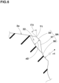
FIG. 6 shows a cross-sectional view taken along A-A line ofFIG. 2 . As shown inFIG. 6 , a maximum depth (d2) of each of the secondshoulder lateral grooves 32 is 50% or less of a maximum depth (da) (shown inFIG. 1 and is the maximum depth not including the dimples 25) of the firstshoulder circumferential groove 11. Thereby, the durability near the first tread edge T1 is further improved. - In the cross section of the tread rubber (2a) passing all through the tire rotational axis, the first buttress
surface 8A includes aninclined surface 35 extending from the first tread edge T1 and aconcave arc surface 36 arranged radially inside theinclined surface 35. Aplane 37 is formed between theinclined surface 35 and theconcave arc surface 36. - The
inclined surface 35 is a plane that slopes axially outward and radially inward from the first tread edge T1. Theinclined surface 35 has an angle θ3 in the range from 40 to 50 degrees with respect to the tire radial direction, for example. Thereby, it is possible that uneven wear around the first tread edge T1 is suppressed. - The
concave arc surface 36 is concave toward the tire equator (C) (shown inFIG. 1 ) and is curved in an arc shape in a cross section thereof. It is possible that theconcave arc surface 36 configured as such effectively suppresses heat generation of the first buttresssurface 8A. From the point of view of improving the durability and the peeling resistance of the first buttresssurface 8A in a good balance, it is preferred that a radius of curvature (r1) of theconcave arc surface 36 is in the range from 20 to 120 mm. - As shown in
FIG. 1 , in the tire 1 of the present embodiment, the configuration on the first tread edge T1 side from the tire equator (C) and the configuration on the second tread edge T2 side from the tire equator (C) are substantially the same. That is, the configuration of the firstshoulder circumferential groove 11 described above can be applied to the second shouldercircumferential groove 12. Further, the configuration of the first buttresssurface 8A can be applied to the second buttresssurface 8B on the opposite side. - The retreaded tire 1 of the present invention can be manufactured by various manufacturing methods. The tire 1 of the present invention may be manufactured by attaching the tread rubber (2a) made of unvulcanized rubber to the base tire (1a) and integrating them by vulcanization molding, for example. In this case, it is preferred that the dimples 25 (shown in
FIGs. 3 to 5 ) are formed by the mold used during the above-mentioned vulcanization molding. In another manufacturing method, the tire 1 of the present invention may be manufactured by, for example, adhering a vulcanized tread rubber (2a) on which the above-mentioneddimples 25 are arranged to the base tire (1a), or after the vulcanized tread rubber (2a) without thedimples 25 is adhered to the base tire (1a), thedimples 25 may be formed on the tread rubber (2a). - While detailed description has been made of the tire according to an embodiment of the present invention, the present invention can be embodied in various forms without being limited to the illustrated embodiment.
- Retreaded tires of size 205/85R16 having the basic structure shown in
FIGs. 1 to 6 were made by way of test according to the specifications listed in Table 1. As Reference, tires not provided with the dimples on the first shoulder circumferential groove were made by way of test. The tires in the Reference were substantially the same as the tires in Examples except for the above-mentioned items. Each of the test tires was tested for the peeling resistance and other damage. The common specifications and test methods for each test tire are as follows. - Tire rim: 16x5.5J
- Tire inner pressure: 600 kPa
- Each of the test tires was placed on a drum testing machine and kept running at a speed of 80 km/h with a vertical load of 16.79 kN, and then the running distance when the retreaded tread peeled off from the base tire was measured. The results are indicated by an index based on the running distance of the Reference being 100, wherein the larger the numerical value, the better the peeling resistance is.
- The test results are shown in Table 1.
Table 1 Ref. Ex. 1 Ex. 2 Ex. 3 Presence (P) or Absence (A) of Dimples in First shoulder circumferential groove A P P P Maximum diameter A1 of Dimple [mm] - 2.5 0.5 0.5 Maximum depth (d1) of Dimple [mm] - 2.5 0.5 0.5 Taper angle θ1 of Dimple [degree] - 30 10 10 Interval (t1) between Dimples [mm] - 2.5 0.5 2.5 Number of Dimples in a radial row on one Groove wall surface in 1-pitch area - 2 7 2 Number of Dimples in a circumferential row on one Groove wall surface in 1-pitch area - 10 1 10 Peeling resistance [index] 100 120 110 110 - As shown in Table 1, from the test results, it was confirmed that the tires in the Examples exerted excellent peeling resistance.
- The present invention includes the following aspects.
- A retreaded tire including:
- a base tire; and
- a tread rubber for retread adhered to the base tire,
- wherein the tread rubber includes a first tread edge and a first shoulder circumferential groove adjacent to the first tread edge and extending continuously in a tire circumferential direction, and
- the first shoulder circumferential groove has a groove surface provided with a plurality of dimples.
- The retreaded tire according to Present Invention 1, wherein
- the groove surface includes a pair of groove wall surfaces, and
- at least one of the groove wall surfaces is provided with the dimples.
- The retreaded tire according to
Present Invention 1 or 2, wherein - the groove surface includes a groove bottom surface, and
- the groove bottom surface is provided with the dimples.
- The retreaded tire according to
Present Invention 1 or 2, wherein - the groove surface includes a pair of groove wall surfaces and a groove bottom surface, and
- at least one of the dimples is formed over the groove bottom surface and one of the groove wall surfaces.
- The retreaded tire according to
Present Invention 1 or 2, wherein each of the dimples has a maximum diameter from 1 to 5 mm and a maximum depth from 1 to 3 mm. - The retreaded tire according to
Present Invention 1 or 2, wherein each of the dimples has a concave conical portion having a taper angle of 60 degrees or less with respect to a depth direction of the each of the dimples. - The retreaded tire according to
Present Invention 1 or 2, wherein the dimples are arranged at an interval from 2 to 5 mm. - The retreaded tire according to
Present Invention 1 or 2, wherein - the groove surface includes a first groove wall surface on the first tread edge side, and
- the first groove wall surface is provided with the dimples.
- The retreaded tire according to
Present Invention 1 or 2, wherein - the first shoulder circumferential groove is connected with a plurality of first shoulder lateral grooves arranged in the tire circumferential direction and each extending in a tire axial direction on a ground contacting surface of the tread rubber, and
- in a 1-pitch area between two first shoulder lateral grooves adjacent to each other, the groove surface is provided with one or more rows each having 2 to 20 dimples arranged in the tire circumferential direction.
- The retreaded tire according to Present Invention 9, wherein
- the groove surface includes a pair of groove wall surfaces, and
- in the 1-pitch area, one of the groove wall surfaces is provided with one or more rows each having 1 to 5 dimples arranged in a tire radial direction.
- The retreaded tire according to
Present Invention 1 or 2, wherein - the tread rubber includes a ground contacting surface extending axially inward from the first tread edge and a first buttress surface extending inward in a tire radial direction from the first tread edge,
- the tread rubber is provided with a plurality of second shoulder lateral grooves each opening at the ground contacting surface and the first buttress surface, and
- on the first buttress surface, each of the second shoulder lateral grooves has a groove width of 50% or less of a 1-pitch length between two second shoulder lateral grooves adjacent to each other.
- The retreaded tire according to
Present Invention 11, wherein each of the second shoulder lateral grooves has a maximum depth of 50% or less of a maximum depth of the first shoulder circumferential groove. - The retreaded tire according to
Present Invention 11, wherein the first buttress surface includes a concave arc surface concave toward a tire equator in a lateral cross section of the tread rubber passing through a tire rotational axis. - The retreaded tire according to
Present Invention 13, wherein the concave arc surface has a radius of curvature of 20 mm or more and 120 mm or less in the lateral cross section. -
- 1a
- base tire
- 2a
- tread rubber
- 11
- first shoulder circumferential groove
- 20
- groove surface
- 25
- dimple
- T1
- first tread edge
Claims (14)
- A retreaded tire comprising:a base tire; anda tread rubber for retread adhered to the base tire,wherein the tread rubber includes a first tread edge and a first shoulder circumferential groove adjacent to the first tread edge and extending continuously in a tire circumferential direction, andthe first shoulder circumferential groove has a groove surface provided with a plurality of dimples.
- The retreaded tire according to claim 1, whereinthe groove surface includes a pair of groove wall surfaces, andat least one of the groove wall surfaces is provided with the dimples.
- The retreaded tire according to claim 1 or 2, whereinthe groove surface includes a groove bottom surface, andthe groove bottom surface is provided with the dimples.
- The retreaded tire according to any one of claims 1 to 3, whereinthe groove surface includes a pair of groove wall surfaces and a groove bottom surface, andat least one of the dimples is formed over the groove bottom surface and one of the groove wall surfaces.
- The retreaded tire according to any one of claims 1 to 4, wherein each of the dimples has a maximum diameter from 1 to 5 mm and a maximum depth from 1 to 3 mm.
- The retreaded tire according to any one of claims 1 to 5, wherein each of the dimples has a concave conical portion having a taper angle of 60 degrees or less with respect to a depth direction of the each of the dimples.
- The retreaded tire according to any one of claims 1 to 6, wherein the dimples are arranged at an interval from 2 to 5 mm.
- The retreaded tire according to any one of claims 1 to 7, whereinthe groove surface includes a first groove wall surface on the first tread edge side, andthe first groove wall surface is provided with the dimples.
- The retreaded tire according to any one of claims 1 to 8, whereinthe first shoulder circumferential groove is connected with a plurality of first shoulder lateral grooves arranged in the tire circumferential direction and each extending in a tire axial direction on a ground contacting surface of the tread rubber, andin a 1-pitch area between two first shoulder lateral grooves adjacent to each other, the groove surface is provided with one or more rows each having 2 to 20 dimples arranged in the tire circumferential direction.
- The retreaded tire according to claim 9, whereinthe groove surface includes a pair of groove wall surfaces, andin the 1-pitch area, one of the groove wall surfaces is provided with one or more rows each having 1 to 5 dimples arranged in a tire radial direction.
- The retreaded tire according to any one of claims 1 to 10, whereinthe tread rubber includes a ground contacting surface extending axially inward from the first tread edge and a first buttress surface extending inward in a tire radial direction from the first tread edge,the tread rubber is provided with a plurality of second shoulder lateral grooves each opening at the ground contacting surface and the first buttress surface, andon the first buttress surface, each of the second shoulder lateral grooves has a groove width of 50% or less of a 1-pitch length between two second shoulder lateral grooves adjacent to each other.
- The retreaded tire according to claim 11, wherein each of the second shoulder lateral grooves has a maximum depth of 50% or less of a maximum depth of the first shoulder circumferential groove.
- The retreaded tire according to claim 11 or 12, wherein the first buttress surface includes a concave arc surface concave toward a tire equator in a lateral cross section of the tread rubber passing through a tire rotational axis.
- The retreaded tire according to claim 13, wherein the concave arc surface has a radius of curvature of 20 mm or more and 120 mm or less in the lateral cross section.
Applications Claiming Priority (1)
| Application Number | Priority Date | Filing Date | Title |
|---|---|---|---|
| JP2022209934A JP2024093506A (en) | 2022-12-27 | 2022-12-27 | Retreaded tires |
Publications (2)
| Publication Number | Publication Date |
|---|---|
| EP4393724A1 true EP4393724A1 (en) | 2024-07-03 |
| EP4393724B1 EP4393724B1 (en) | 2025-06-25 |
Family
ID=88793289
Family Applications (1)
| Application Number | Title | Priority Date | Filing Date |
|---|---|---|---|
| EP23209292.4A Active EP4393724B1 (en) | 2022-12-27 | 2023-11-13 | Retreaded tire |
Country Status (3)
| Country | Link |
|---|---|
| US (1) | US20240208169A1 (en) |
| EP (1) | EP4393724B1 (en) |
| JP (1) | JP2024093506A (en) |
Citations (9)
| Publication number | Priority date | Publication date | Assignee | Title |
|---|---|---|---|---|
| JPH0717217A (en) * | 1993-06-22 | 1995-01-20 | Bridgestone Corp | Pneumatic tire |
| JP2009298184A (en) * | 2008-06-10 | 2009-12-24 | Yokohama Rubber Co Ltd:The | Tread for retreaded tire, and retreaded tire using this |
| JP2011235783A (en) | 2010-05-11 | 2011-11-24 | Sumitomo Rubber Ind Ltd | Retreaded tire, and method of manufacturing the same |
| JP2014019308A (en) * | 2012-07-18 | 2014-02-03 | Yokohama Rubber Co Ltd:The | Precure retreaded tire, precure tread, and method for manufacturing precure retreaded tire |
| JP2014076765A (en) * | 2012-10-11 | 2014-05-01 | Yokohama Rubber Co Ltd:The | Retreaded tire |
| US20140158262A1 (en) * | 2012-12-10 | 2014-06-12 | Toyo Tire & Rubber Co., Ltd. | Pneumatic tire |
| WO2014145894A1 (en) * | 2013-03-15 | 2014-09-18 | Compagnie Generale Des Etablissements | Groove bottom design to allow undertread reduction |
| JP2014213731A (en) * | 2013-04-25 | 2014-11-17 | 東洋ゴム工業株式会社 | Pneumatic tire |
| US20170072749A1 (en) * | 2014-03-10 | 2017-03-16 | Compagnie Generale Des Etablissements Michelin | Tire Including A High-Contrast Texture In A Groove |
Family Cites Families (7)
| Publication number | Priority date | Publication date | Assignee | Title |
|---|---|---|---|---|
| JPS6036304U (en) * | 1983-08-19 | 1985-03-13 | 住友ゴム工業株式会社 | tire tread pattern |
| JPS61102301A (en) * | 1984-10-23 | 1986-05-21 | Bridgestone Corp | Pneumatic type with superior uneven-wear resistant characteristics |
| JP3113388B2 (en) * | 1992-05-25 | 2000-11-27 | 株式会社ブリヂストン | Pneumatic tire |
| US7341082B2 (en) * | 2004-12-28 | 2008-03-11 | The Goodyear Tire & Rubber Company | Shoulder ribs for pneumatic tires |
| JP5254126B2 (en) * | 2008-05-16 | 2013-08-07 | 住友ゴム工業株式会社 | Pneumatic tire |
| US9207150B2 (en) * | 2009-11-25 | 2015-12-08 | Compagnie Generale Des Etablissements Michelin | Tread surface structures for mud evacuation |
| DE102014218662A1 (en) * | 2014-09-17 | 2016-03-31 | Continental Reifen Deutschland Gmbh | Vehicle tires |
-
2022
- 2022-12-27 JP JP2022209934A patent/JP2024093506A/en active Pending
-
2023
- 2023-11-13 EP EP23209292.4A patent/EP4393724B1/en active Active
- 2023-12-11 US US18/534,993 patent/US20240208169A1/en active Pending
Patent Citations (9)
| Publication number | Priority date | Publication date | Assignee | Title |
|---|---|---|---|---|
| JPH0717217A (en) * | 1993-06-22 | 1995-01-20 | Bridgestone Corp | Pneumatic tire |
| JP2009298184A (en) * | 2008-06-10 | 2009-12-24 | Yokohama Rubber Co Ltd:The | Tread for retreaded tire, and retreaded tire using this |
| JP2011235783A (en) | 2010-05-11 | 2011-11-24 | Sumitomo Rubber Ind Ltd | Retreaded tire, and method of manufacturing the same |
| JP2014019308A (en) * | 2012-07-18 | 2014-02-03 | Yokohama Rubber Co Ltd:The | Precure retreaded tire, precure tread, and method for manufacturing precure retreaded tire |
| JP2014076765A (en) * | 2012-10-11 | 2014-05-01 | Yokohama Rubber Co Ltd:The | Retreaded tire |
| US20140158262A1 (en) * | 2012-12-10 | 2014-06-12 | Toyo Tire & Rubber Co., Ltd. | Pneumatic tire |
| WO2014145894A1 (en) * | 2013-03-15 | 2014-09-18 | Compagnie Generale Des Etablissements | Groove bottom design to allow undertread reduction |
| JP2014213731A (en) * | 2013-04-25 | 2014-11-17 | 東洋ゴム工業株式会社 | Pneumatic tire |
| US20170072749A1 (en) * | 2014-03-10 | 2017-03-16 | Compagnie Generale Des Etablissements Michelin | Tire Including A High-Contrast Texture In A Groove |
Also Published As
| Publication number | Publication date |
|---|---|
| US20240208169A1 (en) | 2024-06-27 |
| JP2024093506A (en) | 2024-07-09 |
| EP4393724B1 (en) | 2025-06-25 |
Similar Documents
| Publication | Publication Date | Title |
|---|---|---|
| CN1792621B (en) | Asymmetrical pneumatic run-flat tire | |
| EP3418075A1 (en) | Pneumatic tire | |
| US20040211501A1 (en) | Pneumatic tire | |
| US11413906B2 (en) | Tire | |
| US11548321B2 (en) | Pneumatic tire | |
| US11383559B2 (en) | Pneumatic tire | |
| EP3517321B1 (en) | Tyre | |
| US11046126B2 (en) | Pneumatic tire and method for manufacturing the same | |
| US11104187B2 (en) | Pneumatic tire | |
| EP3501852A1 (en) | Tyre | |
| US10787036B2 (en) | Heavy-duty tire | |
| US10953701B2 (en) | Tire | |
| US11458775B2 (en) | Pneumatic tyre, tyre mold and method for manufacturing pneumatic tyre using the same | |
| EP3437898B1 (en) | Tire | |
| US20170361660A1 (en) | Pneumatic Tire | |
| EP4371787A1 (en) | Retread tire | |
| EP4393724B1 (en) | Retreaded tire | |
| US12623494B2 (en) | Pneumatic tire | |
| US11701927B2 (en) | Pneumatic tire | |
| JP2023092438A (en) | tire | |
| JP7205307B2 (en) | pneumatic tire | |
| EP3925801A1 (en) | Tire | |
| US20230191850A1 (en) | Tire | |
| JP7335485B2 (en) | pneumatic tire | |
| JP2024093430A (en) | Pneumatic tires |
Legal Events
| Date | Code | Title | Description |
|---|---|---|---|
| PUAI | Public reference made under article 153(3) epc to a published international application that has entered the european phase |
Free format text: ORIGINAL CODE: 0009012 |
|
| STAA | Information on the status of an ep patent application or granted ep patent |
Free format text: STATUS: THE APPLICATION HAS BEEN PUBLISHED |
|
| AK | Designated contracting states |
Kind code of ref document: A1 Designated state(s): AL AT BE BG CH CY CZ DE DK EE ES FI FR GB GR HR HU IE IS IT LI LT LU LV MC ME MK MT NL NO PL PT RO RS SE SI SK SM TR |
|
| STAA | Information on the status of an ep patent application or granted ep patent |
Free format text: STATUS: REQUEST FOR EXAMINATION WAS MADE |
|
| 17P | Request for examination filed |
Effective date: 20241118 |
|
| RBV | Designated contracting states (corrected) |
Designated state(s): AL AT BE BG CH CY CZ DE DK EE ES FI FR GB GR HR HU IE IS IT LI LT LU LV MC ME MK MT NL NO PL PT RO RS SE SI SK SM TR |
|
| GRAP | Despatch of communication of intention to grant a patent |
Free format text: ORIGINAL CODE: EPIDOSNIGR1 |
|
| STAA | Information on the status of an ep patent application or granted ep patent |
Free format text: STATUS: GRANT OF PATENT IS INTENDED |
|
| P01 | Opt-out of the competence of the unified patent court (upc) registered |
Free format text: CASE NUMBER: APP_12388/2025 Effective date: 20250313 |
|
| RIC1 | Information provided on ipc code assigned before grant |
Ipc: B60C 11/01 20060101ALI20250318BHEP Ipc: B60C 11/13 20060101ALI20250318BHEP Ipc: B60C 11/02 20060101AFI20250318BHEP |
|
| GRAS | Grant fee paid |
Free format text: ORIGINAL CODE: EPIDOSNIGR3 |
|
| INTG | Intention to grant announced |
Effective date: 20250423 |
|
| RAP3 | Party data changed (applicant data changed or rights of an application transferred) |
Owner name: SUMITOMO RUBBER INDUSTRIES, LTD. |
|
| GRAA | (expected) grant |
Free format text: ORIGINAL CODE: 0009210 |
|
| STAA | Information on the status of an ep patent application or granted ep patent |
Free format text: STATUS: THE PATENT HAS BEEN GRANTED |
|
| AK | Designated contracting states |
Kind code of ref document: B1 Designated state(s): AL AT BE BG CH CY CZ DE DK EE ES FI FR GB GR HR HU IE IS IT LI LT LU LV MC ME MK MT NL NO PL PT RO RS SE SI SK SM TR |
|
| REG | Reference to a national code |
Ref country code: GB Ref legal event code: FG4D |
|
| REG | Reference to a national code |
Ref country code: CH Ref legal event code: EP |
|
| REG | Reference to a national code |
Ref country code: DE Ref legal event code: R096 Ref document number: 602023004301 Country of ref document: DE |
|
| REG | Reference to a national code |
Ref country code: CH Ref legal event code: EP |
|
| REG | Reference to a national code |
Ref country code: IE Ref legal event code: FG4D |
|
| PG25 | Lapsed in a contracting state [announced via postgrant information from national office to epo] |
Ref country code: FI Free format text: LAPSE BECAUSE OF FAILURE TO SUBMIT A TRANSLATION OF THE DESCRIPTION OR TO PAY THE FEE WITHIN THE PRESCRIBED TIME-LIMIT Effective date: 20250625 |
|
| REG | Reference to a national code |
Ref country code: LT Ref legal event code: MG9D |
|
| PG25 | Lapsed in a contracting state [announced via postgrant information from national office to epo] |
Ref country code: NO Free format text: LAPSE BECAUSE OF FAILURE TO SUBMIT A TRANSLATION OF THE DESCRIPTION OR TO PAY THE FEE WITHIN THE PRESCRIBED TIME-LIMIT Effective date: 20250925 Ref country code: GR Free format text: LAPSE BECAUSE OF FAILURE TO SUBMIT A TRANSLATION OF THE DESCRIPTION OR TO PAY THE FEE WITHIN THE PRESCRIBED TIME-LIMIT Effective date: 20250926 |
|
| PG25 | Lapsed in a contracting state [announced via postgrant information from national office to epo] |
Ref country code: BG Free format text: LAPSE BECAUSE OF FAILURE TO SUBMIT A TRANSLATION OF THE DESCRIPTION OR TO PAY THE FEE WITHIN THE PRESCRIBED TIME-LIMIT Effective date: 20250625 |
|
| PG25 | Lapsed in a contracting state [announced via postgrant information from national office to epo] |
Ref country code: HR Free format text: LAPSE BECAUSE OF FAILURE TO SUBMIT A TRANSLATION OF THE DESCRIPTION OR TO PAY THE FEE WITHIN THE PRESCRIBED TIME-LIMIT Effective date: 20250625 |
|
| PG25 | Lapsed in a contracting state [announced via postgrant information from national office to epo] |
Ref country code: RS Free format text: LAPSE BECAUSE OF FAILURE TO SUBMIT A TRANSLATION OF THE DESCRIPTION OR TO PAY THE FEE WITHIN THE PRESCRIBED TIME-LIMIT Effective date: 20250925 |
|
| PG25 | Lapsed in a contracting state [announced via postgrant information from national office to epo] |
Ref country code: LV Free format text: LAPSE BECAUSE OF FAILURE TO SUBMIT A TRANSLATION OF THE DESCRIPTION OR TO PAY THE FEE WITHIN THE PRESCRIBED TIME-LIMIT Effective date: 20250625 |
|
| REG | Reference to a national code |
Ref country code: NL Ref legal event code: MP Effective date: 20250625 |
|
| PG25 | Lapsed in a contracting state [announced via postgrant information from national office to epo] |
Ref country code: NL Free format text: LAPSE BECAUSE OF FAILURE TO SUBMIT A TRANSLATION OF THE DESCRIPTION OR TO PAY THE FEE WITHIN THE PRESCRIBED TIME-LIMIT Effective date: 20250625 |
|
| PG25 | Lapsed in a contracting state [announced via postgrant information from national office to epo] |
Ref country code: PT Free format text: LAPSE BECAUSE OF FAILURE TO SUBMIT A TRANSLATION OF THE DESCRIPTION OR TO PAY THE FEE WITHIN THE PRESCRIBED TIME-LIMIT Effective date: 20251027 |
|
| REG | Reference to a national code |
Ref country code: AT Ref legal event code: MK05 Ref document number: 1806119 Country of ref document: AT Kind code of ref document: T Effective date: 20250625 |
|
| PG25 | Lapsed in a contracting state [announced via postgrant information from national office to epo] |
Ref country code: IS Free format text: LAPSE BECAUSE OF FAILURE TO SUBMIT A TRANSLATION OF THE DESCRIPTION OR TO PAY THE FEE WITHIN THE PRESCRIBED TIME-LIMIT Effective date: 20251025 |
|
| PG25 | Lapsed in a contracting state [announced via postgrant information from national office to epo] |
Ref country code: AT Free format text: LAPSE BECAUSE OF FAILURE TO SUBMIT A TRANSLATION OF THE DESCRIPTION OR TO PAY THE FEE WITHIN THE PRESCRIBED TIME-LIMIT Effective date: 20250625 Ref country code: SM Free format text: LAPSE BECAUSE OF FAILURE TO SUBMIT A TRANSLATION OF THE DESCRIPTION OR TO PAY THE FEE WITHIN THE PRESCRIBED TIME-LIMIT Effective date: 20250625 |
|
| PGFP | Annual fee paid to national office [announced via postgrant information from national office to epo] |
Ref country code: FR Payment date: 20251126 Year of fee payment: 3 |
|
| PG25 | Lapsed in a contracting state [announced via postgrant information from national office to epo] |
Ref country code: CZ Free format text: LAPSE BECAUSE OF FAILURE TO SUBMIT A TRANSLATION OF THE DESCRIPTION OR TO PAY THE FEE WITHIN THE PRESCRIBED TIME-LIMIT Effective date: 20250625 |
|
| PG25 | Lapsed in a contracting state [announced via postgrant information from national office to epo] |
Ref country code: PL Free format text: LAPSE BECAUSE OF FAILURE TO SUBMIT A TRANSLATION OF THE DESCRIPTION OR TO PAY THE FEE WITHIN THE PRESCRIBED TIME-LIMIT Effective date: 20250625 |
|
| PG25 | Lapsed in a contracting state [announced via postgrant information from national office to epo] |
Ref country code: EE Free format text: LAPSE BECAUSE OF FAILURE TO SUBMIT A TRANSLATION OF THE DESCRIPTION OR TO PAY THE FEE WITHIN THE PRESCRIBED TIME-LIMIT Effective date: 20250625 |
|
| PG25 | Lapsed in a contracting state [announced via postgrant information from national office to epo] |
Ref country code: SK Free format text: LAPSE BECAUSE OF FAILURE TO SUBMIT A TRANSLATION OF THE DESCRIPTION OR TO PAY THE FEE WITHIN THE PRESCRIBED TIME-LIMIT Effective date: 20250625 |
|
| PG25 | Lapsed in a contracting state [announced via postgrant information from national office to epo] |
Ref country code: ES Free format text: LAPSE BECAUSE OF FAILURE TO SUBMIT A TRANSLATION OF THE DESCRIPTION OR TO PAY THE FEE WITHIN THE PRESCRIBED TIME-LIMIT Effective date: 20250625 |
|
| PG25 | Lapsed in a contracting state [announced via postgrant information from national office to epo] |
Ref country code: RO Free format text: LAPSE BECAUSE OF FAILURE TO SUBMIT A TRANSLATION OF THE DESCRIPTION OR TO PAY THE FEE WITHIN THE PRESCRIBED TIME-LIMIT Effective date: 20250625 |
|
| PG25 | Lapsed in a contracting state [announced via postgrant information from national office to epo] |
Ref country code: DK Free format text: LAPSE BECAUSE OF FAILURE TO SUBMIT A TRANSLATION OF THE DESCRIPTION OR TO PAY THE FEE WITHIN THE PRESCRIBED TIME-LIMIT Effective date: 20250625 |
|
| PGFP | Annual fee paid to national office [announced via postgrant information from national office to epo] |
Ref country code: DE Payment date: 20260128 Year of fee payment: 3 |
|
| PG25 | Lapsed in a contracting state [announced via postgrant information from national office to epo] |
Ref country code: IT Free format text: LAPSE BECAUSE OF FAILURE TO SUBMIT A TRANSLATION OF THE DESCRIPTION OR TO PAY THE FEE WITHIN THE PRESCRIBED TIME-LIMIT Effective date: 20250625 |
|
| PLBE | No opposition filed within time limit |
Free format text: ORIGINAL CODE: 0009261 |
|
| STAA | Information on the status of an ep patent application or granted ep patent |
Free format text: STATUS: NO OPPOSITION FILED WITHIN TIME LIMIT |
|
| REG | Reference to a national code |
Ref country code: CH Ref legal event code: L10 Free format text: ST27 STATUS EVENT CODE: U-0-0-L10-L00 (AS PROVIDED BY THE NATIONAL OFFICE) Effective date: 20260507 |