EP4393712A1 - Liquid ejection head - Google Patents
Liquid ejection head Download PDFInfo
- Publication number
- EP4393712A1 EP4393712A1 EP23216622.3A EP23216622A EP4393712A1 EP 4393712 A1 EP4393712 A1 EP 4393712A1 EP 23216622 A EP23216622 A EP 23216622A EP 4393712 A1 EP4393712 A1 EP 4393712A1
- Authority
- EP
- European Patent Office
- Prior art keywords
- ejection
- liquid
- head according
- ejection head
- liquid ejection
- Prior art date
- Legal status (The legal status is an assumption and is not a legal conclusion. Google has not performed a legal analysis and makes no representation as to the accuracy of the status listed.)
- Pending
Links
- 239000007788 liquid Substances 0.000 title claims abstract description 239
- 238000007639 printing Methods 0.000 claims abstract description 138
- 239000000758 substrate Substances 0.000 claims abstract description 120
- 239000000853 adhesive Substances 0.000 claims abstract description 79
- 230000001070 adhesive effect Effects 0.000 claims abstract description 79
- 230000001681 protective effect Effects 0.000 claims abstract description 79
- 239000000463 material Substances 0.000 claims description 26
- 239000011347 resin Substances 0.000 claims description 7
- 229920005989 resin Polymers 0.000 claims description 7
- 229910052751 metal Inorganic materials 0.000 claims description 3
- 239000002184 metal Substances 0.000 claims description 3
- 229910001220 stainless steel Inorganic materials 0.000 claims description 2
- 239000010935 stainless steel Substances 0.000 claims description 2
- 230000001154 acute effect Effects 0.000 claims 1
- 238000003491 array Methods 0.000 description 42
- 238000004891 communication Methods 0.000 description 20
- 230000007246 mechanism Effects 0.000 description 18
- 230000004048 modification Effects 0.000 description 14
- 238000012986 modification Methods 0.000 description 14
- 238000004140 cleaning Methods 0.000 description 9
- 238000007641 inkjet printing Methods 0.000 description 7
- 238000000034 method Methods 0.000 description 7
- 238000010586 diagram Methods 0.000 description 5
- 229920001187 thermosetting polymer Polymers 0.000 description 5
- XUIMIQQOPSSXEZ-UHFFFAOYSA-N Silicon Chemical compound [Si] XUIMIQQOPSSXEZ-UHFFFAOYSA-N 0.000 description 4
- PNEYBMLMFCGWSK-UHFFFAOYSA-N aluminium oxide Inorganic materials [O-2].[O-2].[O-2].[Al+3].[Al+3] PNEYBMLMFCGWSK-UHFFFAOYSA-N 0.000 description 4
- 238000003672 processing method Methods 0.000 description 4
- 229910052710 silicon Inorganic materials 0.000 description 4
- 239000010703 silicon Substances 0.000 description 4
- 230000000694 effects Effects 0.000 description 3
- 238000005530 etching Methods 0.000 description 3
- 238000005304 joining Methods 0.000 description 3
- 230000002940 repellent Effects 0.000 description 3
- 239000005871 repellent Substances 0.000 description 3
- 230000008719 thickening Effects 0.000 description 3
- XLYOFNOQVPJJNP-UHFFFAOYSA-N water Substances O XLYOFNOQVPJJNP-UHFFFAOYSA-N 0.000 description 3
- 229920000106 Liquid crystal polymer Polymers 0.000 description 2
- 239000004977 Liquid-crystal polymers (LCPs) Substances 0.000 description 2
- VYPSYNLAJGMNEJ-UHFFFAOYSA-N Silicium dioxide Chemical compound O=[Si]=O VYPSYNLAJGMNEJ-UHFFFAOYSA-N 0.000 description 2
- 230000009471 action Effects 0.000 description 2
- 229910052782 aluminium Inorganic materials 0.000 description 2
- XAGFODPZIPBFFR-UHFFFAOYSA-N aluminium Chemical compound [Al] XAGFODPZIPBFFR-UHFFFAOYSA-N 0.000 description 2
- 239000000919 ceramic Substances 0.000 description 2
- 230000008859 change Effects 0.000 description 2
- 239000003086 colorant Substances 0.000 description 2
- 230000007797 corrosion Effects 0.000 description 2
- 238000005260 corrosion Methods 0.000 description 2
- 238000006073 displacement reaction Methods 0.000 description 2
- 238000010438 heat treatment Methods 0.000 description 2
- 238000012423 maintenance Methods 0.000 description 2
- 239000007769 metal material Substances 0.000 description 2
- 229920002492 poly(sulfone) Polymers 0.000 description 2
- 229920001955 polyphenylene ether Polymers 0.000 description 2
- 230000008569 process Effects 0.000 description 2
- 238000011084 recovery Methods 0.000 description 2
- 239000003566 sealing material Substances 0.000 description 2
- 238000011144 upstream manufacturing Methods 0.000 description 2
- UCKMPCXJQFINFW-UHFFFAOYSA-N Sulphide Chemical compound [S-2] UCKMPCXJQFINFW-UHFFFAOYSA-N 0.000 description 1
- 230000015572 biosynthetic process Effects 0.000 description 1
- 238000009835 boiling Methods 0.000 description 1
- 230000005587 bubbling Effects 0.000 description 1
- 239000002131 composite material Substances 0.000 description 1
- 239000000805 composite resin Substances 0.000 description 1
- 238000007599 discharging Methods 0.000 description 1
- 239000000428 dust Substances 0.000 description 1
- 238000001704 evaporation Methods 0.000 description 1
- 230000008020 evaporation Effects 0.000 description 1
- 239000000835 fiber Substances 0.000 description 1
- 239000000945 filler Substances 0.000 description 1
- 239000010419 fine particle Substances 0.000 description 1
- 238000007667 floating Methods 0.000 description 1
- 239000011521 glass Substances 0.000 description 1
- 239000011256 inorganic filler Substances 0.000 description 1
- 229910003475 inorganic filler Inorganic materials 0.000 description 1
- 238000003754 machining Methods 0.000 description 1
- 238000004519 manufacturing process Methods 0.000 description 1
- 238000005192 partition Methods 0.000 description 1
- 238000000206 photolithography Methods 0.000 description 1
- 229920006389 polyphenyl polymer Polymers 0.000 description 1
- 238000012545 processing Methods 0.000 description 1
- 239000000377 silicon dioxide Substances 0.000 description 1
- 238000003466 welding Methods 0.000 description 1
Images











Classifications
-
- B—PERFORMING OPERATIONS; TRANSPORTING
- B41—PRINTING; LINING MACHINES; TYPEWRITERS; STAMPS
- B41J—TYPEWRITERS; SELECTIVE PRINTING MECHANISMS, i.e. MECHANISMS PRINTING OTHERWISE THAN FROM A FORME; CORRECTION OF TYPOGRAPHICAL ERRORS
- B41J2/00—Typewriters or selective printing mechanisms characterised by the printing or marking process for which they are designed
- B41J2/005—Typewriters or selective printing mechanisms characterised by the printing or marking process for which they are designed characterised by bringing liquid or particles selectively into contact with a printing material
- B41J2/01—Ink jet
- B41J2/135—Nozzles
- B41J2/14—Structure thereof only for on-demand ink jet heads
- B41J2/14016—Structure of bubble jet print heads
- B41J2/14024—Assembling head parts
-
- B—PERFORMING OPERATIONS; TRANSPORTING
- B41—PRINTING; LINING MACHINES; TYPEWRITERS; STAMPS
- B41J—TYPEWRITERS; SELECTIVE PRINTING MECHANISMS, i.e. MECHANISMS PRINTING OTHERWISE THAN FROM A FORME; CORRECTION OF TYPOGRAPHICAL ERRORS
- B41J2/00—Typewriters or selective printing mechanisms characterised by the printing or marking process for which they are designed
- B41J2/005—Typewriters or selective printing mechanisms characterised by the printing or marking process for which they are designed characterised by bringing liquid or particles selectively into contact with a printing material
- B41J2/01—Ink jet
- B41J2/135—Nozzles
- B41J2/14—Structure thereof only for on-demand ink jet heads
- B41J2/14016—Structure of bubble jet print heads
- B41J2/14032—Structure of the pressure chamber
-
- B—PERFORMING OPERATIONS; TRANSPORTING
- B41—PRINTING; LINING MACHINES; TYPEWRITERS; STAMPS
- B41J—TYPEWRITERS; SELECTIVE PRINTING MECHANISMS, i.e. MECHANISMS PRINTING OTHERWISE THAN FROM A FORME; CORRECTION OF TYPOGRAPHICAL ERRORS
- B41J2/00—Typewriters or selective printing mechanisms characterised by the printing or marking process for which they are designed
- B41J2/005—Typewriters or selective printing mechanisms characterised by the printing or marking process for which they are designed characterised by bringing liquid or particles selectively into contact with a printing material
- B41J2/01—Ink jet
- B41J2/135—Nozzles
- B41J2/14—Structure thereof only for on-demand ink jet heads
- B41J2/14016—Structure of bubble jet print heads
- B41J2/14032—Structure of the pressure chamber
- B41J2/1404—Geometrical characteristics
-
- B—PERFORMING OPERATIONS; TRANSPORTING
- B41—PRINTING; LINING MACHINES; TYPEWRITERS; STAMPS
- B41J—TYPEWRITERS; SELECTIVE PRINTING MECHANISMS, i.e. MECHANISMS PRINTING OTHERWISE THAN FROM A FORME; CORRECTION OF TYPOGRAPHICAL ERRORS
- B41J2/00—Typewriters or selective printing mechanisms characterised by the printing or marking process for which they are designed
- B41J2/005—Typewriters or selective printing mechanisms characterised by the printing or marking process for which they are designed characterised by bringing liquid or particles selectively into contact with a printing material
- B41J2/01—Ink jet
- B41J2/135—Nozzles
- B41J2/14—Structure thereof only for on-demand ink jet heads
- B41J2/14016—Structure of bubble jet print heads
- B41J2/14145—Structure of the manifold
-
- B—PERFORMING OPERATIONS; TRANSPORTING
- B41—PRINTING; LINING MACHINES; TYPEWRITERS; STAMPS
- B41J—TYPEWRITERS; SELECTIVE PRINTING MECHANISMS, i.e. MECHANISMS PRINTING OTHERWISE THAN FROM A FORME; CORRECTION OF TYPOGRAPHICAL ERRORS
- B41J2/00—Typewriters or selective printing mechanisms characterised by the printing or marking process for which they are designed
- B41J2/005—Typewriters or selective printing mechanisms characterised by the printing or marking process for which they are designed characterised by bringing liquid or particles selectively into contact with a printing material
- B41J2/01—Ink jet
- B41J2/135—Nozzles
- B41J2/145—Arrangement thereof
- B41J2/155—Arrangement thereof for line printing
-
- B—PERFORMING OPERATIONS; TRANSPORTING
- B41—PRINTING; LINING MACHINES; TYPEWRITERS; STAMPS
- B41J—TYPEWRITERS; SELECTIVE PRINTING MECHANISMS, i.e. MECHANISMS PRINTING OTHERWISE THAN FROM A FORME; CORRECTION OF TYPOGRAPHICAL ERRORS
- B41J2/00—Typewriters or selective printing mechanisms characterised by the printing or marking process for which they are designed
- B41J2/005—Typewriters or selective printing mechanisms characterised by the printing or marking process for which they are designed characterised by bringing liquid or particles selectively into contact with a printing material
- B41J2/01—Ink jet
- B41J2/135—Nozzles
- B41J2/16—Production of nozzles
- B41J2/1601—Production of bubble jet print heads
-
- B—PERFORMING OPERATIONS; TRANSPORTING
- B41—PRINTING; LINING MACHINES; TYPEWRITERS; STAMPS
- B41J—TYPEWRITERS; SELECTIVE PRINTING MECHANISMS, i.e. MECHANISMS PRINTING OTHERWISE THAN FROM A FORME; CORRECTION OF TYPOGRAPHICAL ERRORS
- B41J2/00—Typewriters or selective printing mechanisms characterised by the printing or marking process for which they are designed
- B41J2/005—Typewriters or selective printing mechanisms characterised by the printing or marking process for which they are designed characterised by bringing liquid or particles selectively into contact with a printing material
- B41J2/01—Ink jet
- B41J2/135—Nozzles
- B41J2/16—Production of nozzles
- B41J2/1601—Production of bubble jet print heads
- B41J2/1603—Production of bubble jet print heads of the front shooter type
-
- B—PERFORMING OPERATIONS; TRANSPORTING
- B41—PRINTING; LINING MACHINES; TYPEWRITERS; STAMPS
- B41J—TYPEWRITERS; SELECTIVE PRINTING MECHANISMS, i.e. MECHANISMS PRINTING OTHERWISE THAN FROM A FORME; CORRECTION OF TYPOGRAPHICAL ERRORS
- B41J2/00—Typewriters or selective printing mechanisms characterised by the printing or marking process for which they are designed
- B41J2/005—Typewriters or selective printing mechanisms characterised by the printing or marking process for which they are designed characterised by bringing liquid or particles selectively into contact with a printing material
- B41J2/01—Ink jet
- B41J2/135—Nozzles
- B41J2/16—Production of nozzles
- B41J2/1621—Manufacturing processes
- B41J2/1623—Manufacturing processes bonding and adhesion
-
- B—PERFORMING OPERATIONS; TRANSPORTING
- B41—PRINTING; LINING MACHINES; TYPEWRITERS; STAMPS
- B41J—TYPEWRITERS; SELECTIVE PRINTING MECHANISMS, i.e. MECHANISMS PRINTING OTHERWISE THAN FROM A FORME; CORRECTION OF TYPOGRAPHICAL ERRORS
- B41J2/00—Typewriters or selective printing mechanisms characterised by the printing or marking process for which they are designed
- B41J2/005—Typewriters or selective printing mechanisms characterised by the printing or marking process for which they are designed characterised by bringing liquid or particles selectively into contact with a printing material
- B41J2/01—Ink jet
- B41J2/135—Nozzles
- B41J2/16—Production of nozzles
- B41J2/1621—Manufacturing processes
- B41J2/1626—Manufacturing processes etching
-
- B—PERFORMING OPERATIONS; TRANSPORTING
- B41—PRINTING; LINING MACHINES; TYPEWRITERS; STAMPS
- B41J—TYPEWRITERS; SELECTIVE PRINTING MECHANISMS, i.e. MECHANISMS PRINTING OTHERWISE THAN FROM A FORME; CORRECTION OF TYPOGRAPHICAL ERRORS
- B41J2/00—Typewriters or selective printing mechanisms characterised by the printing or marking process for which they are designed
- B41J2/005—Typewriters or selective printing mechanisms characterised by the printing or marking process for which they are designed characterised by bringing liquid or particles selectively into contact with a printing material
- B41J2/01—Ink jet
- B41J2/135—Nozzles
- B41J2/16—Production of nozzles
- B41J2/1621—Manufacturing processes
- B41J2/1631—Manufacturing processes photolithography
-
- B—PERFORMING OPERATIONS; TRANSPORTING
- B41—PRINTING; LINING MACHINES; TYPEWRITERS; STAMPS
- B41J—TYPEWRITERS; SELECTIVE PRINTING MECHANISMS, i.e. MECHANISMS PRINTING OTHERWISE THAN FROM A FORME; CORRECTION OF TYPOGRAPHICAL ERRORS
- B41J2/00—Typewriters or selective printing mechanisms characterised by the printing or marking process for which they are designed
- B41J2/005—Typewriters or selective printing mechanisms characterised by the printing or marking process for which they are designed characterised by bringing liquid or particles selectively into contact with a printing material
- B41J2/01—Ink jet
- B41J2/135—Nozzles
- B41J2/16—Production of nozzles
- B41J2/1621—Manufacturing processes
- B41J2/1632—Manufacturing processes machining
-
- B—PERFORMING OPERATIONS; TRANSPORTING
- B41—PRINTING; LINING MACHINES; TYPEWRITERS; STAMPS
- B41J—TYPEWRITERS; SELECTIVE PRINTING MECHANISMS, i.e. MECHANISMS PRINTING OTHERWISE THAN FROM A FORME; CORRECTION OF TYPOGRAPHICAL ERRORS
- B41J2/00—Typewriters or selective printing mechanisms characterised by the printing or marking process for which they are designed
- B41J2/005—Typewriters or selective printing mechanisms characterised by the printing or marking process for which they are designed characterised by bringing liquid or particles selectively into contact with a printing material
- B41J2/01—Ink jet
- B41J2/135—Nozzles
- B41J2/16—Production of nozzles
- B41J2/1621—Manufacturing processes
- B41J2/1632—Manufacturing processes machining
- B41J2/1634—Manufacturing processes machining laser machining
-
- B—PERFORMING OPERATIONS; TRANSPORTING
- B41—PRINTING; LINING MACHINES; TYPEWRITERS; STAMPS
- B41J—TYPEWRITERS; SELECTIVE PRINTING MECHANISMS, i.e. MECHANISMS PRINTING OTHERWISE THAN FROM A FORME; CORRECTION OF TYPOGRAPHICAL ERRORS
- B41J2/00—Typewriters or selective printing mechanisms characterised by the printing or marking process for which they are designed
- B41J2/005—Typewriters or selective printing mechanisms characterised by the printing or marking process for which they are designed characterised by bringing liquid or particles selectively into contact with a printing material
- B41J2/01—Ink jet
- B41J2/17—Ink jet characterised by ink handling
- B41J2/175—Ink supply systems ; Circuit parts therefor
- B41J2/17596—Ink pumps, ink valves
-
- B—PERFORMING OPERATIONS; TRANSPORTING
- B41—PRINTING; LINING MACHINES; TYPEWRITERS; STAMPS
- B41J—TYPEWRITERS; SELECTIVE PRINTING MECHANISMS, i.e. MECHANISMS PRINTING OTHERWISE THAN FROM A FORME; CORRECTION OF TYPOGRAPHICAL ERRORS
- B41J2/00—Typewriters or selective printing mechanisms characterised by the printing or marking process for which they are designed
- B41J2/005—Typewriters or selective printing mechanisms characterised by the printing or marking process for which they are designed characterised by bringing liquid or particles selectively into contact with a printing material
- B41J2/01—Ink jet
- B41J2/17—Ink jet characterised by ink handling
- B41J2/18—Ink recirculation systems
-
- B—PERFORMING OPERATIONS; TRANSPORTING
- B41—PRINTING; LINING MACHINES; TYPEWRITERS; STAMPS
- B41J—TYPEWRITERS; SELECTIVE PRINTING MECHANISMS, i.e. MECHANISMS PRINTING OTHERWISE THAN FROM A FORME; CORRECTION OF TYPOGRAPHICAL ERRORS
- B41J2/00—Typewriters or selective printing mechanisms characterised by the printing or marking process for which they are designed
- B41J2/005—Typewriters or selective printing mechanisms characterised by the printing or marking process for which they are designed characterised by bringing liquid or particles selectively into contact with a printing material
- B41J2/01—Ink jet
- B41J2/135—Nozzles
- B41J2/14—Structure thereof only for on-demand ink jet heads
- B41J2002/14411—Groove in the nozzle plate
-
- B—PERFORMING OPERATIONS; TRANSPORTING
- B41—PRINTING; LINING MACHINES; TYPEWRITERS; STAMPS
- B41J—TYPEWRITERS; SELECTIVE PRINTING MECHANISMS, i.e. MECHANISMS PRINTING OTHERWISE THAN FROM A FORME; CORRECTION OF TYPOGRAPHICAL ERRORS
- B41J2202/00—Embodiments of or processes related to ink-jet or thermal heads
- B41J2202/01—Embodiments of or processes related to ink-jet heads
- B41J2202/12—Embodiments of or processes related to ink-jet heads with ink circulating through the whole print head
-
- B—PERFORMING OPERATIONS; TRANSPORTING
- B41—PRINTING; LINING MACHINES; TYPEWRITERS; STAMPS
- B41J—TYPEWRITERS; SELECTIVE PRINTING MECHANISMS, i.e. MECHANISMS PRINTING OTHERWISE THAN FROM A FORME; CORRECTION OF TYPOGRAPHICAL ERRORS
- B41J2202/00—Embodiments of or processes related to ink-jet or thermal heads
- B41J2202/01—Embodiments of or processes related to ink-jet heads
- B41J2202/19—Assembling head units
-
- B—PERFORMING OPERATIONS; TRANSPORTING
- B41—PRINTING; LINING MACHINES; TYPEWRITERS; STAMPS
- B41J—TYPEWRITERS; SELECTIVE PRINTING MECHANISMS, i.e. MECHANISMS PRINTING OTHERWISE THAN FROM A FORME; CORRECTION OF TYPOGRAPHICAL ERRORS
- B41J2202/00—Embodiments of or processes related to ink-jet or thermal heads
- B41J2202/01—Embodiments of or processes related to ink-jet heads
- B41J2202/20—Modules
Definitions
- Line liquid ejection apparatuses which perform high-speed printing using a liquid ejection head corresponding to a width of a printed medium on which a plurality of printing element substrates are arranged.
- a printed medium being conveyed may float upward and come into contact with a printing element substrate and damage the liquid ejection head.
- Literature 1 Japanese Patent Laid-Open No. 2006-334910
- Literature 2 Japanese Patent Laid-Open No. H4-234665
- the present embodiments represent an inkjet printing apparatus (printing apparatus) formed so as to circulate a liquid such as ink between a tank and a liquid ejection head
- the inkjet printing apparatus may be given other forms.
- the inkjet printing apparatus may be provided with two tanks, respectively, on an upstream side and a downstream side of a liquid ejection head and may be formed to cause ink inside a pressure chamber to flow by supplying the ink from one tank to the other tank.
- the present embodiments represent a so-called line head having a length corresponding to a width of a printed medium
- the present disclosure can also be applied to a so-called serial liquid ejection head which performs printing while scanning a printed medium.
- An example of a serial liquid ejection head is a configuration which is respectively mounted with one printing element substrate for black ink and one printing element substrate for color ink.
- the liquid ejection head according to the present disclosure is not limited thereto and may be formed so as to create a short line head which is shorter than a width of a printed medium and in which several printing element substrates are arranged so that ejection orifices overlap with each other in an ejection orifice array direction and to scan the printed medium with the short line head.
- FIG. 1 shows a schematic configuration of an apparatus which ejects a liquid or, more particularly, an inkjet printing apparatus 1000 (hereinafter, also referred to as a printing apparatus) which performs printing by ejecting ink according to the present disclosure.
- the printing apparatus 1000 is a line printing apparatus which includes a conveying section 1 which conveys a printed medium 2 and a line liquid ejection head 3 which is arranged approximately orthogonal to a conveying direction of the printed medium and which performs continuous single-pass printing while continuously or intermittently conveying a plurality of printed media 2.
- the printed medium 2 is not limited to cut paper and may be continuous rolled paper.
- the liquid ejection head 3 is capable of full-color (cyan, magenta, yellow, and black) printing using CMYK ink.
- liquid supplying means which is a supply path for supplying a liquid to the liquid ejection head, a main tank, and a buffer tank (refer to FIG. 2 ) are fluidically connected to the liquid ejection head 3.
- an electric control section which transmits power and ejection control signals to the liquid ejection head 3 is electrically connected to the liquid ejection head 3. A liquid path and an electric signal path in the liquid ejection head 3 will be described later.
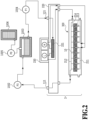
- FIG. 2 is a schematic view showing a circulation path applied to the printing apparatus according to the present disclosure in which the liquid ejection head 3 is fluidically connected to a first circulating pump 1002, a buffer tank 1003, and the like. Note that FIG. 2 only shows a path by which an ink of one color among CMYK ink flows for the sake of brevity.
- the buffer tank 1003 as a sub-tank to be connected to a main tank 1006 includes an air communication port (not illustrated) which communicates the inside of the tank to the outside and is capable of discharging bubbles inside the ink to the outside.
- the buffer tank 1003 is also connected to a replenishing pump 1005.
- the replenishing pump 1005 transfers ink corresponding to a consumed amount from the main tank 1006 to the buffer tank 1003.
- the first circulating pump 1002 has a role of extracting a liquid from a liquid connecting part 111 of the liquid ejection head 3 and feeding the liquid to the buffer tank 1003.
- a displacement pump with a quantitative liquid feeding capability is preferably used as the first circulating pump 1002. While specific examples include a tube pump, a gear pump, a diaphragm pump, a syringe pump, and the like, for example, even a form of arranging a general constant-flow valve or a relief valve at a pump outlet to secure a constant flow rate can be adopted.
- the first circulating pump 1002 causes a certain amount of ink to flow inside a common collection flow path 212.
- a flow rate of the ink is preferably set to or above a level at which a temperature difference between respective printing element substrates 10 inside the liquid ejection head 3 does not affect printing image quality.
- setting an excessively large flow rate results in excessive negative pressure between the respective printing element substrates 10 due to an effect of a pressure drop of a flow path inside a liquid ejection unit 300 and unevenness in density is created in an image. Therefore, the flow rate is preferably set while taking a temperature difference and a negative pressure difference between the respective printing element substrates 10 into consideration.
- a negative pressure control unit 230 is provided between paths connecting a second circulating pump 1004 and the liquid ejection unit 300 to each other. Therefore, the negative pressure control unit 230 has a function of operating so as to maintain pressure on a downstream side of the negative pressure control unit 230 (in other words, the side of the liquid ejection unit 300) at constant pressure set in advance even when a flow rate of a circulation system fluctuates due to a difference in duties of performing printing.
- any mechanism may be used as long as the mechanism is capable of controlling pressure on a downstream side of the mechanism itself to a fluctuation within or below a certain range centered on desired set pressure.
- a mechanism similar to a so-called "pressure-reducing regulator” can be used.
- pressure is preferably applied by the second circulating pump 1004 to an upstream side of the negative pressure control unit 230 via a liquid supply unit 220.
- the second circulating pump 1004 need only have pump head pressure of certain pressure or higher within a range of an ink circulation flow rate used when driving the liquid ejection head 3 and a turbo pump, a displacement pump, or the like can be used.
- a diaphragm pump or the like can be applied.
- a water head tank arranged with a certain water head difference with respect to the negative pressure control unit 230 can also be applied instead of the second circulating pump 1004.
- the negative pressure control unit 230 includes two pressure adjustment mechanisms respectively set to mutually different control pressure.
- a side set to relatively high pressure (denoted by H in FIG. 2 ) and a side set to relatively low pressure (denoted by L in FIG. 2 ) are respectively connected to a common supply flow path 211 and a common collection flow path 212 in the liquid ejection unit 300 via the liquid supply unit 220.
- the liquid ejection unit 300 is provided with the common supply flow path 211, the common collection flow path 212, and an individual supply flow path 213 and an individual collection flow path 214 which communicate with each printing element substrate.
- the individual supply flow path 213 and the individual collection flow path 214 are respectively communicated with the common supply flow path 211 and the common collection flow path 212. Accordingly, a part of the liquid fed by the first circulating pump 1002 passes through an internal flow path of the printing element substrate 10 from the common supply flow path 211 and flows into the common collection flow path 212 (arrow in FIG. 2 ). This is because a pressure difference is provided between the pressure adjustment mechanism H connected to the common supply flow path 211 and the pressure adjustment mechanism L connected to the common collection flow path 212 and the first circulating pump 1002 is only connected to the common collection flow path 212.
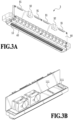
- FIG. 3A and FIG. 3B are perspective views of the liquid ejection head 3 according to the present embodiment.
- the liquid ejection head 3 is a line liquid ejection head in which 15 printing element substrates 10, each of which being capable of single-handedly ejecting ink in a plurality of colors, are arrayed in a single line (arranged in-line).
- the liquid ejection head 3 includes signal input terminals 91 and power supply terminals 92 electrically connected to each printing element substrate 10 via flexible wiring substrates 40 and an electric wiring substrate 90.
- the signal input terminals 91 and the power supply terminals 92 are electrically connected to a control section of the printing apparatus 1000 and respectively supply the printing element substrates 10 with an ejection drive signal and power necessary for ejection.
- the numbers of the signal input terminals 91 and the power supply terminal 92 can be reduced as compared to the number of printing element substrates 10. Accordingly, the number of electrically connected parts which need to be disconnected when assembling the liquid ejection head 3 with respect to the printing apparatus 1000 or when replacing the liquid ejection head can be reduced.
- liquid connecting parts 111 provided on one side of the liquid ejection head 3 are connected to a liquid supply system of the printing apparatus 1000.
- ink is supplied from the supply system of the printing apparatus 1000 to the liquid ejection head 3 and ink having passed through the liquid ejection head 3 is collected by the supply system of the printing apparatus 1000.
- ink of each color can be circulated via a path of the printing apparatus 1000 and a path of the liquid ejection head 3.
- FIG. 4 shows an exploded perspective view of each component or unit which constitutes the liquid ejection head 3.
- the liquid ejection unit 300, the liquid supply unit 220, and the electric wiring substrate 90 are mounted to a case 80.
- the liquid supply unit 220 is provided with the liquid connecting parts 111 (refer to FIG. 3A and FIG. 3B ) and internally provided with a separate filter 221 (refer to FIG. 2 ) for each color which communicates with each opening of the liquid connecting parts 111 in order to remove foreign objects in supplied ink.
- the liquid supply unit 220 is provided with filters 221 for four colors.
- the negative pressure control unit 230 can stabilize a change in negative pressure on a downstream side of the pressure control unit (on a side of the liquid ejection unit 300) within a certain range.
- two pressure-regulating valves for each color are built into the negative pressure control unit 230 of each color and the pressure-regulating valves are respectively set to different control pressure.
- a high pressure side of the negative pressure control unit 230 is communicated with the common supply flow path 211 inside the liquid ejection unit 300 and a low pressure side of the negative pressure control unit 230 is communicated with the common collection flow path 212 inside the liquid ejection unit 300, respectively via the liquid supply unit 220.
- the liquid ejection unit support portion 81 preferably has sufficient stiffness and suitable materials include a metal material such as SUS or aluminum or a ceramic such as alumina.
- the liquid ejection unit support portion 81 is provided with openings 83, 84, 85, and 86 into which a joint rubber 100 is to be inserted. A liquid supplied from the liquid supply unit 220 is guided via the joint rubber to a flow path member 210 which constitutes the liquid ejection unit 300.
- the liquid ejection unit 300 is made up of a plurality of the ejection modules 200 and the flow path member 210 and a cover member 130 is mounted to a printed medium-side surface of the liquid ejection unit 300.
- the cover member 130 is a member having a frame-like surface provided with an elongated opening 131 and the printing element substrate 10 and a sealed section 110 ( FIG. 8A and FIG. 8B ) included in the ejection module 200 are exposed from the opening 131.
- a frame section in a periphery of the opening 131 has a feature as an abutting surface of a cap member which caps the liquid ejection head 3 during print stand-by.
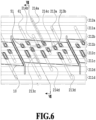
- a common flow path groove 62 and a common flow path groove 71 formed in each flow path member By joining the second flow path member 60 and the third flow path member 70, eight common flow paths which extend in a longitudinal direction of the flow path members are formed by a common flow path groove 62 and a common flow path groove 71 formed in each flow path member. Accordingly, for each color of the liquid, a set of the common supply flow path 211 and the common collection flow path 212 are formed inside the flow path member 210 (refer to FIG. 6 ). A communication port 72 of the third flow path member 70 is communicated with each hole of the joint rubber 100 and fluidically communicated with the liquid supply unit 220.
- the first to third flow path members are preferably made of a material with corrosion resistance against liquids and with a low coefficient of linear expansion.
- a base material of the flow path members for example, alumina, LCP (liquid crystal polymer), PPS (polyphenyl sulfide), PSF (polysulfone), or modified PPE (polyphenylene ether) can be suitably used.
- a composite material (resin material) created by adding an inorganic filler such as silica fine particles or fibers to the base material of the flow path members can be suitably used.
- the three flow path members may be laminated and glued to each other or, when a composite resin material is selected as the material, a joining method by welding may be used.
- a plurality of individual supply flow paths 213 (213a, 213b, 213c, and 213d) formed by the individual flow path groove 52 are connected via the communication port 61 to the common supply flow path 211 of each color.
- a plurality of individual collection flow paths 214 (214a, 214b, 214c, and 214d) formed by the individual flow path groove 52 are connected via the communication port 61 to the common collection flow path 212 of each color.
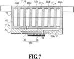
- FIG. 7 is a diagram showing a cross section taken along a line VII-VII in FIG. 6 .
- the individual supply flow path 213c and the individual collection flow path 214a are respectively communicated with the ejection module 200 via the communication port 51. Only the individual supply flow path 213c and the individual collection flow path 214a are illustrated in FIG. 7 .
- other individual supply flow paths (213a, 213b, and 213d) and other individual collection flow paths (214b, 214c, and 214d) are respectively communicated with the ejection module 200 as shown in FIG. 6 .
- a flow path for supplying ink from the first flow path member 50 to a printing element 15 (refer to FIG.
- a flow path for collecting (returning) a part of or all of the liquid supplied to the printing element 15 to the first flow path member 50 is formed in the support member 30 and the printing element substrate 10 included in each ejection module 200.
- the common supply flow path 211 of each color is connected via the liquid supply unit 220 to the negative pressure control unit 230 (high pressure side) of a corresponding color
- the common collection flow path 212 is connected via the liquid supply unit 220 to the negative pressure control unit 230 (low pressure side).
- the negative pressure control unit 230 is configured to create differential pressure (pressure difference) between the common supply flow path 211 and the common collection flow path 212. Therefore, in the liquid ejection head according to the present embodiment to which each flow path is connected as shown in FIG. 6 and FIG. 7 , a flow in the order of the common supply flow path 211, the individual supply flow path 213, the printing element substrate 10, the individual collection flow path 214, and the common collection flow path 212 is generated for each color.
- FIG. 8A shows a perspective view of a single ejection module 200
- FIG. 8B shows an exploded view of the ejection module 200.
- the printing element substrate 10 and the flexible wiring substrate 40 are bonded onto the support member 30 having been provided with a liquid communication port 31 in advance.
- a terminal 16 on the printing element substrate 10 and a terminal 41 on the flexible wiring substrate 40 are electrically connected by wire bonding and, subsequently, the wire-bonded section (electrically-connected section) is covered by a sealing material to form the sealed section 110.
- a terminal 42 on an opposite side to the printing element substrate 10 of the flexible wiring substrate 40 is electrically connected to a connecting terminal 93 (refer to FIG.
- the support member 30 is a support which supports the printing element substrate 10 and also a flow path member which fluidically communicates the printing element substrate 10 and the flow path member 210 with each other, preferably, the support member 30 has high flatness and can be joined to the printing element substrate with sufficiently high reliability.
- alumina or a resin material is preferable as a material of the support member 30.
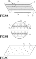
- FIG. 9A shows a plan view of a surface on the side where ejection orifices 13 are formed of the printing element substrate 10
- FIG. 9B shows an enlarged view of a portion indicated by IXb in FIG. 9A
- FIG. 9C shows a plan view of a rear surface of the printing element substrate 10 in FIG. 9A
- four ejection orifice arrays are formed on an ejection orifice forming member 12 of the printing element substrate 10.
- ejection orifice array direction a direction in which an ejection orifice array being an array of a plurality of ejection orifices 13 extends.
- the printing element 15 which is a heating element for generating bubbles from a liquid using thermal energy is arranged at a position corresponding to each ejection orifice 13.
- a pressure chamber 23 which internally includes the printing elements 15 are sectioned by partitions 22.
- the printing elements 15 are electrically connected to the terminal 16 shown in FIG. 9A by electric wiring (not illustrated) provided on the printing element substrate 10.
- the printing elements 15 generate heat based on a pulse signal inputted via the electric wiring substrate 90 ( FIG. 4 ) and the flexible wiring substrate 40 ( FIG. 8B ) from a control circuit of the printing apparatus 1000 and causes the liquid to boil.
- the liquid is ejected from the ejection orifices 13 by a bubbling force created by the boiling.
- a liquid supply path 18 extends on one side and a liquid collection path 19 extends on another side.
- the liquid supply path 18 and the liquid collection path 19 are flow paths provided on the printing element substrate 10 and extending in the ejection orifice array direction and are respectively communicated with the ejection orifices 13 via supply ports 17a and collection ports 17b.
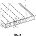
- FIG. 10 is a perspective view showing cross sections of the printing element substrate 10 and a lid member 20 taken along a plane X-X in FIG. 9A .
- a sheet-like lid member 20 is laminated on a rear surface of the surface on which the ejection orifices 13 are formed of the printing element substrate 10 and the lid member 20 is provided with a plurality of openings 21 which communicate with the liquid supply path 18 and the liquid collection path 19 to be described later.
- the lid member 20 is provided with three openings 21 with respect to one liquid supply path 18 and two openings 21 with respect to one liquid collection path 19.
- FIG. 10 is a perspective view showing cross sections of the printing element substrate 10 and a lid member 20 taken along a plane X-X in FIG. 9A .
- a sheet-like lid member 20 is laminated on a rear surface of the surface on which the ejection orifices 13 are formed of the printing element substrate 10 and the lid member 20 is provided with a plurality of openings 21 which communicate with the liquid supply path 18 and
- the substrate 11 formed of silicon and the ejection orifice forming member 12 formed of a photosensitive resin are laminated to construct the printing element substrate 10 and the lid member 20 is joined to the rear surface of the substrate 11.
- the printing element 15 (refer to FIG. 9B ) is formed on a side of one surface of the substrate 11 and a groove which constitutes the liquid supply path 18 and the liquid collection path 19 extending along the ejection orifice arrays is formed on a side of a rear surface of the substrate 11.
- the liquid supply path 18 and the liquid collection path 19 formed by the substrate 11 and the lid member 20 are respectively connected to the common supply flow path 211 and the common collection flow path 212 in the flow path member 210 and differential pressure is created between the liquid supply path 18 and the liquid collection path 19.
- differential pressure is created at an ejection orifice not performing an ejection operation. Due to the differential pressure, a liquid inside the liquid supply path 18 provided in the substrate 11 flows to the liquid collection path 19 via the supply port 17a, the pressure chamber 23, and the collection port 17b (a flow indicated by an arrow C in FIG. 10 ).
- the liquid collected to the liquid collection path 19 passes through the openings 21 and the liquid communication port 31 (refer to FIG. 8B ), collected in an order of the communication port 51 inside the flow path member 210, the individual collection flow path 214, and the common collection flow path 212, and finally collected to the supply flow path of the printing apparatus 1000.
- a liquid supplied from the printing apparatus main body to the liquid ejection head 3 is circulated, supplied, and collected in the following order.
- the liquid first flows into the liquid ejection head 3 from the liquid connecting part 111 of the liquid supply unit 220 and, after flowing through the negative pressure control unit 230, the liquid is supplied to the joint rubber 100.
- the liquid is then supplied in the order of the communication port 72 and the common flow path groove 71 provided in the third flow path member, the common flow path groove 62 and the communication port 61 provided in the second flow path member, and the individual flow path groove 52 and the communication port 51 provided in the first flow path member.
- the liquid is supplied to the pressure chamber 32 sequentially via the liquid communication port 31 provided in the support member 30, the openings 21 provided in the lid member 20, and the liquid supply path 18 and the supply port 17a provided in the substrate 11.
- the liquid supplied to the pressure chamber 23 the liquid not ejected from the ejection orifices 13 flows in an order of the collection port 17b and the liquid collection path 19 provided in the substrate 11, the openings 21 provided in the lid member 20, and the liquid communication port 31 provided in the support member 30.
- the liquid flows in the order of the communication port 51 and the individual flow path groove 52 provided in the first flow path member, the communication port 61 and the common flow path groove 62 provided in the second flow path member, the common flow path groove 71 and the communication port 72 provided in the third flow path member 70, and the joint rubber 100.
- the liquid flows to the outside of the liquid ejection head 3 from the liquid connecting part 111 provided in the liquid supply unit 220.
- FIG. 11 is a plan view showing, partially enlarged, an adjacent portion of printing element substrates in two adjacent ejection modules.
- printing element substrates with an approximately parallelogram shape are used in the present embodiment.
- each of the ejection orifice arrays (14a to 14d) in which ejection orifices 13 are arrayed in each printing element substrate 10 is arranged so as to be inclined by a certain angle with respect to the conveying direction of the printed medium. Accordingly, the ejection orifice arrays in an adjacent portion of printing element substrates 10 are configured so that at least one ejection orifice overlaps in the conveying direction of the printed medium.
- two ejection orifices on a line D are in an overlapping relationship with each other. Even when a position of the printing element substrate 10 deviates from a predetermined position to a certain extent, such an arrangement enables black stripes or blank areas in a printed image to be made less conspicuous due to drive control of the overlapping ejection orifices.
- the plurality of printing element substrates 10 may be arranged on a straight line (in-line) instead of a staggered arrangement. Even when arranged on a straight line, a configuration such as that shown in FIG.
- a main face of the printing element substrates is a parallelogram in the present embodiment, the present disclosure is not limited thereto and a configuration of the present disclosure can be preferably applied even when using printing element substrates that are a rectangle, a trapezoid, or another shape, for example.
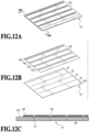
- FIG. 12A is a perspective view of a simplified ejection module in the first embodiment.
- FIG. 12B is an exploded perspective view of FIG. 12A.
- FIG. 12C is a sectional view taken along a line XIIc-XIIc in FIG. 12A .
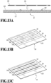
- FIG. 13A is a schematic view showing an adhesive-applied state in FIG. 12C .
- FIG. 13B and FIG. 13C are schematic views showing an example of an adhesive-applied position in FIG. 13A .
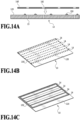
- FIG. 14A is a schematic view showing an example of the adhesive-applied state in FIG. 12C .
- FIG. 14B and FIG. 14C are schematic views showing an example of an adhesive-applied position in FIG. 14A .
- components have been partially simplified in order to facilitate understanding.
- the first embodiment differs from the basic configuration in that a protective member 140 is laminated on a front surface (ejection surface 120) of the ejection orifice forming member 12.
- the printing element substrate 10 includes the ejection surface 120.
- the ejection surface 120 is provided with a first ejection orifice array in which an ejection orifice configured to be capable of ejecting a liquid is arranged in plurality in an array direction and a second ejection orifice array arranged in a direction which intersects with the array direction and the first ejection orifice array.
- the protective member 140 is provided with a first opening which corresponds to the first ejection orifice array and a second opening which corresponds to the second ejection orifice array.
- the protective member 140 is arranged so as to be adjacent to the ejection surface 120 of the printing element substrate 10 via an adhesive arranged between the first ejection orifice array and the second ejection orifice array (hereinafter, also simply referred to as ejection orifice arrays 14).
- any ejection orifice array may be used as the first ejection orifice array.
- the ejection surface 120 is cleaned by a cleaning mechanism while abutting the cleaning mechanism.
- the cleaning mechanism is a wiper which abuts and cleans the ejection surface 120 or the protective member 140.
- the ejection surface 120 and the protective member 140 in the vicinity of the ejection orifice arrays 14 are preferably configured so that a gap is not created between the ejection surface 120 and the protective member 140. Therefore, the protective member 140 is desirably bonded to the ejection surface 120 so that floating of the protective member 140 hardly occurs. To this end, as shown in FIG. 13A to FIG.
- the adhesive 150 between adjacent ejection orifice arrays 14 is preferably applied to a part (for example, a central part) of an area between the adjacent ejection orifice arrays 14 in the array direction in which the ejection orifice arrays 14 are arrayed.
- the adhesive 150 may be continuously applied in the array direction of the ejection orifice arrays only between adjacent ejection orifice arrays 14 on the ejection surface 120. Accordingly, compared to intermittently applying the adhesive 150 on the ejection surface 120, an adhesion force between the ejection surface 120 and the protective member 140 can be made stronger. In addition, by applying the adhesive 150 only between adjacent ejection orifice arrays 14, an overflow of the adhesive 150 to an end in a longitudinal direction of the printing element substrate 10 can be suppressed. Adopting such a configuration can prevent an occurrence of a failure in which adhesive overflow prevents the printing element substrate 10 from being arranged when the printing element substrate 10 is arranged in plurality on a straight line (in-line) as shown in FIG. 11 .
- the adhesive 150 may be applied so as to enclose each of the plurality of ejection orifice arrays 14. Subsequently, as shown in FIG. 14A , the protective member 140 moves in a direction of an arrow and bonds with the ejection surface 120. Since adopting such a configuration increases locations where the adhesive 150 is applied, an adhesion force between the ejection surface 120 and the protective member 140 can be made even stronger. Furthermore, a method of forming an adhesion layer (not illustrated) on at least the side of the ejection surface 120 of the protective member 140 may also be suitably used in order to make the adhesion force between the ejection surface 120 and the protective member 140 even stronger. As the adhesive 150, for example, a thermosetting type of adhesive can be suitably used.
- a material of the protective member 140 preferably has a higher modulus of elasticity than a material of the ejection orifice forming member 12.
- a metal material such as stainless steel or aluminum, silicon, or alumina may be suitably used.
- the material of the protective member 140 is preferably a material having a coefficient of linear expansion that is close to a coefficient of linear expansion of the material of the printing element substrate 10.
- an outer shape of the protective member 140 and openings 141 are preferably processed with high accuracy.
- a processing method of the protective member 140 for example, etching, laser processing, or machining may be suitably used.
- the processing method when a burr or a raised edge is formed in the outer shape of the protective member 140 and an edge part of the openings 141, the possibility of the cleaning mechanism (not illustrated) becoming damaged can be reduced by using a surface on which the burr or the raised edge has been formed as an adhesive surface side with the ejection surface 120.
- the processing method of the protective member 140 may be changed between rear and front surfaces or for each location of the protective member 140.
- the outer shape of the protective member 140 and the openings 141 are given tapered shapes due to etching, by changing etching conditions and adjusting taper angles between the front and rear surfaces of the protective member 140, the liquid inside the liquid ejection head 3 can also be made more suitably collectible.
- Such a processing method can be relatively readily performed in a configuration in which the opening 141 is formed for each ejection orifice array 14 as in the present disclosure as compared to a configuration in which an opening is formed for each ejection orifice.
- the cleaning mechanism (not illustrated) of the printing apparatus abuts the protective member 140 laminated on the printing element substrate 10 to collect the liquid inside the liquid ejection head 3 and clean a periphery of the ejection orifices 13.
- a wiper made of a rubber material may be used as the cleaning mechanism (not illustrated).
- a ratio of a total area (an opening ratio) of the openings 141 of the protective member 140 to an area of a main face of the protective member 140 is preferably 70% or lower.
- a width of the respective openings 141 may be equal to or larger than a diameter of the respective ejection orifices and less than an interval between adjacent ejection orifice arrays and a thickness of the protective member 140 may be equal to or less than a thickness of the printing element substrate 10.
- the width of the respective openings 141 is set to 200 ⁇ m or more and the thickness of the protective member 140 is set to less than 50 ⁇ m. Accordingly, stress when the printed medium 2 and the printing element substrate 10 come into contact with each other can be reduced and the possibility of damaging the liquid ejection head 3 can be reduced while ensuring cleanability of the periphery of the ejection orifices 13. Furthermore, even when foreign objects such as dust has entered the pressure chamber 23 due to the printed medium 2 coming into contact with the ejection orifices 13, the foreign objects can be made to flow out from the pressure chamber 23 by circulating the liquid inside the pressure chamber 23 between the inside and the outside of the pressure chamber 23 as described earlier.
- FIG. 15A is a perspective view of a simplified ejection module representing a modification of FIG. 12A .
- FIG. 15B is an enlarged view of a portion denoted by XVb in FIG. 15A.
- FIG. 15C is an enlarged view of a portion denoted by XVc in FIG. 15A .
- components have been partially simplified in order to facilitate understanding.
- a corner part 143 of the protective member 140 may be formed in an R shape. Accordingly, a risk of damage to the cleaning mechanism (not illustrated) of the printing apparatus due to a corner part of the protective member 140 when the cleaning mechanism (not illustrated) abuts the liquid ejection head 3 during maintenance between print jobs can be reduced.
- Alignment marks 122a and 122b to be used for positioning between adjacent printing element substrates 10 may be formed on the printing element substrates 10.
- a printing element substrate number (not illustrated) for identification of the printing element substrate 10 or an ejection orifice number (not illustrated) for position identification of each ejection orifice 13 may be formed on the printing element substrate 10.
- openings 142a and 142b or notches (not illustrated) may be formed in the protective member 140 in conformity with the alignment marks 122a and 122b, the printing element substrate number (not illustrated), and the ejection orifice number (not illustrated).
- the notches (not illustrated) may be formed in an R shape. Accordingly, each printing element substrate 10 is capable of positioning each printing element substrate, identifying each printing element substrate, and identifying each ejection orifice.
- FIG. 16A is a perspective view of a simplified ejection module in the second embodiment.
- FIG. 16B is an exploded perspective view of FIG. 16A.
- FIG. 16C is a sectional view taken along a line XVIc-XVIc in FIG. 16A .
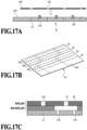
- FIG. 17A is a schematic view showing an adhesive-applied state in FIG. 16C .
- FIG. 17B is a schematic view showing an example of an adhesive-applied position in FIG. 17A.
- FIG. 17C is a schematic view showing details of a vicinity of a recessed part in FIG. 17A .
- components have been partially simplified in order to facilitate understanding.
- the second embodiment differs from the first embodiment in that recessed parts 121 are formed on the ejection surface 120. Specifically, as shown in FIG. 16A to FIG. 16C and FIG. 17A to FIG. 17C , recessed parts 121 are formed between adjacent ejection orifice arrays 14 on the ejection surface 120. In addition, the adhesive 150 is applied to the recessed parts 121 on the ejection surface 120 and the protective member 140 is moved in a direction of an arrow (an arrow direction in FIG. 17A ) and is bonded to the ejection surface 120.
- the recessed parts 121 may be formed at center between adjacent ejection orifice arrays 14.
- the recessed parts 121 are formed at center between adjacent ejection orifice arrays 14, the recessed parts 121 are not limited thereto and may be formed anywhere between the adjacent ejection orifice arrays 14 as long as an overflow of the adhesive does not occur when bonding the ejection surface 120 and the protective member 140 to each other. Adopting such a configuration enables an applied position of the adhesive 150 to be readily controlled. In addition, bonding between the ejection surface 120 and the protective member 140 enables an adhesion force to be made stronger as compared to simply applying the adhesive to a planer section of the ejection surface 120.
- an appropriate amount of the adhesive 150 spreads and an overflow of the adhesive 150 to an end in a longitudinal direction of the printing element substrate 10 can be suppressed. Accordingly, even when the printing element substrate 10 is arranged in plurality on a straight line (in-line) as shown in FIG. 11 , the printing element substrates can be arranged without causing an overflow of the adhesive.
- a depth of the recessed parts 121 may be a depth that prevents an overflow of the adhesive 150 when bonding the protective member 140 and the ejection surface 120 to each other and, for example, a preferable depth is 6 ⁇ m.
- the shape of the recessed parts may be formed in a semicircular shape, a triangular shape, or the like. Accordingly, an appropriate amount of the adhesive spreads between the ejection surface 120 and the protective member 140 and an overflow of the adhesive can be suppressed.
- the ejection surface 120 has repellency with respect to liquid but the recessed parts 121 have non-repellency. Accordingly, the adhesive 150 more readily pools in the recessed parts 121 ( FIG. 17A ) and a risk of the adhesive 150 flowing into the ejection orifices 13 can be reduced.
- An example of imparting non-repellency to the recessed parts 121 is a method of respectively forming the ejection orifices 13 with a repellent layer and the pressure chamber 23 with a non-repellent layer and forming the recessed parts 121 by removing parts of the repellent layer as shown in FIG. 17C .
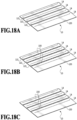
- FIG. 18A is a perspective view of a simplified printing element substrate representing a modification of FIG. 16B .
- FIG. 18B and FIG. 18C are schematic views showing an example of an adhesive-applied position in FIG. 18A .
- components have been partially simplified in order to facilitate understanding.
- the recessed parts 121 formed between adjacent ejection orifice arrays 14 may be formed by being connected in a groove shape.
- a width of the recessed parts 121 is preferably smaller than a beam width in adjacent openings 141. Accordingly, an overflow of the adhesive 150 to the side of the ejection orifices 13 when bonding the ejection surface 120 and the protective member 140 to each other can be prevented and a risk of the adhesive 150 flowing into the ejection orifices 13 can be reduced.
- FIG. 18A to FIG. 18C the recessed parts 121 formed between adjacent ejection orifice arrays 14 may be formed by being connected in a groove shape.
- a width of the recessed parts 121 is preferably smaller than a beam width in adjacent openings 141. Accordingly, an overflow of the adhesive 150 to the side of the ejection orifices 13 when bonding the ejection surface 120 and the protective member 140 to each other can be prevented and a risk of the adhesive 150 flowing into the ejection orifices 13 can
- the adhesive 150 may be continuously applied in the extending direction of the ejection orifice arrays in the recessed parts 121 formed in a groove shape. Accordingly, bonding between the ejection surface 120 and the protective member 140 can be made stronger as compared to intermittently applying the adhesive 150.
- a third embodiment of the present disclosure will be described. Descriptions of functions and components similar to the basic configuration, the first embodiment, and the second embodiment of the present disclosure will be omitted and different points will be described.
- FIG. 19A is a perspective view of a simplified ejection module in the third embodiment.
- FIG. 19B is an exploded perspective view of FIG. 19A.
- FIG. 19C is a sectional view taken along a line XIXc-XIXc in FIG. 19A .
- FIG. 20A is a schematic view showing an adhesive-applied state in FIG. 19C .
- FIG. 20B is a schematic view showing an example of an adhesive-applied position in FIG. 20A .
- components have been partially simplified in order to facilitate understanding.
- the third embodiment differs from the second embodiment in that recessed parts 121 are formed so as to enclose each of the plurality of ejection orifice arrays 14. Specifically, as shown in FIGS. 19A to 19C , FIG. 20A, and FIG. 20B , recessed parts 121 are formed so as to enclose each of the plurality of ejection orifice arrays 14 on the ejection surface 120.
- the adhesive 150 is applied to the recessed parts 121 on the ejection surface 120 and the protective member 140 is moved in a direction of an arrow (an arrow direction in FIG. 20A ) and is bonded to the ejection surface 120. Since adopting such a configuration increases locations where the ejection surface 120 and the protective member 140 are bonded to each other, bonding between the ejection surface 120 and the protective member 140 can be made even stronger.
- FIG. 21A is a perspective view of a simplified printing element substrate representing a modification of FIG. 19B .
- FIG. 21B and FIG. 21C are schematic views showing an example of an adhesive-applied position in FIG. 21A .
- components have been partially simplified in order to facilitate understanding.
- the recessed parts 121 formed so as to enclose each of the plurality of ejection orifice arrays 14 may be formed by being connected in a groove shape.
- FIG. 21B by intermittently applying the adhesive 150 in an extending direction of the ejection orifice arrays in the recessed parts 121 formed in a groove shape, usage of the adhesive 150 can be reduced.
- a risk of an overflow of the adhesive 150 to the side of the ejection orifices 13 during application or thermosetting of the adhesive and the adhesive 150 flowing into the ejection orifices 13 can be reduced.
- FIG. 21B by intermittently applying the adhesive 150 in an extending direction of the ejection orifice arrays in the recessed parts 121 formed in a groove shape, usage of the adhesive 150 can be reduced.
- a risk of an overflow of the adhesive 150 to the side of the ejection orifices 13 during application or thermosetting of the adhesive and the adhesive 150 flowing into the ejection orifices 13 can be reduced.
- FIG. 21B
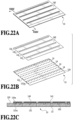
- FIG. 22A is a perspective view of a simplified ejection module in the fourth embodiment.
- FIG. 22B is an exploded perspective view of FIG. 22A.
- FIG. 22C is a sectional view taken along a line XXIIc-XXIIc in FIG. 22A .
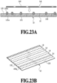
- FIG. 23A is a schematic view showing an adhesive-applied state in FIG. 22C .
- FIG. 23B is a schematic view showing an example of an adhesive-applied position in FIG. 23A .
- components have been partially simplified in order to facilitate understanding.
- the fourth embodiment differs from the third embodiment in that recessed parts 121a are formed on an outer side of an outermost ejection orifice array in a direction intersecting with an extending direction of the ejection orifice arrays 14.
- recessed parts 121 are formed so as to enclose each of the plurality of ejection orifice arrays 14 on the ejection surface 120.
- the recessed parts 121a are further formed on an outer side of the recessed parts 121 being formed so as to enclose each of the plurality of ejection orifice arrays 14 on the ejection surface 120.
- the adhesive 150 and an adhesive 150a are respectively applied to the recessed parts 121 and the recessed parts 121a on the ejection surface 120 and the protective member 140 is moved in a direction of an arrow (an arrow direction in FIG. 23A ) and is bonded to the ejection surface 120.
- a same adhesive is desirably used as the adhesive 150 and the adhesive 150a.
- the recessed parts 121a preferably have non-repellency with respect to the liquid in a similar manner to the recessed parts 121. Since adopting such a configuration increases bonding locations, bonding between the ejection surface 120 and the protective member 140 can be made even stronger.
- FIG. 24A is a perspective view of a simplified printing element substrate representing a modification of FIG. 22B .
- FIG. 24B and FIG. 24C are schematic views showing an example of an adhesive-applied position in FIG. 24A .
- components have been partially simplified in order to facilitate understanding.
- the recessed parts 121 formed so as to enclose each of the plurality of ejection orifice arrays 14 and the recessed parts 121a formed on an outer side of an outermost ejection orifice array in a direction intersecting with the extending direction of the ejection orifice arrays 14 may be respectively formed by being connected in a groove shape.
- FIG. 24B by respectively intermittently applying the adhesive 150 and the adhesive 150a to the recessed parts 121 and the recessed parts 121a formed in a groove shape, usage of the adhesive 150 and the adhesive 150a can be reduced.
- the adhesive 150 and the adhesive 150a are respectively applied in a continuous way in the extending direction of the ejection orifice arrays in the recessed parts 121 and the recessed parts 121a formed in a groove shape. Accordingly, compared to respectively intermittently applying the adhesive 150 and the adhesive 150a, bonding between the ejection surface 120 and the protective member 140 can be made stronger.
- FIG. 25 is a schematic view of a part of a simplified printing element substrate representing a modification of FIG. 24A to FIG. 24C .
- a sixth embodiment may be shaped such that when comparing a groove width in a transverse direction of the recessed parts 121 with a groove width in a transverse direction of the recessed parts 121a formed on the outer side of the outermost ejection orifice array in a direction intersecting with the extending direction of the ejection orifice arrays 14, the groove width in the transverse direction of the recessed parts 121a is narrower.
- a shape may be adopted in which a groove width in a transverse direction of a part of the recessed part 121 in the intersecting part of the recessed part 121 and the recessed part 121a is a same width as the width in the transverse direction of the recessed part 121a.
Landscapes
- Engineering & Computer Science (AREA)
- Manufacturing & Machinery (AREA)
- Physics & Mathematics (AREA)
- Optics & Photonics (AREA)
- Geometry (AREA)
- Particle Formation And Scattering Control In Inkjet Printers (AREA)
Abstract
A liquid ejection head (3) according to the present disclosure includes: a printing element substrate (10) including an ejection surface (120) provided with a first ejection orifice array (14a-14d) in which an ejection orifice configured to be capable of ejecting a liquid is arranged in plurality in an array direction and a second ejection orifice array (14a-14d) arranged in a direction intersecting with the array direction and the first ejection orifice array (14a-14d); and a protective member (140) provided with a first opening corresponding to the first ejection orifice array (14a-14d) and a second opening corresponding to the second ejection orifice array (14a-14d), wherein the protective member (140) is arranged adjacent to the ejection surface (120) of the printing element substrate (10) via an adhesive arranged between the first ejection orifice array (14a-14d) and the second ejection orifice array (14a-14d).
Description
- The present disclosure relates to a liquid ejection head.
- Line liquid ejection apparatuses are known which perform high-speed printing using a liquid ejection head corresponding to a width of a printed medium on which a plurality of printing element substrates are arranged. During continuous single-pass printing while continuously or intermittently conveying a plurality of printed media, a printed medium being conveyed may float upward and come into contact with a printing element substrate and damage the liquid ejection head.
Japanese Patent Laid-Open No. 2006-334910 Japanese Patent Laid-Open No. H4-234665 - However, with the configuration disclosed in Literature 1, there is a risk that the protective member may flake off from the ejection surface depending on an amount or an application method of an adhesive. In addition, with the configuration disclosed in
Literature 2, there is a concern that the protective member may flake off due to a shape of the protective member or stress created by a difference in coefficients of linear expansion between materials of the protective member and the ejection surface. - The present invention provides a liquid ejection head as specified in claims 1-29.
- Further features of the present invention will become apparent from the following description of exemplary embodiments with reference to the attached drawings.
-
-
FIG. 1 is a schematic configuration diagram of an inkjet printing apparatus according to the present disclosure; -
FIG. 2 is a schematic view of a liquid circulation path of the inkjet printing apparatus according to the present disclosure; -
FIG. 3A and FIG. 3B are a perspective view of a liquid ejection head according to the present disclosure; -
FIG. 4 is an exploded perspective view of the liquid ejection head according to the present disclosure; -
FIG. 5A to FIG. 5F are a diagram showing a front surface and a rear surface of each flow path member of the liquid ejection head according to the present disclosure; -
FIG. 6 is a partial enlarged perspective view of a flow path inside a flow path member of the liquid ejection head according to the present disclosure as viewed from a side of an ejection module; -
FIG. 7 is a sectional view taken along a line VII-VII inFIG. 6 ; -
FIG. 8A and FIG. 8B are a perspective view and an exploded view of a single ejection module of the liquid ejection head according to the present disclosure; -
FIG. 9A to FIG. 9C are a plan view and an enlarged view of a side of an ejection orifice surface of a printing element substrate of the liquid ejection head according to the present disclosure; -
FIG. 10 is a sectional perspective view of a surface X-X inFIG. 9A ; -
FIG. 11 is a partial enlarged view of adjacent printing element substrates of the liquid ejection head according to the present disclosure; -
FIG. 12A to FIG. 12C are a perspective view, an exploded perspective view, and a sectional view of an ejection module of a liquid ejection head according to a first embodiment; -
FIG. 13A to FIG. 13C are a schematic view showing an adhesive-applied state inFIG. 12C ; -
FIG. 14A to FIG. 14C are a schematic view showing an example of an adhesive-applied state in an ejection module of the liquid ejection head according to the first embodiment; -
FIG. 15A to FIG. 15C are a perspective view and a partial enlarged view showing a modification of an ejection module of the liquid ejection head according to the first embodiment; -
FIG. 16A to FIG. 16C are a perspective view, an exploded perspective view, and a sectional view of an ejection module of a liquid ejection head according to a second embodiment; -
FIG. 17A to FIG. 17C are a schematic view showing an adhesive-applied state inFIG. 16C ; -
FIG. 18A to FIG. 18C are a schematic perspective view showing a modification of a printing element substrate of the liquid ejection head according to the second embodiment; -
FIG. 19A to FIG.19C are a perspective view, an exploded perspective view, and a sectional view of an ejection module of a liquid ejection head according to a third embodiment; -
FIG. 20A and FIG. 20B are a schematic view showing an adhesive-applied state inFIG. 19C ; -
FIG. 21A to FIG.21C are a schematic perspective view showing a modification of a printing element substrate of the liquid ejection head according to the third embodiment; -
FIG. 22A to FIG. 22C are a perspective view, an exploded perspective view, and a sectional view of an ejection module of a liquid ejection head according to a fourth embodiment; -
FIG. 23A and FIG. 23B are a schematic view showing an adhesive-applied state inFIG. 22C ; -
FIG. 24A to FIG. 24C are a schematic perspective view showing a printing element substrate of a liquid ejection head according to a fifth embodiment; -
FIG. 25 is a schematic partial enlarged view showing a printing element substrate of a liquid ejection head according to a sixth embodiment; and -
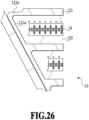
FIG. 26 is a schematic partial enlarged view showing a printing element substrate of a liquid ejection head according to a seventh embodiment. - Hereinafter, examples of embodiments of the present disclosure will be described with reference to the drawings. However, it is to be understood that the following description is not intended to limit the scope of the present disclosure. As an example, while a thermal system which generates bubbles using a heating element to eject a liquid is adopted in the present embodiments, the present disclosure can also be applied to liquid ejection heads adopting a piezoelectric system and other various liquid ejection systems.
- While the present embodiments represent an inkjet printing apparatus (printing apparatus) formed so as to circulate a liquid such as ink between a tank and a liquid ejection head, the inkjet printing apparatus may be given other forms. For example, instead of circulating ink, the inkjet printing apparatus may be provided with two tanks, respectively, on an upstream side and a downstream side of a liquid ejection head and may be formed to cause ink inside a pressure chamber to flow by supplying the ink from one tank to the other tank.
- In addition, while the present embodiments represent a so-called line head having a length corresponding to a width of a printed medium, the present disclosure can also be applied to a so-called serial liquid ejection head which performs printing while scanning a printed medium. An example of a serial liquid ejection head is a configuration which is respectively mounted with one printing element substrate for black ink and one printing element substrate for color ink. The liquid ejection head according to the present disclosure is not limited thereto and may be formed so as to create a short line head which is shorter than a width of a printed medium and in which several printing element substrates are arranged so that ejection orifices overlap with each other in an ejection orifice array direction and to scan the printed medium with the short line head.
-
FIG. 1 shows a schematic configuration of an apparatus which ejects a liquid or, more particularly, an inkjet printing apparatus 1000 (hereinafter, also referred to as a printing apparatus) which performs printing by ejecting ink according to the present disclosure. Theprinting apparatus 1000 is a line printing apparatus which includes a conveying section 1 which conveys a printedmedium 2 and a lineliquid ejection head 3 which is arranged approximately orthogonal to a conveying direction of the printed medium and which performs continuous single-pass printing while continuously or intermittently conveying a plurality of printedmedia 2. The printedmedium 2 is not limited to cut paper and may be continuous rolled paper. Theliquid ejection head 3 is capable of full-color (cyan, magenta, yellow, and black) printing using CMYK ink. In addition, as will be described later, liquid supplying means which is a supply path for supplying a liquid to the liquid ejection head, a main tank, and a buffer tank (refer toFIG. 2 ) are fluidically connected to theliquid ejection head 3. Furthermore, an electric control section which transmits power and ejection control signals to theliquid ejection head 3 is electrically connected to theliquid ejection head 3. A liquid path and an electric signal path in theliquid ejection head 3 will be described later. -
FIG. 2 is a schematic view showing a circulation path applied to the printing apparatus according to the present disclosure in which theliquid ejection head 3 is fluidically connected to a first circulatingpump 1002, abuffer tank 1003, and the like. Note thatFIG. 2 only shows a path by which an ink of one color among CMYK ink flows for the sake of brevity. Thebuffer tank 1003 as a sub-tank to be connected to amain tank 1006 includes an air communication port (not illustrated) which communicates the inside of the tank to the outside and is capable of discharging bubbles inside the ink to the outside. Thebuffer tank 1003 is also connected to areplenishing pump 1005. When liquid is consumed in theliquid ejection head 3 due to the ejection (discharge) of ink from an ejection orifice of the liquid ejection head for the purpose of printing, suction recovery, or the like by ejecting ink, thereplenishing pump 1005 transfers ink corresponding to a consumed amount from themain tank 1006 to thebuffer tank 1003. - The first circulating
pump 1002 has a role of extracting a liquid from aliquid connecting part 111 of theliquid ejection head 3 and feeding the liquid to thebuffer tank 1003. A displacement pump with a quantitative liquid feeding capability is preferably used as the first circulatingpump 1002. While specific examples include a tube pump, a gear pump, a diaphragm pump, a syringe pump, and the like, for example, even a form of arranging a general constant-flow valve or a relief valve at a pump outlet to secure a constant flow rate can be adopted. When theliquid ejection head 3 is being driven, the first circulatingpump 1002 causes a certain amount of ink to flow inside a commoncollection flow path 212. A flow rate of the ink is preferably set to or above a level at which a temperature difference between respectiveprinting element substrates 10 inside theliquid ejection head 3 does not affect printing image quality. Obviously, setting an excessively large flow rate results in excessive negative pressure between the respectiveprinting element substrates 10 due to an effect of a pressure drop of a flow path inside aliquid ejection unit 300 and unevenness in density is created in an image. Therefore, the flow rate is preferably set while taking a temperature difference and a negative pressure difference between the respectiveprinting element substrates 10 into consideration. - A negative
pressure control unit 230 is provided between paths connecting a second circulatingpump 1004 and theliquid ejection unit 300 to each other. Therefore, the negativepressure control unit 230 has a function of operating so as to maintain pressure on a downstream side of the negative pressure control unit 230 (in other words, the side of the liquid ejection unit 300) at constant pressure set in advance even when a flow rate of a circulation system fluctuates due to a difference in duties of performing printing. As two pressure adjustment mechanisms that constitute the negativepressure control unit 230, any mechanism may be used as long as the mechanism is capable of controlling pressure on a downstream side of the mechanism itself to a fluctuation within or below a certain range centered on desired set pressure. As an example, a mechanism similar to a so-called "pressure-reducing regulator" can be used. When using a pressure-reducing regulator, as shown inFIG. 2 , pressure is preferably applied by the second circulatingpump 1004 to an upstream side of the negativepressure control unit 230 via aliquid supply unit 220. Accordingly, since an effect of water head pressure with respect to theliquid ejection head 3 of thebuffer tank 1003 can be suppressed, a degree of freedom of layout of thebuffer tank 1003 in theprinting apparatus 1000 can be expanded. The second circulatingpump 1004 need only have pump head pressure of certain pressure or higher within a range of an ink circulation flow rate used when driving theliquid ejection head 3 and a turbo pump, a displacement pump, or the like can be used. Specifically, a diaphragm pump or the like can be applied. In addition, for example, a water head tank arranged with a certain water head difference with respect to the negativepressure control unit 230 can also be applied instead of the second circulatingpump 1004. - As shown in
FIG. 2 , the negativepressure control unit 230 includes two pressure adjustment mechanisms respectively set to mutually different control pressure. Among the two negative pressure adjustment mechanisms, a side set to relatively high pressure (denoted by H inFIG. 2 ) and a side set to relatively low pressure (denoted by L inFIG. 2 ) are respectively connected to a commonsupply flow path 211 and a commoncollection flow path 212 in theliquid ejection unit 300 via theliquid supply unit 220. Theliquid ejection unit 300 is provided with the commonsupply flow path 211, the commoncollection flow path 212, and an individualsupply flow path 213 and an individualcollection flow path 214 which communicate with each printing element substrate. The individualsupply flow path 213 and the individualcollection flow path 214 are respectively communicated with the commonsupply flow path 211 and the commoncollection flow path 212. Accordingly, a part of the liquid fed by the first circulatingpump 1002 passes through an internal flow path of theprinting element substrate 10 from the commonsupply flow path 211 and flows into the common collection flow path 212 (arrow inFIG. 2 ). This is because a pressure difference is provided between the pressure adjustment mechanism H connected to the commonsupply flow path 211 and the pressure adjustment mechanism L connected to the commoncollection flow path 212 and the first circulatingpump 1002 is only connected to the commoncollection flow path 212. - In this manner, in the
liquid ejection unit 300, a flow of a liquid which passes inside the commoncollection flow path 212 and a flow from the commonsupply flow path 211 which passes through an internal flow path inside eachprinting element substrate 10 and reaches the commoncollection flow path 212 are created. Therefore, heat generated in eachprinting element substrate 10 can be discharged to the outside of theprinting element substrate 10 by the flow from the commonsupply flow path 211 to the commoncollection flow path 212 while suppressing an increase in pressure loss. In addition, since the configuration described above enables, when performing printing by theliquid ejection head 3, a flow of ink to be created in an ejection orifice not involved in the printing or in a pressure chamber, thickening of ink in such parts can be suppressed. Furthermore, thickened ink and foreign objects in the ink can be discharged to the commoncollection flow path 212. As a result, theliquid ejection head 3 according to the present example enables high-speed and high-quality printing to be performed. - A configuration of the
liquid ejection head 3 according to the present embodiment will be described.FIG. 3A and FIG. 3B are perspective views of theliquid ejection head 3 according to the present embodiment. Theliquid ejection head 3 is a line liquid ejection head in which 15printing element substrates 10, each of which being capable of single-handedly ejecting ink in a plurality of colors, are arrayed in a single line (arranged in-line). As shown inFIG. 3A , theliquid ejection head 3 includessignal input terminals 91 andpower supply terminals 92 electrically connected to eachprinting element substrate 10 viaflexible wiring substrates 40 and anelectric wiring substrate 90. Thesignal input terminals 91 and thepower supply terminals 92 are electrically connected to a control section of theprinting apparatus 1000 and respectively supply theprinting element substrates 10 with an ejection drive signal and power necessary for ejection. By consolidating wiring with an electric circuit inside theelectric wiring substrate 90, the numbers of thesignal input terminals 91 and thepower supply terminal 92 can be reduced as compared to the number ofprinting element substrates 10. Accordingly, the number of electrically connected parts which need to be disconnected when assembling theliquid ejection head 3 with respect to theprinting apparatus 1000 or when replacing the liquid ejection head can be reduced. As shown inFIG. 3B ,liquid connecting parts 111 provided on one side of theliquid ejection head 3 are connected to a liquid supply system of theprinting apparatus 1000. Accordingly, ink is supplied from the supply system of theprinting apparatus 1000 to theliquid ejection head 3 and ink having passed through theliquid ejection head 3 is collected by the supply system of theprinting apparatus 1000. In this manner, ink of each color can be circulated via a path of theprinting apparatus 1000 and a path of theliquid ejection head 3. - Next, a configuration of the
liquid ejection head 3 will be specifically described with reference toFIG. 4. FIG. 4 shows an exploded perspective view of each component or unit which constitutes theliquid ejection head 3. Theliquid ejection unit 300, theliquid supply unit 220, and theelectric wiring substrate 90 are mounted to acase 80. Theliquid supply unit 220 is provided with the liquid connecting parts 111 (refer toFIG. 3A and FIG. 3B ) and internally provided with a separate filter 221 (refer toFIG. 2 ) for each color which communicates with each opening of theliquid connecting parts 111 in order to remove foreign objects in supplied ink. Theliquid supply unit 220 is provided withfilters 221 for four colors. A liquid having passed through thefilters 221 is supplied to the negativepressure control unit 230 arranged on theliquid supply unit 220 so as to correspond to each color. The negativepressure control unit 230 is a unit made up of a separate pressure-regulating valve for each color. Due to actions of valves, spring members, and the like respectively provided inside the negativepressure control unit 230, the negativepressure control unit 230 significantly attenuates a change in pressure drop inside a supply system of the printing apparatus 1000 (an upstream-side supply system of the liquid ejection head 3) which occurs with a fluctuation in a flow rate of the liquid. Accordingly, the negativepressure control unit 230 can stabilize a change in negative pressure on a downstream side of the pressure control unit (on a side of the liquid ejection unit 300) within a certain range. As shown inFIG. 2 , two pressure-regulating valves for each color are built into the negativepressure control unit 230 of each color and the pressure-regulating valves are respectively set to different control pressure. In addition, a high pressure side of the negativepressure control unit 230 is communicated with the commonsupply flow path 211 inside theliquid ejection unit 300 and a low pressure side of the negativepressure control unit 230 is communicated with the commoncollection flow path 212 inside theliquid ejection unit 300, respectively via theliquid supply unit 220. - The
case 80 which is constituted of a liquid ejectionunit support portion 81 and an electric wiringsubstrate support portion 82 supports theliquid ejection unit 300 and theelectric wiring substrate 90 and secures stiffness of theliquid ejection head 3. The electric wiringsubstrate support portion 82 is for supporting theelectric wiring substrate 90 and is fixed to the liquid ejectionunit support portion 81 by screwing. The liquid ejectionunit support portion 81 has a role of correcting warpage or deformation of theliquid ejection unit 300 and securing accuracy of relative positions of the plurality ofprinting element substrates 10 and, accordingly, suppresses streaks or unevenness in a printed subject. Therefore, the liquid ejectionunit support portion 81 preferably has sufficient stiffness and suitable materials include a metal material such as SUS or aluminum or a ceramic such as alumina. The liquid ejectionunit support portion 81 is provided withopenings joint rubber 100 is to be inserted. A liquid supplied from theliquid supply unit 220 is guided via the joint rubber to aflow path member 210 which constitutes theliquid ejection unit 300. - The
liquid ejection unit 300 is made up of a plurality of theejection modules 200 and theflow path member 210 and acover member 130 is mounted to a printed medium-side surface of theliquid ejection unit 300. In this case, as shown inFIG. 4 , thecover member 130 is a member having a frame-like surface provided with anelongated opening 131 and theprinting element substrate 10 and a sealed section 110 (FIG. 8A and FIG. 8B ) included in theejection module 200 are exposed from theopening 131. A frame section in a periphery of theopening 131 has a feature as an abutting surface of a cap member which caps theliquid ejection head 3 during print stand-by. Therefore, a closed space is preferably formed when theliquid ejection head 3 is capped by applying an adhesive, a sealing material, a filler, or the like along the periphery of theopening 131 to fill concavities and convexities or gaps on an ejection orifice surface of theliquid ejection unit 300. - Next, a configuration of the
flow path member 210 included in theliquid ejection unit 300 will be described. As shown inFIG. 4 , theflow path member 210 is a laminate of a firstflow path member 50, a secondflow path member 60, and a thirdflow path member 70. In addition, theflow path member 210 is a flow path member for distributing the liquid supplied from theliquid supply unit 220 to eachejection module 200 and for returning the liquid that flows back from theejection module 200 to theliquid supply unit 220. Theflow path member 210 is fixed to the liquid ejectionunit support portion 81 by screwing and, accordingly, warpage and deformation of theflow path member 210 are suppressed. -
FIG. 5A to FIG. 5F are diagrams showing a front surface and a rear surface of each of the first to third flow path members.FIG. 5A shows a surface on a side on which theejection module 200 is mounted of the firstflow path member 50 andFIG. 5F shows a surface which abuts the liquid ejectionunit support portion 81 of the thirdflow path member 70. The firstflow path member 50 and the secondflow path member 60 are joined so thatFIG. 5B and FIG. 5C representing abutting surfaces of the respective flow path members oppose each other, and the secondflow path member 60 and the thirdflow path member 70 are joined so thatFIG. 5D and FIG. 5E representing abutting surfaces of the respective flow path members oppose each other. By joining the secondflow path member 60 and the thirdflow path member 70, eight common flow paths which extend in a longitudinal direction of the flow path members are formed by a common flow path groove 62 and a common flow path groove 71 formed in each flow path member. Accordingly, for each color of the liquid, a set of the commonsupply flow path 211 and the commoncollection flow path 212 are formed inside the flow path member 210 (refer toFIG. 6 ). Acommunication port 72 of the thirdflow path member 70 is communicated with each hole of thejoint rubber 100 and fluidically communicated with theliquid supply unit 220.Communication ports 61 are formed in plurality on a bottom surface of the common flow path groove 62 of the secondflow path member 60 and are communicated with one end section of an individual flow path groove 52 of the firstflow path member 50. Acommunication port 51 is formed in another end section of the individual flow path groove 52 of the firstflow path member 50 and is fluidically communicated with the plurality ofejection modules 200 via thecommunication port 51. The individual flow path groove 52 enables flow paths to be consolidated on a center side of the flow path members. - The first to third flow path members are preferably made of a material with corrosion resistance against liquids and with a low coefficient of linear expansion. As a base material of the flow path members, for example, alumina, LCP (liquid crystal polymer), PPS (polyphenyl sulfide), PSF (polysulfone), or modified PPE (polyphenylene ether) can be suitably used. In addition, as a material of the flow path members, a composite material (resin material) created by adding an inorganic filler such as silica fine particles or fibers to the base material of the flow path members can be suitably used. As a formation method of the
flow path member 210, the three flow path members may be laminated and glued to each other or, when a composite resin material is selected as the material, a joining method by welding may be used. - Next, a connection relationship of the respective flow paths in the
flow path member 210 will be described usingFIG. 6. FIG. 6 is a perspective view of an enlargement of a part of flow paths inside theflow path member 210 which is formed by joining the first to third flow path members as viewed from the surface on which theejection module 200 is mounted of the firstflow path member 50. Common supply flow paths 211 (211a, 211b, 211c, and 211d) and common collection flow paths 212 (212a, 212b, 212c, and 212d) which extend in a longitudinal direction of theliquid ejection head 3 for each color are provided in theflow path member 210. A plurality of individual supply flow paths 213 (213a, 213b, 213c, and 213d) formed by the individual flow path groove 52 are connected via thecommunication port 61 to the commonsupply flow path 211 of each color. In addition, a plurality of individual collection flow paths 214 (214a, 214b, 214c, and 214d) formed by the individual flow path groove 52 are connected via thecommunication port 61 to the commoncollection flow path 212 of each color. Such a flow path configuration enables ink to be consolidated to theprinting element substrate 10 positioned in a center section of the flow path members from each commonsupply flow path 211 via the individualsupply flow paths 213. Furthermore, ink can be collected to each commoncollection flow path 212 from theprinting element substrates 10 via the individualcollection flow paths 214. -
FIG. 7 is a diagram showing a cross section taken along a line VII-VII inFIG. 6 . As shown in the diagram, the individualsupply flow path 213c and the individualcollection flow path 214a are respectively communicated with theejection module 200 via thecommunication port 51. Only the individualsupply flow path 213c and the individualcollection flow path 214a are illustrated inFIG. 7 . On the other hand, on other cross sections, other individual supply flow paths (213a, 213b, and 213d) and other individual collection flow paths (214b, 214c, and 214d) are respectively communicated with theejection module 200 as shown inFIG. 6 . A flow path for supplying ink from the firstflow path member 50 to a printing element 15 (refer toFIG. 9 ) provided in theprinting element substrate 10 is formed in asupport member 30 and theprinting element substrate 10 included in eachejection module 200. In addition, a flow path for collecting (returning) a part of or all of the liquid supplied to theprinting element 15 to the firstflow path member 50 is formed in thesupport member 30 and theprinting element substrate 10 included in eachejection module 200. In this case, the commonsupply flow path 211 of each color is connected via theliquid supply unit 220 to the negative pressure control unit 230 (high pressure side) of a corresponding color, and the commoncollection flow path 212 is connected via theliquid supply unit 220 to the negative pressure control unit 230 (low pressure side). The negativepressure control unit 230 is configured to create differential pressure (pressure difference) between the commonsupply flow path 211 and the commoncollection flow path 212. Therefore, in the liquid ejection head according to the present embodiment to which each flow path is connected as shown inFIG. 6 andFIG. 7 , a flow in the order of the commonsupply flow path 211, the individualsupply flow path 213, theprinting element substrate 10, the individualcollection flow path 214, and the commoncollection flow path 212 is generated for each color. -
FIG. 8A shows a perspective view of asingle ejection module 200 andFIG. 8B shows an exploded view of theejection module 200. As a method of manufacturing theejection module 200, first, theprinting element substrate 10 and theflexible wiring substrate 40 are bonded onto thesupport member 30 having been provided with a liquid communication port 31 in advance. Subsequently, a terminal 16 on theprinting element substrate 10 and a terminal 41 on theflexible wiring substrate 40 are electrically connected by wire bonding and, subsequently, the wire-bonded section (electrically-connected section) is covered by a sealing material to form the sealedsection 110. A terminal 42 on an opposite side to theprinting element substrate 10 of theflexible wiring substrate 40 is electrically connected to a connecting terminal 93 (refer toFIG. 4 ) of theelectric wiring substrate 90. Since thesupport member 30 is a support which supports theprinting element substrate 10 and also a flow path member which fluidically communicates theprinting element substrate 10 and theflow path member 210 with each other, preferably, thesupport member 30 has high flatness and can be joined to the printing element substrate with sufficiently high reliability. For example, alumina or a resin material is preferable as a material of thesupport member 30. - A configuration of the
printing element substrate 10 according to the present embodiment will be described.FIG. 9A shows a plan view of a surface on the side where ejection orifices 13 are formed of theprinting element substrate 10,FIG. 9B shows an enlarged view of a portion indicated by IXb inFIG. 9A, and FIG. 9C shows a plan view of a rear surface of theprinting element substrate 10 inFIG. 9A . As shown inFIG. 9A , four ejection orifice arrays, each of which corresponds to each ink color, are formed on an ejectionorifice forming member 12 of theprinting element substrate 10. Hereinafter, a direction in which an ejection orifice array being an array of a plurality ofejection orifices 13 extends will be referred to as an "ejection orifice array direction". - As shown in
FIG. 9B , theprinting element 15 which is a heating element for generating bubbles from a liquid using thermal energy is arranged at a position corresponding to eachejection orifice 13. Apressure chamber 23 which internally includes theprinting elements 15 are sectioned bypartitions 22. Theprinting elements 15 are electrically connected to the terminal 16 shown inFIG. 9A by electric wiring (not illustrated) provided on theprinting element substrate 10. In addition, theprinting elements 15 generate heat based on a pulse signal inputted via the electric wiring substrate 90 (FIG. 4 ) and the flexible wiring substrate 40 (FIG. 8B ) from a control circuit of theprinting apparatus 1000 and causes the liquid to boil. The liquid is ejected from the ejection orifices 13 by a bubbling force created by the boiling. As shown inFIG. 9B , along each ejection orifice array, aliquid supply path 18 extends on one side and aliquid collection path 19 extends on another side. Theliquid supply path 18 and theliquid collection path 19 are flow paths provided on theprinting element substrate 10 and extending in the ejection orifice array direction and are respectively communicated with the ejection orifices 13 viasupply ports 17a andcollection ports 17b. -
FIG. 10 is a perspective view showing cross sections of theprinting element substrate 10 and alid member 20 taken along a plane X-X inFIG. 9A . As shown inFIG. 9C andFIG. 10 , a sheet-like lid member 20 is laminated on a rear surface of the surface on which the ejection orifices 13 are formed of theprinting element substrate 10 and thelid member 20 is provided with a plurality ofopenings 21 which communicate with theliquid supply path 18 and theliquid collection path 19 to be described later. For example, in the present embodiment, thelid member 20 is provided with threeopenings 21 with respect to oneliquid supply path 18 and twoopenings 21 with respect to oneliquid collection path 19. As shown inFIG. 9B , each opening 21 of thelid member 20 is communicated with the plurality ofcommunication ports 51 shown inFIG. 5A . As shown inFIG. 10 , thelid member 20 has a function as a lid which forms a part of a wall of theliquid supply path 18 and theliquid collection path 19 formed on asubstrate 11 of theprinting element substrate 10. Thelid member 20 preferably has sufficient corrosion resistance with respect to liquids and, in addition, from the perspective of preventing mixing of color, high accuracy is required of an opening shape and an opening position of theopenings 21. Therefore, preferably, a photosensitive resin material or a silicon plate is used as a material of thelid member 20 and theopenings 21 are provided by a photolithography process. In this manner, thelid member 20 changes a pitch of flow paths using theopenings 21 and, when pressure loss is taken into consideration, thelid member 20 is desirably thin and constituted of a film-like member. - Next, a flow of a liquid inside the
printing element substrate 10 will be described. Thesubstrate 11 formed of silicon and the ejectionorifice forming member 12 formed of a photosensitive resin are laminated to construct theprinting element substrate 10 and thelid member 20 is joined to the rear surface of thesubstrate 11. The printing element 15 (refer toFIG. 9B ) is formed on a side of one surface of thesubstrate 11 and a groove which constitutes theliquid supply path 18 and theliquid collection path 19 extending along the ejection orifice arrays is formed on a side of a rear surface of thesubstrate 11. Theliquid supply path 18 and theliquid collection path 19 formed by thesubstrate 11 and thelid member 20 are respectively connected to the commonsupply flow path 211 and the commoncollection flow path 212 in theflow path member 210 and differential pressure is created between theliquid supply path 18 and theliquid collection path 19. When a liquid is being ejected from the plurality ofejection orifices 13 of theliquid ejection head 3 and printing is being performed, differential pressure is created at an ejection orifice not performing an ejection operation. Due to the differential pressure, a liquid inside theliquid supply path 18 provided in thesubstrate 11 flows to theliquid collection path 19 via thesupply port 17a, thepressure chamber 23, and thecollection port 17b (a flow indicated by an arrow C inFIG. 10 ). Due to the flow, thickened ink created by evaporation from the ejection orifices 13, bubbles, foreign objects, and the like in theejection orifice 13 not engaged in printing or in thepressure chamber 23 can be collected to theliquid collection path 19. In addition, thickening of ink in the ejection orifices 13 and thepressure chamber 23 can be suppressed. The liquid collected to theliquid collection path 19 passes through theopenings 21 and the liquid communication port 31 (refer toFIG. 8B ), collected in an order of thecommunication port 51 inside theflow path member 210, the individualcollection flow path 214, and the commoncollection flow path 212, and finally collected to the supply flow path of theprinting apparatus 1000. - In other words, a liquid supplied from the printing apparatus main body to the
liquid ejection head 3 is circulated, supplied, and collected in the following order. In the circulation path shown inFIG. 2 , the liquid first flows into theliquid ejection head 3 from theliquid connecting part 111 of theliquid supply unit 220 and, after flowing through the negativepressure control unit 230, the liquid is supplied to thejoint rubber 100. The liquid is then supplied in the order of thecommunication port 72 and the common flow path groove 71 provided in the third flow path member, the common flow path groove 62 and thecommunication port 61 provided in the second flow path member, and the individual flow path groove 52 and thecommunication port 51 provided in the first flow path member. Subsequently, the liquid is supplied to the pressure chamber 32 sequentially via the liquid communication port 31 provided in thesupport member 30, theopenings 21 provided in thelid member 20, and theliquid supply path 18 and thesupply port 17a provided in thesubstrate 11. Among the liquid supplied to thepressure chamber 23, the liquid not ejected from the ejection orifices 13 flows in an order of thecollection port 17b and theliquid collection path 19 provided in thesubstrate 11, theopenings 21 provided in thelid member 20, and the liquid communication port 31 provided in thesupport member 30. Subsequently, the liquid flows in the order of thecommunication port 51 and the individual flow path groove 52 provided in the first flow path member, thecommunication port 61 and the common flow path groove 62 provided in the second flow path member, the common flow path groove 71 and thecommunication port 72 provided in the thirdflow path member 70, and thejoint rubber 100. In addition, the liquid flows to the outside of theliquid ejection head 3 from theliquid connecting part 111 provided in theliquid supply unit 220. In this manner, in the liquid ejection head of the present embodiment, since thickening of a liquid in the pressure chamber or in a vicinity of ejection orifices ca be suppressed, a position error of ejection and ink non-discharge can be suppressed and, consequently, printing with high image quality can be performed. - While a material of the ejection orifice forming member in the present embodiment is a photosensitive resin, the present disclosure is not limited thereto and a configuration of the present disclosure can be preferably applied even when using silicon, a metal, a ceramic, glass, or other materials, for example.
-
FIG. 11 is a plan view showing, partially enlarged, an adjacent portion of printing element substrates in two adjacent ejection modules. As shown inFIG. 9A , printing element substrates with an approximately parallelogram shape are used in the present embodiment. As shown inFIG. 11 , each of the ejection orifice arrays (14a to 14d) in which ejection orifices 13 are arrayed in eachprinting element substrate 10 is arranged so as to be inclined by a certain angle with respect to the conveying direction of the printed medium. Accordingly, the ejection orifice arrays in an adjacent portion ofprinting element substrates 10 are configured so that at least one ejection orifice overlaps in the conveying direction of the printed medium. InFIG. 11 , two ejection orifices on a line D are in an overlapping relationship with each other. Even when a position of theprinting element substrate 10 deviates from a predetermined position to a certain extent, such an arrangement enables black stripes or blank areas in a printed image to be made less conspicuous due to drive control of the overlapping ejection orifices. The plurality ofprinting element substrates 10 may be arranged on a straight line (in-line) instead of a staggered arrangement. Even when arranged on a straight line, a configuration such as that shown inFIG. 11 enables measures against black stripes or blank areas in an overlap portion ofprinting element substrates 10 to be taken while preventing a length of theliquid ejection head 3 in a conveying direction (a direction of an arrow inFIG. 11 ) of a printed medium from increasing. While a main face of the printing element substrates is a parallelogram in the present embodiment, the present disclosure is not limited thereto and a configuration of the present disclosure can be preferably applied even when using printing element substrates that are a rectangle, a trapezoid, or another shape, for example. - A first embodiment of the present disclosure will be described. Descriptions of functions and components similar to the basic configuration of the present disclosure will be omitted and different points will be described.
-
FIG. 12A is a perspective view of a simplified ejection module in the first embodiment.FIG. 12B is an exploded perspective view ofFIG. 12A. FIG. 12C is a sectional view taken along a line XIIc-XIIc inFIG. 12A .FIG. 13A is a schematic view showing an adhesive-applied state inFIG. 12C .FIG. 13B and FIG. 13C are schematic views showing an example of an adhesive-applied position inFIG. 13A .FIG. 14A is a schematic view showing an example of the adhesive-applied state inFIG. 12C .FIG. 14B and FIG. 14C are schematic views showing an example of an adhesive-applied position inFIG. 14A . InFIG. 12A to FIG. 12C ,FIG. 13A to FIG. 13C , andFIG. 14A to FIG. 14C , components have been partially simplified in order to facilitate understanding. - The first embodiment differs from the basic configuration in that a
protective member 140 is laminated on a front surface (ejection surface 120) of the ejectionorifice forming member 12. Specifically, as shown inFIG. 12A to FIG. 12C , theprinting element substrate 10 includes theejection surface 120. Theejection surface 120 is provided with a first ejection orifice array in which an ejection orifice configured to be capable of ejecting a liquid is arranged in plurality in an array direction and a second ejection orifice array arranged in a direction which intersects with the array direction and the first ejection orifice array. Theprotective member 140 is provided with a first opening which corresponds to the first ejection orifice array and a second opening which corresponds to the second ejection orifice array. In addition, theprotective member 140 is arranged so as to be adjacent to theejection surface 120 of theprinting element substrate 10 via an adhesive arranged between the first ejection orifice array and the second ejection orifice array (hereinafter, also simply referred to as ejection orifice arrays 14). Note that among theejection orifice arrays 14a to 14d, any ejection orifice array may be used as the first ejection orifice array. As will be described later, theejection surface 120 is cleaned by a cleaning mechanism while abutting the cleaning mechanism. For example, the cleaning mechanism is a wiper which abuts and cleans theejection surface 120 or theprotective member 140. In order to have the cleaning mechanism (not illustrated) collect the liquid inside theliquid ejection head 3 in a more suitable manner, theejection surface 120 and theprotective member 140 in the vicinity of theejection orifice arrays 14 are preferably configured so that a gap is not created between theejection surface 120 and theprotective member 140. Therefore, theprotective member 140 is desirably bonded to theejection surface 120 so that floating of theprotective member 140 hardly occurs. To this end, as shown inFIG. 13A to FIG. 13C , for example, an adhesive 150
is applied to theejection surface 120 between adjacentejection orifice arrays 14 and theejection surface 120 is bonded to theprotective member 140 by the adhesive 150. As shown inFIG. 13A , theprotective member 140 is moved in a direction of an arrow so that theprotective member 140 bonds with theejection surface 120. As shown inFIG. 13B , by intermittently applying the adhesive 150 in the array direction of the ejection orifice arrays between adjacentejection orifice arrays 14, usage of the adhesive 150 can be reduced. In addition, a risk of an overflow of the adhesive 150 to the side of the ejection orifices 13 during application or thermosetting of the adhesive and the adhesive 150 flowing into the ejection orifices 13 can be reduced. When applying the adhesive 150 between adjacentejection orifice arrays 14, as shown inFIG. 13B , the adhesive is preferably applied to a part (for example, a central part) of an area between the adjacentejection orifice arrays 14 in the array direction in which theejection orifice arrays 14 are arrayed. - On the other hand, as shown in
FIG. 13C , the adhesive 150 may be continuously applied in the array direction of the ejection orifice arrays only between adjacentejection orifice arrays 14 on theejection surface 120. Accordingly, compared to intermittently applying the adhesive 150 on theejection surface 120, an adhesion force between theejection surface 120 and theprotective member 140 can be made stronger. In addition, by applying the adhesive 150 only between adjacentejection orifice arrays 14, an overflow of the adhesive 150 to an end in a longitudinal direction of theprinting element substrate 10 can be suppressed. Adopting such a configuration can prevent an occurrence of a failure in which adhesive overflow prevents theprinting element substrate 10 from being arranged when theprinting element substrate 10 is arranged in plurality on a straight line (in-line) as shown inFIG. 11 . - On the other hand, as shown in
FIG. 14A to FIG. 14C , the adhesive 150 may be applied so as to enclose each of the plurality ofejection orifice arrays 14. Subsequently, as shown inFIG. 14A , theprotective member 140 moves in a direction of an arrow and bonds with theejection surface 120. Since adopting such a configuration increases locations where the adhesive 150 is applied, an adhesion force between theejection surface 120 and theprotective member 140 can be made even stronger. Furthermore, a method of forming an adhesion layer (not illustrated) on at least the side of theejection surface 120 of theprotective member 140 may also be suitably used in order to make the adhesion force between theejection surface 120 and theprotective member 140 even stronger. As the adhesive 150, for example, a thermosetting type of adhesive can be suitably used. - Such a configuration enables the
protective member 140 to prevent the printed medium 2 (refer toFIG. 1 ) and theprinting element substrate 10 from coming into contact with each other when the printedmedium 2 floats during conveyance and a possibility of theliquid ejection head 3 becoming damaged can be reduced. Therefore, a material of theprotective member 140 preferably has a higher modulus of elasticity than a material of the ejectionorifice forming member 12. As the material of theprotective member 140, for example, a metal material such as stainless steel or aluminum, silicon, or alumina may be suitably used. Above all, the material of theprotective member 140 is preferably a material having a coefficient of linear expansion that is close to a coefficient of linear expansion of the material of theprinting element substrate 10. Accordingly, a risk of theprotective member 140 flaking off from the ejectionorifice forming member 12 can be reduced. In addition, an outer shape of theprotective member 140 andopenings 141 are preferably processed with high accuracy. As a processing method of theprotective member 140, for example, etching, laser processing, or machining may be suitably used. By the processing method, when a burr or a raised edge is formed in the outer shape of theprotective member 140 and an edge part of theopenings 141, the possibility of the cleaning mechanism (not illustrated) becoming damaged can be reduced by using a surface on which the burr or the raised edge has been formed as an adhesive surface side with theejection surface 120. In addition, the processing method of theprotective member 140 may be changed between rear and front surfaces or for each location of theprotective member 140. For example, since the outer shape of theprotective member 140 and theopenings 141 are given tapered shapes due to etching, by changing etching conditions and adjusting taper angles between the front and rear surfaces of theprotective member 140, the liquid inside theliquid ejection head 3 can also be made more suitably collectible. Such a processing method can be relatively readily performed in a configuration in which theopening 141 is formed for eachejection orifice array 14 as in the present disclosure as compared to a configuration in which an opening is formed for each ejection orifice. - During maintenance between one print job in which printing is performed on a printed medium and a next print job, the cleaning mechanism (not illustrated) of the printing apparatus abuts the
protective member 140 laminated on theprinting element substrate 10 to collect the liquid inside theliquid ejection head 3 and clean a periphery of the ejection orifices 13. For example, a wiper made of a rubber material may be used as the cleaning mechanism (not illustrated). By having the wiper abut both theprotective member 140 and theejection surface 120, even when the liquid is sticking to a periphery of the ejection orifices 13, the liquid inside theliquid ejection head 3 can be collected and the periphery of the ejection orifices 13 can be cleaned more suitably. - When the
openings 141 of theprotective member 140 are excessively large, the possibility of the printedmedium 2 and theprinting element substrate 10 coming into contact with each other and damaging theliquid ejection head 3 increases when the printedmedium 2 floats during conveyance due to a paper jam or the like. Therefore, a ratio of a total area (an opening ratio) of theopenings 141 of theprotective member 140 to an area of a main face of theprotective member 140 is preferably 70% or lower. In addition, a width of therespective openings 141 may be equal to or larger than a diameter of the respective ejection orifices and less than an interval between adjacent ejection orifice arrays and a thickness of theprotective member 140 may be equal to or less than a thickness of theprinting element substrate 10. For example, preferably, the width of therespective openings 141 is set to 200 µm or more and the thickness of theprotective member 140 is set to less than 50 µm. Accordingly, stress when the printedmedium 2 and theprinting element substrate 10 come into contact with each other can be reduced and the possibility of damaging theliquid ejection head 3 can be reduced while ensuring cleanability of the periphery of the ejection orifices 13. Furthermore, even when foreign objects such as dust has entered thepressure chamber 23 due to the printedmedium 2 coming into contact with the ejection orifices 13, the foreign objects can be made to flow out from thepressure chamber 23 by circulating the liquid inside thepressure chamber 23 between the inside and the outside of thepressure chamber 23 as described earlier. -
FIG. 15A is a perspective view of a simplified ejection module representing a modification ofFIG. 12A .FIG. 15B is an enlarged view of a portion denoted by XVb inFIG. 15A. FIG. 15C is an enlarged view of a portion denoted by XVc inFIG. 15A . InFIG. 15A to FIG. 15C , components have been partially simplified in order to facilitate understanding. - As a modification of the first embodiment, as shown in
FIG. 15B and FIG. 15C , acorner part 143 of theprotective member 140 may be formed in an R shape. Accordingly, a risk of damage to the cleaning mechanism (not illustrated) of the printing apparatus due to a corner part of theprotective member 140 when the cleaning mechanism (not illustrated) abuts theliquid ejection head 3 during maintenance between print jobs can be reduced. - Alignment marks 122a and 122b to be used for positioning between adjacent
printing element substrates 10 may be formed on theprinting element substrates 10. In addition, a printing element substrate number (not illustrated) for identification of theprinting element substrate 10 or an ejection orifice number (not illustrated) for position identification of eachejection orifice 13 may be formed on theprinting element substrate 10. In order to identify these components,openings protective member 140 in conformity with the alignment marks 122a and 122b, the printing element substrate number (not illustrated), and the ejection orifice number (not illustrated). The notches (not illustrated) may be formed in an R shape. Accordingly, eachprinting element substrate 10 is capable of positioning each printing element substrate, identifying each printing element substrate, and identifying each ejection orifice. - A second embodiment of the present disclosure will be described. Descriptions of functions and components similar to the basic configuration and the first embodiment of the present disclosure will be omitted and different points will be described.
-
FIG. 16A is a perspective view of a simplified ejection module in the second embodiment.FIG. 16B is an exploded perspective view ofFIG. 16A. FIG. 16C is a sectional view taken along a line XVIc-XVIc inFIG. 16A .FIG. 17A is a schematic view showing an adhesive-applied state inFIG. 16C .FIG. 17B is a schematic view showing an example of an adhesive-applied position inFIG. 17A. FIG. 17C is a schematic view showing details of a vicinity of a recessed part inFIG. 17A . InFIG. 16A to FIG. 16C andFIG. 17A to FIG. 17C , components have been partially simplified in order to facilitate understanding. - The second embodiment differs from the first embodiment in that recessed
parts 121 are formed on theejection surface 120. Specifically, as shown inFIG. 16A to FIG. 16C andFIG. 17A to FIG. 17C , recessedparts 121 are formed between adjacentejection orifice arrays 14 on theejection surface 120. In addition, the adhesive 150 is applied to the recessedparts 121 on theejection surface 120 and theprotective member 140 is moved in a direction of an arrow (an arrow direction inFIG. 17A ) and is bonded to theejection surface 120. The recessedparts 121 may be formed at center between adjacentejection orifice arrays 14. While the recessedparts 121 are formed at center between adjacentejection orifice arrays 14, the recessedparts 121 are not limited thereto and may be formed anywhere between the adjacentejection orifice arrays 14 as long as an overflow of the adhesive does not occur when bonding theejection surface 120 and theprotective member 140 to each other. Adopting such a configuration enables an applied position of the adhesive 150 to be readily controlled. In addition, bonding between theejection surface 120 and theprotective member 140 enables an adhesion force to be made stronger as compared to simply applying the adhesive to a planer section of theejection surface 120. Furthermore, by applying the adhesive 150 only between adjacentejection orifice arrays 14, an appropriate amount of the adhesive 150 spreads and an overflow of the adhesive 150 to an end in a longitudinal direction of theprinting element substrate 10 can be suppressed. Accordingly, even when theprinting element substrate 10 is arranged in plurality on a straight line (in-line) as shown inFIG. 11 , the printing element substrates can be arranged without causing an overflow of the adhesive. - A depth of the recessed
parts 121 may be a depth that prevents an overflow of the adhesive 150 when bonding theprotective member 140 and theejection surface 120 to each other and, for example, a preferable depth is 6 µm. In addition, while the recessedparts 121 are formed on theejection surface 120 in the present embodiment, the shape of the recessed parts may be formed in a semicircular shape, a triangular shape, or the like. Accordingly, an appropriate amount of the adhesive spreads between theejection surface 120 and theprotective member 140 and an overflow of the adhesive can be suppressed. - Preferably, the
ejection surface 120 has repellency with respect to liquid but the recessedparts 121 have non-repellency. Accordingly, the adhesive 150 more readily pools in the recessed parts 121 (FIG. 17A ) and a risk of the adhesive 150 flowing into the ejection orifices 13 can be reduced. An example of imparting non-repellency to the recessedparts 121 is a method of respectively forming the ejection orifices 13 with a repellent layer and thepressure chamber 23 with a non-repellent layer and forming the recessedparts 121 by removing parts of the repellent layer as shown inFIG. 17C . -
FIG. 18A is a perspective view of a simplified printing element substrate representing a modification ofFIG. 16B .FIG. 18B and FIG. 18C are schematic views showing an example of an adhesive-applied position inFIG. 18A . InFIG. 18A to FIG. 18C , components have been partially simplified in order to facilitate understanding. - As a modification of the second embodiment, as shown in
FIG. 18A to FIG. 18C , the recessedparts 121 formed between adjacentejection orifice arrays 14 may be formed by being connected in a groove shape. A width of the recessedparts 121 is preferably smaller than a beam width inadjacent openings 141. Accordingly, an overflow of the adhesive 150 to the side of the ejection orifices 13 when bonding theejection surface 120 and theprotective member 140 to each other can be prevented and a risk of the adhesive 150 flowing into the ejection orifices 13 can be reduced. In addition, as an example, as shown inFIG. 18B , by intermittently applying the adhesive 150 in an extending direction of the ejection orifice arrays in the recessedparts 121 formed in a groove shape, usage of the adhesive 150 can be reduced. Furthermore, a risk of an overflow of the adhesive 150 to the side of the ejection orifices 13 during application or thermosetting of the adhesive and the adhesive 150 flowing into the ejection orifices 13 can be reduced. On the other hand, as shown inFIG. 18C , the adhesive 150 may be continuously applied in the extending direction of the ejection orifice arrays in the recessedparts 121 formed in a groove shape. Accordingly, bonding between theejection surface 120 and theprotective member 140 can be made stronger as compared to intermittently applying the adhesive 150. - A third embodiment of the present disclosure will be described. Descriptions of functions and components similar to the basic configuration, the first embodiment, and the second embodiment of the present disclosure will be omitted and different points will be described.
-
FIG. 19A is a perspective view of a simplified ejection module in the third embodiment.FIG. 19B is an exploded perspective view ofFIG. 19A. FIG. 19C is a sectional view taken along a line XIXc-XIXc inFIG. 19A .FIG. 20A is a schematic view showing an adhesive-applied state inFIG. 19C .FIG. 20B is a schematic view showing an example of an adhesive-applied position inFIG. 20A . InFIG. 19A to FIG. 19C ,FIG. 20A, and FIG. 20B , components have been partially simplified in order to facilitate understanding. - The third embodiment differs from the second embodiment in that recessed
parts 121 are formed so as to enclose each of the plurality ofejection orifice arrays 14. Specifically, as shown inFIGS. 19A to 19C ,FIG. 20A, and FIG. 20B , recessedparts 121 are formed so as to enclose each of the plurality ofejection orifice arrays 14 on theejection surface 120. In addition, the adhesive 150 is applied to the recessedparts 121 on theejection surface 120 and theprotective member 140 is moved in a direction of an arrow (an arrow direction inFIG. 20A ) and is bonded to theejection surface 120. Since adopting such a configuration increases locations where theejection surface 120 and theprotective member 140 are bonded to each other, bonding between theejection surface 120 and theprotective member 140 can be made even stronger. -
FIG. 21A is a perspective view of a simplified printing element substrate representing a modification ofFIG. 19B .FIG. 21B and FIG. 21C are schematic views showing an example of an adhesive-applied position inFIG. 21A . InFIG. 21A to FIG. 21C , components have been partially simplified in order to facilitate understanding. - As a modification of the third embodiment, as shown in
FIG. 21A to FIG. 21C , the recessedparts 121 formed so as to enclose each of the plurality ofejection orifice arrays 14 may be formed by being connected in a groove shape. As an example, as shown inFIG. 21B , by intermittently applying the adhesive 150 in an extending direction of the ejection orifice arrays in the recessedparts 121 formed in a groove shape, usage of the adhesive 150 can be reduced. In addition, a risk of an overflow of the adhesive 150 to the side of the ejection orifices 13 during application or thermosetting of the adhesive and the adhesive 150 flowing into the ejection orifices 13 can be reduced. On the other hand, as shown inFIG. 21C , by continuously applying the adhesive 150 in an extending direction of the ejection orifice arrays in the recessedparts 121 formed in a groove shape, bonding between theejection surface 120 and theprotective member 140 can be made even stronger as compared to intermittently applying the adhesive 150. - A fourth embodiment of the present disclosure will be described. Descriptions of functions and components similar to the basic configuration and the first to third embodiments of the present disclosure will be omitted and different points will be described.
-
FIG. 22A is a perspective view of a simplified ejection module in the fourth embodiment.FIG. 22B is an exploded perspective view ofFIG. 22A. FIG. 22C is a sectional view taken along a line XXIIc-XXIIc inFIG. 22A .FIG. 23A is a schematic view showing an adhesive-applied state inFIG. 22C .FIG. 23B is a schematic view showing an example of an adhesive-applied position inFIG. 23A . InFIG. 22A to FIG. 22C ,FIG. 23A, and FIG. 23B , components have been partially simplified in order to facilitate understanding. - The fourth embodiment differs from the third embodiment in that recessed
parts 121a are formed on an outer side of an outermost ejection orifice array in a direction intersecting with an extending direction of theejection orifice arrays 14. Specifically, as shown inFIG. 22A to FIG. 22C ,FIG. 23A, and FIG. 23B , recessedparts 121 are formed so as to enclose each of the plurality ofejection orifice arrays 14 on theejection surface 120. In addition, the recessedparts 121a are further formed on an outer side of the recessedparts 121 being formed so as to enclose each of the plurality ofejection orifice arrays 14 on theejection surface 120. Furthermore, the adhesive 150 and an adhesive 150a are respectively applied to the recessedparts 121 and the recessedparts 121a on theejection surface 120 and theprotective member 140 is moved in a direction of an arrow (an arrow direction inFIG. 23A ) and is bonded to theejection surface 120. A same adhesive is desirably used as the adhesive 150 and the adhesive 150a. In addition, the recessedparts 121a preferably have non-repellency with respect to the liquid in a similar manner to the recessedparts 121. Since adopting such a configuration increases bonding locations, bonding between theejection surface 120 and theprotective member 140 can be made even stronger. -
FIG. 24A is a perspective view of a simplified printing element substrate representing a modification ofFIG. 22B .FIG. 24B and FIG. 24C are schematic views showing an example of an adhesive-applied position inFIG. 24A . InFIG. 24A to FIG. 24C , components have been partially simplified in order to facilitate understanding. - As a fifth embodiment, as shown in
FIG. 24A to FIG. 24C , the recessedparts 121 formed so as to enclose each of the plurality ofejection orifice arrays 14 and the recessedparts 121a formed on an outer side of an outermost ejection orifice array in a direction intersecting with the extending direction of theejection orifice arrays 14 may be respectively formed by being connected in a groove shape. As an example, as shown inFIG. 24B , by respectively intermittently applying the adhesive 150 and the adhesive 150a to the recessedparts 121 and the recessedparts 121a formed in a groove shape, usage of the adhesive 150 and the adhesive 150a can be reduced. In addition, a risk of an overflow of the adhesive 150 to the side of the ejection orifices 13 during application or thermosetting of the adhesive and the adhesive 150 flowing into the ejection orifices 13 can be reduced. On the other hand, as shown inFIG. 24C , the adhesive 150 and the adhesive 150a are respectively applied in a continuous way in the extending direction of the ejection orifice arrays in the recessedparts 121 and the recessedparts 121a formed in a groove shape. Accordingly, compared to respectively intermittently applying the adhesive 150 and the adhesive 150a, bonding between theejection surface 120 and theprotective member 140 can be made stronger. -
FIG. 25 is a schematic view of a part of a simplified printing element substrate representing a modification ofFIG. 24A to FIG. 24C . - A sixth embodiment may be shaped such that when comparing a groove width in a transverse direction of the recessed
parts 121 with a groove width in a transverse direction of the recessedparts 121a formed on the outer side of the outermost ejection orifice array in a direction intersecting with the extending direction of theejection orifice arrays 14, the groove width in the transverse direction of the recessedparts 121a is narrower. - Since adopting such a shape causes an adhesive to penetrate into the recessed
parts 121a by capillary force by simply applying the adhesive to the recessedparts 121 and enables a step of applying the adhesive to the recessedparts 121a to be omitted, process time can be reduced. - In a relationship between the
protective member 140 and the groove widths of the recessedparts 121 and the recessedparts 121a, adhesion strength increases when the groove widths of the recessedparts 121 and the recessedparts 121a are wider. On the other hand, the groove widths of the recessedparts 121 and the recessedparts 121a are preferably narrower than theprotective member 140 so that overflow of the adhesive to theejection surface 120 from theprotective member 140 does not occur. In addition, with respect to a width in a transverse direction of theprotective member 140 between ejection orifice arrays, an area of an ejection orifice array opening portion affects a recovery action for refreshing the ejection orifices. Furthermore, in terms of recoverability, the larger the area of the ejection orifice array opening portion and, conversely, the narrower the width in the transverse direction of theprotective member 140 between ejection orifice arrays, the higher the recoverability. In a preferable example, the width in the transverse direction of theprotective member 140 between ejection orifice arrays ranges from 200 µm or more and 250 µm or less, the groove width in the transverse direction of the recessedparts 121 ranges from 80 µm or more and 120 µm or less, and the groove width in the transverse direction of the recessedparts 121a ranges from 30 µm or more and 70 µm or less. - In addition, a part of an intersecting part of the recessed
part 121 and the recessedpart 121a may have a chamfered shape as shown inFIG. 25 . Accordingly, an adhesive more readily flows from the recessedpart 121 to the recessedpart 121a. Furthermore, in a portion where the intersecting part has an obtuse angle, the ease with which the adhesive flows is not significantly increased by chamfering. Therefore, a portion where the intersecting part has an obtuse angle may be given a non-chamfered shape, and by increasing portions which are not chamfered, an area of openings between the ejection orifice arrays can be increased and an effect on recoverability can be reduced. - In addition, as shown in
FIG. 25 , a remaining part between a chip end in an ejection orifice array direction and the recessedpart 121a is formed. In order to maintain strength of the protective member while further reducing a distance between chips in the case of a head configuration in which the chips are arranged by being lined up in the ejection orifice array direction, a chipend remaining part 130 is preferably configured so that a groove width of the recessedpart 121a does not become too narrow. In a preferable example, a width in a transverse direction of the chipend remaining part 130 is 5 µm or more and 20 µm or less. -
FIG. 26 is a schematic view of a part of a simplified printing element substrate representing a modification ofFIG. 25 . - As a seventh embodiment, as shown in
FIG. 26 , a shape may be adopted in which a groove width in a transverse direction of a part of the recessedpart 121 in the intersecting part of the recessedpart 121 and the recessedpart 121a is a same width as the width in the transverse direction of the recessedpart 121a.
While the present invention has been described with reference to exemplary embodiments, it is to be understood that the invention is not limited to the disclosed exemplary embodiments. The scope of the following claims is to be accorded the broadest interpretation so as to encompass all such modifications and equivalent structures and functions.
Claims (29)
- A liquid ejection head (3), comprising:a printing element substrate (10) including an ejection surface (120) provided with a first ejection orifice array (14a-14d) in which an ejection orifice configured to be capable of ejecting a liquid is arranged in plurality in an array direction and a second ejection orifice array (14a-14d) arranged in a direction intersecting with the array direction and the first ejection orifice array (14a-14d); anda protective member (140) provided with a first opening corresponding to the first ejection orifice array (14a-14d) and a second opening corresponding to the second ejection orifice array (14a-14d), whereinthe protective member (140) is arranged adjacent to the ejection surface (120) of the printing element substrate (10) via an adhesive arranged between the first ejection orifice array (14a-14d) and the second ejection orifice array (14a-14d).
- The liquid ejection head according to claim 1, wherein the adhesive is intermittently applied in array directions of the first ejection orifice array and the second ejection orifice array.
- The liquid ejection head according to claim 1, wherein the adhesive is continuously applied in array directions of the first ejection orifice array and the second ejection orifice array.
- The liquid ejection head according to any of claims 1 to 3, wherein a recessed part is formed on the ejection surface and the adhesive is applied to the recessed part.
- The liquid ejection head according to claim 4, wherein the recessed part is formed so as to enclose each of the first ejection orifice array and the second ejection orifice array.
- The liquid ejection head according to claim 5, wherein a recessed part is further formed on the ejection surface on an outer side of the recessed part which is formed so as to enclose each of the first ejection orifice array and the second ejection orifice array.
- The liquid ejection head according to any one of claims 4-6, wherein the recessed parts are connected in a groove shape.
- The liquid ejection head according to claim 7, wherein a width of the recessed parts is smaller than a beam width between the openings of the protective member.
- The liquid ejection head according to any one of claims 4-8, wherein the ejection surface has repellency with respect to the liquid and the recessed parts have non-repellency with respect to the liquid.
- The liquid ejection head according to any one of claims 1-9, wherein the ejection surface is made of resin.
- The liquid ejection head according to any one of claims 1-10, wherein a ratio of a total area of the openings to an area of a main face of the protective member is 70% or lower.
- The liquid ejection head according to any one of claims 1-11, whereina width of the respective openings is equal to or larger than a diameter of the respective ejection orifices and less than an interval between the first ejection orifice array and the second ejection orifice array, anda thickness of the protective member is equal to or smaller than a thickness of the printing element substrate.
- The liquid ejection head according to any one of claims 1-12, wherein a width of the respective openings is 200 µm or more and a thickness of the protective member is less than 50 µm.
- The liquid ejection head according to any one of claims 1-13, wherein an opening or a notch is formed in the protective member in conformity with an alignment mark, a printing element substrate number, or an ejection orifice number provided on the printing element substrate.
- The liquid ejection head according to claim 14, wherein the notch is formed in an R shape.
- The liquid ejection head according to any one of claims 1-15, wherein corners of the protective member are formed in an R shape.
- The liquid ejection head according to any one of claims 1-16, wherein a material of the protective member has a higher modulus of elasticity than a material of the ejection orifices.
- The liquid ejection head according to any one of claims 1-17, wherein a material of the protective member has a same coefficient of linear expansion as a material of the printing element substrate.
- The liquid ejection head according to any one of claims 1-18, wherein the protective member is made of metal.
- The liquid ejection head according to claim 19, wherein the protective member is made of stainless steel.
- The liquid ejection head according to any one of claims 19 or 20, wherein an adhesion layer is formed on at least a side of the ejection surface of the protective member.
- The liquid ejection head according to any one of claims 1-21, wherein the printing element substrate is arrayed in plurality on a flow path member so that at least parts overlap with each other.
- The liquid ejection head according to any one of claims 1-22, wherein the liquid ejection head is a line head corresponding to a width of a printed medium.
- The liquid ejection head according to any one of claims 1-23, comprising:an energy generating element used to eject a liquid; anda pressure chamber internally including the energy generating element, whereina liquid in the pressure chamber is circulated between inside and outside of the pressure chamber.
- The liquid ejection head according to claim 5, wherein a groove in a first direction in which the recessed part is formed between the first ejection orifice array and the second ejection orifice array and a groove in a second direction which intersects with the groove in the first direction are formed, and the recessed part is shaped such that a width of the recessed part in which the groove in the second direction is formed is narrower than an average width of the recessed part which is formed in the groove in the first direction.
- The liquid ejection head according to claim 25, wherein an average width of the groove in the first direction is 80 µm or more and 150 µm or less and a width of the groove in the second direction is 20 µm or more and 70 µm or less.
- The liquid ejection head according to claim 25, wherein an intersecting part of the groove in the first direction and the groove in the second direction has a chamfered shape.
- The liquid ejection head according to claim 25, wherein only an acute angle part of an intersecting part of the groove in the first direction and the groove in the second direction has a chamfered shape.
- The liquid ejection head according to claim 25, wherein a width between the groove in the second direction and a chip end in an ejection orifice array direction is 5 µm or more and 20 µm or less.
Applications Claiming Priority (2)
| Application Number | Priority Date | Filing Date | Title |
|---|---|---|---|
| JP2022211846 | 2022-12-28 | ||
| JP2023175278A JP2024095522A (en) | 2022-12-28 | 2023-10-10 | Liquid ejection head |
Publications (1)
| Publication Number | Publication Date |
|---|---|
| EP4393712A1 true EP4393712A1 (en) | 2024-07-03 |
Family
ID=89222771
Family Applications (1)
| Application Number | Title | Priority Date | Filing Date |
|---|---|---|---|
| EP23216622.3A Pending EP4393712A1 (en) | 2022-12-28 | 2023-12-14 | Liquid ejection head |
Country Status (2)
| Country | Link |
|---|---|
| US (1) | US20240217233A1 (en) |
| EP (1) | EP4393712A1 (en) |
Citations (3)
| Publication number | Priority date | Publication date | Assignee | Title |
|---|---|---|---|---|
| JPH04234665A (en) | 1991-01-08 | 1992-08-24 | Seiko Epson Corp | Ink-jet recording head |
| JP2006334910A (en) | 2005-06-01 | 2006-12-14 | Brother Ind Ltd | Inkjet head |
| US20200047499A1 (en) * | 2018-08-10 | 2020-02-13 | Sii Printek Inc. | Liquid jet head and liquid jet recording device |
Family Cites Families (2)
| Publication number | Priority date | Publication date | Assignee | Title |
|---|---|---|---|---|
| JP2005125638A (en) * | 2003-10-24 | 2005-05-19 | Sony Corp | Liquid discharge head, liquid discharge apparatus, and method of manufacturing liquid discharge head |
| US7169538B2 (en) * | 2004-09-10 | 2007-01-30 | Lexmark International, Inc. | Process for making a micro-fluid ejection head structure |
-
2023
- 2023-12-14 EP EP23216622.3A patent/EP4393712A1/en active Pending
- 2023-12-27 US US18/397,115 patent/US20240217233A1/en active Pending
Patent Citations (3)
| Publication number | Priority date | Publication date | Assignee | Title |
|---|---|---|---|---|
| JPH04234665A (en) | 1991-01-08 | 1992-08-24 | Seiko Epson Corp | Ink-jet recording head |
| JP2006334910A (en) | 2005-06-01 | 2006-12-14 | Brother Ind Ltd | Inkjet head |
| US20200047499A1 (en) * | 2018-08-10 | 2020-02-13 | Sii Printek Inc. | Liquid jet head and liquid jet recording device |
Also Published As
| Publication number | Publication date |
|---|---|
| US20240217233A1 (en) | 2024-07-04 |
Similar Documents
| Publication | Publication Date | Title |
|---|---|---|
| KR102179743B1 (en) | Liquid ejection substrate, liquid ejection head, and liquid ejection apparatus | |
| JP7764414B2 (en) | Liquid discharge method | |
| JP7019328B2 (en) | Liquid discharge head | |
| EP3192657B1 (en) | Liquid ejection substrate, liquid ejection head, and liquid ejection apparatus | |
| JP7005143B2 (en) | Liquid discharge head and liquid discharge device | |
| JP2019014174A (en) | Liquid discharge head, liquid discharge apparatus, and liquid supply method | |
| KR20170083501A (en) | Liquid discharge head and liquid discharge method | |
| JP2019064254A (en) | Liquid supply apparatus, liquid discharge apparatus, liquid discharge module, and liquid supply method | |
| JP6714362B2 (en) | Liquid ejection head and liquid ejection device | |
| JP6900179B2 (en) | Liquid discharge head | |
| JP6740041B2 (en) | Liquid ejection method, liquid ejection apparatus, and liquid ejection head | |
| JP7182984B2 (en) | Liquid ejection head and liquid ejection device | |
| JP2017124608A (en) | Liquid ejection device and liquid ejection head | |
| JP6914645B2 (en) | Liquid discharge head and liquid discharge device | |
| JP2023001621A (en) | Liquid storage container and liquid discharge device | |
| EP4393712A1 (en) | Liquid ejection head | |
| JP6708414B2 (en) | Liquid ejection head, liquid ejection device, and method for manufacturing liquid ejection head | |
| US10603910B2 (en) | Liquid discharge head and liquid discharge method | |
| EP4393711A2 (en) | Liquid ejection head and liquid ejection apparatus comprising the same | |
| US12576637B2 (en) | Liquid ejection head and liquid ejection apparatus | |
| US20240351331A1 (en) | Liquid ejection head | |
| CN118254474A (en) | Liquid jet head | |
| JP6877970B2 (en) | Liquid discharge head and liquid discharge method | |
| KR102167589B1 (en) | Recording element board and liquid discharge head | |
| US12617205B2 (en) | Liquid ejection head and manufacturing method of liquid ejection head |
Legal Events
| Date | Code | Title | Description |
|---|---|---|---|
| PUAI | Public reference made under article 153(3) epc to a published international application that has entered the european phase |
Free format text: ORIGINAL CODE: 0009012 |
|
| STAA | Information on the status of an ep patent application or granted ep patent |
Free format text: STATUS: THE APPLICATION HAS BEEN PUBLISHED |
|
| AK | Designated contracting states |
Kind code of ref document: A1 Designated state(s): AL AT BE BG CH CY CZ DE DK EE ES FI FR GB GR HR HU IE IS IT LI LT LU LV MC ME MK MT NL NO PL PT RO RS SE SI SK SM TR |
|
| STAA | Information on the status of an ep patent application or granted ep patent |
Free format text: STATUS: REQUEST FOR EXAMINATION WAS MADE |
|
| 17P | Request for examination filed |
Effective date: 20250103 |