EP4393686A1 - Molding die and shaping method - Google Patents
Molding die and shaping method Download PDFInfo
- Publication number
- EP4393686A1 EP4393686A1 EP23219760.8A EP23219760A EP4393686A1 EP 4393686 A1 EP4393686 A1 EP 4393686A1 EP 23219760 A EP23219760 A EP 23219760A EP 4393686 A1 EP4393686 A1 EP 4393686A1
- Authority
- EP
- European Patent Office
- Prior art keywords
- kink
- line
- intersection
- bending
- laminate
- Prior art date
- Legal status (The legal status is an assumption and is not a legal conclusion. Google has not performed a legal analysis and makes no representation as to the accuracy of the status listed.)
- Granted
Links
Images






Classifications
-
- B—PERFORMING OPERATIONS; TRANSPORTING
- B29—WORKING OF PLASTICS; WORKING OF SUBSTANCES IN A PLASTIC STATE IN GENERAL
- B29C—SHAPING OR JOINING OF PLASTICS; SHAPING OF MATERIAL IN A PLASTIC STATE, NOT OTHERWISE PROVIDED FOR; AFTER-TREATMENT OF THE SHAPED PRODUCTS, e.g. REPAIRING
- B29C33/00—Moulds or cores; Details thereof or accessories therefor
- B29C33/42—Moulds or cores; Details thereof or accessories therefor characterised by the shape of the moulding surface, e.g. ribs or grooves
-
- B—PERFORMING OPERATIONS; TRANSPORTING
- B29—WORKING OF PLASTICS; WORKING OF SUBSTANCES IN A PLASTIC STATE IN GENERAL
- B29C—SHAPING OR JOINING OF PLASTICS; SHAPING OF MATERIAL IN A PLASTIC STATE, NOT OTHERWISE PROVIDED FOR; AFTER-TREATMENT OF THE SHAPED PRODUCTS, e.g. REPAIRING
- B29C53/00—Shaping by bending, folding, twisting, straightening or flattening; Apparatus therefor
- B29C53/02—Bending or folding
- B29C53/04—Bending or folding of plates or sheets
-
- B—PERFORMING OPERATIONS; TRANSPORTING
- B29—WORKING OF PLASTICS; WORKING OF SUBSTANCES IN A PLASTIC STATE IN GENERAL
- B29C—SHAPING OR JOINING OF PLASTICS; SHAPING OF MATERIAL IN A PLASTIC STATE, NOT OTHERWISE PROVIDED FOR; AFTER-TREATMENT OF THE SHAPED PRODUCTS, e.g. REPAIRING
- B29C53/00—Shaping by bending, folding, twisting, straightening or flattening; Apparatus therefor
- B29C53/02—Bending or folding
- B29C53/04—Bending or folding of plates or sheets
- B29C53/06—Forming folding lines by pressing or scoring
-
- B—PERFORMING OPERATIONS; TRANSPORTING
- B29—WORKING OF PLASTICS; WORKING OF SUBSTANCES IN A PLASTIC STATE IN GENERAL
- B29C—SHAPING OR JOINING OF PLASTICS; SHAPING OF MATERIAL IN A PLASTIC STATE, NOT OTHERWISE PROVIDED FOR; AFTER-TREATMENT OF THE SHAPED PRODUCTS, e.g. REPAIRING
- B29C53/00—Shaping by bending, folding, twisting, straightening or flattening; Apparatus therefor
- B29C53/80—Component parts, details or accessories; Auxiliary operations
- B29C53/82—Cores or mandrels
-
- B—PERFORMING OPERATIONS; TRANSPORTING
- B29—WORKING OF PLASTICS; WORKING OF SUBSTANCES IN A PLASTIC STATE IN GENERAL
- B29C—SHAPING OR JOINING OF PLASTICS; SHAPING OF MATERIAL IN A PLASTIC STATE, NOT OTHERWISE PROVIDED FOR; AFTER-TREATMENT OF THE SHAPED PRODUCTS, e.g. REPAIRING
- B29C70/00—Shaping composites, i.e. plastics material comprising reinforcements, fillers or preformed parts, e.g. inserts
- B29C70/04—Shaping composites, i.e. plastics material comprising reinforcements, fillers or preformed parts, e.g. inserts comprising reinforcements only, e.g. self-reinforcing plastics
- B29C70/28—Shaping operations therefor
- B29C70/30—Shaping by lay-up, i.e. applying fibres, tape or broadsheet on a mould, former or core; Shaping by spray-up, i.e. spraying of fibres on a mould, former or core
Definitions
- a CFRP structural member (composite material structure) constituting an aircraft component can have any type of cross-sectional shape.
- One method for manufacturing such a composite material structure is a method in which a plurality of fiber sheets (e.g., pre-preg sheets) are stacked to produce a laminate of flat fiber sheets (also referred to as a "charge"), and this laminate is shaped using a molding die into any suitable shape.
- a kink shape is a shape including a first surface having a bent shape (kink) and a second surface intersecting the first surface.
- the molding die used for shaping the laminate into the kink shape has a kink surface having a bent shape and a placement surface intersecting the kink surface.
- Patent Document 1 As a molding die for shaping a laminate into a substantially similar shape, for example, there is a molding die disclosed in Patent Document 1.
- Patent Document 1 a surface of a molding die corresponding to the first surface is provided in advance with a protrusion, and a laminate laid on a surface of a molding die corresponding to the second surface is bent toward the surface of the molding die corresponding to the first surface.
- a shaping method using this molding die is theoretically possible but may not be realistic.
- the dimension of the first surface is sufficiently larger than the dimension of the second surface
- bending the laminate toward the surface of the molding die corresponding to the first surface deformation caused by the bending extends over a wide range of the entire surface corresponding to the first surface, which increases the risk of wrinkles.
- Patent Document 2 while wrinkles caused by excess fibers can be prevented, the molding die cannot be given a flat surface required for forming the laminate with a flat interface in contact with other components.
- the molding die 100 is a die including a kink surface 110, a placement surface 120, and a transitional surface 130.
- the kink surface 110 is a bent surface having a first kink surface 111 (surface on the left side in FIG. 3 ) and a second kink surface 112 (surface on the right side in FIG. 3 ), and is bent such that the position in the depth direction Dd changes along the width direction Dw.
- the upper side of the first kink surface 111 has a first boundary line 113 and a first top end line 115.
- the upper side of the second kink surface 112 has a second boundary line 114 and a second top end line 116.
- Such the bending line 121 has a bending straight line 122, a bending straight line 123, and a bending convex line 124.
- the bending convex line 124 is a part of the bending line 121 between the first intersection 121c and the second intersection 121d.
- FIG. 6 illustrates horizontal cross-sectional views (cross-sectional views taken along planes extending in the depth direction Dd and the width direction Dw) of the molding die 100 in a plurality of different positions H1, H2, and H3 in the height direction Dh.
- the transitional surface 130 is a curved surface in which a curve having a shape following the shape of the bending convex line 124 gradually decreases in length (circumferential length) toward the top end point 118a of the kink line 118.
- the lowermost part of the transitional surface 130 is a point coinciding with the top end point 118a of the kink line 118.
Landscapes
- Engineering & Computer Science (AREA)
- Mechanical Engineering (AREA)
- Chemical & Material Sciences (AREA)
- Composite Materials (AREA)
- Moulding By Coating Moulds (AREA)
- Moulds For Moulding Plastics Or The Like (AREA)
- Casting Or Compression Moulding Of Plastics Or The Like (AREA)
- Shaping Of Tube Ends By Bending Or Straightening (AREA)
Abstract
Description
- The present disclosure relates to a molding die and a shaping method.
- A composite material such as carbon fiber reinforced plastic (CFRP) is used in some aircraft components, such as a fuselage and a main wing.
- A CFRP structural member (composite material structure) constituting an aircraft component can have any type of cross-sectional shape. One method for manufacturing such a composite material structure is a method in which a plurality of fiber sheets (e.g., pre-preg sheets) are stacked to produce a laminate of flat fiber sheets (also referred to as a "charge"), and this laminate is shaped using a molding die into any suitable shape.
- One such shape is a kink shape. A kink shape is a shape including a first surface having a bent shape (kink) and a second surface intersecting the first surface.
- The molding die used for shaping the laminate into the kink shape has a kink surface having a bent shape and a placement surface intersecting the kink surface.
- When the laminate is shaped using the molding die, if the laminate laid on the kink surface of the molding die is bent toward the placement surface of the molding die, the laminate is compressed on the placement surface, which may cause strain that wrinkles the laminate. Such wrinkles are undesirable because they significantly decrease the strength of the components.
- As a molding die for shaping a laminate into a substantially similar shape, for example, there is a molding die disclosed in
Patent Document 1. - Although not a molding die for shaping a kink shape, for example, there is a molding die disclosed in
Patent Document 2. -
- Patent Document 1:
US 8,795,567 - Patent Document 2:
JP 4773713 B - In
Patent Document 1, a surface of a molding die corresponding to the first surface is provided in advance with a protrusion, and a laminate laid on a surface of a molding die corresponding to the second surface is bent toward the surface of the molding die corresponding to the first surface. - However, depending on the ratio between the length dimension of the first surface and the length dimension of the second surface, a shaping method using this molding die is theoretically possible but may not be realistic. For example, in a case where the dimension of the first surface is sufficiently larger than the dimension of the second surface, when an attempt is made to shape the laminate laid on the surface of the molding die corresponding to the second surface, bending the laminate toward the surface of the molding die corresponding to the first surface, deformation caused by the bending extends over a wide range of the entire surface corresponding to the first surface, which increases the risk of wrinkles.
- In
Patent Document 2, while wrinkles caused by excess fibers can be prevented, the molding die cannot be given a flat surface required for forming the laminate with a flat interface in contact with other components. - The present disclosure has been made in view of such circumstances, and an object of the present disclosure is to provide a molding die and a shaping method with which a laminate placed on a placement surface is less likely to wrinkle when shaping the laminate into a kink shape.
- In order to solve the above problems, the molding die and the shaping method of the present disclosure employ the following means.
- That is, a molding die according to an aspect of the present disclosure is a molding die for bending a laminate formed by stacking a plurality of fiber sheets, the molding die including: a kink surface on which the laminate is laid; and a placement surface intersecting the kink surface and on which the laminate is placed by bending the laminate laid on the kink surface, in which the kink surface is bent so as to protrude in a second direction orthogonal to a first direction, with a kink line extending along the first direction connecting a first kink point and a second kink point as a boundary, the placement surface has a normal direction substantially coinciding with the first direction and has a bending line extending in a third direction orthogonal to the first direction and the second direction, the kink surface has a first boundary line connecting a first intersection on the bending line and the first kink point, and a second boundary line connecting a second intersection on the bending line and the first kink point, the first intersection is positioned closer to one end of the bending line relative to the first kink point in the third direction, the second intersection is positioned closer to the other end of the bending line relative to the first kink point in the third direction, the first kink point is positioned between the first intersection and the second intersection and the second kink point in the first direction, and the bending line between the first intersection and the second intersection convexly protrudes toward the kink line in the second direction.
- A shaping method according to an aspect of the present disclosure is a shaping method for shaping the laminate using the molding die described above, the shaping method including laying the laminate on the kink surface, and bending, toward the placement surface along the bending line, the laminate laid on the kink surface.
- According to the present disclosure, a laminate placed on a placement surface is less likely to wrinkle when shaping the laminate into a kink shape.
-
-
FIG. 1 is a perspective view of a molding die according to an embodiment of the present disclosure. -
FIG. 2 is a perspective view of the molding die according to an embodiment of the present disclosure. -
FIG. 3 is a front view of the molding die according to an embodiment of the present disclosure. -
FIG. 4 is a plan view of the molding die according to an embodiment of the present disclosure. -
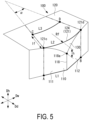
FIG. 5 is a perspective view of the molding die according to an embodiment of the present disclosure. -
FIG. 6 is a horizontal cross-sectional view at each height position of the molding die according to an embodiment of the present disclosure. -
FIG. 7 is a plan view of the molding die according to an embodiment of the present disclosure. -
FIG. 8 is a perspective view illustrating a shaping method according to an embodiment of the present disclosure. -
FIG. 9 is a graph illustrating a relationship between a relationship position s between a position s and an angle θ and a change rate dθ/ds of the angle. -
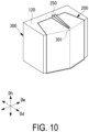
FIG. 10 is a perspective view illustrating a state after shaping according to Comparative Example 1. -
FIG. 11 is a graph showing a relationship between the relationship position s between the position s and the angle θ and the change rate dθ/ds of the angle (Comparative Example 1). -
FIG. 12 is a perspective view illustrating a state after shaping according to Comparative Example 2. -
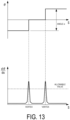
FIG. 13 is a graph showing a relationship between the relationship position s between the position s and the angle θ and the change rate dθ/ds of the angle (Comparative Example 2). - Hereinafter, an embodiment of a molding die and a shaping method according to the present disclosure will be described with reference to the drawings.
- In the following description, terms such as a height direction Dh (first direction), a depth direction Dd (second direction), and a width direction Dw (third direction), as well as terms such as upward and downward are used for convenience of description, and do not necessarily limit an orientation of an actual object.
- Here, the height direction Dh, the depth direction Dd, and the width direction Dw are orthogonal to one another.
- A molding die 100 is for shaping a laminate 200 (charge) including a plurality of laminated fiber sheets into a kink shape.
- The fiber sheet includes, for example, a fiber base material aligned such that the fiber direction becomes parallel to the longitudinal direction of the fiber sheet, and a resin impregnated into the fiber base material.
- As the fiber base material, carbon fiber, glass fiber, or the like is used.
- As the resin impregnated into the fiber base material, a thermosetting resin that is cured by being heated, such as an epoxy resin, polyimide, polyurethane, or unsaturated polyester, is used. Alternatively, a thermoplastic resin, such as polyamide, polyethylene, polystyrene, and polyvinyl chloride, which are solidified through heating, may be used.
- As illustrated in
FIGS. 1 to 4 , themolding die 100 is a die including akink surface 110, aplacement surface 120, and atransitional surface 130. - The
kink surface 110 is a bent surface having a first kink surface 111 (surface on the left side inFIG. 3 ) and a second kink surface 112 (surface on the right side inFIG. 3 ), and is bent such that the position in the depth direction Dd changes along the width direction Dw. - Each of the
first kink surface 111 and thesecond kink surface 112 is a flat surface, and akink line 118 is a boundary line between the two surfaces. Here, thekink line 118 is a line (ridge line) extending along the height direction Dh and connecting atop end point 118a (first kink point) and abottom end point 118b (second kink point). - That is, the
kink surface 110 is a bent surface to which the flatfirst kink surface 111 and the flatsecond kink surface 112 are connected with thekink line 118 extending along the height direction Dh as a boundary line, and which is bent so as to protrude in the depth direction Dd (front side inFIG. 1 ) with thekink line 118 extending along the height direction Dh as a ridge line. - The upper side of the
first kink surface 111 has afirst boundary line 113 and a firsttop end line 115. Similarly, the upper side of thesecond kink surface 112 has asecond boundary line 114 and a secondtop end line 116. - Each of the
first boundary line 113 and thesecond boundary line 114 is a line (ridge line) connected to thetop end point 118a of thekink line 118, and is a bifurcated line that is separated from each other in the width direction Dw as it goes upward in the height direction Dh from thetop end point 118a. - The first
top end line 115 is a straight line (ridge line) connected to thefirst boundary line 113 and extends in the width direction Dw. Similarly, the secondtop end line 116 is a straight line (ridge line) connected to thesecond boundary line 114, and extends in the width direction Dw. - The
placement surface 120 is a flat surface intersecting thekink surface 110, and the normal direction substantially coincides with the height direction Dh. That is, theplacement surface 120 is a flat surface substantially orthogonal to thekink surface 110. - The side (side on the front side in
FIG. 1 ) in contact with/adjacent to thekink surface 110 of theplacement surface 120 is abending line 121. - The
bending line 121 is a line (ridge line) extending in the width direction Dw and connecting afirst end portion 121a (end portion on the left side inFIG. 3 ) and asecond end portion 121b (end portion on the right side inFIG. 3 ). Thebending line 121 convexly protrudes in the depth direction Dd (front side inFIG. 1 ) as a whole. - The
bending line 121 is positioned upper than thetop end point 118a of thekink line 118 in the height direction Dh. That is, thetop end point 118a is positioned between the bendingline 121 and thebottom end point 118b in the height direction Dh. At this time, the dimension along the height direction Dh from thebending line 121 to thetop end point 118a of thekink line 118 is defined as a height h (seeFIG. 5 ). - Such the
bending line 121 has a bendingstraight line 122, a bendingstraight line 123, and a bendingconvex line 124. - The bending
straight line 122 is a part of thebending line 121 in a straight shape including thefirst end portion 121a, and coincides with the firsttop end line 115 of thefirst kink surface 111. That is, the bendingstraight line 122 and the firsttop end line 115 are the same straight line. Therefore, the bendingstraight line 122 is also connected to thefirst boundary line 113. Here, a boundary point (connection point) between the bendingstraight line 122 and thefirst boundary line 113 is defined as afirst intersection 121c. Thefirst intersection 121c is positioned closer to thefirst end portion 121a relative to thetop end point 118a in the width direction Dw. - The bending
straight line 123 is a part of thebending line 121 in a straight shape including thesecond end portion 121b, and coincides with the secondtop end line 116 of thesecond kink surface 112. That is, the bendingstraight line 123 and the secondtop end line 116 are the same straight line. Therefore, the bendingstraight line 123 is also connected to thesecond boundary line 114. Here, a boundary point (connection point) between the bendingstraight line 123 and thesecond boundary line 114 is defined as asecond intersection 121d. Thesecond intersection 121d is positioned closer to thesecond end portion 121b relative to thetop end point 118a in the width direction Dw. - The bending
convex line 124 is a part of thebending line 121 between thefirst intersection 121c and thesecond intersection 121d. - The bending
convex line 124 is a curved line convexly protruding in the depth direction Dd (front side inFIG. 1 ). The curve is preferably a continuous smooth line, but may be discontinuous (for example, stepwise) in a microscopic view. This curve has a predetermined radius of curvature, for example, an arc having a radius Rf (seeFIG. 5 ). - The
transitional surface 130 is a curved surface surrounded by the bendingconvex line 124, thefirst boundary line 113, and thesecond boundary line 114. - That is, the
transitional surface 130 is a substantially triangular curved surface connected to theplacement surface 120, thefirst kink surface 111, and thesecond kink surface 112. -
FIG. 6 illustrates horizontal cross-sectional views (cross-sectional views taken along planes extending in the depth direction Dd and the width direction Dw) of the molding die 100 in a plurality of different positions H1, H2, and H3 in the height direction Dh. - As illustrated in
FIG. 6 , thetransitional surface 130 is a curved surface in which a curve having a shape following the shape of the bendingconvex line 124 gradually decreases in length (circumferential length) toward thetop end point 118a of thekink line 118. The lowermost part of thetransitional surface 130 is a point coinciding with thetop end point 118a of thekink line 118. - The above-described circumferential length is preferably gradually changed. Therefore, the
first boundary line 113 and thesecond boundary line 114 are preferably smooth curves. Specifically, as illustrated inFIG. 3 , thefirst boundary line 113 is preferably a smooth curve convexly protruding toward thesecond end portion 121b, and thesecond boundary line 114 is preferably a smooth curve convexly protruding toward thefirst end portion 121a. - As illustrated in
FIG. 5 , the dimension along the height direction Dh from thebending line 121 to thetop end point 118a of thekink line 118 is the height h. The bendingconvex line 124 is, for example, an arc having the radius Rf. Hereinafter, a method of determining the height h and the radius Rf will be described. - The height h and the radius Rf are determined based on the "allowable value of dθ/ds" depending on the material properties (type of fiber base material, type of resin, density between fiber base materials, and the like) of the laminate 200 and the fiber sheet.
- First, dθ/ds will be described.
- As illustrated in
FIG. 7 , when a curve S extending from thefirst end portion 121a as a starting point toward thesecond end portion 121b along thebending line 121 is considered, dθ/ds is a change rate of an angle of a normal line (normal line with respect to the bending line 121) when moving by a minute distance ds from a position s1 to a position s2. In other words, dθ/ds is a ratio of a change amount dθ of the angle when the angle of a normal line Ns1 at the position s1 is compared with the angle of a normal line Ns2 at the position s2 with respect to the minute distance ds. - Ts1 illustrated in
FIG. 7 is a tangent line with respect to thebending line 121 at the position s1, and Ts2 is a tangent line with respect to thebending line 121 at the position s2. - Since the bending line 121 (that is, the bending straight line 122) from the
first end portion 121a to thefirst intersection 121c and the bending line 121 (that is, the bending straight line 123) from thesecond intersection 121d to thesecond end portion 121b are straight lines, dθ/ds = 0 (zero) is true. Since the bending line 121 (that is, the bending convex line 124) from thefirst intersection 121c to thesecond intersection 121d is a curved line (for example, an arc), |dθ/ds| > 0 is true. - A value obtained by integrating the change amount dθ of the angle from the
first intersection 121c to thesecond intersection 121d at the position s is an angle α. - Based on the above, the "allowable value of dθ/ds" is a limit value of the change rate of the angle at which, in consideration of the compressive stress locally acting on the fiber sheet when the change rate of the angle is dθ/ds and the relaxation of the compressive stress due to the shear deformation of the fiber sheet, the laminate 200 and the fiber sheet are not wrinkled based on appearance, even when subject to the compressive stress and shear deformation, and the fiber sheets are not shifted in the
laminate 200. - For example, when the change rate of the angle is equal to or less than the allowable value of dθ/ds, even if a local compressive force acts on the laminate 200 and the fiber sheet, only the resin between the fiber base materials is compressed within a range that is not wrinkled.
- The above shear deformation is applied to relax the compressive stress acting on the fiber sheet by stretching, in the width direction Dw, the compressed fiber sheet.
- As illustrated in
FIG. 5 , when a position spaced apart by a distance lf from thefirst intersection 121c along a normal line (normal line with respect to the bending line 121) at thefirst intersection 121c is defined as a point C, and a position spaced apart by the distance lf from thesecond intersection 121d along a normal line (normal line with respect to the bending line 121) at thesecond intersection 121d is defined as a point D, a length of a curve substantially parallel to thebending line 121 from the point C to the point D is defined as L3. The distance lf will be described below. - At this time, the difference between L2 and L3 is expressed by the following
Equation 1.
- dθ/ds is expressed by the following
Equation 2 based onEquation 1.
- Since dθ/ds is determined by the material properties and the angle α is determined by the angle between the
first kink surface 111 and thesecond kink surface 112, the radius Rf according to the allowable value of dθ/ds can be determined usingEquation 2. - As illustrated in
FIG. 5 , when an intersection of a line extending downward along the height direction Dh from thefirst intersection 121c and the bottom edge of thefirst kink surface 111 is defined as a point A, and an intersection of a line extending downward along the height direction Dh from thesecond intersection 121d and the bottom edge of thesecond kink surface 112 is defined as a point B, a length of the bottom edge (bending line) of thekink surface 110 from the point A to the point B is defined as L1. The length (that is, the length of the bending convex line 124) of thebending line 121 from thefirst intersection 121c to thesecond intersection 121d is defined as L2. - At this time, the difference between L1 and L2 is expressed by the following Equation 3.

- Here, the angle α is an angle between the normal line (normal line with respect to the bending line 121) at the
first intersection 121c and the normal line (normal line with respect to the bending line 121) at thesecond intersection 121d, and depends on the angle between thefirst kink surface 111 and thesecond kink surface 112. - dθ/ds is expressed by the following Equation 4 based on Equation 3.

- Since dθ/ds is determined by the material properties and the angle α is determined by the angle between the
first kink surface 111 and thesecond kink surface 112, the height h according to the allowable value of dθ/ds can be determined using Equation 4. - As illustrated in
FIG. 8 , first, the laminate 200 is laid on thekink surface 110. - By laying the laminate 200 onto the
kink surface 110, the laminate 200 is bent following thekink surface 110, and akink line portion 230 extending along thekink line 118 provided on thekink surface 110 is formed in thelaminate 200. - At this time, a part of the laminate 200 in surface contact with the
kink surface 110 is defined as afirst portion 201, and a part of the laminate 200 protruding upward from thekink surface 110 is defined as asecond portion 202. The dimension along the height direction Dh of thesecond portion 202 is the distance lf. - Next, the
second portion 202 of the laminate 200 is bent toward theplacement surface 120 along thebending line 121 to be placed on theplacement surface 120. - In the process of bending the
second portion 202 toward theplacement surface 120, both sides of thesecond portion 202 are close to the center, and the laminate 200 (fiber sheet) corresponding to thesecond portion 202 is compressed in the width direction Dw to generate strain. - However, as illustrated in
FIG. 9 , since the angle θ of the normal line continuously and gradually changes from thefirst intersection 121c to thesecond intersection 121d on thebending line 121, the change rate dθ/ds of the angle maintains a value equal to or less than the allowable value from thefirst intersection 121c to thesecond intersection 121d. That is, since there is a range between thefirst intersection 121c and thesecond intersection 121d, the change in the angle θ of the normal necessary for giving the kink shape to the laminate 200 is dispersed within the range, and the change rate dθ/ds of the angle is reduced as a whole. - Due to this, the total strain amount in the width direction Dw that should be generated in the laminate 200 (fiber sheet) corresponding to the
second portion 202 is dispersed in the range between thefirst intersection 121c and thesecond intersection 121d, and therefore the total strain amount is avoided from locally concentrating, and the laminate 200 (fiber sheet) is less likely to wrinkle. - Since the graph illustrated in
FIG. 9 assumes a case where the bendingconvex line 124 is an arc having the radius Rf, the angle change rate dθ/ds is constant in range between thefirst intersection 121c and thesecond intersection 121d. - However, as long as the change rate dθ/ds of the angle becomes equal to or less than the allowable value in the same range, the change rate dθ/ds of the angle may necessarily be not constant. That is, the radius of curvature of the bending
convex line 124 may be changed in the same range. - If a molding die 300 (without equivalents of the
first boundary line 113, thesecond boundary line 114, and the bendingconvex line 124 of the molding die 100) as illustrated inFIG. 10 is used, the change in the angle θ of the normal line necessary for giving the kink shape to the laminate 200 is concentrated on avertex 301. - Therefore, as illustrated in
FIG. 11 , the change rate dθ/ds of the angle has a peak greatly exceeding the allowable value near thevertex 301. As a result, the total strain amount is locally concentrated, andwrinkles 250 are generated in the laminate 200 (fiber sheet). - If a molding die 400 (with all equivalents of the
first boundary line 113, thesecond boundary line 114, and the bendingconvex line 124 of the molding die 100 being straight lines) as illustrated inFIG. 12 is used, the change in the angle θ of the normal line necessary for giving the kink shape to the laminate 200 is concentrated on avertex 401 and avertex 402. - Therefore, as illustrated in
FIG. 13 , the change rate dθ/ds of the angle peaks near thevertex 401 and thevertex 402. Each peak has a lower numerical value than that in the case of Comparative Example 1, but exceeds the allowable value. As a result, the total strain amount is locally concentrated, and thewrinkles 250 are generated in the laminate 200 (fiber sheet). - With the present embodiment, the following effects are achieved.
- Since the
bending line 121 between thefirst intersection 121c and thesecond intersection 121d convexly protrudes toward thekink line 118 in the depth direction Dd, when the laminate 200 laid on thekink surface 110 is bent to be placed on theplacement surface 120, the total strain amount that should be generated in the laminate 200 by the laminate 200 being compressed in the width direction Dw on theplacement surface 120 is dispersed in a wide range (range wider than a case where at least the bending line is bent at one point (vertex 301) or two points (vertex 401 and vertex 402)) of thebending line 121 between thefirst intersection 121c and thesecond intersection 121d. Therefore, the total strain amount is avoided from locally concentrating, and the laminate 200 on theplacement surface 120 is less likely to wrinkle. - When the
bending line 121 between thefirst intersection 121c and thesecond intersection 121d is a smooth curve, the change rate dθ/ds of the angle with respect to the minute distance ds on thebending line 121 between thefirst intersection 121c and thesecond intersection 121d can be made smooth. Therefore, the change rate dθ/ds is avoided from locally increasing, and the laminate placed on theplacement surface 120 less likely to wrinkle. - Since the
kink surface 110 is bent with thekink line 118 as a boundary and has thefirst boundary line 113 and thesecond boundary line 114, it is possible to provide a range (bending convex line 124) convexly protruding as described above in thebending line 121 while securing, on thekink surface 110, a flat surface for forming, in the laminate 200, a flat interface with which other components are in contact. - When the
first boundary line 113 is a smooth curve convexly protruding toward thesecond intersection 121d and thesecond boundary line 114 is a smooth curve convexly protruding toward thefirst intersection 121c, it is possible to smooth the change rate in the distance from thefirst boundary line 113 to thesecond boundary line 114 in the height direction Dh, that is, the change rate in the circumferential length in the height direction Dh on thetransitional surface 130. Therefore, the change rate is avoided from locally increasing, and the laminate 200 on thetransitional surface 130 is less likely to wrinkle. - The present embodiment described above is understood as follows, for example.
- That is, the molding die (100) according to a first aspect of the present disclosure is a molding die for bending the laminate (200) formed by stacking a plurality of fiber sheets, the molding die (100) including: the kink surface (110) on which the laminate is laid; and the placement surface (120) intersecting the kink surface and on which the laminate is placed by bending the laminate laid on the kink surface, in which the kink surface is bent so as to protrude in the second direction (Dd) orthogonal to the first direction (Dh) with the kink line (118) extending along the first direction connecting the first kink point (118a) and the second kink point (118b) as a boundary, the placement surface has a normal direction substantially coinciding with the first direction and has the bending line (121) extending in the third direction (Dw) orthogonal to the first direction and the second direction, the kink surface has the first boundary line (113) connecting the first intersection (121c) on the bending line and the first kink point, and the second boundary line (114) connecting the second intersection (121d) on the bending line and the first kink point, the first intersection is positioned closer to one end (121a) of the bending line relative to the first kink point in the third direction, the second intersection is positioned closer to the other end (121b) of the bending line relative to the first kink point in the third direction, the first kink point is positioned between the first intersection and the second intersection and the second kink point in the first direction, and the bending line between the first intersection and the second intersection convexly protrudes toward the kink line in the second direction.
- According to a molding die according to the present aspect, since the bending line between the first intersection and the second intersection convexly protrudes toward the kink line in the second direction, when the laminate laid on the kink surface is bent to be placed on the placement surface, the total strain amount that should be generated in the laminate by the laminate being compressed in the third direction on the placement surface is dispersed in a wide range (range wider than a case where at least the bending line is bent at one point or two points) of the bending line between the first intersection and the second intersection. Therefore, the total strain amount is avoided from locally concentrating, and the laminate placed on the placement surface is less likely to wrinkle.
- Since the kink surface is bent with the kink line as a boundary and has the first boundary line and the second boundary line, it is possible to provide a range convexly protruding as described above in the bending line while securing, on the kink surface, a flat surface for forming, in the laminate, a flat interface with which other components are in contact.
- In a molding die according to a second aspect of the present disclosure, in the first aspect, the bending line between the first intersection and the second intersection is a smooth curve convexly protruding toward the kink line.
- According to the molding die according to the present aspect, since the bending line between the first intersection and the second intersection is a smooth curve convexly protruding toward the kink line, the change rate of the angle with respect to the minute distance on the bending line between the first intersection and the second intersection can be made smooth. Therefore, the change rate is avoided from locally increasing, and the laminate placed on the placement surface is less likely to wrinkle.
- In a molding die according to a third aspect of the present disclosure, in the second aspect, the bending line between the first intersection and the second intersection is an arc.
- According to the molding die according to the present aspect, since the bending line between the first intersection and the second intersection is an arc, the change rate of the angle with respect to a minute distance on the bending line between the first intersection and the second intersection can be made constant. Therefore, the change rate is avoided from locally increasing, and the laminate placed on the placement surface is less likely to wrinkle.
- In a molding die according to a fourth aspect of the present disclosure, in any of the first to third aspects, the first boundary line is a smooth curve convexly protruding toward the second intersection, and the second boundary line is a smooth curve convexly protruding toward the first intersection.
- According to the molding die according to the present aspect, since the first boundary line is a smooth curve convexly protruding toward the second intersection, and the second boundary line is a smooth curve convexly protruding toward the first intersection, it is possible to smooth the change rate in the distance from the first boundary line to the second boundary line in the first direction, that is, the change rate in the circumferential length in the first direction on the surface (hereinafter, called the "transitional surface") surrounded by the three lines of the bending line, the first boundary line, and the second boundary line. Therefore, the change rate is avoided from locally increasing, and the laminate placed on the transitional surface is less likely to wrinkle.
- A shaping method according to a fifth aspect of the present disclosure is a shaping method for shaping the laminate using the molding die described in any of the first to fourth aspects, the shaping method including: laying the laminate on the kink surface; and bending, toward the placement surface along the bending line, the laminate laid on the kink surface.
-
- 100 Molding die
- 110 Kink surface
- 111 First kink surface
- 112 Second kink surface
- 113 First boundary line
- 114 Second boundary line
- 115 First top end line
- 116 Second top end line
- 118 Kink line
- 118a Top end point (first kink point)
- 118b Bottom end point (second kink point)
- 120 Placement surface
- 121 Bending line
- 121a First end portion
- 121b Second end portion
- 121c First intersection
- 121d Second intersection
- 122 Bending straight line (bending
line 121 from first end portion to first intersection) - 123 Bending straight line (bending
line 121 from second intersection to second end portion) - 124 Bending convex line (bending
line 121 from first intersection to second intersection) - 130 Transitional surface
- 200 Laminate
- 201 First portion
- 202 Second portion
- 230 Kink line portion
- Dh Height direction (first direction)
- Dd Depth direction (second direction)
- Dw Width direction (third direction)
Claims (5)
- A molding die for bending a laminate formed by stacking a plurality of fiber sheets, the molding die comprising:a kink surface on which the laminate is laid; ana placement surface intersecting the kink surface and on which the laminate is placed by bending the laminate laid on the kink surface, whereinthe kink surface is bent so as to protrude in a second direction orthogonal to a first direction, with a kink line extending along the first direction connecting a first kink point and a second kink point as a boundary,the placement surface has a normal direction substantially coinciding with the first direction and has a bending line extending in a third direction orthogonal to the first direction and the second direction,the kink surface has a first boundary line connecting a first intersection on the bending line and the first kink point, and a second boundary line connecting a second intersection on the bending line and the first kink point,the first intersection is positioned closer to one end of the bending line relative to the first kink point in the third direction,the second intersection is positioned closer to an other end of the bending line relative to the first kink point in the third direction,the first kink point is positioned between the first intersection and the second intersection and the second kink point in the first direction, andthe bending line between the first intersection and the second intersection convexly protrudes toward the kink line in the second direction.
- The molding die according to claim 1, wherein the bending line between the first intersection and the second intersection is a smooth curve convexly protruding toward the kink line.
- The molding die according to claim 2, wherein the bending line between the first intersection and the second intersection is an arc.
- The molding die according to claim 1 or 2, whereinthe first boundary line is a smooth curve convexly protruding toward the second intersection, andthe second boundary line is a smooth curve convexly protruding toward the first intersection.
- A shaping method for shaping the laminate using the molding die described in claim 1, the shaping method comprising:laying the laminate on the kink surface; andbending, toward the placement surface along the bending line, the laminate laid on the kink surface.
Applications Claiming Priority (1)
| Application Number | Priority Date | Filing Date | Title |
|---|---|---|---|
| JP2022209957A JP7822925B2 (en) | 2022-12-27 | 2022-12-27 | Mold and shaping method |
Publications (2)
| Publication Number | Publication Date |
|---|---|
| EP4393686A1 true EP4393686A1 (en) | 2024-07-03 |
| EP4393686B1 EP4393686B1 (en) | 2025-07-02 |
Family
ID=89322135
Family Applications (1)
| Application Number | Title | Priority Date | Filing Date |
|---|---|---|---|
| EP23219760.8A Active EP4393686B1 (en) | 2022-12-27 | 2023-12-22 | Molding die and shaping method |
Country Status (3)
| Country | Link |
|---|---|
| US (1) | US12441033B2 (en) |
| EP (1) | EP4393686B1 (en) |
| JP (1) | JP7822925B2 (en) |
Citations (6)
| Publication number | Priority date | Publication date | Assignee | Title |
|---|---|---|---|---|
| JP4773713B2 (en) | 2004-11-17 | 2011-09-14 | 三菱重工業株式会社 | Shape determination method of mold model |
| US8795567B2 (en) | 2010-09-23 | 2014-08-05 | The Boeing Company | Method for fabricating highly contoured composite stiffeners with reduced wrinkling |
| JP2016124125A (en) * | 2014-12-26 | 2016-07-11 | 東レ株式会社 | Method for producing fiber-reinforced plastic |
| US20170297317A1 (en) * | 2016-04-18 | 2017-10-19 | The Boeing Company | Formation of composite laminates having one or more divergent flanges |
| EP3998151A1 (en) * | 2019-09-26 | 2022-05-18 | Mitsubishi Heavy Industries, Ltd. | Composite material component shaping method and charge |
| EP4000911A1 (en) * | 2019-11-26 | 2022-05-25 | Mitsubishi Heavy Industries, Ltd. | Molding method and molding die |
Family Cites Families (3)
| Publication number | Priority date | Publication date | Assignee | Title |
|---|---|---|---|---|
| JPH06254891A (en) * | 1993-02-26 | 1994-09-13 | Nitto Boseki Co Ltd | Mold for molding composite material sheet and molding method |
| WO2019178072A1 (en) | 2018-03-12 | 2019-09-19 | Cytec Industries Inc. | Fabrication of three-dimensional composite structures |
| WO2021157082A1 (en) | 2020-02-07 | 2021-08-12 | 三菱重工業株式会社 | Method for manufacturing composite-material structure body, method for manufacturing laminated body, laminated body, and lamination mold |
-
2022
- 2022-12-27 JP JP2022209957A patent/JP7822925B2/en active Active
-
2023
- 2023-12-22 EP EP23219760.8A patent/EP4393686B1/en active Active
- 2023-12-27 US US18/397,207 patent/US12441033B2/en active Active
Patent Citations (6)
| Publication number | Priority date | Publication date | Assignee | Title |
|---|---|---|---|---|
| JP4773713B2 (en) | 2004-11-17 | 2011-09-14 | 三菱重工業株式会社 | Shape determination method of mold model |
| US8795567B2 (en) | 2010-09-23 | 2014-08-05 | The Boeing Company | Method for fabricating highly contoured composite stiffeners with reduced wrinkling |
| JP2016124125A (en) * | 2014-12-26 | 2016-07-11 | 東レ株式会社 | Method for producing fiber-reinforced plastic |
| US20170297317A1 (en) * | 2016-04-18 | 2017-10-19 | The Boeing Company | Formation of composite laminates having one or more divergent flanges |
| EP3998151A1 (en) * | 2019-09-26 | 2022-05-18 | Mitsubishi Heavy Industries, Ltd. | Composite material component shaping method and charge |
| EP4000911A1 (en) * | 2019-11-26 | 2022-05-25 | Mitsubishi Heavy Industries, Ltd. | Molding method and molding die |
Also Published As
| Publication number | Publication date |
|---|---|
| EP4393686B1 (en) | 2025-07-02 |
| US20240208162A1 (en) | 2024-06-27 |
| US12441033B2 (en) | 2025-10-14 |
| JP2024093524A (en) | 2024-07-09 |
| JP7822925B2 (en) | 2026-03-03 |
Similar Documents
| Publication | Publication Date | Title |
|---|---|---|
| CN107878726B (en) | Advanced Variable Radius Laminated Composite Radius Filler | |
| CN101795937B (en) | Improvements in elongate composite structural member | |
| RU2492107C2 (en) | Stringer (versions), method of developing stringer model, aerospace device (versions), aircraft (versions) and computer | |
| CN106142723B (en) | System and method for forming composite materials | |
| EP2689918B1 (en) | Laminated composite bending and stiffening members with reinforcement by inter-laminar metal sheets | |
| EP3263320B1 (en) | Wrinkle reduction in formed composite laminates | |
| US10124568B2 (en) | Method of manufacturing a curved profile made of composite material from a rectilinear preform of fiber plies | |
| EP2300314B1 (en) | Apparatus and method for forming a ramped stiffener | |
| EP4393686B1 (en) | Molding die and shaping method | |
| US12285901B2 (en) | Composite material structure body production method, layered body production method, layered body, and layered form | |
| US10994823B2 (en) | Beaded panels and method of forming beaded panels | |
| JP2011240925A5 (en) | ||
| CN110181881B (en) | Composite structural elements | |
| US11993030B2 (en) | Composite material component shaping method and charge | |
| EP4272938A1 (en) | Laminated body and forming method | |
| JP7392000B2 (en) | Method for manufacturing composite structures | |
| EP4656364A1 (en) | Composite radius fillers, assemblies including composite radius fillers, and systems and methods of forming the same | |
| WO2023072363A1 (en) | Composite sandwich slope | |
| EP1375344A1 (en) | Winglet leading edge and its manufacturing method |
Legal Events
| Date | Code | Title | Description |
|---|---|---|---|
| PUAI | Public reference made under article 153(3) epc to a published international application that has entered the european phase |
Free format text: ORIGINAL CODE: 0009012 |
|
| STAA | Information on the status of an ep patent application or granted ep patent |
Free format text: STATUS: THE APPLICATION HAS BEEN PUBLISHED |
|
| AK | Designated contracting states |
Kind code of ref document: A1 Designated state(s): AL AT BE BG CH CY CZ DE DK EE ES FI FR GB GR HR HU IE IS IT LI LT LU LV MC ME MK MT NL NO PL PT RO RS SE SI SK SM TR |
|
| STAA | Information on the status of an ep patent application or granted ep patent |
Free format text: STATUS: REQUEST FOR EXAMINATION WAS MADE |
|
| 17P | Request for examination filed |
Effective date: 20240919 |
|
| RBV | Designated contracting states (corrected) |
Designated state(s): AL AT BE BG CH CY CZ DE DK EE ES FI FR GB GR HR HU IE IS IT LI LT LU LV MC ME MK MT NL NO PL PT RO RS SE SI SK SM TR |
|
| GRAP | Despatch of communication of intention to grant a patent |
Free format text: ORIGINAL CODE: EPIDOSNIGR1 |
|
| STAA | Information on the status of an ep patent application or granted ep patent |
Free format text: STATUS: GRANT OF PATENT IS INTENDED |
|
| INTG | Intention to grant announced |
Effective date: 20250207 |
|
| GRAS | Grant fee paid |
Free format text: ORIGINAL CODE: EPIDOSNIGR3 |
|
| GRAA | (expected) grant |
Free format text: ORIGINAL CODE: 0009210 |
|
| STAA | Information on the status of an ep patent application or granted ep patent |
Free format text: STATUS: THE PATENT HAS BEEN GRANTED |
|
| AK | Designated contracting states |
Kind code of ref document: B1 Designated state(s): AL AT BE BG CH CY CZ DE DK EE ES FI FR GB GR HR HU IE IS IT LI LT LU LV MC ME MK MT NL NO PL PT RO RS SE SI SK SM TR |
|
| REG | Reference to a national code |
Ref country code: GB Ref legal event code: FG4D |
|
| REG | Reference to a national code |
Ref country code: CH Ref legal event code: EP |
|
| REG | Reference to a national code |
Ref country code: DE Ref legal event code: R096 Ref document number: 602023004533 Country of ref document: DE |
|
| REG | Reference to a national code |
Ref country code: IE Ref legal event code: FG4D |
|
| REG | Reference to a national code |
Ref country code: NL Ref legal event code: MP Effective date: 20250702 |
|
| PG25 | Lapsed in a contracting state [announced via postgrant information from national office to epo] |
Ref country code: PT Free format text: LAPSE BECAUSE OF FAILURE TO SUBMIT A TRANSLATION OF THE DESCRIPTION OR TO PAY THE FEE WITHIN THE PRESCRIBED TIME-LIMIT Effective date: 20251103 |
|
| PG25 | Lapsed in a contracting state [announced via postgrant information from national office to epo] |
Ref country code: NL Free format text: LAPSE BECAUSE OF FAILURE TO SUBMIT A TRANSLATION OF THE DESCRIPTION OR TO PAY THE FEE WITHIN THE PRESCRIBED TIME-LIMIT Effective date: 20250702 |
|
| REG | Reference to a national code |
Ref country code: AT Ref legal event code: MK05 Ref document number: 1808783 Country of ref document: AT Kind code of ref document: T Effective date: 20250702 |
|
| PG25 | Lapsed in a contracting state [announced via postgrant information from national office to epo] |
Ref country code: IS Free format text: LAPSE BECAUSE OF FAILURE TO SUBMIT A TRANSLATION OF THE DESCRIPTION OR TO PAY THE FEE WITHIN THE PRESCRIBED TIME-LIMIT Effective date: 20251102 |
|
| PGFP | Annual fee paid to national office [announced via postgrant information from national office to epo] |
Ref country code: DE Payment date: 20251028 Year of fee payment: 3 |
|
| PG25 | Lapsed in a contracting state [announced via postgrant information from national office to epo] |
Ref country code: NO Free format text: LAPSE BECAUSE OF FAILURE TO SUBMIT A TRANSLATION OF THE DESCRIPTION OR TO PAY THE FEE WITHIN THE PRESCRIBED TIME-LIMIT Effective date: 20251002 |
|
| REG | Reference to a national code |
Ref country code: LT Ref legal event code: MG9D |
|
| PG25 | Lapsed in a contracting state [announced via postgrant information from national office to epo] |
Ref country code: AT Free format text: LAPSE BECAUSE OF FAILURE TO SUBMIT A TRANSLATION OF THE DESCRIPTION OR TO PAY THE FEE WITHIN THE PRESCRIBED TIME-LIMIT Effective date: 20250702 |
|
| PG25 | Lapsed in a contracting state [announced via postgrant information from national office to epo] |
Ref country code: FI Free format text: LAPSE BECAUSE OF FAILURE TO SUBMIT A TRANSLATION OF THE DESCRIPTION OR TO PAY THE FEE WITHIN THE PRESCRIBED TIME-LIMIT Effective date: 20250702 |
|
| PG25 | Lapsed in a contracting state [announced via postgrant information from national office to epo] |
Ref country code: HR Free format text: LAPSE BECAUSE OF FAILURE TO SUBMIT A TRANSLATION OF THE DESCRIPTION OR TO PAY THE FEE WITHIN THE PRESCRIBED TIME-LIMIT Effective date: 20250702 |
|
| PGFP | Annual fee paid to national office [announced via postgrant information from national office to epo] |
Ref country code: FR Payment date: 20251110 Year of fee payment: 3 |
|
| PG25 | Lapsed in a contracting state [announced via postgrant information from national office to epo] |
Ref country code: GR Free format text: LAPSE BECAUSE OF FAILURE TO SUBMIT A TRANSLATION OF THE DESCRIPTION OR TO PAY THE FEE WITHIN THE PRESCRIBED TIME-LIMIT Effective date: 20251003 |
|
| PG25 | Lapsed in a contracting state [announced via postgrant information from national office to epo] |
Ref country code: SE Free format text: LAPSE BECAUSE OF FAILURE TO SUBMIT A TRANSLATION OF THE DESCRIPTION OR TO PAY THE FEE WITHIN THE PRESCRIBED TIME-LIMIT Effective date: 20250702 Ref country code: CZ Free format text: LAPSE BECAUSE OF FAILURE TO SUBMIT A TRANSLATION OF THE DESCRIPTION OR TO PAY THE FEE WITHIN THE PRESCRIBED TIME-LIMIT Effective date: 20250702 |
|
| PG25 | Lapsed in a contracting state [announced via postgrant information from national office to epo] |
Ref country code: LV Free format text: LAPSE BECAUSE OF FAILURE TO SUBMIT A TRANSLATION OF THE DESCRIPTION OR TO PAY THE FEE WITHIN THE PRESCRIBED TIME-LIMIT Effective date: 20250702 |
|
| PG25 | Lapsed in a contracting state [announced via postgrant information from national office to epo] |
Ref country code: PL Free format text: LAPSE BECAUSE OF FAILURE TO SUBMIT A TRANSLATION OF THE DESCRIPTION OR TO PAY THE FEE WITHIN THE PRESCRIBED TIME-LIMIT Effective date: 20250702 Ref country code: BG Free format text: LAPSE BECAUSE OF FAILURE TO SUBMIT A TRANSLATION OF THE DESCRIPTION OR TO PAY THE FEE WITHIN THE PRESCRIBED TIME-LIMIT Effective date: 20250702 |
|
| PG25 | Lapsed in a contracting state [announced via postgrant information from national office to epo] |
Ref country code: RS Free format text: LAPSE BECAUSE OF FAILURE TO SUBMIT A TRANSLATION OF THE DESCRIPTION OR TO PAY THE FEE WITHIN THE PRESCRIBED TIME-LIMIT Effective date: 20251002 |
|
| PG25 | Lapsed in a contracting state [announced via postgrant information from national office to epo] |
Ref country code: ES Free format text: LAPSE BECAUSE OF FAILURE TO SUBMIT A TRANSLATION OF THE DESCRIPTION OR TO PAY THE FEE WITHIN THE PRESCRIBED TIME-LIMIT Effective date: 20250702 |
|
| PG25 | Lapsed in a contracting state [announced via postgrant information from national office to epo] |
Ref country code: RO Free format text: LAPSE BECAUSE OF FAILURE TO SUBMIT A TRANSLATION OF THE DESCRIPTION OR TO PAY THE FEE WITHIN THE PRESCRIBED TIME-LIMIT Effective date: 20250702 |
|
| PG25 | Lapsed in a contracting state [announced via postgrant information from national office to epo] |
Ref country code: SM Free format text: LAPSE BECAUSE OF FAILURE TO SUBMIT A TRANSLATION OF THE DESCRIPTION OR TO PAY THE FEE WITHIN THE PRESCRIBED TIME-LIMIT Effective date: 20250702 |
|
| PG25 | Lapsed in a contracting state [announced via postgrant information from national office to epo] |
Ref country code: DK Free format text: LAPSE BECAUSE OF FAILURE TO SUBMIT A TRANSLATION OF THE DESCRIPTION OR TO PAY THE FEE WITHIN THE PRESCRIBED TIME-LIMIT Effective date: 20250702 |
|
| PG25 | Lapsed in a contracting state [announced via postgrant information from national office to epo] |
Ref country code: IT Free format text: LAPSE BECAUSE OF FAILURE TO SUBMIT A TRANSLATION OF THE DESCRIPTION OR TO PAY THE FEE WITHIN THE PRESCRIBED TIME-LIMIT Effective date: 20250702 |
|
| PG25 | Lapsed in a contracting state [announced via postgrant information from national office to epo] |
Ref country code: EE Free format text: LAPSE BECAUSE OF FAILURE TO SUBMIT A TRANSLATION OF THE DESCRIPTION OR TO PAY THE FEE WITHIN THE PRESCRIBED TIME-LIMIT Effective date: 20250702 Ref country code: SK Free format text: LAPSE BECAUSE OF FAILURE TO SUBMIT A TRANSLATION OF THE DESCRIPTION OR TO PAY THE FEE WITHIN THE PRESCRIBED TIME-LIMIT Effective date: 20250702 |
|
| PLBE | No opposition filed within time limit |
Free format text: ORIGINAL CODE: 0009261 |
|
| STAA | Information on the status of an ep patent application or granted ep patent |
Free format text: STATUS: NO OPPOSITION FILED WITHIN TIME LIMIT |