EP4393681A1 - 3d printer head using local heating method - Google Patents
3d printer head using local heating method Download PDFInfo
- Publication number
- EP4393681A1 EP4393681A1 EP22940502.2A EP22940502A EP4393681A1 EP 4393681 A1 EP4393681 A1 EP 4393681A1 EP 22940502 A EP22940502 A EP 22940502A EP 4393681 A1 EP4393681 A1 EP 4393681A1
- Authority
- EP
- European Patent Office
- Prior art keywords
- heating
- syringe
- printer head
- local heating
- heating type
- Prior art date
- Legal status (The legal status is an assumption and is not a legal conclusion. Google has not performed a legal analysis and makes no representation as to the accuracy of the status listed.)
- Granted
Links
Images



Classifications
-
- B—PERFORMING OPERATIONS; TRANSPORTING
- B29—WORKING OF PLASTICS; WORKING OF SUBSTANCES IN A PLASTIC STATE IN GENERAL
- B29C—SHAPING OR JOINING OF PLASTICS; SHAPING OF MATERIAL IN A PLASTIC STATE, NOT OTHERWISE PROVIDED FOR; AFTER-TREATMENT OF THE SHAPED PRODUCTS, e.g. REPAIRING
- B29C64/00—Additive manufacturing, i.e. manufacturing of three-dimensional [3D] objects by additive deposition, additive agglomeration or additive layering, e.g. by 3D printing, stereolithography or selective laser sintering
- B29C64/20—Apparatus for additive manufacturing; Details thereof or accessories therefor
- B29C64/295—Heating elements
-
- B—PERFORMING OPERATIONS; TRANSPORTING
- B29—WORKING OF PLASTICS; WORKING OF SUBSTANCES IN A PLASTIC STATE IN GENERAL
- B29C—SHAPING OR JOINING OF PLASTICS; SHAPING OF MATERIAL IN A PLASTIC STATE, NOT OTHERWISE PROVIDED FOR; AFTER-TREATMENT OF THE SHAPED PRODUCTS, e.g. REPAIRING
- B29C64/00—Additive manufacturing, i.e. manufacturing of three-dimensional [3D] objects by additive deposition, additive agglomeration or additive layering, e.g. by 3D printing, stereolithography or selective laser sintering
- B29C64/10—Processes of additive manufacturing
- B29C64/106—Processes of additive manufacturing using only liquids or viscous materials, e.g. depositing a continuous bead of viscous material
- B29C64/112—Processes of additive manufacturing using only liquids or viscous materials, e.g. depositing a continuous bead of viscous material using individual droplets, e.g. from jetting heads
-
- B—PERFORMING OPERATIONS; TRANSPORTING
- B29—WORKING OF PLASTICS; WORKING OF SUBSTANCES IN A PLASTIC STATE IN GENERAL
- B29C—SHAPING OR JOINING OF PLASTICS; SHAPING OF MATERIAL IN A PLASTIC STATE, NOT OTHERWISE PROVIDED FOR; AFTER-TREATMENT OF THE SHAPED PRODUCTS, e.g. REPAIRING
- B29C64/00—Additive manufacturing, i.e. manufacturing of three-dimensional [3D] objects by additive deposition, additive agglomeration or additive layering, e.g. by 3D printing, stereolithography or selective laser sintering
- B29C64/10—Processes of additive manufacturing
- B29C64/106—Processes of additive manufacturing using only liquids or viscous materials, e.g. depositing a continuous bead of viscous material
- B29C64/118—Processes of additive manufacturing using only liquids or viscous materials, e.g. depositing a continuous bead of viscous material using filamentary material being melted, e.g. fused deposition modelling [FDM]
-
- B—PERFORMING OPERATIONS; TRANSPORTING
- B29—WORKING OF PLASTICS; WORKING OF SUBSTANCES IN A PLASTIC STATE IN GENERAL
- B29C—SHAPING OR JOINING OF PLASTICS; SHAPING OF MATERIAL IN A PLASTIC STATE, NOT OTHERWISE PROVIDED FOR; AFTER-TREATMENT OF THE SHAPED PRODUCTS, e.g. REPAIRING
- B29C64/00—Additive manufacturing, i.e. manufacturing of three-dimensional [3D] objects by additive deposition, additive agglomeration or additive layering, e.g. by 3D printing, stereolithography or selective laser sintering
- B29C64/20—Apparatus for additive manufacturing; Details thereof or accessories therefor
- B29C64/205—Means for applying layers
- B29C64/209—Heads; Nozzles
-
- B—PERFORMING OPERATIONS; TRANSPORTING
- B29—WORKING OF PLASTICS; WORKING OF SUBSTANCES IN A PLASTIC STATE IN GENERAL
- B29C—SHAPING OR JOINING OF PLASTICS; SHAPING OF MATERIAL IN A PLASTIC STATE, NOT OTHERWISE PROVIDED FOR; AFTER-TREATMENT OF THE SHAPED PRODUCTS, e.g. REPAIRING
- B29C64/00—Additive manufacturing, i.e. manufacturing of three-dimensional [3D] objects by additive deposition, additive agglomeration or additive layering, e.g. by 3D printing, stereolithography or selective laser sintering
- B29C64/30—Auxiliary operations or equipment
- B29C64/386—Data acquisition or data processing for additive manufacturing
- B29C64/393—Data acquisition or data processing for additive manufacturing for controlling or regulating additive manufacturing processes
-
- B—PERFORMING OPERATIONS; TRANSPORTING
- B33—ADDITIVE MANUFACTURING TECHNOLOGY
- B33Y—ADDITIVE MANUFACTURING, i.e. MANUFACTURING OF THREE-DIMENSIONAL [3D] OBJECTS BY ADDITIVE DEPOSITION, ADDITIVE AGGLOMERATION OR ADDITIVE LAYERING, e.g. BY 3D PRINTING, STEREOLITHOGRAPHY OR SELECTIVE LASER SINTERING
- B33Y10/00—Processes of additive manufacturing
-
- B—PERFORMING OPERATIONS; TRANSPORTING
- B33—ADDITIVE MANUFACTURING TECHNOLOGY
- B33Y—ADDITIVE MANUFACTURING, i.e. MANUFACTURING OF THREE-DIMENSIONAL [3D] OBJECTS BY ADDITIVE DEPOSITION, ADDITIVE AGGLOMERATION OR ADDITIVE LAYERING, e.g. BY 3D PRINTING, STEREOLITHOGRAPHY OR SELECTIVE LASER SINTERING
- B33Y30/00—Apparatus for additive manufacturing; Details thereof or accessories therefor
-
- B—PERFORMING OPERATIONS; TRANSPORTING
- B33—ADDITIVE MANUFACTURING TECHNOLOGY
- B33Y—ADDITIVE MANUFACTURING, i.e. MANUFACTURING OF THREE-DIMENSIONAL [3D] OBJECTS BY ADDITIVE DEPOSITION, ADDITIVE AGGLOMERATION OR ADDITIVE LAYERING, e.g. BY 3D PRINTING, STEREOLITHOGRAPHY OR SELECTIVE LASER SINTERING
- B33Y40/00—Auxiliary operations or equipment, e.g. for material handling
-
- B—PERFORMING OPERATIONS; TRANSPORTING
- B33—ADDITIVE MANUFACTURING TECHNOLOGY
- B33Y—ADDITIVE MANUFACTURING, i.e. MANUFACTURING OF THREE-DIMENSIONAL [3D] OBJECTS BY ADDITIVE DEPOSITION, ADDITIVE AGGLOMERATION OR ADDITIVE LAYERING, e.g. BY 3D PRINTING, STEREOLITHOGRAPHY OR SELECTIVE LASER SINTERING
- B33Y50/00—Data acquisition or data processing for additive manufacturing
- B33Y50/02—Data acquisition or data processing for additive manufacturing for controlling or regulating additive manufacturing processes
-
- B—PERFORMING OPERATIONS; TRANSPORTING
- B33—ADDITIVE MANUFACTURING TECHNOLOGY
- B33Y—ADDITIVE MANUFACTURING, i.e. MANUFACTURING OF THREE-DIMENSIONAL [3D] OBJECTS BY ADDITIVE DEPOSITION, ADDITIVE AGGLOMERATION OR ADDITIVE LAYERING, e.g. BY 3D PRINTING, STEREOLITHOGRAPHY OR SELECTIVE LASER SINTERING
- B33Y70/00—Materials specially adapted for additive manufacturing
-
- B—PERFORMING OPERATIONS; TRANSPORTING
- B29—WORKING OF PLASTICS; WORKING OF SUBSTANCES IN A PLASTIC STATE IN GENERAL
- B29C—SHAPING OR JOINING OF PLASTICS; SHAPING OF MATERIAL IN A PLASTIC STATE, NOT OTHERWISE PROVIDED FOR; AFTER-TREATMENT OF THE SHAPED PRODUCTS, e.g. REPAIRING
- B29C64/00—Additive manufacturing, i.e. manufacturing of three-dimensional [3D] objects by additive deposition, additive agglomeration or additive layering, e.g. by 3D printing, stereolithography or selective laser sintering
- B29C64/10—Processes of additive manufacturing
- B29C64/106—Processes of additive manufacturing using only liquids or viscous materials, e.g. depositing a continuous bead of viscous material
Definitions
- 3D printing technology refers to the technology of manufacturing three-dimensional structures by stacking printable material compositions in a predetermined pattern using a 3D printer and, in particular, the technology of three-dimensional printing biological tissue using biocompatible printing compositions is defined as 3D bioprinting.
- Printing compositions used in 3D bioprinting are based on hydrogels, thermoplastic polymers, and the like, and may include cells or growth factors and the like.
- the printing composition In order to perform 3D printing using printing compositions based on hydrogels, thermoplastic polymers, and the like, the printing composition must be maintained in a flowable liquid phase so that it may be ejected within the 3D printer head.
- thermoplastic polymers must be maintained at a high temperature inside the 3D printer head where it is ejected or printed so that it remains in a semi-solid state that is a flowable liquid phase inside the 3D printer head, where the temperature difference with the outside causes moisture contained in the outside air to condense on the surface of the 3D printer head or around the head, resulting in condensation.
- the syringe containing the material is heated sufficiently to melt it before printing.
- the high and continuous thermal energy causes the intermolecular bonds of the synthetic polymer material to break, resulting in changes in the material's properties (viscosity change, molecular weight reduction, and the like).
- the present disclosure is designed to solve the above objectives, and the purpose is to provide a local heating type 3D printer head that may prevent deformation of the material by exposing the material to heat for a short period of time by locally heating around the ejection part of the material without heating the entire syringe.
- a local heating type 3D printer head for achieving the above objectives may include: a head frame in the form of a plate; a syringe provided on said head frame to receive a printing composition and to eject the printing composition through a lower nozzle part; and a heating part provided on an outer peripheral surface of the lower part of the syringe to locally heat the area around the nozzle part.
- the top of the heating part may further include a heating part adjustment plate that covers the bottom of the syringe and the heating part to ensure a minimum heating area.
- the upper part of the heating part adjustment plate wraps around the outer peripheral surface of the heating part and the syringe.
- the bottom of said heating part may further include a heating part adjustment plate installed to wrap around an outer peripheral surface of the nozzle part to secure a minimum heating area.
- the thickness of the heating part adjustment plate may be formed to be less than or equal to the thickness of the heating part.
- An upper front face of said head frame may be provided with a syringe fixing part for fixing the syringe.
- the middle end of the syringe may be provided with a heat sink part that dissipates high heat to prevent the syringe from overheating.
- the heating part may include a heating block provided on an outer peripheral surface of the lower part of the syringe, and a plurality of cartridge heaters provided inside the heating block to transfer heat for heating.
- Said cartridge heaters may be located at the same point on either side of the syringe.
- the 3D printer head may further include a temperature measurement part installed at a side of the heating part to measure the temperature of the syringe.
- the local heating type 3D printer head by providing a heating part at the lower part of the syringe where the printing composition is received, it is possible to locally heat the area around the nozzle part where the printing composition is ejected so that the material may be maintained in its original state without deformation, thereby maximizing the quality of the printed product.
- the phrase “and/or” is used to mean including at least one of the components listed before or after.
- the expression “connected to/combined with” is used to include being directly connected to another component or being indirectly connected through another component.
- the singular includes the plural unless the context otherwise mentions.
- components, steps, operations, and elements referred to as “including” or “comprising” as used in the specification imply the presence or addition of one or more other components, steps, operations, and elements.
- references to each layer, region, pattern, or structure being formed “on” or “under” the substrate, respective sides, regions, pads, or patterns include both being formed directly or by interposing other layers.
- the reference to "on"/"over” or “under”/"below” each layer is described with reference to the drawings.
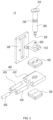
- Figure 1 is a perspective view of a local heating type 3D printer head according to the present disclosure
- Figure 2 is an exploded view of a local heating type 3D printer head according to the present disclosure
- Figure 3 is a perspective view of an internal configuration of a local heating type 3D printer head according to the present disclosure
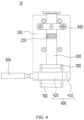
- Figure 4 is a front view of a local heating type 3D printer head according to the present disclosure
- Figure 5 is a cutaway view of a local heating type 3D printer head according to the present disclosure.
- a local heating type 3D printer head 1 may eject a printing composition while being moved by a drive device and a control device of a 3D printer.
- the multi-3D printer head 10 may include a head frame 100, a syringe 200 for ejecting a printing composition 211, a pressure supply part 300 to enable ejection of the printing composition 211, a heating part 400 to heat the syringe 200, and a temperature measurement part 500.
- Said head frame 100 may be formed in the form of a plate.
- the upper front face of the head frame 100 may be provided with a syringe fixing part 600 that allows the syringe 200 to be fixed.
- a recess 610 may be formed in the center of said syringe fixing part 600 into which the syringe 200 is inserted.
- the syringe 200 is secured to the head frame 100 with a syringe fixing part 600, and may include a receiving part 210 in which the printing composition 211 is received, and a nozzle part 220 through which the printing composition 211 received in the receiving part 210 is ejected.
- the printing composition 211 may include a thermoplastic polymer, in which the thermoplastic polymer is not particularly limited but is a polymer capable of having fluid-like flowability upon heating, for example it may include one or more selected from the group consisting of 3D printable materials, such as a lactide, caprolactone, glycolide, dioxanone, propylene, ethylene, vinylchloride, butadiene, methyl methacrylate, acrylic acid, 2-hydroxyethlymethacrylate, carbonate, and polyethylene terephthalate, ABS (acrylonitrile butadiene styrene), PCL (polycaprolactone), ASA (acrylonitrile-styrene-acrylate), SAN (Stryrene-Acrylonitrile copolymer), PS (Polystyrene), PPSF/PPSU (Polyphenylsulfone), Polyetherimide, PLA (Polylactic acid), PDL (Poly-d-lysine).
- 3D printable materials
- the syringe 200 may be provided with a heat sink part 230 that dissipates high heat to prevent the syringe 200 from overheating.
- the pressure supply part 300 is connected to the upper part of the syringe 200 and may supply pressure into the syringe 200 to eject the printing composition 211 through the nozzle part 220.
- the heating part 400 is provided on the outer peripheral surface of the lower part of the syringe 200 to locally heat the area around the nozzle part 220. Further, the heating part 400 may be provided with a heating block 410 provided on the outer peripheral surface of the lower part of the syringe 200, and may be provided with a cartridge heater 420 for heating by transferring heat to the heating block 410.
- the heating block 410 is provided by wrapping around the lower part of the syringe 200, and heats the printing composition 211 ejected into the nozzle part 220 to locally heat the periphery of the nozzle part 220 through which the printing composition 211 is ejected.
- the heating block 410 is preferably made of an aluminum material having excellent thermal conductivity.
- Said cartridge heaters 420 may be provided in plurality within the heating block 410.
- the cartridge heaters 420 are located at the same point on both sides of the syringe 200.
- the cartridge heaters 420 may be connected to an external thermostatic controller (not shown) for controlling the temperature of the syringe 200 and the heating block 410.
- Said temperature measurement part 500 may be provided at a side portion of the heating part 400 to measure the temperature of the syringe 200 or the heating block 410.
- the temperature measurement part 500 may include a temperature sensor and may be coupled to an external thermostatic controller (not shown) for controlling the temperature of the syringe 200 and the heating block 410.
- Said heating part adjustment plate 700 is removably disposed on top of the heating part 400 and covers the bottom of the syringe 200 and the heating part 400 to ensure a minimum heating area.
- the heating part adjustment plate 700 may be sized according to the heating area of the heating part 400.
- the heating part adjustment plate 700 may further be removably attached to the bottom of the heating part 400.
- the heating part adjustment plate 700 attached to the bottom of the heating part 400 is installed to wrap around the outer peripheral surface of the nozzle part 220.
- the syringe 200 and the nozzle part 220 may be wrapped and heated so that the printing composition 211 received in the syringe 200 may be ejected smoothly without solidification.
- the printing composition 211 received in the receiving part 210 of the syringe 200 may be ejected through the nozzle part 220 at the lower part of the syringe 200 to mold a predetermined three-dimensional biological structure.
- a heating part 400 is provided around the nozzle part 220 so that the area around the nozzle part 220 may be locally heated by heat generated by the heating block 410 and the cartridge heater 420.
- the heating part 400 is provided at the nozzle part 220 at the lower part of the syringe 200 to heat the area around the nozzle part 220 so that the printing composition 211 remains undeformed and intact with localized heating, allowing for smooth molding of the three-dimensional biological structure. Then, the area around the nozzle part 220 is heated by the heating part 400, and the printing composition 211 may be ejected through the nozzle part 220 by operation of the pressure supply part 300. Furthermore, the temperature of the syringe 200 and the heating block 410 may be measured in real time through the temperature measurement part 500 to maintain the heating temperature of the heating part 400 appropriately so that the printing composition 211 may be ejected smoothly.
- the heat generated by the heating part 400 may be transferred to the syringe 200 and the nozzle part 220 as much as possible without escaping to the outside, so that the printing composition 211 may be ejected smoothly without solidifying.
Landscapes
- Chemical & Material Sciences (AREA)
- Engineering & Computer Science (AREA)
- Materials Engineering (AREA)
- Manufacturing & Machinery (AREA)
- Physics & Mathematics (AREA)
- Mechanical Engineering (AREA)
- Optics & Photonics (AREA)
Abstract
Description
- The present disclosure relates to a local heating type three-dimensional (3D) printer head, and more particularly to a local heating type 3D printer head in which a region around a nozzle through which a printing composition is ejected may be locally heated and material deformation may be minimized and deterioration may be prevented or delayed.
- 3D printing technology refers to the technology of manufacturing three-dimensional structures by stacking printable material compositions in a predetermined pattern using a 3D printer and, in particular, the technology of three-dimensional printing biological tissue using biocompatible printing compositions is defined as 3D bioprinting.
- There is a lot of research being conducted using these 3D bioprinting systems to help heal diseases, such as organoids, organ-on-a-chip, and tissue and organ analogies for replacements of animal testing, and the like.
- Printing compositions used in 3D bioprinting are based on hydrogels, thermoplastic polymers, and the like, and may include cells or growth factors and the like.
- When these 3D bioprinting systems are used to manufacture three-dimensional structures such as organoids, organ-on-a-chip, and tissue and organ analogs for replacements of animal testing, multiple heads that may eject or print both biocompatible printing compositions such as hydrogels and thermoplastic polymer compositions are often used.
- In order to perform 3D printing using printing compositions based on hydrogels, thermoplastic polymers, and the like, the printing composition must be maintained in a flowable liquid phase so that it may be ejected within the 3D printer head.
- The printing composition comprising these thermoplastic polymers must be maintained at a high temperature inside the 3D printer head where it is ejected or printed so that it remains in a semi-solid state that is a flowable liquid phase inside the 3D printer head, where the temperature difference with the outside causes moisture contained in the outside air to condense on the surface of the 3D printer head or around the head, resulting in condensation.
- In addition, when printing thermoplastic synthetic polymer materials using 3D printing technology, the syringe containing the material is heated sufficiently to melt it before printing. When the material is heated for a long time, the high and continuous thermal energy causes the intermolecular bonds of the synthetic polymer material to break, resulting in changes in the material's properties (viscosity change, molecular weight reduction, and the like). These changes in properties may lead to defective products due to differences in the amount of material ejected and matters with smooth material ejection.
-
- (Patent reference 1):
Korean Patent Publication No. 10-1795559 - (Patent reference 2):
Korean Patent Publication No. 10-1975200 - Therefore, the present disclosure is designed to solve the above objectives, and the purpose is to provide a local heating type 3D printer head that may prevent deformation of the material by exposing the material to heat for a short period of time by locally heating around the ejection part of the material without heating the entire syringe.
- A local heating type 3D printer head according to an example embodiment of the present disclosure for achieving the above objectives may include: a head frame in the form of a plate; a syringe provided on said head frame to receive a printing composition and to eject the printing composition through a lower nozzle part; and a heating part provided on an outer peripheral surface of the lower part of the syringe to locally heat the area around the nozzle part.
- The top of the heating part may further include a heating part adjustment plate that covers the bottom of the syringe and the heating part to ensure a minimum heating area.
- The upper part of the heating part adjustment plate wraps around the outer peripheral surface of the heating part and the syringe.
- The bottom of said heating part may further include a heating part adjustment plate installed to wrap around an outer peripheral surface of the nozzle part to secure a minimum heating area.
- The thickness of the heating part adjustment plate may be formed to be less than or equal to the thickness of the heating part.
- An upper front face of said head frame may be provided with a syringe fixing part for fixing the syringe.
- The middle end of the syringe may be provided with a heat sink part that dissipates high heat to prevent the syringe from overheating.
- A thermoplastic polymer may be used in said printing composition.
- The heating part may include a heating block provided on an outer peripheral surface of the lower part of the syringe, and a plurality of cartridge heaters provided inside the heating block to transfer heat for heating.
- Said cartridge heaters may be located at the same point on either side of the syringe.
- The 3D printer head may further include a temperature measurement part installed at a side of the heating part to measure the temperature of the syringe.
- As described above, according to the local heating type 3D printer head according to the present disclosure, by providing a heating part at the lower part of the syringe where the printing composition is received, it is possible to locally heat the area around the nozzle part where the printing composition is ejected so that the material may be maintained in its original state without deformation, thereby maximizing the quality of the printed product.
-
-
Figure 1 is a perspective view of a local heating type 3D printer head according to the present disclosure. -
Figure 2 is an exploded view of a local heating type 3D printer head according to the present disclosure. -
Figure 3 is a perspective view of an internal configuration of a local heating type 3D printer head according to the present disclosure. -
Figure 4 is a front view of a local heating type 3D printer head according to the present disclosure. -
Figure 5 is a cutaway view of a local heating type 3D printer head according to the present disclosure. - The present disclosure is subject to various modifications and may have many example embodiments, certain of which are illustrated in the drawings and further described in the detailed description. However, this is not intended to limit the disclosure to any particular example embodiment and should be understood to include all modifications, equivalents, or substitutions that are within the spirit and scope of the disclosure.
- In the drawings, example embodiments of the disclosure are not limited to the particular forms shown and are exaggerated for clarity. Certain terms are used herein for the purpose of describing the disclosure and are not intended to limit the meaning or to limit the scope of the claims of the disclosure.
- As used herein, the phrase "and/or" is used to mean including at least one of the components listed before or after. In addition, the expression "connected to/combined with" is used to include being directly connected to another component or being indirectly connected through another component. In this specification, the singular includes the plural unless the context otherwise mentions. In addition, components, steps, operations, and elements referred to as "including" or "comprising" as used in the specification imply the presence or addition of one or more other components, steps, operations, and elements.
- In the description of the example embodiments, references to each layer, region, pattern, or structure being formed "on" or "under" the substrate, respective sides, regions, pads, or patterns include both being formed directly or by interposing other layers. The reference to "on"/"over" or "under"/"below" each layer is described with reference to the drawings.
- Hereinafter, example embodiments of the present disclosure will be described in detail with reference to the accompanying drawings.
-
Figure 1 is a perspective view of a local heating type 3D printer head according to the present disclosure;Figure 2 is an exploded view of a local heating type 3D printer head according to the present disclosure;Figure 3 is a perspective view of an internal configuration of a local heating type 3D printer head according to the present disclosure;Figure 4 is a front view of a local heating type 3D printer head according to the present disclosure; andFigure 5 is a cutaway view of a local heating type 3D printer head according to the present disclosure. - As shown in
FIGS. 1 to 5 , a local heating type 3D printer head 1 according to the present disclosure may eject a printing composition while being moved by a drive device and a control device of a 3D printer. Themulti-3D printer head 10 may include ahead frame 100, asyringe 200 for ejecting aprinting composition 211, apressure supply part 300 to enable ejection of theprinting composition 211, aheating part 400 to heat thesyringe 200, and atemperature measurement part 500. - Said
head frame 100 may be formed in the form of a plate. The upper front face of thehead frame 100 may be provided with asyringe fixing part 600 that allows thesyringe 200 to be fixed. In this case, arecess 610 may be formed in the center of saidsyringe fixing part 600 into which thesyringe 200 is inserted. Thesyringe 200 is secured to thehead frame 100 with asyringe fixing part 600, and may include a receivingpart 210 in which theprinting composition 211 is received, and anozzle part 220 through which theprinting composition 211 received in thereceiving part 210 is ejected. - The
printing composition 211 may include a thermoplastic polymer, in which the thermoplastic polymer is not particularly limited but is a polymer capable of having fluid-like flowability upon heating, for example it may include one or more selected from the group consisting of 3D printable materials, such as a lactide, caprolactone, glycolide, dioxanone, propylene, ethylene, vinylchloride, butadiene, methyl methacrylate, acrylic acid, 2-hydroxyethlymethacrylate, carbonate, and polyethylene terephthalate, ABS (acrylonitrile butadiene styrene), PCL (polycaprolactone), ASA (acrylonitrile-styrene-acrylate), SAN (Stryrene-Acrylonitrile copolymer), PS (Polystyrene), PPSF/PPSU (Polyphenylsulfone), Polyetherimide, PLA (Polylactic acid), PDL (Poly-d-lysine). - Anywhere other than the lower part of the
syringe 200, thesyringe 200 may be provided with aheat sink part 230 that dissipates high heat to prevent thesyringe 200 from overheating. - The
pressure supply part 300 is connected to the upper part of thesyringe 200 and may supply pressure into thesyringe 200 to eject theprinting composition 211 through thenozzle part 220. - The
heating part 400 is provided on the outer peripheral surface of the lower part of thesyringe 200 to locally heat the area around thenozzle part 220. Further, theheating part 400 may be provided with aheating block 410 provided on the outer peripheral surface of the lower part of thesyringe 200, and may be provided with acartridge heater 420 for heating by transferring heat to theheating block 410. - The
heating block 410 is provided by wrapping around the lower part of thesyringe 200, and heats theprinting composition 211 ejected into thenozzle part 220 to locally heat the periphery of thenozzle part 220 through which theprinting composition 211 is ejected. In this case, theheating block 410 is preferably made of an aluminum material having excellent thermal conductivity. - Said
cartridge heaters 420 may be provided in plurality within theheating block 410. Preferably, thecartridge heaters 420 are located at the same point on both sides of thesyringe 200. In this case, thecartridge heaters 420 may be connected to an external thermostatic controller (not shown) for controlling the temperature of thesyringe 200 and theheating block 410. - Said
temperature measurement part 500 may be provided at a side portion of theheating part 400 to measure the temperature of thesyringe 200 or theheating block 410. Thetemperature measurement part 500 may include a temperature sensor and may be coupled to an external thermostatic controller (not shown) for controlling the temperature of thesyringe 200 and theheating block 410. - Said heating
part adjustment plate 700 is removably disposed on top of theheating part 400 and covers the bottom of thesyringe 200 and theheating part 400 to ensure a minimum heating area. The heatingpart adjustment plate 700 may be sized according to the heating area of theheating part 400. - In addition, the heating
part adjustment plate 700 may further be removably attached to the bottom of theheating part 400. The heatingpart adjustment plate 700 attached to the bottom of theheating part 400 is installed to wrap around the outer peripheral surface of thenozzle part 220. In other words, by providing the heatingpart adjustment plate 700 at the top or bottom of theheating part 400, thesyringe 200 and thenozzle part 220 may be wrapped and heated so that theprinting composition 211 received in thesyringe 200 may be ejected smoothly without solidification. - Meanwhile, the thickness of the heating
part adjustment plate 700 may be formed to be the same or smaller than theheating part 400. - The working state of the local heating type 3D printer head of the present disclosure including the above structure is as follows.
- The
printing composition 211 received in the receivingpart 210 of thesyringe 200 may be ejected through thenozzle part 220 at the lower part of thesyringe 200 to mold a predetermined three-dimensional biological structure. At this time, when theprinting composition 211 is ejected through thenozzle part 220, aheating part 400 is provided around thenozzle part 220 so that the area around thenozzle part 220 may be locally heated by heat generated by theheating block 410 and thecartridge heater 420. - As such, the
heating part 400 is provided at thenozzle part 220 at the lower part of thesyringe 200 to heat the area around thenozzle part 220 so that theprinting composition 211 remains undeformed and intact with localized heating, allowing for smooth molding of the three-dimensional biological structure. Then, the area around thenozzle part 220 is heated by theheating part 400, and theprinting composition 211 may be ejected through thenozzle part 220 by operation of thepressure supply part 300. Furthermore, the temperature of thesyringe 200 and theheating block 410 may be measured in real time through thetemperature measurement part 500 to maintain the heating temperature of theheating part 400 appropriately so that theprinting composition 211 may be ejected smoothly. - In addition, by removably providing the heating
part adjustment plate 700 while wrapping around the outside of theheating part 400, the heat generated by theheating part 400 may be transferred to thesyringe 200 and thenozzle part 220 as much as possible without escaping to the outside, so that theprinting composition 211 may be ejected smoothly without solidifying. - In the above detailed description of the disclosure, only particular example embodiments thereof have been described. However, the disclosure should not be understood to be limited to the special forms mentioned in the detailed description, but rather to include all variations, equivalents and substitutes within the spirit and scope of the disclosure as defined by the appended claims.
- In other words, the disclosure is not limited to the specific example embodiments and descriptions set forth above, and various modifications may be made by one having ordinary skill in the art to which the disclosure belongs without departing from the spirit of the disclosure as claimed, and such modifications will fall within the scope of protection of the disclosure.
-
- 10:
- 3D printer head
- 100:
- Head frame
- 200:
- Syringe
- 210:
- Receiving part
- 211:
- Printing composition
- 220:
- Nozzle part
- 230:
- Heat sink part
- 300:
- Pressure supply part
- 400:
- Heating part
- 410:
- Heating block
- 420:
- Cartridge heater
- 500:
- Temperature measurement part
- 600:
- Syringe fixing part
- 610:
- Recess
- 700:
- Heating part adjustment plate
Claims (11)
- A local heating type three-dimensional (3D) printer head, the local heating type 3D printer comprises:a head frame;a syringe provided on the head frame to receive a printing composition and to eject the printing composition through a lower nozzle part; anda heating part provided on an outer peripheral surface of the lower part of the syringe to locally heat the area around the nozzle part.
- The local heating type 3D printer head of claim 1, wherein the top of the heating part further comprises a heating part adjustment plate that covers a bottom of the syringe and the heating part to ensure a minimum heating area.
- The local heating type 3D printer head of claim 2, wherein the upper part of the heating part adjustment plate wraps around the outer peripheral surface of the syringe and the heating part.
- The local heating type 3D printer head of claim 1, wherein the bottom of the heating part further comprises a heating part adjustment plate installed to wrap around an outer peripheral surface of a nozzle part to secure a minimum heating area.
- The local heating type 3D printer head of claim 2, wherein the thickness of the heating part adjustment plate is formed to be less than or equal to the thickness of the heating part.
- The local heating type 3D printer head of claim 1, wherein an upper front face of the head frame is provided with a syringe fixing part for fixing the syringe.
- The local heating type 3D printer head of claim 1, wherein the middle end of the syringe is provided with a heat sink part that dissipates high heat to prevent the syringe from overheating.
- The local heating type 3D printer head of claim 1, wherein a thermoplastic polymer is used in the printing composition.
- The local heating type 3D printer head of claim 1, wherein the heating part comprises:a heating block provided on an outer peripheral surface of the lower part of the syringe; anda plurality of cartridge heaters provided inside the heating block to transfer heat for heating the syringe.
- The local heating type 3D printer head of claim 9, wherein the cartridge heaters are located at the same point on either side of the syringe.
- The local heating type 3D printer head of claim 1, further comprises a temperature measurement part installed at a side of the heating part to measure the temperature of the syringe.
Applications Claiming Priority (2)
| Application Number | Priority Date | Filing Date | Title |
|---|---|---|---|
| KR1020220150062A KR102737953B1 (en) | 2022-11-11 | 2022-11-11 | 3d printer head with local heating method |
| PCT/KR2022/020314 WO2024101526A1 (en) | 2022-11-11 | 2022-12-14 | 3d printer head using local heating method |
Publications (4)
| Publication Number | Publication Date |
|---|---|
| EP4393681A1 true EP4393681A1 (en) | 2024-07-03 |
| EP4393681A4 EP4393681A4 (en) | 2025-03-05 |
| EP4393681C0 EP4393681C0 (en) | 2026-02-04 |
| EP4393681B1 EP4393681B1 (en) | 2026-02-04 |
Family
ID=91033074
Family Applications (1)
| Application Number | Title | Priority Date | Filing Date |
|---|---|---|---|
| EP22940502.2A Active EP4393681B1 (en) | 2022-11-11 | 2022-12-14 | 3d printer head using local heating method |
Country Status (6)
| Country | Link |
|---|---|
| US (1) | US20250100221A1 (en) |
| EP (1) | EP4393681B1 (en) |
| JP (1) | JP7730191B2 (en) |
| KR (1) | KR102737953B1 (en) |
| CN (1) | CN118339009A (en) |
| WO (1) | WO2024101526A1 (en) |
Families Citing this family (1)
| Publication number | Priority date | Publication date | Assignee | Title |
|---|---|---|---|---|
| US20250033281A1 (en) * | 2023-07-25 | 2025-01-30 | Anthony Homen | Dual heater cartridge heater block and methods thereof |
Family Cites Families (22)
| Publication number | Priority date | Publication date | Assignee | Title |
|---|---|---|---|---|
| US10441689B2 (en) * | 2014-08-10 | 2019-10-15 | Louisiana Tech Research Corporation | Methods and devices for three-dimensional printing or additive manufacturing of bioactive medical devices |
| KR101772563B1 (en) * | 2015-11-30 | 2017-08-30 | 주식회사 포머스팜 | Heating nozzle structure for 3D printer |
| KR101795559B1 (en) | 2016-01-07 | 2017-11-08 | 주식회사 티앤알바이오팹 | Cell Printing Device for Heat-sensitive Cell-printing Composition |
| KR101975200B1 (en) | 2016-06-02 | 2019-05-07 | 주식회사 티앤알바이오팹 | 3D Printing Apparatus of Bio-Ink |
| CN205853382U (en) * | 2016-08-12 | 2017-01-04 | 渭南高新区火炬科技发展有限责任公司 | A kind of 3D printer plunger type extruder structure |
| US10807292B2 (en) * | 2016-10-24 | 2020-10-20 | The Regents Of The University Of Michigan | Extrusion die and nozzle cooling system for large scale 3D additive manufacturing |
| CN206394017U (en) * | 2016-12-16 | 2017-08-11 | 中国地质大学(武汉) | A kind of printer of injecting type 3D printing head and application 3D printing head |
| US10875244B2 (en) * | 2017-05-17 | 2020-12-29 | Slice Engineering LLC | Adaptable high-performance extrusion head for fused filament fabrication systems |
| CN208228287U (en) * | 2017-11-29 | 2018-12-14 | 哈尔滨拓思科技有限公司 | A kind of thermoplastic food 3D printer extrusion system |
| KR20190063819A (en) * | 2017-11-30 | 2019-06-10 | 최성덕 | Nozzle unit of 3d printer |
| CN107932898A (en) * | 2017-12-22 | 2018-04-20 | 青岛理工大学 | Electric field driven fused jet deposition 3D printer and working method thereof |
| CN209346074U (en) * | 2018-05-11 | 2019-09-06 | 上海工程技术大学 | A kind of Intelligent hot electric heating spray head of food 3D printer |
| CN110605852A (en) * | 2018-06-14 | 2019-12-24 | 麦递途医疗科技(上海)有限公司 | A nozzle with zone-accurate heating |
| KR102165179B1 (en) * | 2018-12-12 | 2020-10-14 | 한성대학교 산학협력단 | Cooling system of 3d printer being capable of printing soft materials |
| KR20200080407A (en) * | 2018-12-19 | 2020-07-07 | 동명대학교산학협력단 | A Device with a dual heating nozzle for a high speed deposition |
| CN110154389A (en) * | 2019-04-26 | 2019-08-23 | 长兴时印科技有限公司 | A kind of western-style restaurant's 3D printing equipment |
| CN211091838U (en) * | 2019-09-30 | 2020-07-28 | 南京威布三维科技有限公司 | Internal heating formula food 3D prints crowded material device |
| CN110561740A (en) * | 2019-10-12 | 2019-12-13 | 四川大学 | Quick forming feeding device |
| EP4000867A1 (en) * | 2020-11-12 | 2022-05-25 | Laser Engineering & Development Ltd. | Printer nozzle structure |
| EP4015195A1 (en) * | 2020-12-18 | 2022-06-22 | Bond High Performance 3D Technology B.V. | Extrusion-based additive manufacturing: 3d printing system and method |
| CN216885219U (en) * | 2021-07-30 | 2022-07-05 | 深圳市创想三帝科技有限公司 | A nozzle module of a 3D printer and a 3D printer |
| US11931958B2 (en) * | 2022-06-29 | 2024-03-19 | Prisam Llc | Extrusion nozzle for additive manufacturing |
-
2022
- 2022-11-11 KR KR1020220150062A patent/KR102737953B1/en active Active
- 2022-12-14 US US18/558,509 patent/US20250100221A1/en active Pending
- 2022-12-14 EP EP22940502.2A patent/EP4393681B1/en active Active
- 2022-12-14 WO PCT/KR2022/020314 patent/WO2024101526A1/en not_active Ceased
- 2022-12-14 CN CN202280036107.4A patent/CN118339009A/en active Pending
- 2022-12-14 JP JP2023568256A patent/JP7730191B2/en active Active
Also Published As
| Publication number | Publication date |
|---|---|
| WO2024101526A1 (en) | 2024-05-16 |
| US20250100221A1 (en) | 2025-03-27 |
| KR20240068974A (en) | 2024-05-20 |
| EP4393681A4 (en) | 2025-03-05 |
| JP7730191B2 (en) | 2025-08-27 |
| JP2024544097A (en) | 2024-11-28 |
| EP4393681C0 (en) | 2026-02-04 |
| EP4393681B1 (en) | 2026-02-04 |
| KR102737953B1 (en) | 2024-12-05 |
| CN118339009A (en) | 2024-07-12 |
Similar Documents
| Publication | Publication Date | Title |
|---|---|---|
| US20250100221A1 (en) | Local heating type three-dimensional (3d) printer head | |
| US7014810B2 (en) | Method of producing solid shape forms containing an active ingredient | |
| JP5419756B2 (en) | Temperature sensor calibration method, recording head manufacturing method, and ink jet recording apparatus | |
| CN101489792B (en) | Printing on heated substrates | |
| EP1590149B1 (en) | Process of and apparatus for three-dimensional printing | |
| JP6466585B2 (en) | Creating 3D objects | |
| EP2488347B1 (en) | Three-dimensional printer and method for creating a three-dimensional model | |
| US8216505B2 (en) | Method for manufacturing solid ink sticks with an injection molding process | |
| JP2017206011A (en) | Improved interlayer adhesion in part printed by additive manufacturing | |
| JPH02500583A (en) | Platen structure for fused inkjet equipment | |
| US20160009028A1 (en) | Three-dimensional printer | |
| DK3037235T3 (en) | Device and method for delivering plastic material to a mold cavity | |
| JP2013166026A (en) | Mold for actuation sled | |
| JP7864260B2 (en) | Dosage packaging and method of manufacturing the same | |
| JP2023101811A5 (en) | ||
| US20160356552A1 (en) | Molded plastic objects having an integrated heat spreader and methods of manufacture of same | |
| US8900657B2 (en) | Transferring medium manufacturing method and transferring medium | |
| JP2006150961A (en) | Method of handling image receiving sheet, and heat melting inkjet printer adopting the method | |
| JP2021107123A (en) | Inkjet recording device and fixing control method | |
| JP2021107123A5 (en) | ||
| JP2010089504A (en) | System and method for cutting of media having phase change ink image | |
| TW200804056A (en) | Cooling mechanism of injection molding machine for disk | |
| US20120256994A1 (en) | Inkjet recording device | |
| JP3659071B2 (en) | Injection molding method for picture-molded products | |
| JPS6321399Y2 (en) |
Legal Events
| Date | Code | Title | Description |
|---|---|---|---|
| STAA | Information on the status of an ep patent application or granted ep patent |
Free format text: STATUS: UNKNOWN |
|
| STAA | Information on the status of an ep patent application or granted ep patent |
Free format text: STATUS: THE INTERNATIONAL PUBLICATION HAS BEEN MADE |
|
| PUAI | Public reference made under article 153(3) epc to a published international application that has entered the european phase |
Free format text: ORIGINAL CODE: 0009012 |
|
| STAA | Information on the status of an ep patent application or granted ep patent |
Free format text: STATUS: REQUEST FOR EXAMINATION WAS MADE |
|
| 17P | Request for examination filed |
Effective date: 20231108 |
|
| AK | Designated contracting states |
Kind code of ref document: A1 Designated state(s): AL AT BE BG CH CY CZ DE DK EE ES FI FR GB GR HR HU IE IS IT LI LT LU LV MC ME MK MT NL NO PL PT RO RS SE SI SK SM TR |
|
| A4 | Supplementary search report drawn up and despatched |
Effective date: 20250203 |
|
| RIC1 | Information provided on ipc code assigned before grant |
Ipc: B29C 64/106 20170101ALN20250128BHEP Ipc: B33Y 10/00 20150101ALI20250128BHEP Ipc: B33Y 70/00 20200101ALI20250128BHEP Ipc: B33Y 30/00 20150101ALI20250128BHEP Ipc: B29C 64/295 20170101ALI20250128BHEP Ipc: B29C 64/118 20170101ALI20250128BHEP Ipc: B29C 64/209 20170101AFI20250128BHEP |
|
| GRAP | Despatch of communication of intention to grant a patent |
Free format text: ORIGINAL CODE: EPIDOSNIGR1 |
|
| STAA | Information on the status of an ep patent application or granted ep patent |
Free format text: STATUS: GRANT OF PATENT IS INTENDED |
|
| RIC1 | Information provided on ipc code assigned before grant |
Ipc: B29C 64/209 20170101AFI20251002BHEP Ipc: B29C 64/118 20170101ALI20251002BHEP Ipc: B29C 64/295 20170101ALI20251002BHEP Ipc: B33Y 30/00 20150101ALI20251002BHEP Ipc: B33Y 70/00 20200101ALI20251002BHEP Ipc: B33Y 10/00 20150101ALI20251002BHEP Ipc: B29C 64/106 20170101ALN20251002BHEP |
|
| GRAS | Grant fee paid |
Free format text: ORIGINAL CODE: EPIDOSNIGR3 |
|
| DAV | Request for validation of the european patent (deleted) | ||
| DAX | Request for extension of the european patent (deleted) | ||
| INTG | Intention to grant announced |
Effective date: 20251022 |
|
| GRAA | (expected) grant |
Free format text: ORIGINAL CODE: 0009210 |
|
| STAA | Information on the status of an ep patent application or granted ep patent |
Free format text: STATUS: THE PATENT HAS BEEN GRANTED |
|
| AK | Designated contracting states |
Kind code of ref document: B1 Designated state(s): AL AT BE BG CH CY CZ DE DK EE ES FI FR GB GR HR HU IE IS IT LI LT LU LV MC ME MK MT NL NO PL PT RO RS SE SI SK SM TR |
|
| REG | Reference to a national code |
Ref country code: CH Ref legal event code: F10 Free format text: ST27 STATUS EVENT CODE: U-0-0-F10-F00 (AS PROVIDED BY THE NATIONAL OFFICE) Effective date: 20260204 Ref country code: GB Ref legal event code: FG4D |
|
| REG | Reference to a national code |
Ref country code: IE Ref legal event code: FG4D |
|
| U01 | Request for unitary effect filed |
Effective date: 20260204 |
|
| U07 | Unitary effect registered |
Designated state(s): AT BE BG DE DK EE FI FR IT LT LU LV MT NL PT RO SE SI Effective date: 20260210 |
|
| PG25 | Lapsed in a contracting state [announced via postgrant information from national office to epo] |
Ref country code: RS Free format text: LAPSE BECAUSE OF FAILURE TO SUBMIT A TRANSLATION OF THE DESCRIPTION OR TO PAY THE FEE WITHIN THE PRESCRIBED TIME-LIMIT Effective date: 20260504 |
|
| PG25 | Lapsed in a contracting state [announced via postgrant information from national office to epo] |
Ref country code: ES Free format text: LAPSE BECAUSE OF FAILURE TO SUBMIT A TRANSLATION OF THE DESCRIPTION OR TO PAY THE FEE WITHIN THE PRESCRIBED TIME-LIMIT Effective date: 20260204 |
|
| PG25 | Lapsed in a contracting state [announced via postgrant information from national office to epo] |
Ref country code: PL Free format text: LAPSE BECAUSE OF FAILURE TO SUBMIT A TRANSLATION OF THE DESCRIPTION OR TO PAY THE FEE WITHIN THE PRESCRIBED TIME-LIMIT Effective date: 20260204 |
|
| PG25 | Lapsed in a contracting state [announced via postgrant information from national office to epo] |
Ref country code: GR Free format text: LAPSE BECAUSE OF FAILURE TO SUBMIT A TRANSLATION OF THE DESCRIPTION OR TO PAY THE FEE WITHIN THE PRESCRIBED TIME-LIMIT Effective date: 20260505 |
|
| PG25 | Lapsed in a contracting state [announced via postgrant information from national office to epo] |
Ref country code: NO Free format text: LAPSE BECAUSE OF FAILURE TO SUBMIT A TRANSLATION OF THE DESCRIPTION OR TO PAY THE FEE WITHIN THE PRESCRIBED TIME-LIMIT Effective date: 20260504 |
|
| PG25 | Lapsed in a contracting state [announced via postgrant information from national office to epo] |
Ref country code: HR Free format text: LAPSE BECAUSE OF FAILURE TO SUBMIT A TRANSLATION OF THE DESCRIPTION OR TO PAY THE FEE WITHIN THE PRESCRIBED TIME-LIMIT Effective date: 20260204 |
|
| PG25 | Lapsed in a contracting state [announced via postgrant information from national office to epo] |
Ref country code: IS Free format text: LAPSE BECAUSE OF FAILURE TO SUBMIT A TRANSLATION OF THE DESCRIPTION OR TO PAY THE FEE WITHIN THE PRESCRIBED TIME-LIMIT Effective date: 20260604 |