EP4393673A1 - Filter for introducing physical foaming agent, manufacturing device and manufacturing method for foam molded product - Google Patents
Filter for introducing physical foaming agent, manufacturing device and manufacturing method for foam molded product Download PDFInfo
- Publication number
- EP4393673A1 EP4393673A1 EP22860908.7A EP22860908A EP4393673A1 EP 4393673 A1 EP4393673 A1 EP 4393673A1 EP 22860908 A EP22860908 A EP 22860908A EP 4393673 A1 EP4393673 A1 EP 4393673A1
- Authority
- EP
- European Patent Office
- Prior art keywords
- foaming agent
- physical foaming
- introduction
- molten resin
- resin
- Prior art date
- Legal status (The legal status is an assumption and is not a legal conclusion. Google has not performed a legal analysis and makes no representation as to the accuracy of the status listed.)
- Pending
Links
Images




Classifications
-
- B—PERFORMING OPERATIONS; TRANSPORTING
- B29—WORKING OF PLASTICS; WORKING OF SUBSTANCES IN A PLASTIC STATE IN GENERAL
- B29C—SHAPING OR JOINING OF PLASTICS; SHAPING OF MATERIAL IN A PLASTIC STATE, NOT OTHERWISE PROVIDED FOR; AFTER-TREATMENT OF THE SHAPED PRODUCTS, e.g. REPAIRING
- B29C44/00—Shaping by internal pressure generated in the material, e.g. swelling or foaming ; Producing porous or cellular expanded plastics articles
- B29C44/34—Auxiliary operations
- B29C44/36—Feeding the material to be shaped
- B29C44/38—Feeding the material to be shaped into a closed space, i.e. to make articles of definite length
- B29C44/42—Feeding the material to be shaped into a closed space, i.e. to make articles of definite length using pressure difference, e.g. by injection or by vacuum
- B29C44/424—Details of machines
-
- B—PERFORMING OPERATIONS; TRANSPORTING
- B29—WORKING OF PLASTICS; WORKING OF SUBSTANCES IN A PLASTIC STATE IN GENERAL
- B29C—SHAPING OR JOINING OF PLASTICS; SHAPING OF MATERIAL IN A PLASTIC STATE, NOT OTHERWISE PROVIDED FOR; AFTER-TREATMENT OF THE SHAPED PRODUCTS, e.g. REPAIRING
- B29C44/00—Shaping by internal pressure generated in the material, e.g. swelling or foaming ; Producing porous or cellular expanded plastics articles
- B29C44/02—Shaping by internal pressure generated in the material, e.g. swelling or foaming ; Producing porous or cellular expanded plastics articles for articles of definite length, i.e. discrete articles
-
- B—PERFORMING OPERATIONS; TRANSPORTING
- B29—WORKING OF PLASTICS; WORKING OF SUBSTANCES IN A PLASTIC STATE IN GENERAL
- B29C—SHAPING OR JOINING OF PLASTICS; SHAPING OF MATERIAL IN A PLASTIC STATE, NOT OTHERWISE PROVIDED FOR; AFTER-TREATMENT OF THE SHAPED PRODUCTS, e.g. REPAIRING
- B29C44/00—Shaping by internal pressure generated in the material, e.g. swelling or foaming ; Producing porous or cellular expanded plastics articles
- B29C44/34—Auxiliary operations
- B29C44/3442—Mixing, kneading or conveying the foamable material
- B29C44/3446—Feeding the blowing agent
-
- B—PERFORMING OPERATIONS; TRANSPORTING
- B29—WORKING OF PLASTICS; WORKING OF SUBSTANCES IN A PLASTIC STATE IN GENERAL
- B29C—SHAPING OR JOINING OF PLASTICS; SHAPING OF MATERIAL IN A PLASTIC STATE, NOT OTHERWISE PROVIDED FOR; AFTER-TREATMENT OF THE SHAPED PRODUCTS, e.g. REPAIRING
- B29C44/00—Shaping by internal pressure generated in the material, e.g. swelling or foaming ; Producing porous or cellular expanded plastics articles
- B29C44/34—Auxiliary operations
- B29C44/36—Feeding the material to be shaped
-
- B—PERFORMING OPERATIONS; TRANSPORTING
- B29—WORKING OF PLASTICS; WORKING OF SUBSTANCES IN A PLASTIC STATE IN GENERAL
- B29C—SHAPING OR JOINING OF PLASTICS; SHAPING OF MATERIAL IN A PLASTIC STATE, NOT OTHERWISE PROVIDED FOR; AFTER-TREATMENT OF THE SHAPED PRODUCTS, e.g. REPAIRING
- B29C44/00—Shaping by internal pressure generated in the material, e.g. swelling or foaming ; Producing porous or cellular expanded plastics articles
- B29C44/34—Auxiliary operations
- B29C44/36—Feeding the material to be shaped
- B29C44/38—Feeding the material to be shaped into a closed space, i.e. to make articles of definite length
- B29C44/42—Feeding the material to be shaped into a closed space, i.e. to make articles of definite length using pressure difference, e.g. by injection or by vacuum
-
- B—PERFORMING OPERATIONS; TRANSPORTING
- B29—WORKING OF PLASTICS; WORKING OF SUBSTANCES IN A PLASTIC STATE IN GENERAL
- B29C—SHAPING OR JOINING OF PLASTICS; SHAPING OF MATERIAL IN A PLASTIC STATE, NOT OTHERWISE PROVIDED FOR; AFTER-TREATMENT OF THE SHAPED PRODUCTS, e.g. REPAIRING
- B29C44/00—Shaping by internal pressure generated in the material, e.g. swelling or foaming ; Producing porous or cellular expanded plastics articles
- B29C44/34—Auxiliary operations
- B29C44/36—Feeding the material to be shaped
- B29C44/38—Feeding the material to be shaped into a closed space, i.e. to make articles of definite length
- B29C44/42—Feeding the material to be shaped into a closed space, i.e. to make articles of definite length using pressure difference, e.g. by injection or by vacuum
- B29C44/422—Feeding the material to be shaped into a closed space, i.e. to make articles of definite length using pressure difference, e.g. by injection or by vacuum by injecting by forward movement of the plastizising screw
-
- B—PERFORMING OPERATIONS; TRANSPORTING
- B29—WORKING OF PLASTICS; WORKING OF SUBSTANCES IN A PLASTIC STATE IN GENERAL
- B29C—SHAPING OR JOINING OF PLASTICS; SHAPING OF MATERIAL IN A PLASTIC STATE, NOT OTHERWISE PROVIDED FOR; AFTER-TREATMENT OF THE SHAPED PRODUCTS, e.g. REPAIRING
- B29C44/00—Shaping by internal pressure generated in the material, e.g. swelling or foaming ; Producing porous or cellular expanded plastics articles
- B29C44/34—Auxiliary operations
- B29C44/60—Measuring, controlling or regulating
-
- B—PERFORMING OPERATIONS; TRANSPORTING
- B29—WORKING OF PLASTICS; WORKING OF SUBSTANCES IN A PLASTIC STATE IN GENERAL
- B29C—SHAPING OR JOINING OF PLASTICS; SHAPING OF MATERIAL IN A PLASTIC STATE, NOT OTHERWISE PROVIDED FOR; AFTER-TREATMENT OF THE SHAPED PRODUCTS, e.g. REPAIRING
- B29C45/00—Injection moulding, i.e. forcing the required volume of moulding material through a nozzle into a closed mould; Apparatus therefor
- B29C45/17—Component parts, details or accessories; Auxiliary operations
- B29C45/1703—Introducing an auxiliary fluid into the mould
- B29C45/1704—Introducing an auxiliary fluid into the mould the fluid being introduced into the interior of the injected material which is still in a molten state, e.g. for producing hollow articles
- B29C2045/1722—Introducing an auxiliary fluid into the mould the fluid being introduced into the interior of the injected material which is still in a molten state, e.g. for producing hollow articles injecting fluids containing plastic material
-
- B—PERFORMING OPERATIONS; TRANSPORTING
- B29—WORKING OF PLASTICS; WORKING OF SUBSTANCES IN A PLASTIC STATE IN GENERAL
- B29C—SHAPING OR JOINING OF PLASTICS; SHAPING OF MATERIAL IN A PLASTIC STATE, NOT OTHERWISE PROVIDED FOR; AFTER-TREATMENT OF THE SHAPED PRODUCTS, e.g. REPAIRING
- B29C45/00—Injection moulding, i.e. forcing the required volume of moulding material through a nozzle into a closed mould; Apparatus therefor
- B29C45/17—Component parts, details or accessories; Auxiliary operations
- B29C45/1703—Introducing an auxiliary fluid into the mould
- B29C45/1704—Introducing an auxiliary fluid into the mould the fluid being introduced into the interior of the injected material which is still in a molten state, e.g. for producing hollow articles
-
- B—PERFORMING OPERATIONS; TRANSPORTING
- B29—WORKING OF PLASTICS; WORKING OF SUBSTANCES IN A PLASTIC STATE IN GENERAL
- B29K—INDEXING SCHEME ASSOCIATED WITH SUBCLASSES B29B, B29C OR B29D, RELATING TO MOULDING MATERIALS OR TO MATERIALS FOR MOULDS, REINFORCEMENTS, FILLERS OR PREFORMED PARTS, e.g. INSERTS
- B29K2101/00—Use of unspecified macromolecular compounds as moulding material
- B29K2101/12—Thermoplastic materials
-
- B—PERFORMING OPERATIONS; TRANSPORTING
- B29—WORKING OF PLASTICS; WORKING OF SUBSTANCES IN A PLASTIC STATE IN GENERAL
- B29K—INDEXING SCHEME ASSOCIATED WITH SUBCLASSES B29B, B29C OR B29D, RELATING TO MOULDING MATERIALS OR TO MATERIALS FOR MOULDS, REINFORCEMENTS, FILLERS OR PREFORMED PARTS, e.g. INSERTS
- B29K2105/00—Condition, form or state of moulded material or of the material to be shaped
- B29K2105/04—Condition, form or state of moulded material or of the material to be shaped cellular or porous
Definitions
- the present invention relates to a physical foaming agent introduction filter, and an apparatus and a method for producing a foamed molded product.
- Patent Literature 1 discloses a method for molding a foamed molded product, using relatively low-pressure nitrogen, carbon dioxide, or the like without requiring a supercritical fluid. According to this method, without using a special high-pressure apparatus, fine foam cells can be formed in a molded product by a simple process with a low-pressure physical foaming agent.
- the method includes: plasticizing and melting the thermoplastic resin to form the molten resin, in the plasticization zone; supplying a pressurized fluid including the physical foaming agent at a fixed pressure to the introduction speed adjustment container, and introducing the pressurized fluid at the fixed pressure from the introduction speed adjustment container into the starvation zone, to maintain the starvation zone at the fixed pressure; bringing the molten resin into a starved state, in the starvation zone; bringing, while maintaining the starvation zone at the fixed pressure, the molten resin in the starved state into contact with the pressurized fluid, in the starvation zone; and molding the molten resin brought into contact with the pressurized fluid including the physical foaming agent into a foamed molded product.
- Patent Literature 1 JP 6777553 B2
- the thicknesses of the separation walls between the physical foaming agent introduction holes longitudinally and laterally adjacent to each other are defined as 0.01 to 1.0 mm, because, when the thicknesses of the separation walls are thinner than 0.01 mm, the thicknesses of the separation walls become excessively thin to cause the strength of the physical foaming agent introduction filter to decrease, and because, when the thicknesses of the separation walls exceed 1.0 mm, the thicknesses of the separation walls become excessively thick and the number of physical foaming agent introduction holes is reduced.
- the introduction port 202 is provided as an opening for introducing a physical foaming agent into the starvation zone 23.
- the introduction speed adjustment container 300 is connected to the introduction port 202.
- the bomb 100 is connected to the introduction speed adjustment container 300 by piping 154 via a pressure reducing valve 151, a pressure gauge 152, and an open valve 153.
- the bomb 100 is configured to supply a physical foaming agent into the cylinder 210 via the introduction speed adjustment container 300.
- a physical foaming agent at a fixed pressure is supplied to the introduction speed adjustment container 300, and then the pressurized fluid at the fixed pressure is introduced from the introduction speed adjustment container 300 into the starvation zone 23, whereby the pressure in the starvation zone 23 is maintained at the fixed pressure (step S2 in Fig. 3 ).
- the pressure of the physical foaming agent introduced into the starvation zone 23 is fixed, and the pressure in the starvation zone 23 is maintained at a fixed pressure equal to the pressure of the introduced physical foaming agent.
- the pressure of the physical foaming agent is preferably 0.5 MPa to 30 MPa, more preferably 1 MPa to 25 MPa, and still more preferably 1 MPa to 15 MPa.
- the wording the pressure of the physical foaming agent for pressurizing molten resin is "fixed” means that the fluctuation range of a pressure with respect to a predetermined pressure is preferably within ⁇ 20%, and more preferably within ⁇ 10%.
- the pressure in the starvation zone 23 is measured, for example, by a pressure sensor 27 provided at a position facing the introduction port 202 of the plasticizing cylinder 210.
- the starvation zone 23 moves inside the plasticizing cylinder 210 in a forward-backward direction along with forward and backward movement of the screw 20.
- the pressure sensor 27 illustrated in Fig. 1 is always provided at a position allowing the pressure sensor 27 to exist in the starvation zone 23, within the range form the most forward position to the most backward position of the starvation zone 23.
- the position facing the introduction port 202 is also always within the starvation zone 23.
- the pressure sensor 27 is not provided at the position facing the introduction port 202, but the pressure indicated by the pressure sensor 27 and the pressure at the position facing the introduction port 202 are substantially equal.
- the physical foaming agent is supplied from the bomb 100 to the starvation zone 23, through the introduction port 202 via the introduction speed adjustment container 300.
- the physical foaming agent is subjected to reduction in pressure to a predetermined pressure using the pressure reducing valve 151, and is then introduced through the introduction port 202 into the starvation zone 23 without passing through a pressure increase apparatus or the like.
- control is not performed for the amount of introduction, the time of introduction, and the like of the physical foaming agent introduced into the plasticizing cylinder 210.
- a section from the pressure reducing valve 151 through the introduction speed adjustment container 300 to the starvation zone 23 in the plasticizing cylinder 210 is maintained at the fixed pressure of the physical foaming agent.
- the introduction port 202 for the physical foaming agent has an inner diameter D1 larger than that of an introduction port for a physical foaming agent in a conventional production apparatus.
- the introduction port 202 has such a larger inner diameter D1, and thus is free from being completely clogged, thereby allowing the introduction port 202 to function as an introduction port.
- the inner diameter of the plasticizing cylinder 210 becomes larger, that is, as the outer diameter of the plasticizing cylinder 210 becomes larger, it is possible to easily cause the inner diameter D1 of the introduction port 202 to be larger.
- the inner diameter D1 of the introduction port 202 means the inner diameter of an opening on an inner wall 210a of the plasticizing cylinder 210.
- the shape of the introduction port 202 that is, the shape of the opening on the inner wall 210a of the plasticizing cylinder 210 is not limited to a perfect circle, and may also be an ellipse or a polygon. In a case where the shape of the introduction port 202 is an ellipse or a polygon, a diameter of a perfect circle having an area equal to the area of the introduction port 202 is defined as the "inner diameter D1 of the introduction port 202".
- the introduction speed adjustment container 300 has a function of setting the pressure of the physical foaming agent and the pressure in the starvation zone 23 in the plasticizing cylinder 210 to the same fixed pressure, and maintaining the pressure in the starvation zone 23 at the fixed pressure. For example, if a large amount of the physical foaming agent is consumed in the starvation zone 23, there may be a case in which the supply of the physical foaming agent cannot catch up with the consumption to rapidly decrease the pressure in the starvation zone 23. However, with the introduction speed adjustment container 300, the physical foaming agent can be stably supplied, thereby reducing the fluctuation in pressure in the starvation zone 23.
- the introduction speed adjustment container 300 is formed to have a certain volume or more, whereby the flow velocity of the physical foaming agent to be introduced into the plasticizing cylinder 210 is made gentle and a time during which the physical foaming agent stays inside the introduction speed adjustment container 300 is secured.
- the introduction speed adjustment container 300 is directly connected to the plasticizing cylinder 210 heated by the band heater (not illustrated) disposed in the periphery of the plasticizing cylinder 210, and heat on the plasticizing cylinder 210 is also conducted to the introduction speed adjustment container 300.
- the physical foaming agent inside the introduction speed adjustment container 300 is heated, which reduces a temperature difference between the physical foaming agent and the molten resin to prevent the temperature of the molten resin, with which the physical foaming agent comes into contact, from being extremely lowered, thereby stabilizing the amount of dissolution (amount of permeation) of the physical foaming agent in the molten resin. That is, the introduction speed adjustment container 300 functions as a buffer container having a function of heating the physical foaming agent. On the other hand, in a case where the volume of the introduction speed adjustment container 300 is excessively large, the overall cost of the apparatus increases.
- the volume of the introduction speed adjustment container 300 also depends on the amount of the molten resin existing in the starvation zone 23, the volume of the introduction speed adjustment container 300 is preferably 5 mL to 20 L, more preferably 10 mL to 2 L, and still more preferably 10 mL to 1 L. By setting the volume of the introduction speed adjustment container 300 within this range, it is possible to secure the time during which the physical foaming agent stays while considering the cost.
- the physical foaming agent is consumed in the plasticizing cylinder 210 by coming into contact with and permeating through the molten resin.
- a physical foaming agent at an amount equivalent to the consumed amount is introduced from the introduction speed adjustment container 300 into the starvation zone 23. If the volume of the introduction speed adjustment container 300 is excessively small, the replacement of the physical foaming agent occurs more frequently. Thus, the temperature of the physical foaming agent becomes unstable, and as a result, the supply of the physical foaming agent may become unstable. Therefore, the introduction speed adjustment container 300 preferably has a volume allowing the physical foaming agent at an amount equivalent to the amount consumed in the plasticizing cylinder 210 in 1 to 10 minutes to stay.
- the volume of the introduction speed adjustment container 300 is preferably 0.1 times to 5 times, more preferably 0.5 times to 2 times as large as the volume of the starvation zone 23 to which the introduction speed adjustment container 300 is connected.
- the volume of the starvation zone 23 means the volume of a region (starvation zone 23) in which a portion of the screw 20 where the diameter of the shaft and the depth of the screw flight are constant is located, in the plasticizing cylinder 210 that contains no molten resin to be empty.
- the introduction speed adjustment container 300 When focusing on the shape of the internal space 312 of the introduction speed adjustment container 300, the introduction speed adjustment container 300 includes a first straight portion 31, a tapered portion 32, and a second straight portion 33.
- the first straight portion 31 is connected to the introduction port 202, and is formed in a cylindrical shape and has an inner diameter that does not change.
- the tapered portion 32 is provided adjacent to the first straight portion 31, and has an inner diameter that increases with distance from the introduction port 202.
- the second straight portion 33 is provided adjacent to the tapered portion 32, and is formed in a cylindrical shape and has an inner diameter that does not change. That is, as illustrated in Fig.
- the introduction speed adjustment container 300 has a structure in which arrangement is made to align, on a common straight line m, the central axis of the first straight portion 31 that is a cylinder having a smaller inner diameter D1 and the central axis of the second straight portion 33 that is a cylinder having a larger inner diameter D2, and in which the first straight portion 31 and the second straight portion 32 are connected through the tapered surface of the tapered portion 32.
- the extending direction of the straight line m that coincides with the central axis of the first straight portion 31 and the central axis of the second straight portion 33 coincides with the extending direction of the introduction speed adjustment container 300 having a cylindrical shape.
- the first straight portion 31 is constituted by the coupling member 320
- the tapered portion 32 and the second straight portion 33 are constituted by the container body 310.
- the lid 330 is provided on the second straight portion 33 of the container body 310, in a manner openable and closable.
- the lid 330 is preferably openable and closable by a hand of an operator without using a special tool.
- setting of molding conditions condition setting
- the number of rotations of the feed screw 212 or the screw 20 is optimized, and a check is made to see whether the starved state is stably formed in the starvation zone 23. At the same time, a check is also made to see whether the molten resin does not swell from the introduction port 202 into the introduction speed adjustment container 300.
- the lid 330 is preferably openable and closable by a simple method, without using a bolt, and is preferably configured to allow resin entering the introduction speed adjustment container 300 to be removed.
- a seal mechanism to the lid 330 is optional, but it is possible to use a seal mechanism incorporating a spring, a high-pressure seal mechanism of a clutch-type, or the like.
- a polyimide seal member 331 incorporating a spring is used. The seal member 331 is expanded by the gas pressure of a physical foaming agent staying inside the internal space 312, and the sealing performance is enhanced.
- the compression zone 22 in which the molten resin is compressed and the pressure increases is provided upstream of the starvation zone 23, whereby the molten resin is brought into the starved state in the starvation zone 23.
- a large-diameter portion 20A is provided that is formed by making the diameter of the shaft of the screw 20 larger (thicker) than that in the plasticization zone 21 located on the upstream side of the compression zone 22, and by making the screw flight gradually shallower.
- a seal portion 26 is provided adjacent to the downstream side of the large-diameter portion 20A.
- the shaft of the screw 20 has a large (thick) diameter similarly to that in the large-diameter portion 20A, but no screw flight is provided. Instead of the screw flight, a plurality of shallow grooves are formed in the shaft of the screw 20.
- a clearance between the inner wall of the plasticizing cylinder 210 and the screw 20 can be reduced, and the amount of resin supplied to the downstream side can also be reduced.
- the flow resistance of the molten resin can be increased. Therefore, in the present embodiment, each of the large-diameter portion 20A and the seal portion 26 is a mechanism for increasing the flow resistance of the molten resin.
- the mechanism for increasing the flow resistance of the molten resin may be provided in the screw as a ring or the like that is a member provided separately from the screw, or may be provided integrally with the screw as a part of the structure of the screw.
- the mechanism for increasing the flow resistance of the molten resin is provided as a ring or the like that is a member provided separately from the screw, the size of a clearance portion, which is a flow path of the molten resin, can be changed by replacing the ring.
- the magnitude of the flow resistance of the molten resin can be easily changed.
- the molten resin can be brought into the starved state in the starvation zone 23 by alternatively providing, between the compression zone 22 and the starvation zone 23, a backflow prevention mechanism (seal mechanism) for preventing a backward flow of the molten resin from the starvation zone 23 to the compression zone 22 on the upstream side.
- a backflow prevention mechanism is a seal mechanism such as a ring or a steel ball that is movable to the upstream side by the pressure of the physical foaming agent.
- the backflow prevention mechanism requires a driver, and thus there is a risk that resin might remain. Therefore, it is more preferable to provide the mechanism for increasing the flow resistance, which does not include a driver.
- the physical foaming agent to be introduced through the introduction port 202 is introduced into the starvation zone 23 at all times during the production of a foamed molded product.
- the starvation zone 23 can be easily maintained at the fixed pressure.
- the length of the starvation zone 23 is substantially equal to the length of the portion of the screw 20 in which the diameter of the shaft of the screw 20 is constant and the depth of the screw flight is constant, in the screw 20.
- the flow speed adjustment zone 25 serving as a buffer zone, between the compression zone 22 and the starvation zone 23.
- the flow speed of the molten resin is adjusted by providing a pressure reducing portion and a compressing portion in a portion of the plasticizing screw 20 located in the flow speed adjustment zone 25 illustrated in Fig. 1 , that is, by changing the depth of the screw flight, in other words, by changing the size (thickness) of the screw diameter.
- a predetermined amount of a high-pressure physical foaming agent is forcibly introduced into a plasticizing cylinder within a predetermined time.
- the starvation zone 23 is always maintained at a fixed pressure during the production of a foamed molded product. That is, to compensate for the physical foaming agent consumed inside the plasticizing cylinder, all the steps of the method for producing a foamed molded product are performed while continuously supplying the physical foaming agent at the fixed pressure. Further, in the present embodiment, for example, in a case where injection molding of a plurality of shots is continuously performed, molten resin for the next shot is prepared in the plasticizing cylinder during an injecting step, a cooling step of a molded product, and an extracting step of the molded product, and the molten resin for the next shot is pressurized at the fixed pressure with the physical foaming agent.
- the molding is performed, in a state where molten resin, and a physical foaming agent at a fixed pressure always exist and are in contact with each other, inside the plasticizing cylinder, that is, in a state where the molten resin is constantly pressurized at the fixed pressure with the physical foaming agent, inside the plasticizing cylinder.
- An external thread 110c is formed on the outer peripheral surface of the holder 110.
- a diameter D1 of the introduction port 202 of the coupling member 320 is equal to the diameter of the holder 110, and an internal thread 202c is formed at a lower end portion of the inner peripheral surface of the introduction port 202.
- the filter 101 is formed of a metal fine penetrating porous material produced using a metal 3D printer.
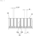
- the diameter d1 of the resin-contact-side hole 103a is 10 to 80 um
- the diameter d2 of the physical foaming agent introduction hole 103b is 20 to 400 um.
- the resin-contact-side hole 103a and the physical foaming agent introduction hole 103b have respective circular cross-sectional shapes in the present embodiment.
- the shapes of these holes are not limited to the circular shapes.
- Each of the resin-contact-side hole 103a and the physical foaming agent introduction hole 103b may have a triangular shape, a polygonal shape of a quadrangle or more, an oval shape, an elliptical shape, a cloud shape, a star shape, or the like, and these shapes may mixedly exist as appropriate.
- the diameter of the resin-contact-side hole 103a is defined as the diameter of a perfect circle having an area equal to the area of the cross section of the resin-contact-side hole 103a
- the diameter of the physical foaming agent introduction hole 103b is defined as the diameter of a perfect circle having an area equal to the area of the cross section of the physical foaming agent introduction hole 103b.
- the inner peripheral surface of the resin-contact-side hole 103a and the inner peripheral surface of the physical foaming agent introduction hole 103b are formed straight in the axial direction.
- the formation of the inner peripheral surfaces is not limited to this formation.
- the inner peripheral surface of the physical foaming agent introduction hole 103b may be formed to be inclined with respect to the axial direction.
- the physical foaming agent introduction hole 103b is formed to cause the diameter thereof to gradually decrease toward the resin-contact-side hole 103a.
- Fig. 7(a) the inner peripheral surface of the physical foaming agent introduction hole 103b may be formed to be inclined with respect to the axial direction.
- the physical foaming agent introduction hole 103b is formed to cause the diameter thereof to gradually decrease toward the resin-contact-side hole 103a.
- the inner peripheral surface of the physical foaming agent introduction hole 103b and the inner peripheral surface of the resin-contact-side hole 103a may be formed to be inclined with respect to the axial direction.
- the physical foaming agent introduction hole 103b is formed to cause the diameter thereof to gradually decrease toward the resin-contact-side hole 103a
- the resin-contact-side hole 103a is formed to cause the diameter thereof to gradually decrease away from the physical foaming agent introduction hole 103b.
- the diameter of the inlet side thereof from which the physical foaming agent is introduced is the maximum diameter.
- the diameter of the inlet side thereof from which the physical foaming agent is introduced is the maximum diameter
- the diameter of the resin-contact-side hole 103a the diameter of the inlet side thereof axially adjacent to the physical foaming agent introduction hole 103b is the maximum diameter.
- the diameter of a resin-contact-side hole is 0.1 mm (100 um), and the diameter of a physical foaming agent introduction hole is 0.2 mm (200 um). That is, the diameter of the resin-contact-side hole is outside the scope of the present invention, and the diameter of the physical foaming agent introduction hole is within the scope of the present invention.
Landscapes
- Molding Of Porous Articles (AREA)
- Injection Moulding Of Plastics Or The Like (AREA)
Abstract
Description
- The present invention relates to a physical foaming agent introduction filter, and an apparatus and a method for producing a foamed molded product.
- As a method for foam injection molding using nitrogen or carbon dioxide as a physical foaming agent, there is a method in which a high-pressure fluid to be a supercritical fluid is dissolved by shearing and kneading with molten resin. On the other hand, Patent Literature 1 discloses a method for molding a foamed molded product, using relatively low-pressure nitrogen, carbon dioxide, or the like without requiring a supercritical fluid. According to this method, without using a special high-pressure apparatus, fine foam cells can be formed in a molded product by a simple process with a low-pressure physical foaming agent.
- A method for producing a foamed molded product described in Patent Literature 1 is a method for producing a foamed molded product, by using a production apparatus including: a plasticizing cylinder having a plasticization zone in which thermoplastic resin is plasticized and melted to become molten resin, and a starvation zone in which the molten resin is brought into a starved state, the plasticizing cylinder including an introduction port, formed in the plasticizing cylinder, that is configured to introduce a physical foaming agent into the starvation zone; and an introduction speed adjustment container connected to the introduction port. The method includes: plasticizing and melting the thermoplastic resin to form the molten resin, in the plasticization zone; supplying a pressurized fluid including the physical foaming agent at a fixed pressure to the introduction speed adjustment container, and introducing the pressurized fluid at the fixed pressure from the introduction speed adjustment container into the starvation zone, to maintain the starvation zone at the fixed pressure; bringing the molten resin into a starved state, in the starvation zone; bringing, while maintaining the starvation zone at the fixed pressure, the molten resin in the starved state into contact with the pressurized fluid, in the starvation zone; and molding the molten resin brought into contact with the pressurized fluid including the physical foaming agent into a foamed molded product.
- Patent Literature 1:
JP 6777553 B2 - In the conventional method for producing a foamed molded product described above, in the foam molding, there is a case in which a vent-up phenomenon may occur in which molten resin in the starvation zone flows backward into the introduction port for introducing the physical foaming agent, opening to the starvation zone provided in the cylinder. In this case, the molten resin may solidify to remain in the introduction port. If the solidifying resin remains in the introduction port, the physical foaming agent cannot be stably supplied. Thus, it is necessary to remove the remaining resin, which requires time and effort.
- In addition, gas in the plasticizing cylinder is degassed at the time of cleaning or the like after the completion of molding of a foamed product, gas (a physical foaming agent) stored in the introduction speed adjustment container is introduced all at once into the plasticizing cylinder. Thus, there is a case in which a loud foaming sound may be generated.
- The present invention has been made in view of the above circumstances. It is an object of the present invention to provide a physical foaming agent introduction filter, and an apparatus and a method for producing a foamed molded product, capable of reducing a vent-up phenomenon and stably supplying a physical foaming agent to a starvation zone (a zone in which molten resin in a starved state exists).
- It is another object of the present invention to provide an apparatus and a method for producing a foamed molded product, capable of reducing generation of a loud foaming sound at the time of cleaning or the like after completion of molding of a foamed product.
- To solve the above problems, a physical foaming agent introduction filter according to the present invention, used when a physical foaming agent is introduced into molten resin in a starved state, includes:
- a filter body; and
- a plurality of fine holes provided in the filter body to pass through the filter body in a thickness direction of the filter body,
- wherein each of the fine holes includes:
- a resin-contact-side hole that opens toward one surface side of the filter body, and that is adapted to be in contact with the molten resin; and
- a physical foaming agent introduction hole that opens toward another surface side of the filter body, and that communicates with the resin-contact-side hole, to allow the physical foaming agent to be introduced into the physical foaming agent introduction hole, and
- wherein the resin-contact-side hole has a diameter that is equal to or smaller than a diameter of the physical foaming agent introduction hole, and that is 10 to 80 um.
- Here, the diameter of the resin-contact-side hole is defined as 10 to 80 um, because it is technically difficult to form the resin-contact-side hole to have a diameter of smaller than 10 um, and because, when the diameter of the resin-contact-side hole exceeds 80 pm, molten resin enters the resin-contact-side hole to solidify and the resin-contact-side hole is likely to be clogged.
- In the present invention, the diameter of the resin-contact-side hole of the physical foaming agent introduction filter is equal to or smaller than the diameter of the physical foaming agent introduction hole, and is 10 to 80 um. Thus, it is possible to reduce entrance of the molten resin into the resin-contact-side hole. Therefore, the molten resin does not solidify and does not remain in an introduction port in which the physical foaming agent introduction filter is provided. In addition, it is possible to reliably introduce the physical foaming agent into the molten resin in the starved state, from the physical foaming agent introduction hole through the resin-contact-side hole. Therefore, it is possible to reduce a vent-up phenomenon and stably supply the physical foaming agent to the molten resin in the starved state.
- Further, in the configuration according to the present invention, the diameter of the physical foaming agent introduction hole may be 20 to 400 um.
- Here, the diameter of the physical foaming agent introduction hole is defined as 20 to 400 um, because, when the diameter of the physical foaming agent introduction hole is smaller than 20 um, the flow of a physical foaming agent is lowered to make it difficult to reliably introduce the physical foaming agent into molten resin in a starved state, and because, when the diameter of the physical foaming agent introduction hole exceeds 400 um, the diameter of the physical foaming agent introduction hole becomes excessively large and the number of physical foaming agent introduction holes is reduced.
- According to such a configuration, it is possible to reliably and stably introduce a physical foaming agent into molten resin in a starved state.
- Further, in the configuration according to the present invention, the plurality of the fine holes may be provided at predetermined intervals longitudinally and laterally, and each of a thickness of a separation wall between the physical foaming agent introduction holes longitudinally adjacent to each other and a thickness of a separation wall between the physical foaming agent introduction holes laterally adjacent to each other may be 0.01 to 1.0 mm.
- Here, the thicknesses of the separation walls between the physical foaming agent introduction holes longitudinally and laterally adjacent to each other are defined as 0.01 to 1.0 mm, because, when the thicknesses of the separation walls are thinner than 0.01 mm, the thicknesses of the separation walls become excessively thin to cause the strength of the physical foaming agent introduction filter to decrease, and because, when the thicknesses of the separation walls exceed 1.0 mm, the thicknesses of the separation walls become excessively thick and the number of physical foaming agent introduction holes is reduced.
- According to such a configuration, it is possible to sufficiently secure the number of physical foaming agent introduction holes while reducing a decrease in strength of the physical foaming agent introduction filter.
- An apparatus for producing a foamed molded product according to the present invention includes:
- a plasticizing cylinder having a plasticization zone in which thermoplastic resin is plasticized and melted to become molten resin, and a starvation zone in which the molten resin is brought into a starved state, the plasticizing cylinder being provided with an introduction port configured to introduce a physical foaming agent into the starvation zone;
- an introduction speed adjustment container connected to the introduction port; and
- a physical foaming agent supply mechanism connected to the introduction speed adjustment container, the physical foaming agent supply mechanism being configured to supply a physical foaming agent to the plasticizing cylinder via the introduction speed adjustment container,
- wherein the physical foaming agent introduction filter is provided in the introduction port,
- wherein a pressurized fluid including the physical foaming agent at a fixed pressure is supplied to the introduction speed adjustment container, and the pressurized fluid at the fixed pressure is introduced from the introduction speed adjustment container into the starvation zone, to maintain the starvation zone at the fixed pressure,
- wherein while the starvation zone is maintained at the fixed pressure, the molten resin in the starved state is brought into contact with the pressurized fluid including the physical foaming agent at the fixed pressure, in the starvation zone, and
- wherein the molten resin brought into contact with the pressurized fluid including the physical foaming agent is molded into a foamed molded product.
- In the present invention, the diameter of the resin-contact-side hole of the physical foaming agent introduction filter is equal to or smaller than the diameter of the physical foaming agent introduction hole, and is 10 to 80 um. Thus, it is possible to reduce entrance of the molten resin into the resin-contact-side hole. Therefore, the molten resin does not solidify and does not remain in the introduction port in which the physical foaming agent introduction filter is provided. In addition, it is possible to reliably introduce the physical foaming agent into the molten resin in the starved state, from the physical foaming agent introduction hole through the resin-contact-side hole. Therefore, it is possible to reduce a vent-up phenomenon and stably supply the physical foaming agent to the molten resin in the starvation zone.
- Further, in the configuration according to the present invention, the introduction speed adjustment container may be provided with an introduction port opening and closing mechanism capable of opening and closing the introduction port.
- According to such a configuration, when a foamed molded product is molded, the introduction port can be opened by the introduction port opening and closing mechanism, as a result of which a physical foaming agent can be stably introduced into molten resin in the starvation zone. When the plasticizing cylinder is degassed after the completion of the molding of the foamed molded product, the introduction port can be closed by the introduction port opening and closing mechanism, whereby, with the closure, gas (the physical foaming agent) stored in the introduction speed adjustment container is not introduced into the plasticizing cylinder, as a result of which generation of a loud foaming sound can be reduced.
- A method for producing a foamed molded product according to the present invention is a method for producing a foamed molded product, by using a production apparatus including:
- a plasticizing cylinder having a plasticization zone in which thermoplastic resin is plasticized and melted to become molten resin, and a starvation zone in which the molten resin is brought into a starved state, the plasticizing cylinder being provided with an introduction port configured to introduce a physical foaming agent into the starvation zone;
- an introduction speed adjustment container connected to the introduction port; and
- the physical foaming agent introduction filter provided in the introduction port, and
- the method includes:
- plasticizing and melting the thermoplastic resin to form the molten resin, in the plasticization zone;
- supplying a pressurized fluid including the physical foaming agent at a fixed pressure to the introduction speed adjustment container, and introducing the pressurized fluid at the fixed pressure from the introduction speed adjustment container into the starvation zone, to maintain the starvation zone at the fixed pressure;
- bringing the molten resin into the starved state, in the starvation zone;
- bringing, while maintaining the starvation zone at the fixed pressure, the molten resin in the starved state into contact with the pressurized fluid, in the starvation zone; and
- molding the molten resin brought into contact with the pressurized fluid including the physical foaming agent into a foamed molded product.
- In the present invention, the diameter of the resin-contact-side hole of the physical foaming agent introduction filter is equal to or smaller than the diameter of the physical foaming agent introduction hole, and is 10 to 80 um. Thus, it is possible to reduce entrance of the molten resin into the resin-contact-side hole. Therefore, the molten resin does not solidify and does not remain in the introduction port in which the physical foaming agent introduction filter is provided. In addition, it is possible to reliably introduce the physical foaming agent into the molten resin in the starved state, from the physical foaming agent introduction hole through the resin-contact-side hole. Therefore, it is possible to reduce a vent-up phenomenon and stably supply the physical foaming agent to the molten resin in the starvation zone.
- Further, in the configuration according to the present invention, the introduction speed adjustment container may be provided with an introduction port opening and closing mechanism capable of opening and closing the introduction port. The introduction port may be opened by the introduction port opening and closing mechanism, when the molding into the foamed molded product is performed. The introduction port may be closed by the introduction port opening and closing mechanism, when the plasticizing cylinder is degassed after the molding into the foamed molded product has been completed.
- According to such a configuration, when a foamed molded product is molded, the introduction port can be opened by the introduction port opening and closing mechanism, as a result of which a physical foaming agent can be stably introduced into molten resin in the starvation zone. When the plasticizing cylinder is degassed after the completion of the molding of the foamed molded product, the introduction port can be closed by the introduction port opening and closing mechanism, whereby, with the closure, gas (the physical foaming agent) stored in the introduction speed adjustment container is not introduced into the plasticizing cylinder, as a result of which generation of a loud foaming sound can be reduced.
- According to the present invention, it is possible to reduce a vent-up phenomenon and stably supply a physical foaming agent to a starvation zone (a zone in which molten resin in a starved state exists).
- In addition, it is possible to reduce generation of a loud foaming sound at the time of cleaning or the like after the completion of molding of a foamed product.
-
-
Fig. 1 illustrates a first embodiment of the present invention, and is a cross-sectional view illustrating a schematic configuration of an extrusion production apparatus for a foamed molded product. -
Fig. 2 illustrates the same, and is a cross-sectional view illustrating a schematic configuration of an introduction speed adjustment container. -
Fig. 3 illustrates the same, and is a flowchart illustrating an extrusion production method for a foamed molded product. -
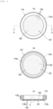
Fig. 4 illustrates the same and illustrates a physical foaming agent introduction filter, and (a) is a plan view, (b) is a bottom view, and (c) is a cross-sectional view taken along line A-A in (a). -
Fig. 5 illustrates the same, and is a cross-sectional view of relevant part of the physical foaming agent introduction filter. -
Fig. 6 illustrates the same, and is a bottom view regarding a cross-sectional view of relevant part of the physical foaming agent introduction filter. -
Fig. 7 illustrates the same and illustrates modifications of fine holes, and (a) is a cross-sectional view for a first modified example and (b) is a cross-sectional view for a second modified example. -
Fig. 8 illustrates the same and illustrates another modified example of the physical foaming agent introduction filter, and is a bottom view regarding a cross-sectional view of relevant part.
It is a schematic configuration view illustrating an extrusion production apparatus for a foamed molded product according to a second embodiment of the present invention. -
Figs. 9 illustrates a second embodiment of the present invention, and (a) is a cross-sectional view illustrating a schematic configuration of an introduction speed adjustment container in a state where an introduction port is opened, and (b) is a cross-sectional view illustrating a schematic configuration of the introduction speed adjustment container in a state where the introduction port is closed. - Hereinafter, embodiments of the present invention will be described with reference to the drawings, and the embodiments contribute to "Goal 9: Industry, Innovation and Infrastructure" of SDGs: Sustainable Development Goals, proposed by the United Nations.
- In the first embodiment, a
production apparatus 1000 illustrated inFig. 1 is used to produce a foamed molded product. Theproduction apparatus 1000 mainly includes aplasticizing cylinder 210 inside which ascrew 20 is arranged, abomb 100 that is a physical foaming agent supply mechanism for supplying a physical foaming agent to theplasticizing cylinder 210, a clamping unit (not illustrated) provided with a mold, and a controller (not illustrated) for controlling operation of theplasticizing cylinder 210 and the clamping unit. - Molten resin plasticized and melted inside the
plasticizing cylinder 210 flows from the right toward the left inFig. 1 . Thus, inside theplasticizing cylinder 210 of the present embodiment, the right inFig. 1 is defined as "upstream" or "backward", and the left inFig. 1 is defined as "downstream" or "forward". - The
plasticizing cylinder 210 has aplasticization zone 21 in which thermoplastic resin is plasticized and melted to become molten resin, and astarvation zone 23, provided on the downstream side of theplasticization zone 21, in which the molten resin is brought into a starved state. - The "starved state" is a state in which the
starvation zone 23 is not filled with the molten resin to be unfilled. In thestarvation zone 23, a space not occupied by the molten resin thus exists. Also in theplasticizing cylinder 210, anintroduction port 202 for introducing a physical foaming agent into thestarvation zone 23 is formed. An introduction speed adjustment container (pressure adjustment container) 300 is connected to theintroduction port 202. Thebomb 100 supplies a physical foaming agent into theplasticizing cylinder 210 via the introductionspeed adjustment container 300. - The
production apparatus 1000 has only onestarvation zone 23. However, the production apparatus used in the present embodiment is not limited to this configuration. For example, to enhance permeation of a physical foaming agent into molten resin, a structure may be employed that has a plurality ofstarvation zones 23 and includes a plurality ofintroduction ports 202 formed with respect to the plurality of thestarvation zones 23, allowing the physical foaming agent to be introduced into theplasticizing cylinder 210 from the plurality ofintroduction ports 202. In addition, theproduction apparatus 1000 is an injection molding apparatus. However, the production apparatus used in the present embodiment is not limited to this configuration, and may be, for example, an extrusion molding apparatus. - In the
production apparatus 1000, when thescrew 20 inside theplasticizing cylinder 210 rotates, resin pellets are plasticized and melted, and then the molten resin is fed forward inside theplasticizing cylinder 210. In addition, the molten resin is fed forward inside theplasticizing cylinder 210 by the rotation of thescrew 20. - In the upper side surface of the
plasticizing cylinder 210, aresin supply port 201 for supplying thermoplastic resin to thecylinder 210 and theintroduction port 202 for introducing a physical foaming agent into theplasticizing cylinder 210 are provided in order from the upstream side. - A
hopper 211 for supplying resin and afeed screw 212 are disposed with respect to theresin supply port 201, and the introductionspeed adjustment container 300 is connected to theintroduction port 202. - The
plasticizing cylinder 210 has theplasticization zone 21 provided on the upstream side, and thestarvation zone 23 provided on the downstream side. Theplasticization zone 21 is a zone in which thermoplastic resin is plasticized and melted to become molten resin. Thestarvation zone 23 is a zone in which the molten resin is brought into a starved state. The "starved state" refers to a state in which thestarvation zone 23 is not filled with molten resin to be unfilled, or a state in which the density of the molten resin is reduced. In thestarvation zone 23, a space not occupied by the molten resin may thus exist. - The
plasticizing cylinder 210 has, in order from the upstream side toward the downstream side, theplasticization zone 21, acompression zone 22, a flowspeed adjustment zone 25, thestarvation zone 23, and arecompression zone 24. As described above, theplasticization zone 21 is a zone in which thermoplastic resin is plasticized and melted to become molten resin. Thecompression zone 22 is a zone in which the thermoplastic resin is sheared and kneaded to be plasticized and melted, and in which the molten resin is compressed. As described above, thestarvation zone 23 is a zone in which the molten resin is brought into the starved state. Therecompression zone 24 is a zone in which the molten resin is recompressed. Note that the flowspeed adjustment zone 25 will be described later. - As described above, in the
plasticizing cylinder 210, theintroduction port 202 is provided as an opening for introducing a physical foaming agent into thestarvation zone 23. The introductionspeed adjustment container 300 is connected to theintroduction port 202. Thebomb 100 is connected to the introductionspeed adjustment container 300 by piping 154 via apressure reducing valve 151, apressure gauge 152, and anopen valve 153. Thebomb 100 is configured to supply a physical foaming agent into thecylinder 210 via the introductionspeed adjustment container 300. - At a
nozzle tip 29 of theplasticizing cylinder 210, a shut-offvalve 28 is provided which opens and closes by driving an air cylinder, and the inside of theplasticizing cylinder 210 can be maintained at a high pressure. The mold (not illustrated) is brought into close contact with thenozzle tip 29, and a cavity formed by the mold is filled with molten resin by injection from thenozzle tip 29. - A method for producing a foamed molded product, according to the present embodiment, will be described with reference to the flowchart illustrated in
Fig. 3 . - First, thermoplastic resin is plasticized and melted to form molten resin, in the
plasticization zone 21 of the plasticizing cylinder 210 (step S1 inFig. 3 ). For the thermoplastic resin, various resins can be used in accordance with intended heat resistance and use of a molded product. - Specifically, examples of the usable thermoplastic resins include thermoplastic resins such as polypropylene, polymethyl methacrylate, polyamide, polyethylene, polycarbonate, polybutylene terephthalate, amorphous polyolefin, polyetherimide, polyethylene terephthalate, polyether ether ketone, ABS resin (acrylonitrile-butadienestyrene copolymer resin), polyphenylene sulfide, syndiotactic polystyrene, polyamide imide, polylactic acid, and polycaprolactone, and composite materials thereof. In particular, a crystalline resin is desirably used because it easily forms fine cells. These thermoplastic resins may be used alone, or may be used as a mixture of two or more thereof.
- It is also possible to use a mixture obtained by kneading these thermoplastic resins with various inorganic fillers such as glass fiber, talc, carbon fiber, and ceramic, and organic fillers such as cellulose nanofiber, cellulose, and wood flour. The thermoplastic resin is preferably mixed with an inorganic filler that functions as a foam nucleating agent, an organic filler, or an additive that increases melt tension. Mixing these can make foam cells fine. The thermoplastic resin may contain various other general-purpose additives, as necessary.
- In the
plasticizing cylinder 210 inside which thescrew 20 is arranged, the thermoplastic resin is plasticized and melted. On an outer wall surface of theplasticizing cylinder 210, a band heater (not illustrated) is disposed, whereby theplasticizing cylinder 210 is heated. In addition to this heat, shearing heat generated by rotation of thescrew 20 is added. As a result, the thermoplastic resin is plasticized and melted. - Next, a physical foaming agent at a fixed pressure is supplied to the introduction
speed adjustment container 300, and then the pressurized fluid at the fixed pressure is introduced from the introductionspeed adjustment container 300 into thestarvation zone 23, whereby the pressure in thestarvation zone 23 is maintained at the fixed pressure (step S2 inFig. 3 ). - As the physical foaming agent, a pressurized fluid is used. In the present embodiment, "fluid" means any of liquid, gas, and supercritical fluid. In addition, the physical foaming agent is preferably carbon dioxide, nitrogen, or the like from the viewpoint of cost, and a load on the environment. The pressure of the physical foaming agent used in the present embodiment is set to a relatively low pressure, and thus, for example, a fluid can be used that is extracted from the
bomb 100, such as a nitrogen bomb, a carbon dioxide bomb, or an air bomb, in which the fluid is stored, and that is then subjected to reduction in pressure to a fixed pressure through thepressure reducing valve 151. In this case, it is not necessary to provide a pressure increase apparatus, the overall cost of the production apparatus can be reduced. If necessary, a fluid whose pressure is increased to a predetermined pressure may be used as the physical foaming agent. For example, in a case where nitrogen is used as the physical foaming agent, the physical foaming agent can be produced by the following method. First, nitrogen is purified through a nitrogen separation membrane while air in the atmosphere is compressed by a compressor. Next, the purified nitrogen is subjected to an increase in pressure to a predetermined pressure using a booster pump, a syringe pump, or the like to produce a physical foaming agent. Compressed air may also be used as the physical foaming agent. In the present embodiment, the physical foaming agent and the molten resin are not subjected to forcible shearing and kneading. Thus, even when compressed air is used as the physical foaming agent, it is possible to reduce deterioration of the molten resin due to oxidation because oxygen, which has low dissolubility with respect to the molten resin, is hardly dissolved in the molten resin. - The pressure of the physical foaming agent introduced into the
starvation zone 23 is fixed, and the pressure in thestarvation zone 23 is maintained at a fixed pressure equal to the pressure of the introduced physical foaming agent. The pressure of the physical foaming agent is preferably 0.5 MPa to 30 MPa, more preferably 1 MPa to 25 MPa, and still more preferably 1 MPa to 15 MPa. Although the optimum pressure varies depending on the type of the molten resin, it is possible to cause a physical foaming agent in an amount necessary for foaming to permeate through molten resin when the pressure of the physical foaming agent is set to be equal to or higher than 1 MPa, and it is possible to improve the heat resistance of a foamed molded product when the pressure of the physical foaming agent is set to be equal to or lower than 30 MPa. Production at a pressure of higher than 12 MPa (high pressure) may be prone to generation of unmelted residues in the foaming agent. - Note that the wording the pressure of the physical foaming agent for pressurizing molten resin is "fixed" means that the fluctuation range of a pressure with respect to a predetermined pressure is preferably within ±20%, and more preferably within ±10%. The pressure in the
starvation zone 23 is measured, for example, by apressure sensor 27 provided at a position facing theintroduction port 202 of theplasticizing cylinder 210. - Further, the
starvation zone 23 moves inside theplasticizing cylinder 210 in a forward-backward direction along with forward and backward movement of thescrew 20. However, thepressure sensor 27 illustrated inFig. 1 is always provided at a position allowing thepressure sensor 27 to exist in thestarvation zone 23, within the range form the most forward position to the most backward position of thestarvation zone 23. The position facing theintroduction port 202 is also always within thestarvation zone 23. Thus, thepressure sensor 27 is not provided at the position facing theintroduction port 202, but the pressure indicated by thepressure sensor 27 and the pressure at the position facing theintroduction port 202 are substantially equal. In the present embodiment, only the physical foaming agent is introduced into thestarvation zone 23, but another pressurized fluid other than the physical foaming agent may be simultaneously introduced into thestarvation zone 23 to an extent not to affect the effect of the present invention. In this case, the pressurized fluid including the physical foaming agent introduced into thestarvation zone 23 has the fixed pressure as described above. - In the present embodiment, the physical foaming agent is supplied from the
bomb 100 to thestarvation zone 23, through theintroduction port 202 via the introductionspeed adjustment container 300. The physical foaming agent is subjected to reduction in pressure to a predetermined pressure using thepressure reducing valve 151, and is then introduced through theintroduction port 202 into thestarvation zone 23 without passing through a pressure increase apparatus or the like. In the present embodiment, control is not performed for the amount of introduction, the time of introduction, and the like of the physical foaming agent introduced into theplasticizing cylinder 210. Thus, it is not necessary to provide a mechanism for controlling these parameters, such as a drive valve using a check valve, an electromagnetic valve, or the like, and theintroduction port 202 does not include the drive valve and is always opened. In the present embodiment, by the physical foaming agent supplied from thebomb 100, a section from thepressure reducing valve 151 through the introductionspeed adjustment container 300 to thestarvation zone 23 in theplasticizing cylinder 210 is maintained at the fixed pressure of the physical foaming agent. - Further, the
introduction port 202 for the physical foaming agent has an inner diameter D1 larger than that of an introduction port for a physical foaming agent in a conventional production apparatus. Thus, even a relatively low-pressure physical foaming agent can be efficiently introduced into theplasticizing cylinder 210. Further, even if part of the molten resin comes into contact with theintroduction port 202 to be solidified, theintroduction port 202 has such a larger inner diameter D1, and thus is free from being completely clogged, thereby allowing theintroduction port 202 to function as an introduction port. For example, as the inner diameter of theplasticizing cylinder 210 becomes larger, that is, as the outer diameter of theplasticizing cylinder 210 becomes larger, it is possible to easily cause the inner diameter D1 of theintroduction port 202 to be larger. However, in a case where the inner diameter D1 of theintroduction port 202 is excessively large, the molten resin remains to cause a molding defect, and the introductionspeed adjustment container 300 connected to theintroduction port 202 becomes large in size, thereby increasing the overall cost of the apparatus. Thus, a specific size of the inner diameter D1 of theintroduction port 202 is preferably 20% to 100%, and more preferably 30% to 80% of the inner diameter of theplasticizing cylinder 210. Alternatively, the inner diameter D1 of theintroduction port 202 is preferably 3 mm to 150 mm, and more preferably 5 mm to 100 mm, without depending on the inner diameter of theplasticizing cylinder 210. - Here, as illustrated in
Fig. 2 , the inner diameter D1 of theintroduction port 202 means the inner diameter of an opening on aninner wall 210a of theplasticizing cylinder 210. The shape of theintroduction port 202, that is, the shape of the opening on theinner wall 210a of theplasticizing cylinder 210 is not limited to a perfect circle, and may also be an ellipse or a polygon. In a case where the shape of theintroduction port 202 is an ellipse or a polygon, a diameter of a perfect circle having an area equal to the area of theintroduction port 202 is defined as the "inner diameter D1 of theintroduction port 202". - Next, the introduction
speed adjustment container 300 connected to theintroduction port 202 will be described. The introductionspeed adjustment container 300 has a function of setting the pressure of the physical foaming agent and the pressure in thestarvation zone 23 in theplasticizing cylinder 210 to the same fixed pressure, and maintaining the pressure in thestarvation zone 23 at the fixed pressure. For example, if a large amount of the physical foaming agent is consumed in thestarvation zone 23, there may be a case in which the supply of the physical foaming agent cannot catch up with the consumption to rapidly decrease the pressure in thestarvation zone 23. However, with the introductionspeed adjustment container 300, the physical foaming agent can be stably supplied, thereby reducing the fluctuation in pressure in thestarvation zone 23. - Further, the introduction
speed adjustment container 300 is formed to have a certain volume or more, whereby the flow velocity of the physical foaming agent to be introduced into theplasticizing cylinder 210 is made gentle and a time during which the physical foaming agent stays inside the introductionspeed adjustment container 300 is secured. The introductionspeed adjustment container 300 is directly connected to theplasticizing cylinder 210 heated by the band heater (not illustrated) disposed in the periphery of theplasticizing cylinder 210, and heat on theplasticizing cylinder 210 is also conducted to the introductionspeed adjustment container 300. As a result, the physical foaming agent inside the introductionspeed adjustment container 300 is heated, which reduces a temperature difference between the physical foaming agent and the molten resin to prevent the temperature of the molten resin, with which the physical foaming agent comes into contact, from being extremely lowered, thereby stabilizing the amount of dissolution (amount of permeation) of the physical foaming agent in the molten resin. That is, the introductionspeed adjustment container 300 functions as a buffer container having a function of heating the physical foaming agent. On the other hand, in a case where the volume of the introductionspeed adjustment container 300 is excessively large, the overall cost of the apparatus increases. Although the volume of the introductionspeed adjustment container 300 also depends on the amount of the molten resin existing in thestarvation zone 23, the volume of the introductionspeed adjustment container 300 is preferably 5 mL to 20 L, more preferably 10 mL to 2 L, and still more preferably 10 mL to 1 L. By setting the volume of the introductionspeed adjustment container 300 within this range, it is possible to secure the time during which the physical foaming agent stays while considering the cost. - As will be described later, the physical foaming agent is consumed in the
plasticizing cylinder 210 by coming into contact with and permeating through the molten resin. To maintain the pressure in thestarvation zone 23 at a fixed pressure, a physical foaming agent at an amount equivalent to the consumed amount is introduced from the introductionspeed adjustment container 300 into thestarvation zone 23. If the volume of the introductionspeed adjustment container 300 is excessively small, the replacement of the physical foaming agent occurs more frequently. Thus, the temperature of the physical foaming agent becomes unstable, and as a result, the supply of the physical foaming agent may become unstable. Therefore, the introductionspeed adjustment container 300 preferably has a volume allowing the physical foaming agent at an amount equivalent to the amount consumed in theplasticizing cylinder 210 in 1 to 10 minutes to stay. In addition, for example, the volume of the introductionspeed adjustment container 300 is preferably 0.1 times to 5 times, more preferably 0.5 times to 2 times as large as the volume of thestarvation zone 23 to which the introductionspeed adjustment container 300 is connected. In the present embodiment, the volume of thestarvation zone 23 means the volume of a region (starvation zone 23) in which a portion of thescrew 20 where the diameter of the shaft and the depth of the screw flight are constant is located, in theplasticizing cylinder 210 that contains no molten resin to be empty. - As illustrated in
Fig. 2 , the introductionspeed adjustment container 300 mainly includes acylindrical container body 310, acoupling member 320 that couples thecontainer body 310 to theplasticizing cylinder 210, and alid 330 of thecontainer body 310. One end of thecylindrical container body 310 is connected to theintroduction port 202 through thecoupling member 320. Thestarvation zone 23 in theplasticizing cylinder 210 communicates with aninternal space 312 via theintroduction port 202. Thelid 330 is provided at the other end of the cylindrical container body (the end opposite to the introduction port 202), in a manner openable and closable. The piping 154 for supplying a physical foaming agent to theinternal space 312 is connected to thecontainer body 310. - When focusing on the shape of the
internal space 312 of the introductionspeed adjustment container 300, the introductionspeed adjustment container 300 includes a firststraight portion 31, a taperedportion 32, and a secondstraight portion 33. The firststraight portion 31 is connected to theintroduction port 202, and is formed in a cylindrical shape and has an inner diameter that does not change. The taperedportion 32 is provided adjacent to the firststraight portion 31, and has an inner diameter that increases with distance from theintroduction port 202. The secondstraight portion 33 is provided adjacent to the taperedportion 32, and is formed in a cylindrical shape and has an inner diameter that does not change. That is, as illustrated inFig. 2 , the introductionspeed adjustment container 300 has a structure in which arrangement is made to align, on a common straight line m, the central axis of the firststraight portion 31 that is a cylinder having a smaller inner diameter D1 and the central axis of the secondstraight portion 33 that is a cylinder having a larger inner diameter D2, and in which the firststraight portion 31 and the secondstraight portion 32 are connected through the tapered surface of the taperedportion 32. In the present embodiment, the extending direction of the straight line m that coincides with the central axis of the firststraight portion 31 and the central axis of the secondstraight portion 33 coincides with the extending direction of the introductionspeed adjustment container 300 having a cylindrical shape. In the present embodiment, the firststraight portion 31 is constituted by thecoupling member 320, and the taperedportion 32 and the secondstraight portion 33 are constituted by thecontainer body 310. - The
lid 330 is provided on the secondstraight portion 33 of thecontainer body 310, in a manner openable and closable. Thelid 330 is preferably openable and closable by a hand of an operator without using a special tool. In the molding of a foamed molded product, there is a case in which setting of molding conditions (condition setting) is performed in advance. In the setting of the molding conditions, the number of rotations of thefeed screw 212 or thescrew 20 is optimized, and a check is made to see whether the starved state is stably formed in thestarvation zone 23. At the same time, a check is also made to see whether the molten resin does not swell from theintroduction port 202 into the introductionspeed adjustment container 300. Accordingly, thelid 330 is preferably openable and closable by a simple method, without using a bolt, and is preferably configured to allow resin entering the introductionspeed adjustment container 300 to be removed. By allowing thelid 330 to be openable and closable by the operator's hand, work efficiency in setting the molding conditions is improved. Provision of a seal mechanism to thelid 330 is optional, but it is possible to use a seal mechanism incorporating a spring, a high-pressure seal mechanism of a clutch-type, or the like. In the present embodiment, apolyimide seal member 331 incorporating a spring is used. Theseal member 331 is expanded by the gas pressure of a physical foaming agent staying inside theinternal space 312, and the sealing performance is enhanced. - A material forming the introduction
speed adjustment container 300 preferably has pressure resistance from the viewpoint of containing a pressurized fluid, and preferably has a large thermal capacity, properties less likely to increase in temperature, and properties likely to remove heat from attached resin from the viewpoint of promoting solidification of the molten resin on the wall surface, and from the viewpoint of reducing entrance of the molten resin into the inside of the container. In addition, from the viewpoint of heating the physical foaming agent, the material forming the introductionspeed adjustment container 300 preferably has high thermal conductivity to allow heat from thecontainer body 310 to easily conduct. From these viewpoints, the introductionspeed adjustment container 300 is preferably formed of metal such as stainless steel (SUS: Steel Use Stainless) or the like. This applies similarly to thecoupling member 320. - Next, the molten resin is caused to flow to the
starvation zone 23, and the molten resin is caused to be brought into a starved state in the starvation zone 23 (step S3 inFig. 3 ). The starved state is determined by the balance between the amount of molten resin fed from the upstream side of thestarvation zone 23 to thestarvation zone 23 and the amount of molten resin fed from thestarvation zone 23 to the downstream side of thestarvation zone 23, and the starved state is obtained when the former amount is smaller. - In the present embodiment, the
compression zone 22 in which the molten resin is compressed and the pressure increases is provided upstream of thestarvation zone 23, whereby the molten resin is brought into the starved state in thestarvation zone 23. In thecompression zone 22, a large-diameter portion 20A is provided that is formed by making the diameter of the shaft of thescrew 20 larger (thicker) than that in theplasticization zone 21 located on the upstream side of thecompression zone 22, and by making the screw flight gradually shallower. Further, also in thecompression zone 22, aseal portion 26 is provided adjacent to the downstream side of the large-diameter portion 20A. In theseal portion 26, the shaft of thescrew 20 has a large (thick) diameter similarly to that in the large-diameter portion 20A, but no screw flight is provided. Instead of the screw flight, a plurality of shallow grooves are formed in the shaft of thescrew 20. By increasing the diameter of the shaft of thescrew 20 in the large-diameter portion 20A and theseal portion 26, a clearance between the inner wall of theplasticizing cylinder 210 and thescrew 20 can be reduced, and the amount of resin supplied to the downstream side can also be reduced. Thus, the flow resistance of the molten resin can be increased. Therefore, in the present embodiment, each of the large-diameter portion 20A and theseal portion 26 is a mechanism for increasing the flow resistance of the molten resin. - Note that the
seal portion 26 also has an effect of reducing a backward flow of the physical foaming agent, that is, movement of the physical foaming agent from the downstream side to the upstream side of theseal portion 26. - Thanks to the presence of the large-
diameter portion 20A and theseal portion 26, the flow rate of resin supplied from thecompression zone 22 to thestarvation zone 23 decreases, the molten resin is compressed and the pressure increases in thecompression zone 22 on the upstream side, and thestarvation zone 23 on the downstream side is unfilled with the molten resin (starved state). To enhance the starved state of the molten resin, thescrew 20 has a structure in which a portion of thescrew 20 located in thestarvation zone 23 has a smaller (thinner) shaft diameter and a deeper screw flight, compared with those in a portion of thescrew 20 located in thecompression zone 22. In addition, thescrew 20 preferably has a structure in which a portion of thescrew 20 located in thestarvation zone 23 has a smaller (thinner) shaft diameter and a deeper screw flight, across theentire starvation zone 23, compared with those in the portion of thescrew 20 located in thecompression zone 22. Further, thescrew 20 preferably has a substantially constant shaft diameter and a substantially constant screw flight depth, across theentire starvation zone 23. With such a configuration, the pressure in thestarvation zone 23 can be maintained at a substantially fixed pressure, and the starved state of the molten resin can be stabilized. In the present embodiment, as illustrated inFig. 1 , thestarvation zone 23 is formed across a portion of thescrew 20 in which the diameter of the shaft and the depth of the screw flight of thescrew 20 are constant. - The mechanism for increasing the flow resistance of the molten resin provided in the
compression zone 22 is not particularly limited as long as it is a mechanism for temporarily reducing the area of a flow path through which the molten resin passes in order to limit the flow rate of the resin supplied from thecompression zone 22 to thestarvation zone 23. In the present embodiment, both the large-diameter portion 20A of the screw and theseal portion 26 are used, but only one of them may be used. Examples of another mechanism for increasing the flow resistance, other than the large-diameter portion 20A of the screw and theseal portion 26, include a structure in which a screw flight is provided in a direction reverse to another portion, and a labyrinth structure provided on the screw. - The mechanism for increasing the flow resistance of the molten resin may be provided in the screw as a ring or the like that is a member provided separately from the screw, or may be provided integrally with the screw as a part of the structure of the screw. When the mechanism for increasing the flow resistance of the molten resin is provided as a ring or the like that is a member provided separately from the screw, the size of a clearance portion, which is a flow path of the molten resin, can be changed by replacing the ring. Thus, there is an advantage that the magnitude of the flow resistance of the molten resin can be easily changed.
- Further, other than the mechanism for increasing the flow resistance of the molten resin, the molten resin can be brought into the starved state in the
starvation zone 23 by alternatively providing, between thecompression zone 22 and thestarvation zone 23, a backflow prevention mechanism (seal mechanism) for preventing a backward flow of the molten resin from thestarvation zone 23 to thecompression zone 22 on the upstream side. An example of the backflow prevention mechanism is a seal mechanism such as a ring or a steel ball that is movable to the upstream side by the pressure of the physical foaming agent. However, the backflow prevention mechanism requires a driver, and thus there is a risk that resin might remain. Therefore, it is more preferable to provide the mechanism for increasing the flow resistance, which does not include a driver. - In the present embodiment, to stabilize the starved state of the molten resin in the
starvation zone 23, the amount of supply of the thermoplastic resin to be supplied to theplasticizing cylinder 210 may be controlled. This is because it is difficult to maintain the starved state when the amount of supply of the thermoplastic resin is excessively large. In the present embodiment, the amount of supply of the thermoplastic resin is controlled using the general-purpose feed screw 212. By limiting the amount of supply of thermoplastic resin, a metering rate of the molten resin in thestarvation zone 23 is greater than a plasticization rate in thecompression zone 22. As a result, the density of the molten resin in thestarvation zone 23 is stably reduced, and the permeation of the physical foaming agent into the molten resin is enhanced. - In the present embodiment, the length of the
starvation zone 23 in the flow direction of the molten resin is preferably long in order to secure the area and time of contact between the molten resin and the physical foaming agent. However, if the length is excessively long, an adverse effect of lengthening the molding cycle and the screw length may occur. Therefore, the length of thestarvation zone 23 is preferably 2 times to 12 times, and more preferably 4 times to 10 times as long as the size of the inner diameter of theplasticizing cylinder 210. In addition, the length of thestarvation zone 23 preferably covers the entire range of a metering stroke in injection molding. That is, the length of thestarvation zone 23 in the flow direction of the molten resin is preferably equal to or longer than the length of the metering stroke in injection molding. Thescrew 20 moves forward and backward along with plasticization and metering, and injection of the molten resin. To respond to this movement, by setting the length of thestarvation zone 23 to be equal to or longer than the length of the metering stroke, theintroduction port 202 can be arranged (formed) within thestarvation zone 23 at all times during the production of a foamed molded product. That is, even if thescrew 20 moves forward and backward during the production of a foamed molded product, the zones other than thestarvation zone 23 do not come to the position of theintroduction port 202. As a result, the physical foaming agent to be introduced through theintroduction port 202 is introduced into thestarvation zone 23 at all times during the production of a foamed molded product. By providing such a starvation zone having a sufficient and appropriate size (length) and introducing a physical foaming agent at a fixed pressure into the starvation zone, thestarvation zone 23 can be easily maintained at the fixed pressure. In the present embodiment, as illustrated inFig. 1 , the length of thestarvation zone 23 is substantially equal to the length of the portion of thescrew 20 in which the diameter of the shaft of thescrew 20 is constant and the depth of the screw flight is constant, in thescrew 20. - Further, the flow
speed adjustment zone 25 is provided between thecompression zone 22 and thestarvation zone 23. When the flow speed of the molten resin in thecompression zone 22 on the upstream side of the flowspeed adjustment zone 25 is compared with the flow speed of the molten resin in thestarvation zone 23 on the downstream side, the flow speed of the molten resin in thestarvation zone 23 is faster. The present inventors have found that foaming performance of a foamed molded product to be produced is improved by providing the flowspeed adjustment zone 25, serving as a buffer zone, between thecompression zone 22 and thestarvation zone 23, and by reducing this rapid change (increase) in the flow speed of the molten resin. Details are unknown as to the reasons why the foaming performance of a foamed molded product is improved by providing the flowspeed adjustment zone 25, serving as a buffer zone, between thecompression zone 22 and thestarvation zone 23. However, regarding one of the reasons, it is presumed that, by allowing the molten resin to stay in the flowspeed adjustment zone 25, the physical foaming agent coming in from thestarvation zone 23 and the molten resin are mixed and kneaded, and that the time of contact is lengthened. In the present embodiment, the flow speed of the molten resin is adjusted by providing a pressure reducing portion and a compressing portion in a portion of theplasticizing screw 20 located in the flowspeed adjustment zone 25 illustrated inFig. 1 , that is, by changing the depth of the screw flight, in other words, by changing the size (thickness) of the screw diameter. - Next, while the
starvation zone 23 is maintained at a fixed pressure, the molten resin in a starved state is brought into contact with the physical foaming agent at the fixed pressure, in the starvation zone 23 (step S4 inFig. 3 ). That is, in thestarvation zone 23, the molten resin is pressurized at the fixed pressure with the physical foaming agent. Thestarvation zone 23 is unfilled with the molten resin (starved state) and has a space in which the physical foaming agent can exist, and thus the physical foaming agent and the molten resin can be efficiently brought into contact with each other. The physical foaming agent in contact with the molten resin permeates through the molten resin to be consumed. When the physical foaming agent is consumed, the physical foaming agent staying in the introductionspeed adjustment container 300 is supplied to thestarvation zone 23. As a result, the pressure in thestarvation zone 23 is maintained at the fixed pressure, and the molten resin continues being in contact with the physical foaming agent at the fixed pressure. - In conventional foam molding using a conventional physical foaming agent, a predetermined amount of a high-pressure physical foaming agent is forcibly introduced into a plasticizing cylinder within a predetermined time. Thus, it is necessary to increase the pressure of the physical foaming agent to the high pressure and to accurately control the amount of introduction, the time of introduction, and the like of the physical foaming agent into the molten resin, and only the time of introduction that is short is given for allowing the physical foaming agent to come into contact with the molten resin. In contrast, in the present embodiment, instead of forcibly introducing the physical foaming agent into the
plasticizing cylinder 210, a physical foaming agent at a fixed pressure is continuously supplied into the plasticizing cylinder such that the pressure in thestarvation zone 23 is fixed, and the physical foaming agent is continuously brought into contact with the molten resin. As a result, the amount of dissolution (amount of permeation) of the physical foaming agent in the molten resin determined by a temperature and a pressure is stabilized. In addition, the physical foaming agent of the present embodiment is always in contact with molten resin, and thus a necessary and sufficient amount of the physical foaming agent can permeate through the molten resin. As a result, the foamed molded product produced in the present embodiment has fine foam cells even though a low-pressure physical foaming agent is used as compared with that of the conventional molding method using the conventional physical foaming agent. - Further, in the production method of the present embodiment, it is not necessary to control the amount of introduction, the time of introduction, and the like of the physical foaming agent. Thus, it is not necessary to provide a drive valve such as a check valve or an electromagnetic valve, and a control mechanism for controlling these, thereby enabling reducing the cost of the apparatus. In addition, the physical foaming agent used in the present embodiment has a pressure lower than that of the conventional physical foaming agent, and thus a load for the apparatus is smaller.
- In the present embodiment, the
starvation zone 23 is always maintained at a fixed pressure during the production of a foamed molded product. That is, to compensate for the physical foaming agent consumed inside the plasticizing cylinder, all the steps of the method for producing a foamed molded product are performed while continuously supplying the physical foaming agent at the fixed pressure. Further, in the present embodiment, for example, in a case where injection molding of a plurality of shots is continuously performed, molten resin for the next shot is prepared in the plasticizing cylinder during an injecting step, a cooling step of a molded product, and an extracting step of the molded product, and the molten resin for the next shot is pressurized at the fixed pressure with the physical foaming agent. That is, in the injection molding of a plurality of shots performed continuously, one cycle of injection molding including a plasticizing and metering step, the injecting step, the cooling step of a molded product, the extracting step of the molded product, and the like is performed, in a state where molten resin, and a physical foaming agent at a fixed pressure always exist and are in contact with each other, inside the plasticizing cylinder, that is, in a state where the molten resin is constantly pressurized at the fixed pressure with the physical foaming agent, inside the plasticizing cylinder. Likewise, in a case where continuous molding such as extrusion molding is performed, the molding is performed, in a state where molten resin, and a physical foaming agent at a fixed pressure always exist and are in contact with each other, inside the plasticizing cylinder, that is, in a state where the molten resin is constantly pressurized at the fixed pressure with the physical foaming agent, inside the plasticizing cylinder. - Next, the molten resin brought into contact with the physical foaming agent is molded into a foamed molded product (step S5 in
Fig. 3 ). Theplasticizing cylinder 210 used in the present embodiment has therecompression zone 24 that is arranged downstream of and adjacent to thestarvation zone 23, and in which the molten resin is compressed and the pressure increases. First, the molten resin in thestarvation zone 23 is caused to flow into therecompression zone 24 by rotation of theplasticizing screw 20. The pressure of the molten resin containing the physical foaming agent is adjusted in therecompression zone 24, and is fed forward of theplasticizing screw 20 and metered. At this time, the internal pressure of the molten resin fed forward of theplasticizing screw 20 is controlled as a screw back pressure by a hydraulic motor or an electric motor (not illustrated) connected to the backward side of theplasticizing screw 20. In the present embodiment, to stabilize resin density by causing the molten resin and the physical foaming agent to be uniformly compatible with each other without separating the physical foaming agent from the molten resin, the internal pressure of the molten resin fed forward of theplasticizing screw 20, that is, the screw back pressure is preferably controlled to be higher than the fixedly maintained pressure in thestarvation zone 23 by about 1 to 6 MPa. Note that, in the present embodiment, acheck ring 50 is provided at the tip of thescrew 20 such that the compressed resin forward of thescrew 20 does not flow backward to the upstream side. As a result, at the time of metering, the pressure in thestarvation zone 23 is not affected by the resin pressure forward of thescrew 20. - The method for molding a foamed molded product is not particularly limited, and the molded product can be molded by, for example, injection foam molding, extrusion foam molding, foam blow molding, or the like. In the present embodiment, injection foam molding is performed by filling the cavity (not illustrated) in the mold with metered molten resin by injecting the metered molten resin from the
plasticizing cylinder 210 illustrated inFig. 1 . For the injection foam molding, a short-shot method or a core-back method may be used. The short-shot method is a method in which a mold cavity is filled with molten resin having a filling volume of 75% to 95% of the volume of the mold cavity to be filled while bubbles are expanded. The core-back method is a method in which a mold cavity is filled with molten resin having a filling amount of 100% of the volume of the mold cavity and then the volume of the cavity is enlarged, causing foaming. The resulting foamed molded product contains foam cells therein. Thus, shrinkage of the thermoplastic resin during cooling is reduced, and sink marks and warpage are reduced, thereby enabling obtaining a molded product having a low specific gravity. - In the production method according to the present embodiment described above, it is not necessary to control the amount of introduction, the time of introduction, and the like of a physical foaming agent into molten resin. Thus, it is possible to omit or simplify a complex controller to reduce the cost of the apparatus. In the method for producing a foamed molded product according to the present embodiment, molten resin in a starved state and a physical foaming agent at a fixed pressure are brought into contact with each other in the
starvation zone 23 while thestarvation zone 23 is maintained at the fixed pressure. As a result, it is possible to stabilize the amount of dissolution (amount of permeation) of the physical foaming agent with respect to the molten resin with a simple mechanism. - As illustrated in
Figs. 1 and2 , theproduction apparatus 1000 of the present embodiment includes a physical foaming agent introduction filter 101 (hereinafter, abbreviated as a "filter 101" in some cases) according to the present invention. As illustrated inFig. 4 , thefilter 101 is fitted inside aholder 110. - The
filter 101 is formed in a disk shape, and is set to have a thickness of about 2 to 3 mm and a diameter of about 30 mm. - The
holder 110 is formed in a cylindrical shape. In theholder 110, a ring-shapedfitting portion 110a is formed on one end surface (a lower end surface inFig. 4(c) ) to protrude in the axial direction of theholder 110, and anannular bottom surface 110b is provided on a bottom portion of thefitting portion 110a. Thefilter 101 is fitted inside the ring-shapedfitting portion 110a coaxially therewith, and a bottom surface of thefilter 101 abuts on thebottom surface 110b, whereby thefilter 101 is positioned and fixed to thefitting portion 110a. In this state, a surface of thefilter 101 and a tip surface of thefitting portion 110a are flush with each other. - An
external thread 110c is formed on the outer peripheral surface of theholder 110. - On the other hand, as illustrated in
Fig. 2 , a diameter D1 of theintroduction port 202 of thecoupling member 320 is equal to the diameter of theholder 110, and aninternal thread 202c is formed at a lower end portion of the inner peripheral surface of theintroduction port 202. - Then, the
holder 110 holding thefilter 101 is inserted into theintroduction port 202, and theexternal thread 110c of theholder 110 is screwed into theinternal thread 202c of theintroduction port 202, whereby thefilter 101 is attached to theintroduction port 202 through theholder 110. In this state, a lower end surface of thefilter 101 and a lower end surface of thecoupling member 320 are flush with each other. Thus, thefilter 101 faces thestarvation zone 23 in theplasticizing cylinder 210. - As illustrated in
Figs. 4 and5 , thefilter 101 includes a disk-shapedfilter body 102, and a large number (a plurality) offine holes 103 provided in thefilter body 102 to pass through thefilter body 102 in the thickness direction of thefilter body 102. - Each of the
fine holes 103 includes a resin-contact-side hole 103a that opens toward one surface side of thefilter body 102 and is adapted to be in contact with molten resin, and a physical foamingagent introduction hole 103b that opens toward the other surface side of thefilter body 102 and communicates with the resin-contact-side hole 103a to allow a physical foaming agent to be introduced into the physical foamingagent introduction hole 103b. - Further, the
filter 101 is formed of a metal fine penetrating porous material produced using a metal 3D printer. - That is, as one of methods for producing a three-dimensionally shaped object in a three-dimensionally shaping apparatus for producing a metal three-dimensionally shaped object, that is, a so-called metal 3D printer, a metal powder additive manufacturing method is known. In this method, a three-dimensionally shaped object is produced by laminating sintered layers through repeated cycles in each of which a powder layer is formed by uniformly applying metal material powder and the material powder within a predetermined irradiation region on the powder layer is then melted and solidified by irradiating the predetermined irradiation region with a laser beam or an electron beam.
- In the present embodiment, while the
filter body 102 is produced in the metal powder additive manufacturing method, the large number offine holes 103 including the resin-contact-side holes 103a and the physical foaming agent introduction holes 103b are formed. - The
filter 101 is not limited to a filter formed of metal, and may be formed of resin. - The resin-contact-
side hole 103a and the physical foamingagent introduction hole 103b are coaxially arranged, and the diameter of the resin-contact-side hole 103a is equal to or smaller than the diameter of the physical foamingagent introduction hole 103b. In the present embodiment, as illustrated inFigs. 5 and6 , the diameter of the resin-contact-side hole 103a is set to be smaller than the diameter of the physical foamingagent introduction hole 103b (for example, the diameter of the resin-contact-side hole 103a is set to be about one-half of the diameter of the physical foamingagent introduction hole 103b). In addition, the axial length of the resin-contact-side hole 103a is shorter than the axial length of the physical foamingagent introduction hole 103b. - Further, the diameter d1 of the resin-contact-
side hole 103a is 10 to 80 um, and the diameter d2 of the physical foamingagent introduction hole 103b is 20 to 400 um. - Here, the diameter d1 of the resin-contact-
side hole 103a is defined as 10 to 80 um, because it is technically difficult to form the resin-contact-side hole to have a diameter of smaller than 10 um, and because, when the diameter d1 of the resin-contact-side hole 103a exceeds 80 um, molten resin enters the resin-contact-side hole 103a to solidify and the resin-contact-side hole 103a is likely to be clogged. - In addition, the diameter d2 of the physical foaming
agent introduction hole 103b is defined as 20 to 400 um, because, when the diameter d2 of the physical foaming agent introduction hole is smaller than 20 um, the flow of a physical foaming agent is lowered to make it difficult to reliably introduce the physical foaming agent into molten resin in a starved state, and because, when the diameter d2 exceeds 400 um, the diameter of the physical foamingagent introduction hole 103b becomes excessively large and the number of physical foamingagent introduction holes 103b is reduced. - Further, the resin-contact-
side hole 103a and the physical foamingagent introduction hole 103b have respective circular cross-sectional shapes in the present embodiment. However, the shapes of these holes are not limited to the circular shapes. Each of the resin-contact-side hole 103a and the physical foamingagent introduction hole 103b may have a triangular shape, a polygonal shape of a quadrangle or more, an oval shape, an elliptical shape, a cloud shape, a star shape, or the like, and these shapes may mixedly exist as appropriate. - In a case where the cross-sectional shapes of the resin-contact-
side hole 103a and the physical foamingagent introduction hole 103b are not circular, the diameter of the resin-contact-side hole 103a is defined as the diameter of a perfect circle having an area equal to the area of the cross section of the resin-contact-side hole 103a, and the diameter of the physical foamingagent introduction hole 103b is defined as the diameter of a perfect circle having an area equal to the area of the cross section of the physical foamingagent introduction hole 103b. - In the present embodiment, the inner peripheral surface of the resin-contact-
side hole 103a and the inner peripheral surface of the physical foamingagent introduction hole 103b are formed straight in the axial direction. However, the formation of the inner peripheral surfaces is not limited to this formation. For example, as illustrated inFig. 7(a) , the inner peripheral surface of the physical foamingagent introduction hole 103b may be formed to be inclined with respect to the axial direction. In this case, the physical foamingagent introduction hole 103b is formed to cause the diameter thereof to gradually decrease toward the resin-contact-side hole 103a. As illustrated inFig. 7(b) , the inner peripheral surface of the physical foamingagent introduction hole 103b and the inner peripheral surface of the resin-contact-side hole 103a may be formed to be inclined with respect to the axial direction. In this case, the physical foamingagent introduction hole 103b is formed to cause the diameter thereof to gradually decrease toward the resin-contact-side hole 103a, and the resin-contact-side hole 103a is formed to cause the diameter thereof to gradually decrease away from the physical foamingagent introduction hole 103b. - In the case illustrated in
Fig. 7(a) , for the diameter of the physical foamingagent introduction hole 103b, the diameter of the inlet side thereof from which the physical foaming agent is introduced is the maximum diameter. In the case illustrated inFig. 7(b) , for the diameter of the physical foamingagent introduction hole 103b, the diameter of the inlet side thereof from which the physical foaming agent is introduced is the maximum diameter, and for the diameter of the resin-contact-side hole 103a, the diameter of the inlet side thereof axially adjacent to the physical foamingagent introduction hole 103b is the maximum diameter. - As illustrated in
Fig. 6 , the plurality (a large number) offine holes 103 are provided at predetermined intervals longitudinally and laterally on the surface of the disk-shapedfilter body 102, and a pitch P1 between the fine holes 103,103 longitudinally adjacent to each other is equal to a pitch P2 between the fine holes 103,103 laterally adjacent to each other. However, the pitch P1 and the pitch P2 may be different from each other. - In addition, each of a thickness t1 of a separation wall between the physical foaming agent introduction holes 103b, 103b longitudinally adjacent to each other, and a thickness t2 of a separation wall between the physical foaming agent introduction holes 103b, 103b laterally adjacent to each other is 0.01 to 1.0 mm.
- Here, the thicknesses t1, t2 of the separation walls between the physical foaming agent introduction holes 103b, 103b longitudinally and laterally adjacent to each other are defined as 0.01 to 1.0 mm, because, when the thicknesses t1, t2 of the separation walls are thinner than 0.01 mm, the thicknesses t1, t2 of the separation walls become excessively thin to cause the strength of the physical foaming
agent introduction filter 101 to decrease, and because, when the thicknesses t1, t2 of the separation walls exceed 1.0 mm, the thicknesses of the separation walls t1, t2 become excessively thick and the number of physical foamingagent introduction holes 103b is reduced. - In the present embodiment, the plurality (a large number) of
fine holes 103 are arranged longitudinally and laterally. However, the arrangement of thefine holes 103 is not limited to this arrangement. For example, as illustrated inFig. 8 , thefine holes 103 are arranged in a staggered pattern, and the physical foaming agent introduction holes 103b, 103b longitudinally adjacent to each other may be arranged to longitudinally partially overlap with each other. With this arrangement, it is possible to increase the number offine holes 103 per unit area. - In this case, a thickness t3 of the separation wall between the physical foaming agent introduction holes 103b, 103b obliquely adjacent to each other is preferably thinner than the thickness t2 of the separation wall between the physical foaming agent introduction holes 103b, 103b laterally adjacent to each other. In addition, the thickness t3 of the separation wall between the physical foaming agent introduction holes 103b, 103b obliquely adjacent to each other is 0.01 to 1.0 mm.
- According to the present embodiment, the diameter of the resin-contact-
side hole 103a of the physical foamingagent introduction filter 101 is equal to or smaller than the diameter of the physical foamingagent introduction hole 103b, and is 10 to 80 um. Thus, by providing such a physical foamingagent introduction filter 101 in theintroduction port 202 for introducing a physical foaming agent into thestarvation zone 23 in theplasticizing cylinder 210, it is possible to reduce entrance of molten resin existing in thestarvation zone 23 into the resin-contact-side holes 103a. Therefore, the molten resin does not solidify and does not remain in theintroduction port 202 in which the physical foamingagent introduction filter 101 is provided. - In addition, the physical foaming agent can be reliably introduced into the molten resin in the starved state (starvation zone 23), from the
introduction port 202 through the resin-contact-side holes 103a. - Therefore, it is possible to reduce a vent-up phenomenon and stably supply the physical foaming agent to the molten resin in the starved state (starvation zone 23).
- Further, the diameter of the physical foaming
agent introduction hole 103b is 20 to 400 um. Thus, it is possible to reliably and stably introduce the physical foaming agent into the molten resin in the starved state (starvation zone 23). - In addition, each of the separation wall t1 between the physical foaming agent introduction holes 103b, 103b longitudinally adjacent to each other and the thickness t2 of the separation wall between the physical foaming agent introduction holes 103b, 103b laterally adjacent to each other is 0.01 to 1.0 mm. Thus, it is possible to sufficiently secure the number of physical foaming agent introduction holes 103b while reducing a decrease in strength of the physical foaming
agent introduction filter 101. - Next, examples will be described.
- Each of foamed molded products was produced using the production apparatus for producing a foamed molded product including a corresponding one of the physical foaming agent introduction filters 101 according to the present invention described above (Examples 1 to 5).
- On the other hand, each of foamed molded products was produced using a production apparatus for producing a foamed molded product including a corresponding one of physical foaming agent introduction filters that are different from the filter according to the present invention (Comparative Examples 1 and 2).
- Then, for each of the examples and the comparative examples, confirmation was made as to pressure stability in the starvation zone, and a maintenance cycle (the number of shots, where one cycle in which one foamed molded product is produced is counted as one shot). An increase in the number of maintenance cycles means that molten resin is less likely to enter the
introduction port 202, that clogging by the resin does not occur, and that foamed molded products can be produced for a long time period. - In addition, in the item of "Pressure stability in starvation zone" in Table 1, "o ±3% (6%, 5%, 8%)" means that the pressure in the starvation zone is stably maintained within a range of ±3% (6%, 5%, 8%) with respect to a fixed pressure o.
- The results are shown in Table 1.
[Table 1] Diameter of resin-contact-side hole (mm) Depth 0.1 mm Diameter of physical foaming agent introduction hole (mm) Pitch (mm) Minimum separation wall (mm) Number of physical foaming agent introduction holes per square centimeter Pressure stability in starvation zone Maintenance cycle Example 1 0.02 0.2 0.5 0.1 1,089 20% collapsed ○ ± 3% 200,000 shots Example 2 0.08 Upper limit 0.2 0.5 0.1 1,089 5% collapsed ○ ± 6% 20,000 Example 3 0.05 Average diameter 0.1 0.3 0.1 2,500 15% collapsed ○ ± 5% 100,000 Example 4 0.02 0.02 0.1 0.06 15,625 30% collapsed ○ ± 5% 200,000 Example 5 0.03 0.4 0.9 0.1 400 30% collapsed ○ ± 8% 170,000 Comparative Example 1 0.1 0.2 0.5 0.1 1,089 Not collapsed at all × Clogged at 100th shot 500 shots Comparative Example 2 0.03 0.5 1.1 0.1 256 × ± 12% 170,000 - In each of Examples 1 to 5, the diameter of a resin-contact-side hole is within a range of 10 to 80 um, and the diameter of a physical foaming agent introduction hole is within a range of 20 to 400 um, both of which are within the scope of the present invention.
- On the other hand, in Comparative Example 1, the diameter of a resin-contact-side hole is 0.1 mm (100 um), and the diameter of a physical foaming agent introduction hole is 0.2 mm (200 um). That is, the diameter of the resin-contact-side hole is outside the scope of the present invention, and the diameter of the physical foaming agent introduction hole is within the scope of the present invention.
- In Comparative Example 2, the diameter of a resin-contact-side hole is 0.03 mm (30 um), and the diameter of a physical foaming agent introduction hole is 0.5 mm (500 um). That is, the diameter of the resin-contact-side hole is within the scope of the present invention, and the diameter of the physical foaming agent introduction hole is outside the scope of the present invention.
- As illustrated in Table 1, it can be seen that in each of Examples 1 to 5, the pressure in the starvation zone can be stably maintained at a fixed pressure and the maintenance cycle is also lengthened.
- Thus, it is possible to reduce entrance of molten resin into the resin-contact-side holes and clogging of the resin-contact-side holes, and it is also possible to reliably introduce a physical foaming agent into molten resin in a starved state from the physical foaming agent introduction holes through the resin-contact-side holes.
- In contrast, in Comparative Example 1, the diameter of the resin-contact-side hole is 0.1 mm (100 um), which is larger than that in each of Examples 1 to 5. Thus, the molten resin enters and solidifies in the resin-contact-side holes, and the pressure in the starvation zone cannot be stably maintained at a fixed pressure. In addition, the maintenance cycle is about 500 shots, which is shorter. Further, in Comparative Example 2, the diameter of the physical foaming agent introduction hole is 0.5 mm (500 um), which is larger than that in each of Examples 1 to 5. Thus, the number of physical foaming agent introduction holes (the number per unit area) is reduced. Therefore, it is difficult to reliably introduce a physical foaming agent, and the pressure stability in the starvation zone becomes lower than that in each of Examples 1 to 5.
- Next, a second embodiment will be described.
-
Fig. 9 includes cross-sectional views each illustrating an introductionspeed adjustment container 300 in a production apparatus according to the second embodiment. - The second embodiment is different from the first embodiment in that an introduction port opening and
closing mechanism 250 that can open and close theintroduction port 202 is provided in the introductionspeed adjustment container 300. Thus, this point will be described below, and the same configurations as those of the first embodiment may be denoted by the same reference signs and the description thereof may be omitted. - When gas in the
plasticizing cylinder 210 is degassed at the time of cleaning or the like after the completion of molding of a foamed product using theproduction apparatus 1000, gas (a physical foaming agent) stored in the introductionspeed adjustment container 300 is introduced all at once into theplasticizing cylinder 210. Thus, there is a case in which a loud discharge sound is generated. - The introduction port opening and
closing mechanism 250 is provided to reduce this foaming sound. Hereinafter, the configuration of the introduction port opening andclosing mechanism 250 will be described. - As illustrated in
Fig. 9 , the introduction port opening andclosing mechanism 250 includes anair cylinder 251, and apiston 252 provided to theair cylinder 251. - The
air cylinder 251 is formed in a cylindrical shape, and has a lower end fixed to an upper surface of thelid 330 of the introductionspeed adjustment container 300. - The
piston 252 includes a disk-shapedflange 252a that can axially reciprocate inside theair cylinder 251, and apiston rod 252b having a base end (upper end inFig. 9 ) fixed to a central portion of a lower surface of theflange 252a. In addition, a packingmember 252c in close contact with the inner peripheral surface of theair cylinder 251 in a manner axially slidable is attached to an outer peripheral portion of theflange 252a. - The
air cylinder 251 is configured to be able to alternately take in and out compressed air to and from the upper side and the lower side of theflange 252a, inside theair cylinder 251. With this configuration, theflange 252a can reciprocate in the axial direction. - A through
hole 330a is formed in a central portion of thelid 330 to pass therethrough in the axial direction of thepiston rod 252b, and thepiston rod 252b is inserted through the throughhole 330a to be able to reciprocate in the axial direction. A packingmember 252d in close contact with the inner peripheral surface of the throughhole 330a in a manner axially slidable is attached to an outer peripheral portion of thepiston rod 252b. - Further, a
plug member 253 that opens and closes theintroduction hole 202 is provided integrally with thepiston rod 252b at a tip end (lower end inFig. 9 ) of thepiston rod 252b. Theplug member 253 is formed in a truncated cone shape, and has an outer peripheral surface formed as an inclined surface whose diameter gradually decreases toward a tip end (lower end) thereof. - On the other hand, in the
coupling member 320 forming theintroduction hole 202, a receivingsurface 320a having a conical-surface-like shape is formed on the inlet side (upper end side inFig. 9 ) of theintroduction hole 202. The receivingsurface 320a is formed as an inclined surface whose diameter gradually increases toward the upper side thereof. The inclined surface of the receivingsurface 320a and the inclined surface of theplug member 253 are inclined at the same angle with respect to the straight line m. - As illustrated in Fig. 9(a), in a state where the
piston 252 is drawn up, that is, in a state where theflange 252a is located on the inner upper surface side of theair cylinder 251, theplug member 253 is located at a position separated upward from theintroduction hole 202, and a physical foaming agent can be supplied from the introductionspeed adjustment container 300 into theintroduction port 202. - On the other hand, as illustrated in
Fig. 9(b) , in a state where thepiston 252 is pushed down, that is, in a state where theflange 252a is located on the inner lower surface side of theair cylinder 251, theplug member 253 enters theintroduction port 202 to cause the outer peripheral surface of theplug member 253 to come into close contact with the receivingsurface 320a and to seal theintroduction port 202. - By the
production apparatus 1000 including the introductionspeed adjustment container 300 provided with such an introduction port opening andclosing mechanism 250, the followings can be achieved. That is, when a foamed molded product is molded, theintroduction port 202 can be opened to be in an opened state by the introduction port opening andclosing mechanism 250, as a result of which a physical foaming agent can be stably introduced into molten resin in thestarvation zone 23. When theplasticizing cylinder 210 is degassed after the completion of the molding of the foamed molded product, theintroduction port 202 can be closed to be sealed by the introduction port opening andclosing mechanism 250, whereby, with the closure, gas (a physical foaming agent) stored in the introductionspeed adjustment container 300 is not introduced into theplasticizing cylinder 210, as a result of which generation of a loud foaming sound can be reduced. - In the present embodiment, the physical foaming
agent introduction filter 101 is provided in theintroduction port 202, in theproduction apparatus 1000 including the introductionspeed adjustment container 300 provided with the introduction port opening andclosing mechanism 250. However, in the case of reducing the foaming sound as described above, the application of the present embodiment may be made to a production apparatus for producing a foamed molded product in which the physical foamingagent introduction filter 101 is not provided in theintroduction port 202. -
- 21 plasticization zone
- 23 starvation zone
- 100 bomb (physical foaming agent supply mechanism)
- 101 filter
- 102 filter body
- 103 fine hole
- 103a resin-contact-side hole
- 103b physical foaming agent introduction hole
- 202 introduction port
- 210 plasticizing cylinder
- 250 introduction port opening and closing mechanism
- 300 introduction speed adjustment container
- 1000 production apparatus
Claims (7)
- A physical foaming agent introduction filter used when a physical foaming agent is introduced into molten resin in a starved state, the filter comprising:a filter body; anda plurality of fine holes provided in the filter body to pass through the filter body in a thickness direction of the filter body,wherein each of the fine holes includes:a resin-contact-side hole that opens toward one surface side of the filter body, and that is adapted to be in contact with the molten resin; anda physical foaming agent introduction hole that opens toward another surface side of the filter body, and that communicates with the resin-contact-side hole, to allow the physical foaming agent to be introduced into the physical foaming agent introduction hole, andwherein the resin-contact-side hole has a diameter that is equal to or smaller than a diameter of the physical foaming agent introduction hole, and that is 10 to 80 um.
- The physical foaming agent introduction filter according to claim 1,
wherein the diameter of the physical foaming agent introduction hole is 20 to 400 um. - The physical foaming agent introduction filter according to claim 1 or 2,
wherein the plurality of fine holes are provided at predetermined intervals longitudinally and laterally, and each of a thickness of a separation wall between the physical foaming agent introduction holes longitudinally adjacent to each other and a thickness of a separation wall between the physical foaming agent introduction holes laterally adjacent to each other is 0.01 to 1.0 mm. - An apparatus for producing a foamed molded product, the apparatus comprising:a plasticizing cylinder having a plasticization zone in which thermoplastic resin is plasticized and melted to become molten resin, and a starvation zone in which the molten resin is brought into a starved state, the plasticizing cylinder being provided with an introduction port configured to introduce a physical foaming agent into the starvation zone;an introduction speed adjustment container connected to the introduction port; anda physical foaming agent supply mechanism connected to the introduction speed adjustment container, the physical foaming agent supply mechanism being configured to supply the physical foaming agent to the plasticizing cylinder via the introduction speed adjustment container,wherein the physical foaming agent introduction filter according to any one of claims 1 to 3 is provided in the introduction port,wherein a pressurized fluid including the physical foaming agent at a fixed pressure is supplied to the introduction speed adjustment container, and the pressurized fluid at the fixed pressure is introduced from the introduction speed adjustment container into the starvation zone, to maintain the starvation zone at the fixed pressure,wherein while the starvation zone is maintained at the fixed pressure, the molten resin in the starved state is brought into contact with the pressurized fluid including the physical foaming agent at the fixed pressure, in the starvation zone, andwherein the molten resin brought into contact with the pressurized fluid including the physical foaming agent is molded into a foamed molded product.
- The apparatus for producing a foamed molded product according to claim 4,
wherein the introduction speed adjustment container is provided with an introduction port opening and closing mechanism capable of opening and closing the introduction port. - A method for producing a foamed molded product, by using a production apparatus including:a plasticizing cylinder having a plasticization zone in which thermoplastic resin is plasticized and melted to become molten resin, and a starvation zone in which the molten resin is brought into a starved state, the plasticizing cylinder being provided with an introduction port configured to introduce a physical foaming agent into the starvation zone;an introduction speed adjustment container connected to the introduction port; andthe physical foaming agent introduction filter according to any one of claims 1 to 3 provided in the introduction port,the method comprising:plasticizing and melting the thermoplastic resin to form the molten resin, in the plasticization zone;supplying a pressurized fluid including the physical foaming agent at a fixed pressure to the introduction speed adjustment container, and introducing the pressurized fluid at the fixed pressure from the introduction speed adjustment container into the starvation zone, to maintain the starvation zone at the fixed pressure;bringing the molten resin into the starved state, in the starvation zone;bringing, while maintaining the starvation zone at the fixed pressure, the molten resin in the starved state into contact with the pressurized fluid, in the starvation zone; andmolding the molten resin brought into contact with the pressurized fluid including the physical foaming agent into a foamed molded product.
- The method for producing a foamed molded product according to claim 6,wherein the introduction speed adjustment container is provided with an introduction port opening and closing mechanism capable of opening and closing the introduction port,wherein the introduction port is opened by the introduction port opening and closing mechanism, when the molding into the foamed molded product is performed, andwherein the introduction port is closed by the introduction port opening and closing mechanism, when the plasticizing cylinder is degassed after the molding into the foamed molded product has been completed.
Applications Claiming Priority (2)
| Application Number | Priority Date | Filing Date | Title |
|---|---|---|---|
| JP2021136093A JP7519967B2 (en) | 2021-08-24 | 2021-08-24 | Filter for introducing physical foaming agent, and manufacturing device and method for foamed molded article |
| PCT/JP2022/020691 WO2023026611A1 (en) | 2021-08-24 | 2022-05-18 | Filter for introducing physical foaming agent, manufacturing device and manufacturing method for foam molded product. |
Publications (2)
| Publication Number | Publication Date |
|---|---|
| EP4393673A1 true EP4393673A1 (en) | 2024-07-03 |
| EP4393673A4 EP4393673A4 (en) | 2025-08-13 |
Family
ID=85321766
Family Applications (1)
| Application Number | Title | Priority Date | Filing Date |
|---|---|---|---|
| EP22860908.7A Pending EP4393673A4 (en) | 2021-08-24 | 2022-05-18 | Filter for introducing a physical foaming agent, manufacturing device and manufacturing method for a molded foam product |
Country Status (6)
| Country | Link |
|---|---|
| US (1) | US20240375328A1 (en) |
| EP (1) | EP4393673A4 (en) |
| JP (1) | JP7519967B2 (en) |
| KR (1) | KR20240046436A (en) |
| CN (1) | CN117836109A (en) |
| WO (1) | WO2023026611A1 (en) |
Families Citing this family (2)
| Publication number | Priority date | Publication date | Assignee | Title |
|---|---|---|---|---|
| PT4403329T (en) * | 2022-11-30 | 2026-07-16 | Comtech Chemical Co Ltd | Apparatus and method for physical foaming injection |
| JPWO2025027676A1 (en) * | 2023-07-28 | 2025-02-06 |
Family Cites Families (13)
| Publication number | Priority date | Publication date | Assignee | Title |
|---|---|---|---|---|
| DE19803362A1 (en) * | 1998-01-29 | 1999-08-05 | Sartorius Gmbh | Foamed porous membranes made of thermoplastic polymers and method and device for their production |
| JP4355409B2 (en) | 1999-10-22 | 2009-11-04 | 株式会社日本製鋼所 | Plasticizer for molding thermoplastic resin foam |
| JP2001198961A (en) | 2000-01-19 | 2001-07-24 | Meiki Co Ltd | Gas injection resin injection device and injection molding method |
| JP2002292693A (en) | 2001-03-29 | 2002-10-09 | Dainippon Ink & Chem Inc | Injection molding apparatus and method for producing molded article using the same |
| JP2004050459A (en) | 2002-07-17 | 2004-02-19 | Meiki Co Ltd | Nozzle of injection molding machine and injection molding method |
| JP2004237729A (en) * | 2003-01-15 | 2004-08-26 | Kawata Mfg Co Ltd | Extrusion foam molding equipment |
| JP2004237522A (en) | 2003-02-05 | 2004-08-26 | Asahi Kasei Chemicals Corp | Injection molding equipment |
| JP4125705B2 (en) * | 2004-09-30 | 2008-07-30 | 株式会社カワタ | Foam extrusion molding apparatus and foam extrusion molding method |
| CN1899800A (en) * | 2006-07-19 | 2007-01-24 | 北京化工大学 | Micro foaming injection moulding plasticizing device and its producing process |
| KR101607361B1 (en) * | 2012-12-12 | 2016-03-30 | (주)엘지하우시스 | Apparatus for forming macromolecule |
| JP6777553B2 (en) * | 2017-01-11 | 2020-10-28 | マクセル株式会社 | Manufacturing method and manufacturing equipment for foam molded products |
| JP2019198993A (en) * | 2018-05-15 | 2019-11-21 | 東洋機械金属株式会社 | Injection molding machine and method for producing foam molded body |
| JP6560470B1 (en) | 2019-03-08 | 2019-08-14 | 三恵技研工業株式会社 | Foam molded body manufacturing apparatus, foam molded body manufacturing method, and foam molded body manufacturing apparatus screw |
-
2021
- 2021-08-24 JP JP2021136093A patent/JP7519967B2/en active Active
-
2022
- 2022-05-18 KR KR1020237045294A patent/KR20240046436A/en active Pending
- 2022-05-18 WO PCT/JP2022/020691 patent/WO2023026611A1/en not_active Ceased
- 2022-05-18 CN CN202280057560.3A patent/CN117836109A/en active Pending
- 2022-05-18 US US18/686,186 patent/US20240375328A1/en active Pending
- 2022-05-18 EP EP22860908.7A patent/EP4393673A4/en active Pending
Also Published As
| Publication number | Publication date |
|---|---|
| KR20240046436A (en) | 2024-04-09 |
| JP2023030774A (en) | 2023-03-08 |
| EP4393673A4 (en) | 2025-08-13 |
| CN117836109A (en) | 2024-04-05 |
| US20240375328A1 (en) | 2024-11-14 |
| WO2023026611A1 (en) | 2023-03-02 |
| JP7519967B2 (en) | 2024-07-22 |
Similar Documents
| Publication | Publication Date | Title |
|---|---|---|
| CN111546561B (en) | Method and device for producing foamed molded article | |
| KR102058641B1 (en) | Method for manufacturing foamed article and apparatus | |
| CN109890588B (en) | Manufacturing method and manufacturing apparatus of foam molding | |
| JP6560470B1 (en) | Foam molded body manufacturing apparatus, foam molded body manufacturing method, and foam molded body manufacturing apparatus screw | |
| US20240375328A1 (en) | Physical foaming agent introduction filter, and apparatus and method for producing foamed molded product | |
| JP7101471B2 (en) | Manufacturing method and manufacturing equipment for foam molded products | |
| KR20190112808A (en) | Manufacturing method and apparatus for foam molding | |
| JP7390585B2 (en) | Foam molding manufacturing equipment | |
| JP7270501B2 (en) | Extrusion manufacturing device for foam molded product, extrusion manufacturing method, and screw for extrusion manufacturing device for foam molded product | |
| WO2025027676A1 (en) | Filter attachment, and device and method for manufacturing foam-molded body | |
| JP6997847B2 (en) | Manufacturing method and manufacturing equipment for foam molded products |
Legal Events
| Date | Code | Title | Description |
|---|---|---|---|
| STAA | Information on the status of an ep patent application or granted ep patent |
Free format text: STATUS: THE INTERNATIONAL PUBLICATION HAS BEEN MADE |
|
| PUAI | Public reference made under article 153(3) epc to a published international application that has entered the european phase |
Free format text: ORIGINAL CODE: 0009012 |
|
| STAA | Information on the status of an ep patent application or granted ep patent |
Free format text: STATUS: REQUEST FOR EXAMINATION WAS MADE |
|
| 17P | Request for examination filed |
Effective date: 20240307 |
|
| AK | Designated contracting states |
Kind code of ref document: A1 Designated state(s): AL AT BE BG CH CY CZ DE DK EE ES FI FR GB GR HR HU IE IS IT LI LT LU LV MC MK MT NL NO PL PT RO RS SE SI SK SM TR |
|
| DAV | Request for validation of the european patent (deleted) | ||
| DAX | Request for extension of the european patent (deleted) | ||
| A4 | Supplementary search report drawn up and despatched |
Effective date: 20250710 |
|
| RIC1 | Information provided on ipc code assigned before grant |
Ipc: B29C 44/36 20060101AFI20250704BHEP Ipc: B29C 44/00 20060101ALI20250704BHEP Ipc: B29C 45/00 20060101ALI20250704BHEP Ipc: B29C 44/34 20060101ALN20250704BHEP |
|
| GRAP | Despatch of communication of intention to grant a patent |
Free format text: ORIGINAL CODE: EPIDOSNIGR1 |
|
| STAA | Information on the status of an ep patent application or granted ep patent |
Free format text: STATUS: GRANT OF PATENT IS INTENDED |
|
| RIC1 | Information provided on ipc code assigned before grant |
Ipc: B29C 44/36 20060101AFI20260630BHEP Ipc: B29C 44/00 20060101ALI20260630BHEP Ipc: B29C 45/00 20060101ALI20260630BHEP Ipc: B29C 44/34 20060101ALN20260630BHEP |
|
| INTG | Intention to grant announced |
Effective date: 20260708 |