EP4393643A2 - Robotisches poliersystem und verfahren zur verwendung davon - Google Patents
Robotisches poliersystem und verfahren zur verwendung davon Download PDFInfo
- Publication number
- EP4393643A2 EP4393643A2 EP23220622.7A EP23220622A EP4393643A2 EP 4393643 A2 EP4393643 A2 EP 4393643A2 EP 23220622 A EP23220622 A EP 23220622A EP 4393643 A2 EP4393643 A2 EP 4393643A2
- Authority
- EP
- European Patent Office
- Prior art keywords
- tool
- abrasive belt
- disposed
- belt
- polishing
- Prior art date
- Legal status (The legal status is an assumption and is not a legal conclusion. Google has not performed a legal analysis and makes no representation as to the accuracy of the status listed.)
- Pending
Links
- 238000005498 polishing Methods 0.000 title claims abstract description 102
- 238000000034 method Methods 0.000 title claims description 34
- 239000012636 effector Substances 0.000 claims abstract description 55
- 238000009434 installation Methods 0.000 claims abstract description 22
- 230000001939 inductive effect Effects 0.000 claims description 15
- 238000007517 polishing process Methods 0.000 claims description 10
- 238000004891 communication Methods 0.000 claims description 9
- 238000003754 machining Methods 0.000 description 10
- 230000008569 process Effects 0.000 description 8
- RTAQQCXQSZGOHL-UHFFFAOYSA-N Titanium Chemical compound [Ti] RTAQQCXQSZGOHL-UHFFFAOYSA-N 0.000 description 3
- 238000010586 diagram Methods 0.000 description 3
- 239000000428 dust Substances 0.000 description 3
- 238000004519 manufacturing process Methods 0.000 description 3
- 239000000463 material Substances 0.000 description 3
- 239000002184 metal Substances 0.000 description 3
- 229910052751 metal Inorganic materials 0.000 description 3
- 238000003860 storage Methods 0.000 description 3
- 239000010936 titanium Substances 0.000 description 3
- 229910052719 titanium Inorganic materials 0.000 description 3
- 238000009530 blood pressure measurement Methods 0.000 description 2
- 230000015556 catabolic process Effects 0.000 description 2
- 238000011960 computer-aided design Methods 0.000 description 2
- 238000006731 degradation reaction Methods 0.000 description 2
- 230000006870 function Effects 0.000 description 2
- 230000006872 improvement Effects 0.000 description 2
- 238000012545 processing Methods 0.000 description 2
- 239000000872 buffer Substances 0.000 description 1
- -1 but not limited to Inorganic materials 0.000 description 1
- 238000004364 calculation method Methods 0.000 description 1
- 238000004140 cleaning Methods 0.000 description 1
- 238000001514 detection method Methods 0.000 description 1
- 238000005516 engineering process Methods 0.000 description 1
- 238000004880 explosion Methods 0.000 description 1
- 238000003384 imaging method Methods 0.000 description 1
- 229910001092 metal group alloy Inorganic materials 0.000 description 1
- 239000007769 metal material Substances 0.000 description 1
- 150000002739 metals Chemical class 0.000 description 1
- 230000009467 reduction Effects 0.000 description 1
- 238000012552 review Methods 0.000 description 1
- 230000003068 static effect Effects 0.000 description 1
- 238000013519 translation Methods 0.000 description 1
- 238000012795 verification Methods 0.000 description 1
Images



Classifications
-
- B—PERFORMING OPERATIONS; TRANSPORTING
- B24—GRINDING; POLISHING
- B24B—MACHINES, DEVICES, OR PROCESSES FOR GRINDING OR POLISHING; DRESSING OR CONDITIONING OF ABRADING SURFACES; FEEDING OF GRINDING, POLISHING, OR LAPPING AGENTS
- B24B19/00—Single-purpose machines or devices for particular grinding operations not covered by any other main group
- B24B19/14—Single-purpose machines or devices for particular grinding operations not covered by any other main group for grinding turbine blades, propeller blades or the like
-
- B—PERFORMING OPERATIONS; TRANSPORTING
- B24—GRINDING; POLISHING
- B24B—MACHINES, DEVICES, OR PROCESSES FOR GRINDING OR POLISHING; DRESSING OR CONDITIONING OF ABRADING SURFACES; FEEDING OF GRINDING, POLISHING, OR LAPPING AGENTS
- B24B19/00—Single-purpose machines or devices for particular grinding operations not covered by any other main group
- B24B19/26—Single-purpose machines or devices for particular grinding operations not covered by any other main group for grinding workpieces with arcuate surfaces, e.g. parts of car bodies, bumpers or magnetic recording heads
-
- B—PERFORMING OPERATIONS; TRANSPORTING
- B24—GRINDING; POLISHING
- B24B—MACHINES, DEVICES, OR PROCESSES FOR GRINDING OR POLISHING; DRESSING OR CONDITIONING OF ABRADING SURFACES; FEEDING OF GRINDING, POLISHING, OR LAPPING AGENTS
- B24B21/00—Machines or devices using grinding or polishing belts; Accessories therefor
- B24B21/16—Machines or devices using grinding or polishing belts; Accessories therefor for grinding other surfaces of particular shape
- B24B21/165—Machines or devices using grinding or polishing belts; Accessories therefor for grinding other surfaces of particular shape for vanes or blades of turbines, propellers, impellers, compressors and the like
-
- B—PERFORMING OPERATIONS; TRANSPORTING
- B24—GRINDING; POLISHING
- B24B—MACHINES, DEVICES, OR PROCESSES FOR GRINDING OR POLISHING; DRESSING OR CONDITIONING OF ABRADING SURFACES; FEEDING OF GRINDING, POLISHING, OR LAPPING AGENTS
- B24B21/00—Machines or devices using grinding or polishing belts; Accessories therefor
- B24B21/18—Accessories
- B24B21/20—Accessories for controlling or adjusting the tracking or the tension of the grinding belt
-
- B—PERFORMING OPERATIONS; TRANSPORTING
- B24—GRINDING; POLISHING
- B24B—MACHINES, DEVICES, OR PROCESSES FOR GRINDING OR POLISHING; DRESSING OR CONDITIONING OF ABRADING SURFACES; FEEDING OF GRINDING, POLISHING, OR LAPPING AGENTS
- B24B27/00—Other grinding machines or devices
- B24B27/0038—Other grinding machines or devices with the grinding tool mounted at the end of a set of bars
-
- B—PERFORMING OPERATIONS; TRANSPORTING
- B24—GRINDING; POLISHING
- B24B—MACHINES, DEVICES, OR PROCESSES FOR GRINDING OR POLISHING; DRESSING OR CONDITIONING OF ABRADING SURFACES; FEEDING OF GRINDING, POLISHING, OR LAPPING AGENTS
- B24B49/00—Measuring or gauging equipment for controlling the feed movement of the grinding tool or work; Arrangements of indicating or measuring equipment, e.g. for indicating the start of the grinding operation
- B24B49/10—Measuring or gauging equipment for controlling the feed movement of the grinding tool or work; Arrangements of indicating or measuring equipment, e.g. for indicating the start of the grinding operation involving electrical means
-
- B—PERFORMING OPERATIONS; TRANSPORTING
- B24—GRINDING; POLISHING
- B24B—MACHINES, DEVICES, OR PROCESSES FOR GRINDING OR POLISHING; DRESSING OR CONDITIONING OF ABRADING SURFACES; FEEDING OF GRINDING, POLISHING, OR LAPPING AGENTS
- B24B49/00—Measuring or gauging equipment for controlling the feed movement of the grinding tool or work; Arrangements of indicating or measuring equipment, e.g. for indicating the start of the grinding operation
- B24B49/12—Measuring or gauging equipment for controlling the feed movement of the grinding tool or work; Arrangements of indicating or measuring equipment, e.g. for indicating the start of the grinding operation involving optical means
-
- B—PERFORMING OPERATIONS; TRANSPORTING
- B24—GRINDING; POLISHING
- B24B—MACHINES, DEVICES, OR PROCESSES FOR GRINDING OR POLISHING; DRESSING OR CONDITIONING OF ABRADING SURFACES; FEEDING OF GRINDING, POLISHING, OR LAPPING AGENTS
- B24B49/00—Measuring or gauging equipment for controlling the feed movement of the grinding tool or work; Arrangements of indicating or measuring equipment, e.g. for indicating the start of the grinding operation
- B24B49/16—Measuring or gauging equipment for controlling the feed movement of the grinding tool or work; Arrangements of indicating or measuring equipment, e.g. for indicating the start of the grinding operation taking regard of the load
-
- B—PERFORMING OPERATIONS; TRANSPORTING
- B24—GRINDING; POLISHING
- B24B—MACHINES, DEVICES, OR PROCESSES FOR GRINDING OR POLISHING; DRESSING OR CONDITIONING OF ABRADING SURFACES; FEEDING OF GRINDING, POLISHING, OR LAPPING AGENTS
- B24B51/00—Arrangements for automatic control of a series of individual steps in grinding a workpiece
-
- B—PERFORMING OPERATIONS; TRANSPORTING
- B25—HAND TOOLS; PORTABLE POWER-DRIVEN TOOLS; MANIPULATORS
- B25J—MANIPULATORS; CHAMBERS PROVIDED WITH MANIPULATION DEVICES
- B25J11/00—Manipulators not otherwise provided for
- B25J11/005—Manipulators for mechanical processing tasks
- B25J11/0065—Polishing or grinding
-
- B—PERFORMING OPERATIONS; TRANSPORTING
- B25—HAND TOOLS; PORTABLE POWER-DRIVEN TOOLS; MANIPULATORS
- B25J—MANIPULATORS; CHAMBERS PROVIDED WITH MANIPULATION DEVICES
- B25J13/00—Controls for manipulators
- B25J13/08—Controls for manipulators by means of sensing devices, e.g. viewing or touching devices
- B25J13/087—Controls for manipulators by means of sensing devices, e.g. viewing or touching devices for sensing other physical parameters, e.g. electrical or chemical properties
-
- B—PERFORMING OPERATIONS; TRANSPORTING
- B25—HAND TOOLS; PORTABLE POWER-DRIVEN TOOLS; MANIPULATORS
- B25J—MANIPULATORS; CHAMBERS PROVIDED WITH MANIPULATION DEVICES
- B25J15/00—Gripping heads and other end effectors
- B25J15/0019—End effectors other than grippers
Definitions
- This disclosure relates generally to robotic machining systems, more particularly, to systems and methods for identifying an installation condition of an abrasive belt for the robotic polishing system.
- Robotic machining systems may be used to accomplish one or more machining (e.g., polishing) operations for the manufacture of components.
- machining e.g., polishing
- Various robotic machining systems are known in the art. While these known systems have various advantages, there is still room in the art for improvement.
- a polishing system includes an end effector and a controller.
- the end effector includes a polishing arm, a motor, a tool head, and a belt sensor.
- the polishing arm includes a motor housing at a distal end of the polishing arm.
- the motor is mounted within the motor housing.
- the tool head extends along a lengthwise axis between and to an inner end and a tip end. The inner end is disposed on the polishing arm at the motor.
- the tool head includes a belt tensioner and a roller.
- the belt tensioner includes a tool extension including the tip end. The belt tensioner is configured to bias the tip end outward from the inner end along the lengthwise axis.
- the instructions when executed by the processor, may further cause the processor to identify the installation configuration for the abrasive belt by identifying an installed condition of the abrasive belt for the measured distance less than the distance threshold value and an uninstalled condition of the abrasive belt for the measured distance greater than the distance threshold value.
- the polishing system may further include a robotic polishing assembly including a robotic arm and the end effector.
- the robotic arm may include a plurality of movable joints extending between and to a base end and a distal end.
- the end effector may be disposed at the distal end.
- the instructions when executed by the processor, may further cause the processor to control the robotic polishing assembly to prevent the robotic polishing assembly from performing a polishing process on a workpiece with the uninstalled condition identified for the abrasive belt.
- the instructions when executed by the processor, may further cause the processor to verify an abrasive belt configuration with the abrasive belt installed on the end effector.
- the abrasive belt configuration may include includes, at least, a grit of the abrasive belt.
- the proximity sensor may be configured as an inductive sensor.
- the belt sensor may include a guide tab extending outward from the motor housing.
- the guide tab may be disposed axially coincident with the lateral tab.
- the guide tab may be further disposed laterally outward of the lateral tab.
- the lateral tab may be disposed in sliding contact with the guide tab.
- the belt tensioner may further include a tool guide and a spring.
- the tool guide may include the inner end.
- the tool guide may be mounted to the motor housing.
- the spring may be positioned between the tool guide and the tool extension. The spring may be configured to bias the tool extension away from the tool guide along the lengthwise axis.
- the tool extension may include an extension body forming an internal bore of the tool extension.
- the spring and the tool guide may be disposed within the internal bore.
- a method for identifying an installation condition of an abrasive belt on a tool head of a polishing system includes biasing a tool extension of the tool head outward from a motor housing along a lengthwise axis, measuring a distance between a proximity sensor and a lateral tab.
- the proximity sensor is disposed on the motor housing and the lateral tab is disposed on the tool extension.
- the method further includes identifying an installation condition of the abrasive belt on the tool head by comparing the measured distance to a distance threshold value.
- the installation condition includes an installed condition of the abrasive belt or an uninstalled condition of the abrasive belt.
- identifying the installation condition of the abrasive belt may include identifying the installed condition of the abrasive belt for the measured distance less than or equal to the distance threshold value.
- identifying the installation condition of the abrasive belt may include identifying the uninstalled condition of the abrasive belt for the measured distance greater than or equal to the distance threshold value.
- the belt tensioner is configured to bias the tool extension outward from the inner end along the lengthwise axis.
- the tool extension extends between and to a first end and a second end.
- the tip end is disposed at the second end.
- the tool extension further includes a first lateral side and a second lateral side.
- the first lateral side and the second lateral side extend between and to the first end and the second end.
- the tool head is configured to retain an abrasive belt extending between the motor and the tip end.
- the belt sensor includes an inductive sensor and a lateral tab.
- the inductive sensor is disposed on the motor housing.
- the lateral tab is disposed on the first lateral side at the first end.
- the inductive sensor is configured to measure a distance between the inductive sensor and the lateral tab and generate an inductive sensor signal representative of the measured distance.
- the belt tensioner may further include a tool guide and a spring.
- the tool guide may include the inner end.
- the tool guide may be mounted to the motor housing.
- the spring may be positioned between the tool guide and the tool extension. The spring may be configured to bias the tool extension away from the tool guide along the lengthwise axis.
- the tool extension may include an extension body forming an internal bore of the tool extension.
- the spring and the tool guide may be within the internal bore.
- the polishing system may further include the abrasive belt installed on the tool head.
- the abrasive belt may extend between the motor and the tip end.
- the abrasive belt may compress the spring between the tool guide and the tool extension.
- the lateral tab may be disposed in sliding contact with the guide tab.
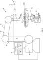
- FIG. 1 illustrates a polishing system 10 for use in the manufacture of a workpiece 1000.
- the present disclosure polishing system 10 may provide particular utility when implemented for polishing workpiece 1000 surfaces having complex curvatures, restrictive machining tolerances, and/or hard metals or metal alloys such as, but not limited to, titanium.
- the workpiece 1000 of FIG. 1 is a bladed disk ("blisk") for a gas turbine engine fan for an aircraft propulsion system.
- the present disclosure is not limited to any particular workpiece 1000 type, configuration, or material.
- the polishing system 10 is discussed herein with respect to the performance of polishing processes, aspects of the present disclosure may also be applicable to grinding or other machining processes.
- the polishing system 10 may be located within or otherwise include an enclosure (not shown) to contain dust and/or other particulate (e.g., titanium dust) which may be produced during a polishing process and which may present fire and/or explosion risk.
- dust and/or other particulate e.g., titanium dust
- the robotic polishing assembly 12 of FIG. 1 provides automated control of one or more machining tools (e.g., polishing tools) based on coded programming instructions executed by a controller (e.g., the controller 14).
- the robotic polishing assembly 12 of FIG. 1 includes a workpiece positioning fixture 18, a robotic arm 20, a force control device 21, and an end effector 22.
- this robotic polishing assembly 12 configuration of FIG. 1 is exemplary, and the present disclosure polishing system 10 is not limited to use with the particular robotic polishing assembly 12 configuration of FIG. 1 .
- the workpiece positioning fixture 18 is configured to securely retain and position the workpiece 1000 for a polishing process and/or another machining process.
- the workpiece positioning fixture 18 may be configured to rotate the workpiece 1000 a first axis 24.
- the workpiece positioning fixture 18 may additionally or alternatively be configured to rotate (e.g., tilt the workpiece 1000) about a second axis 26.
- the second axis 26 may be perpendicular to the first axis 24.
- the robotic arm 20 includes a base end 28, a distal end 30, and one or more moveable joints 32. Each movable joint 32 may be moved or otherwise controlled, for example, by an independent servo motor or other actuator (not shown).
- the distal end 30 is connected to the end effector 22.
- the robotic arm 20 is configured move the end effector 22 relative to the workpiece 1000 and/or to another component or assembly (e.g., a cleaning assembly) of the polishing system 10.
- the robotic arm 20 may be configured to move the end effector 22 along an x-axis, a y-axis, and a z-axis, as well as to rotate the end effector 22 relative to the x-axis, the y-axis, and the z-axis (e.g., pitch, yaw, and roll).
- the robotic arm 20 may be configured to move the end effector 22 along an x-axis, a y-axis, and a z-axis, as well as to rotate the end effector 22 relative to the x-axis, the y-axis, and the z-axis (e.g., pitch, yaw, and roll).
- the force control device 21 connects the robotic arm 20 to the end effector 22.
- the force control device 21 may be mounted on the distal end 30 of the robotic arm 30.
- the force control device 21 may be disposed at (e.g., on, adjacent, or proximate) the end effector 22 and may be directly or indirectly mounted to the end effector 22.
- the force control device 21 may be configured, for example, as an active contact flange including a pneumatic linear actuator (e.g., a bellow-type pneumatic linear actuator) or other linear actuator configured to translate along an axis (e.g., a single, linear axis) to control a position of the end effector 22 relative to the robotic arm 20.
- a pneumatic linear actuator e.g., a bellow-type pneumatic linear actuator
- other linear actuator configured to translate along an axis (e.g., a single, linear axis) to control a position of the end effector 22 relative to the robotic arm 20.
- the force control device 21 may additionally include a compressor and/or a pressure control assembly (e.g., a pressure control valve) configured to control an air pressure within the pneumatic linear actuator and, thereby, control a linear position of the pneumatic linear actuator including a fully extended position, a fully retracted position, or a plurality of intermediate linear positions between the fully extended position and the fully retracted position.
- the force control device 21 may additionally include a pressure sensor configured to measure an air pressure within the pneumatic linear actuator.
- the force control device 21 may be connected in signal communication with the controller 14, for example, to facilitate positional control of the force control device 21 by the controller 14 and to transmit pressure measurements from the pressure sensor to the controller 14.
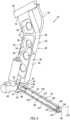
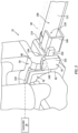
- FIGS. 2-4 illustrate perspective views of the end effector 22.
- the end effector 22 of FIGS. 2 and 3 has a first lateral side 34 and a second lateral side 36.
- the end effector 22 of FIGS. 2 and 3 includes a polishing arm 38, a motor 40, a tool head 42, an abrasive belt 44, and a belt sensor 45.
- the polishing system 10 (see FIG. 1 ) may be configured to selectively attach and detach different end effectors 22 to facilitate polishing system 10 performance of different polishing operations or to replace degraded or faulty end effectors 22.
- the angle ⁇ of the arm body 46 may facilitate positioning of the tool head 42 relative to the workpiece 1000 by the robotic arm 20 (see FIG. 1 ).
- the arm body 46 may form one or more apertures 70 extending through the arm body 46, for example, from the first lateral side 58 to the second lateral side 60.
- the apertures 70 may facilitate a reduction in weight of the arm body 46 while also facilitating access and directing pneumatic conduits, sensors cables, and the like for the end effector 22.
- the tool head 42 extends along a lengthwise axis 92 between and to an inner end 94 of the tool head 42 and a tip end 96 of the tool head 42.
- the inner end 94 is disposed at (e.g., on, adjacent, or proximate) the polishing arm 38 (e.g., the motor housing 50).
- the lengthwise axis 92 may extend orthogonally or substantially orthogonally relative to the arm body 46 (e.g., a lengthwise dimension of the second body portion 68). The present disclosure, however, is not limited to this particular orientation of the lengthwise axis 92 relative to the polishing arm 38.
- the tool extension 106 is disposed at (e.g., on, adjacent, or proximate) the tip end 96.
- the tool extension 106 extends (e.g., lengthwise) between and to a first end 114 of the tool extension 106 and a second end 116 of the tool extension 106.
- the tool extension 106 has a first lateral side 118 and a second lateral side 120.
- the first lateral side 118 and the second lateral side 120 may respectively correspond with the first lateral side 34 and the second lateral side 36.
- the tool extension 106 includes an extension body 122 extending from the first end 114 to the second end 116.
- the extension body 122 includes an exterior surface 124.
- the exterior surface 124 extends between the first end 114 and the second end 116.
- the exterior surface 124 extends circumferentially about (e.g., completely around) the lengthwise axis 92.
- the extension body 122 may generally be configured as a cylindrical body.
- the abrasive belt 44 is installed on the tool head 42 in rotational communication with the rotatable shaft 88 and the roller 100.
- the abrasive belt 44 includes an abrasive outer surface 138 which is configured for polishing, grinding, or otherwise machining one or more surfaces of a workpiece (e.g., the workpiece 1000).
- the abrasive outer surface 138 may be configured with a degree of abrasiveness (e.g., coarseness, grit, etc.) which may be selected for a particular polishing operation or workpiece surface).
- Step 602 may include verifying (e.g., with the controller 14) the end effector 22 installed on the robotic polishing assembly 12 is the correct end effector 22 (e.g., the installed end effector 22 is the end effector configuration specified by the polishing process instructions for the controller 14). Additionally or alternatively, Step 602 may include installing a new abrasive belt 44 on the tool head 42. Positioned on the tool head 42, the abrasive belt 44 may compress the belt tensioner 98 such that the biasing member 108 (see FIG. 4 ) is compressed between the tool extension 106 and the tool guide 104.
- Step 604 may additionally include verifying (e.g., with the controller 14) a belt configuration of the installed abrasive belt 44.
- the controller 14 may verify the installed abrasive belt has the correct abrasive belt 44 grit specified by the polishing process instructions for the controller 14.
- the controller 14 may verify the belt configuration of the installed abrasive belt 44 using a color detection technique.
- Step 606 includes taking one or more corrective actions for identification of an uninstalled condition for the abrasive belt 44.
- the controller 14 may control the robotic polishing assembly 12 to prevent the robotic polishing assembly 12 from performing a polishing process (e.g., on the workpiece 1000) while the abrasive belt 44 is identified in the uninstalled condition by the controller 14.
- the controller 14 may additionally or alternatively generate a notification (e.g., a warning message, a warning light, an audible alarm, etc.) for an operator of the polishing system 10.
- Step 608 includes performing a polishing operation on the workpiece 1000 with the robotic polishing assembly 12 and its end effector 22.
- the controller 14 may control the robotic polishing assembly 12 to perform a polishing operation on the workpiece 1000.
- Pressurized gas e.g., air
- the controller 14 may execute a series of instructions (e.g., a CNC polishing program) to control the robotic polishing assembly 12 to polish or otherwise machine one or more surfaces of the workpiece 1000.
Landscapes
- Engineering & Computer Science (AREA)
- Mechanical Engineering (AREA)
- Robotics (AREA)
- Human Computer Interaction (AREA)
- Finish Polishing, Edge Sharpening, And Grinding By Specific Grinding Devices (AREA)
- Constituent Portions Of Griding Lathes, Driving, Sensing And Control (AREA)
Applications Claiming Priority (1)
| Application Number | Priority Date | Filing Date | Title |
|---|---|---|---|
| US202263435537P | 2022-12-27 | 2022-12-27 |
Publications (2)
| Publication Number | Publication Date |
|---|---|
| EP4393643A2 true EP4393643A2 (de) | 2024-07-03 |
| EP4393643A3 EP4393643A3 (de) | 2024-08-28 |
Family
ID=89427237
Family Applications (1)
| Application Number | Title | Priority Date | Filing Date |
|---|---|---|---|
| EP23220622.7A Pending EP4393643A3 (de) | 2022-12-27 | 2023-12-28 | Robotisches poliersystem und verfahren zur verwendung davon |
Country Status (3)
| Country | Link |
|---|---|
| US (1) | US20240208074A1 (de) |
| EP (1) | EP4393643A3 (de) |
| CA (1) | CA3224895A1 (de) |
Family Cites Families (7)
| Publication number | Priority date | Publication date | Assignee | Title |
|---|---|---|---|---|
| US2617239A (en) * | 1949-09-14 | 1952-11-11 | Buckeye Tools Corp | Belt sander |
| JPH02131857A (ja) * | 1988-11-11 | 1990-05-21 | Hitachi Ltd | 自動研磨装置 |
| FR2677289B1 (fr) * | 1991-06-05 | 1995-12-15 | Snecma | Outil a bande abrasive et procede de changement de bande sur un tel outil. |
| US8512096B2 (en) * | 2007-12-07 | 2013-08-20 | General Electric Company | System for removing material from components |
| JP2017148931A (ja) * | 2016-02-19 | 2017-08-31 | 株式会社荏原製作所 | 研磨装置および研磨方法 |
| IT201900021444A1 (it) * | 2019-11-18 | 2021-05-18 | Sir Soc Italiana Resine Spa | Testa levigatrice a nastro |
| CN113977415B (zh) * | 2021-12-09 | 2024-10-01 | 孚坤智能科技(上海)有限公司 | 机器人手持式力控砂带机 |
-
2023
- 2023-12-27 CA CA3224895A patent/CA3224895A1/en active Pending
- 2023-12-27 US US18/397,973 patent/US20240208074A1/en active Pending
- 2023-12-28 EP EP23220622.7A patent/EP4393643A3/de active Pending
Also Published As
| Publication number | Publication date |
|---|---|
| CA3224895A1 (en) | 2024-06-27 |
| US20240208074A1 (en) | 2024-06-27 |
| EP4393643A3 (de) | 2024-08-28 |
Similar Documents
| Publication | Publication Date | Title |
|---|---|---|
| EP4393644A1 (de) | Robotisches poliersystem und verfahren zur verwendung davon | |
| US10092961B2 (en) | Drilling apparatus and method | |
| CN106003147B (zh) | 机器人系统以及异常判断方法 | |
| EP2219827B1 (de) | System zur materialabtragung aus komponenten | |
| EP3338949B1 (de) | Festwalzwerkzeug und -verfahren | |
| BR102016016884A2 (pt) | métodos para usinar uma peça de trabalho e para reparar uma ponta de aerofólio | |
| CN111618639B (zh) | 机床、加工系统、以及牵引螺栓适合与否的判定方法 | |
| US10399199B2 (en) | Inspection of drilled features in objects | |
| EP3338939B1 (de) | Festwalzwerkzeug und -verfahren | |
| EP4393643A2 (de) | Robotisches poliersystem und verfahren zur verwendung davon | |
| US20100257986A1 (en) | Apparatus and method for robotic deburr and material removal | |
| WO2016174445A1 (en) | Drilling apparatus for drilling aircraft panels | |
| CN112823079A (zh) | 用于机器人涂漆修复中的多自由度柔性致动器力控制系统和方法 | |
| EP4427880B1 (de) | Robotisches poliersystem und verfahren zur verwendung davon | |
| US12617102B2 (en) | Robotic polishing system and method for using same | |
| US20240208072A1 (en) | Robotic polishing system and method for using same | |
| US20240208073A1 (en) | Robotic polishing system and method for using same | |
| WO2016174443A1 (en) | Robotic arm end effector for drilling aircraft panels | |
| US12214454B1 (en) | System and method for machining a workpiece installed on a rotary table | |
| EP4535101A1 (de) | Bearbeitungssystem und verfahren zur validierung des betriebs einer dimensionalen messvorrichtung | |
| US20250114863A1 (en) | Assembly and method for machining a component | |
| EP3088138A1 (de) | Bohrvorrichtung zum bohren von flugzeugplatten |
Legal Events
| Date | Code | Title | Description |
|---|---|---|---|
| PUAI | Public reference made under article 153(3) epc to a published international application that has entered the european phase |
Free format text: ORIGINAL CODE: 0009012 |
|
| STAA | Information on the status of an ep patent application or granted ep patent |
Free format text: STATUS: THE APPLICATION HAS BEEN PUBLISHED |
|
| AK | Designated contracting states |
Kind code of ref document: A2 Designated state(s): AL AT BE BG CH CY CZ DE DK EE ES FI FR GB GR HR HU IE IS IT LI LT LU LV MC ME MK MT NL NO PL PT RO RS SE SI SK SM TR |
|
| PUAL | Search report despatched |
Free format text: ORIGINAL CODE: 0009013 |
|
| AK | Designated contracting states |
Kind code of ref document: A3 Designated state(s): AL AT BE BG CH CY CZ DE DK EE ES FI FR GB GR HR HU IE IS IT LI LT LU LV MC ME MK MT NL NO PL PT RO RS SE SI SK SM TR |
|
| RIC1 | Information provided on ipc code assigned before grant |
Ipc: B24B 27/00 20060101ALI20240725BHEP Ipc: B24B 21/16 20060101ALI20240725BHEP Ipc: B24B 51/00 20060101ALI20240725BHEP Ipc: B24B 49/16 20060101ALI20240725BHEP Ipc: B24B 49/12 20060101ALI20240725BHEP Ipc: B24B 49/10 20060101ALI20240725BHEP Ipc: B24B 21/20 20060101ALI20240725BHEP Ipc: B24B 19/26 20060101ALI20240725BHEP Ipc: B25J 11/00 20060101ALI20240725BHEP Ipc: B24B 19/14 20060101AFI20240725BHEP |
|
| STAA | Information on the status of an ep patent application or granted ep patent |
Free format text: STATUS: REQUEST FOR EXAMINATION WAS MADE |
|
| 17P | Request for examination filed |
Effective date: 20250228 |