EP4393640A1 - Iinformation processing device and machine tool - Google Patents
Iinformation processing device and machine tool Download PDFInfo
- Publication number
- EP4393640A1 EP4393640A1 EP22864247.6A EP22864247A EP4393640A1 EP 4393640 A1 EP4393640 A1 EP 4393640A1 EP 22864247 A EP22864247 A EP 22864247A EP 4393640 A1 EP4393640 A1 EP 4393640A1
- Authority
- EP
- European Patent Office
- Prior art keywords
- image
- unit
- correction
- processing device
- camera
- Prior art date
- Legal status (The legal status is an assumption and is not a legal conclusion. Google has not performed a legal analysis and makes no representation as to the accuracy of the status listed.)
- Pending
Links
Images




Classifications
-
- B—PERFORMING OPERATIONS; TRANSPORTING
- B23—MACHINE TOOLS; METAL-WORKING NOT OTHERWISE PROVIDED FOR
- B23Q—DETAILS, COMPONENTS, OR ACCESSORIES FOR MACHINE TOOLS, e.g. ARRANGEMENTS FOR COPYING OR CONTROLLING; MACHINE TOOLS IN GENERAL CHARACTERISED BY THE CONSTRUCTION OF PARTICULAR DETAILS OR COMPONENTS; COMBINATIONS OR ASSOCIATIONS OF METAL-WORKING MACHINES, NOT DIRECTED TO A PARTICULAR RESULT
- B23Q11/00—Accessories fitted to machine tools for keeping tools or parts of the machine in good working condition or for cooling work; Safety devices specially combined with or arranged in, or specially adapted for use in connection with, machine tools
-
- G—PHYSICS
- G06—COMPUTING OR CALCULATING; COUNTING
- G06T—IMAGE DATA PROCESSING OR GENERATION, IN GENERAL
- G06T5/00—Image enhancement or restoration
- G06T5/80—Geometric correction
-
- B—PERFORMING OPERATIONS; TRANSPORTING
- B23—MACHINE TOOLS; METAL-WORKING NOT OTHERWISE PROVIDED FOR
- B23Q—DETAILS, COMPONENTS, OR ACCESSORIES FOR MACHINE TOOLS, e.g. ARRANGEMENTS FOR COPYING OR CONTROLLING; MACHINE TOOLS IN GENERAL CHARACTERISED BY THE CONSTRUCTION OF PARTICULAR DETAILS OR COMPONENTS; COMBINATIONS OR ASSOCIATIONS OF METAL-WORKING MACHINES, NOT DIRECTED TO A PARTICULAR RESULT
- B23Q11/00—Accessories fitted to machine tools for keeping tools or parts of the machine in good working condition or for cooling work; Safety devices specially combined with or arranged in, or specially adapted for use in connection with, machine tools
- B23Q11/0042—Devices for removing chips
-
- B—PERFORMING OPERATIONS; TRANSPORTING
- B23—MACHINE TOOLS; METAL-WORKING NOT OTHERWISE PROVIDED FOR
- B23Q—DETAILS, COMPONENTS, OR ACCESSORIES FOR MACHINE TOOLS, e.g. ARRANGEMENTS FOR COPYING OR CONTROLLING; MACHINE TOOLS IN GENERAL CHARACTERISED BY THE CONSTRUCTION OF PARTICULAR DETAILS OR COMPONENTS; COMBINATIONS OR ASSOCIATIONS OF METAL-WORKING MACHINES, NOT DIRECTED TO A PARTICULAR RESULT
- B23Q17/00—Arrangements for observing, indicating or measuring on machine tools
-
- B—PERFORMING OPERATIONS; TRANSPORTING
- B23—MACHINE TOOLS; METAL-WORKING NOT OTHERWISE PROVIDED FOR
- B23Q—DETAILS, COMPONENTS, OR ACCESSORIES FOR MACHINE TOOLS, e.g. ARRANGEMENTS FOR COPYING OR CONTROLLING; MACHINE TOOLS IN GENERAL CHARACTERISED BY THE CONSTRUCTION OF PARTICULAR DETAILS OR COMPONENTS; COMBINATIONS OR ASSOCIATIONS OF METAL-WORKING MACHINES, NOT DIRECTED TO A PARTICULAR RESULT
- B23Q17/00—Arrangements for observing, indicating or measuring on machine tools
- B23Q17/24—Arrangements for observing, indicating or measuring on machine tools using optics or electromagnetic waves
-
- B—PERFORMING OPERATIONS; TRANSPORTING
- B23—MACHINE TOOLS; METAL-WORKING NOT OTHERWISE PROVIDED FOR
- B23Q—DETAILS, COMPONENTS, OR ACCESSORIES FOR MACHINE TOOLS, e.g. ARRANGEMENTS FOR COPYING OR CONTROLLING; MACHINE TOOLS IN GENERAL CHARACTERISED BY THE CONSTRUCTION OF PARTICULAR DETAILS OR COMPONENTS; COMBINATIONS OR ASSOCIATIONS OF METAL-WORKING MACHINES, NOT DIRECTED TO A PARTICULAR RESULT
- B23Q17/00—Arrangements for observing, indicating or measuring on machine tools
- B23Q17/24—Arrangements for observing, indicating or measuring on machine tools using optics or electromagnetic waves
- B23Q17/2409—Arrangements for indirect observation of the working space using image recording means, e.g. a camera
-
- B—PERFORMING OPERATIONS; TRANSPORTING
- B23—MACHINE TOOLS; METAL-WORKING NOT OTHERWISE PROVIDED FOR
- B23Q—DETAILS, COMPONENTS, OR ACCESSORIES FOR MACHINE TOOLS, e.g. ARRANGEMENTS FOR COPYING OR CONTROLLING; MACHINE TOOLS IN GENERAL CHARACTERISED BY THE CONSTRUCTION OF PARTICULAR DETAILS OR COMPONENTS; COMBINATIONS OR ASSOCIATIONS OF METAL-WORKING MACHINES, NOT DIRECTED TO A PARTICULAR RESULT
- B23Q17/00—Arrangements for observing, indicating or measuring on machine tools
- B23Q17/24—Arrangements for observing, indicating or measuring on machine tools using optics or electromagnetic waves
- B23Q17/248—Arrangements for observing, indicating or measuring on machine tools using optics or electromagnetic waves using special electromagnetic means or methods
- B23Q17/249—Arrangements for observing, indicating or measuring on machine tools using optics or electromagnetic waves using special electromagnetic means or methods using image analysis, e.g. for radar, infrared or array camera images
-
- G—PHYSICS
- G06—COMPUTING OR CALCULATING; COUNTING
- G06T—IMAGE DATA PROCESSING OR GENERATION, IN GENERAL
- G06T7/00—Image analysis
- G06T7/0002—Inspection of images, e.g. flaw detection
- G06T7/0004—Industrial image inspection
- G06T7/001—Industrial image inspection using an image reference approach
-
- G—PHYSICS
- G06—COMPUTING OR CALCULATING; COUNTING
- G06T—IMAGE DATA PROCESSING OR GENERATION, IN GENERAL
- G06T7/00—Image analysis
- G06T7/10—Segmentation; Edge detection
- G06T7/11—Region-based segmentation
-
- G—PHYSICS
- G06—COMPUTING OR CALCULATING; COUNTING
- G06T—IMAGE DATA PROCESSING OR GENERATION, IN GENERAL
- G06T7/00—Image analysis
- G06T7/30—Determination of transform parameters for the alignment of images, i.e. image registration
- G06T7/33—Determination of transform parameters for the alignment of images, i.e. image registration using feature-based methods
-
- H—ELECTRICITY
- H04—ELECTRIC COMMUNICATION TECHNIQUE
- H04N—PICTORIAL COMMUNICATION, e.g. TELEVISION
- H04N7/00—Television systems
- H04N7/18—Closed-circuit television [CCTV] systems, i.e. systems in which the video signal is not broadcast
- H04N7/183—Closed-circuit television [CCTV] systems, i.e. systems in which the video signal is not broadcast for receiving images from a single remote source
-
- B—PERFORMING OPERATIONS; TRANSPORTING
- B23—MACHINE TOOLS; METAL-WORKING NOT OTHERWISE PROVIDED FOR
- B23Q—DETAILS, COMPONENTS, OR ACCESSORIES FOR MACHINE TOOLS, e.g. ARRANGEMENTS FOR COPYING OR CONTROLLING; MACHINE TOOLS IN GENERAL CHARACTERISED BY THE CONSTRUCTION OF PARTICULAR DETAILS OR COMPONENTS; COMBINATIONS OR ASSOCIATIONS OF METAL-WORKING MACHINES, NOT DIRECTED TO A PARTICULAR RESULT
- B23Q11/00—Accessories fitted to machine tools for keeping tools or parts of the machine in good working condition or for cooling work; Safety devices specially combined with or arranged in, or specially adapted for use in connection with, machine tools
- B23Q11/10—Arrangements for cooling or lubricating tools or work
-
- G—PHYSICS
- G06—COMPUTING OR CALCULATING; COUNTING
- G06T—IMAGE DATA PROCESSING OR GENERATION, IN GENERAL
- G06T2200/00—Indexing scheme for image data processing or generation, in general
- G06T2200/24—Indexing scheme for image data processing or generation, in general involving graphical user interfaces [GUIs]
-
- G—PHYSICS
- G06—COMPUTING OR CALCULATING; COUNTING
- G06T—IMAGE DATA PROCESSING OR GENERATION, IN GENERAL
- G06T2207/00—Indexing scheme for image analysis or image enhancement
- G06T2207/20—Special algorithmic details
- G06T2207/20021—Dividing image into blocks, subimages or windows
-
- G—PHYSICS
- G06—COMPUTING OR CALCULATING; COUNTING
- G06T—IMAGE DATA PROCESSING OR GENERATION, IN GENERAL
- G06T2207/00—Indexing scheme for image analysis or image enhancement
- G06T2207/20—Special algorithmic details
- G06T2207/20081—Training; Learning
-
- G—PHYSICS
- G06—COMPUTING OR CALCULATING; COUNTING
- G06T—IMAGE DATA PROCESSING OR GENERATION, IN GENERAL
- G06T2207/00—Indexing scheme for image analysis or image enhancement
- G06T2207/20—Special algorithmic details
- G06T2207/20084—Artificial neural networks [ANN]
-
- G—PHYSICS
- G06—COMPUTING OR CALCULATING; COUNTING
- G06T—IMAGE DATA PROCESSING OR GENERATION, IN GENERAL
- G06T2207/00—Indexing scheme for image analysis or image enhancement
- G06T2207/20—Special algorithmic details
- G06T2207/20092—Interactive image processing based on input by user
-
- G—PHYSICS
- G06—COMPUTING OR CALCULATING; COUNTING
- G06T—IMAGE DATA PROCESSING OR GENERATION, IN GENERAL
- G06T2207/00—Indexing scheme for image analysis or image enhancement
- G06T2207/30—Subject of image; Context of image processing
- G06T2207/30108—Industrial image inspection
- G06T2207/30164—Workpiece; Machine component
Definitions
- a grid area GA is initially set on the basis of an ideal state in which no attachment error of the camera 30 is present.
- the aspect ratio (screen ratio) of the taken image P0 (see a dotted line) is 4:3 and the number of grid sections is 28 ⁇ 21.
- the taken image P0 is turned about the optical axis, grid sections may be insufficient or excessive at the edge of the taken image P0. If some of the grid sections do not correspond with the image, the degree of accumulation of chips cannot be correctly determined.
- the correction unit 158 performs correction, that is, turning a taken image in the rotating direction of the optical axis of the camera so that the outline of a specific area in the machine tool displayed on the taken image matches a preset line.
- the grid setting unit 152 sets a grid on the basis of the corrected taken image
- the display control unit 160 causes the corrected taken image and the grid to be displayed on a display unit in such a manner that the grid is superimposed on the corrected taken image.
- an imaging area displayed (in a grid) on the screen and an imaging area recognized by software can be made to match each other. Because the grid section positions set on the taken image and grid section positions that can be recognized on the image by the operator match each other, fluid can be accurately discharge toward a target in a grid section.
- an information processing device is provided outside a machine tool.
- the information processing system includes a machine tool 301, a data processing device 310, and a data storage device 312.
- the data processing device 310 functions as the "information processing device”.
- the data processing device 310 includes a communication unit 320, a correction unit 158, and a display control unit 160.
- the communication unit 320 includes a reception unit and a transmission unit, and performs communication with the machine tool 301.
- the data storage device 312 includes a correction information storage unit 146 and a reference information storage unit 148. While the data storage device 312 is connected by wire in this modification, the connection may be a wireless connection. In another embodiment, the data storage device 312 may be integrated as part of the data processing device 310.
- an extracted image may be obtained by cutting the periphery of a taken image in units of grid sections.
- the information processing device may include a drive control unit to control a first turning about the yaw axis and a second turning about the pitch axis.
- the drive control unit controls the first turning and the second turning so that the optical axis of the camera is aligned with a preset center setting position (marker M) in the imaging area before the correction performed by the correction unit.
- a camera 30 may be turnable about its optical axis but the turning angle may be limited.
- a camera 30 itself may have a turnable structure but the turning may be limited to avoid interference with surrounding structures.
- a taken image shown in upper part of FIG. 15 can be corrected to that shown in lower part of FIG. 15 .
- the grid setting unit 152 performs a process (grid line division process) of overlaying grid lines on corresponding preset positions on a taken image received from the imaging unit 110.
- the relation between the overlaid grid lines and the taken image P10 may become as shown in the upper part of FIG. 15 .
- some of outermost grid sections do not have all their four sides fully appearing on the screen.
- the display control unit 160 can perform a process of ignoring the grid sections that do not have all their four sides fully overlapping with the taken image and displaying only grid sections with all of their four sides fully overlapping with the taken image P10 in a size adjusted to the reference screen (lower part of FIG. 15 ).
- the grid setting unit 152 may perform such a process of detecting the presence of grid sections that do not have all their four sides overlapping with the taken image P10 (or grid sections that do not have all their four sides fully appearing on the screen) and performing adjustment by moving the whole mesh-like grid lines vertically and horizontally so that all the four sides overlap with the taken image P10.
Landscapes
- Engineering & Computer Science (AREA)
- Physics & Mathematics (AREA)
- Mechanical Engineering (AREA)
- Computer Vision & Pattern Recognition (AREA)
- Optics & Photonics (AREA)
- Theoretical Computer Science (AREA)
- General Physics & Mathematics (AREA)
- Remote Sensing (AREA)
- Radar, Positioning & Navigation (AREA)
- Electromagnetism (AREA)
- Signal Processing (AREA)
- Multimedia (AREA)
- Quality & Reliability (AREA)
- Machine Tool Sensing Apparatuses (AREA)
- Auxiliary Devices For Machine Tools (AREA)
Abstract
Description
- The present invention relates to an information processing device that processes images to be used for a machine tool.
- In machining of a workpiece in a machine tool, chips are produced. Accumulation of a large volume of chips in a machining chamber makes machining difficult to continue. Conventionally, operators have therefore taken such measures as periodically stopping the operation of machine tools and removing chips by using air blows or the like. Such manual removal of chips, however, lowers the operational efficiency of the machine tools.
- Recently, a system for automatically removing chips by installing a camera in a machining chamber and analyzing images taken with the camera is therefore proposed (refer to Patent Literature 1). According to this system, control of determining a position to which chips have scattered on the basis of an analysis result and discharging coolant to the scattering position as a target (hereinafter also referred to as "cleaning control"). In addition, a technology of displaying a chip scattering range over a taken image displayed on a screen of a monitor, which allows an operator to specify, on the screen, a range to which coolant is to be discharged, is also proposed. In software for cleaning control, association between coordinates of an imaging area to be imaged by a camera and coordinates used for coolant control commands is set in advance.
- Patent Literature 1:
JP 6887033 B1 - Note that, when such a system is newly introduced, cases where the system is additionally installed in an existing machine tool can be assumed. In such cases, attachment error of a camera that is additionally installed or the like may cause differences between coordinates of an imaging area displayed on a screen and coordinates of an imaging area recognized by the software. It is therefore necessary to eliminate the differences by adjusting the angle of the camera, or in other manners, before using the machine tool. Depending on the structure of the camera that is additionally installed or the installation position thereof, however, adjustment of the angle of the camera may be limited.
- An aspect of the present invention is an information processing device that processes an image to be used for a machine tool, the machine tool taking the image of an imaging area with a camera and discharging fluid toward a target on the basis of the image. The information processing device includes: a reference information storage unit that stores, in advance, a line that is to correspond to an outline of a specific area of the machine tool on the image when the image is displayed; a correction unit that turns the image in a rotating direction of an optical axis of the camera so that the outline of the specific area displayed on the image matches the line; and a display control unit that causes a corrected image, resulting from correction by the correction unit, to be displayed on a display unit.
- Another aspect of the present invention is an information processing device that processes an image to be used for a machine tool, the machine tool taking the image of an imaging area with a camera and discharging fluid toward a target on the basis of information of the image. The information processing device includes: a display control unit that controls display of a line at a specific position on a display unit, the line being to correspond to an outline of a specific area of the machine tool; and a correction unit that turns the image in a state in which the image and the line are displayed on the display unit with the line overlaid on the image, so that the outline of the specific area of the machine tool imaged in the image matches the line. The display control unit causes a corrected image, resulting from correction by the correction unit, to be displayed on the display unit.
- Still another aspect of the present invention is a machine tool. The machine tool includes: a camera that images an imaging area set in a machining chamber; an information processing device that processes an image obtained by the imaging; and a discharging portion that discharges fluid toward a target on the basis of the processed image. The information processing device includes: a reference information storage unit that stores, in advance, a line that is to correspond to an outline of a specific area set in the machining chamber on the image when the image is displayed; a correction unit that turns the image in a rotating direction of an optical axis of the camera so that the outline of the specific area displayed on the image matches the line; and a display control unit that causes a corrected image, resulting from correction by the correction unit, to be displayed on a display unit.
- According to the present invention, even when adjustment of an angle of a camera in a machine tool is limited, an imaging area displayed on a screen and an imaging area recognized by software can be made to match each other.
-
-
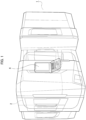
FIG. 1 is a perspective view of an external appearance of a machine tool according to an embodiment. -
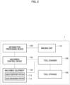
FIG. 2 is a diagram of a hardware configuration of the machine tool. -
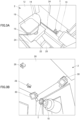
FIGS. 3A and 3B are perspective views of structures inside a machining chamber. -
FIG. 4 is a diagram schematically illustrating a structure of a camera. -
FIG. 5 is a functional block diagram of an information processing device. -
FIG. 6 is a block diagram illustrating a configuration of a recognition unit. -
FIG. 7 is a diagram illustrating a method for correcting screen display. -
FIGS. 8A and 8B are diagrams illustrating the method for correcting screen display. -
FIGS. 9A and 9B are diagrams illustrating the method for correcting screen display. -
FIGS. 10A and 10B are diagrams illustrating the method for correcting screen display. -
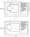
FIGS. 11A and 11B are diagrams illustrating examples of screens on which an operator performs operations. -
FIG. 12 is a flowchart illustrating a flow of a correction process. -
FIG. 13 is a flowchart schematically illustrating a flow of cleaning control. -
FIG. 14 is a diagram illustrating a configuration of an information processing system according to a modification. -
FIG. 15 is a diagram illustrating an image processing method according to a modification. - An embodiment of the present disclosure will now be described with reference to the drawings.
-
FIG. 1 is a perspective view of an external appearance of a machine tool according to an embodiment. - A
machine tool 1 is a multi-tasking machine for machining workpieces into desired shapes by appropriately changing tools. Themachine tool 1 has amachining chamber 2 inside an equipment housing. Machining equipment for machining workpieces is installed in themachining chamber 2. Aconsole 4 for operating the machining equipment is provided on a front face of the equipment housing. -
FIG. 2 is a diagram of a hardware configuration of themachine tool 1. - The
machine tool 1 includes aninformation processing device 100, amachining control device 102, themachining equipment 104, atool changer 106, atool storage 108, and animaging unit 110. Themachining control device 102 functions as a numerical control unit, and outputs control signals to themachining equipment 104 in accordance with machining programs (NC programs). Themachining equipment 104 moves a tool spindle (not illustrated; hereinafter simply referred to as a "spindle") in accordance with instructions from themachining control device 102 to machine a workpiece. - The
machining equipment 104 includes a mechanism for driving the spindle, and in addition, aliquid reservoir portion 112 for storing a coolant, and aliquid discharging portion 114 for discharging the coolant. The coolant is used as cutting fluid for removing heat from and lubricating a tool and a workpiece during machining, and also as cleaning fluid for removing chips scattered in themachining chamber 2. Theliquid discharging portion 114 includes a pump for pumping up the coolant from the liquid dischargingportion 114, a nozzle for discharging the coolant, and an actuator for driving the nozzle. - The
information processing device 100 includes theconsole 4, and outputs control commands to themachining control device 102 on the basis of operations input by an operator. Theinformation processing device 100 also controls screens displayed on a monitor of theconsole 4 in response to operations input by the operator. Thetool storage 108 stores tools. Thetool changer 106 corresponds to a so-called automatic tool changer (ATC), which takes a tool out from thetool storage 108 and replaces a tool on the spindle with the taken-out tool in accordance with a replacement instruction from themachining control device 102. - The
imaging unit 110 is a camera including an imaging sensor such as a CCD or a CMOS, for example, and images an imaging area set in themachining chamber 2. For the "imaging area", an area in which chips produced by machining of a workpiece are likely to be present is set in advance. The angle of view of the camera is set so that the distribution and accumulation of chips can be captured in a wide range in themachining chamber 2. Theimaging unit 110 outputs taken images to theinformation processing device 100. -
FIGS. 3A and 3B are perspective views of structures inside themachining chamber 2.FIG. 3A illustrates a view from obliquely above, andFIG. 3B illustrates a view from obliquely below. - As illustrated in
FIG. 3A , themachining chamber 2 is surrounded by four side faces, and aspindle 10 is installed on one of the side faces in a manner in which thespindle 10 is movable vertically and horizontally. Thespindle 10 has a rotation axis along a horizontal direction, and a tool T is coaxially attached to a distal end of thespindle 10. A side face opposite thespindle 10 in the axial direction has a revolvingdoor 12. Asupport plate 14 extends horizontally from the revolvingdoor 12. The revolvingdoor 12 is a door that is turnable about a vertical axis. - A table 16 is provided below the
support plate 14. Apallet 18 is removably attached to the table 16, and a workpiece is placed on and fixed to thepallet 18. A plurality ofpallets 18 onto each of which a workpiece is fixed are prepared, so that a workpiece can be replaced by replacement of apallet 18, which improves time efficiency. - The table 16 is movable along the axial direction of the
spindle 10, and rotatable along a horizontal plane. The table 16 is driven to rotate so as to rotate the workpiece on thepallet 18. When the table 16 is linearly driven, the workpiece moves closer to or away from the tool T. Thus, control of the rotation and the movement of the table 16 and the movement of thespindle 10 enable machining of a workpiece into a desired shape. - At a position where the table 16 is farthest from the
spindle 10, thesupport plate 14 is fitted to thepallet 18. When the revolvingdoor 12 is turned in this state, thesupport plate 14 separates thepallet 18 from the table 16 and turns with thepallet 18. In this manner, apallet 18 with a workpiece on which machining is completed can be taken out from themachining chamber 2 and apallet 18 to which a workpiece to be machined next is fixed can be brought into themachining chamber 2. - A
chip conveyor 20 for carrying chips out of themachining chamber 2 is provided below the table 16 and thespindle 10. The table 16 moves above thechip conveyor 20. Ashooter 22 is provided below the table 16. Theshooter 22 guides chips, which are flushed out from above by cleaning, onto thechip conveyor 20. - In the
machining chamber 2, bottom faces on respective sides of the table 16 are slope faces 24, which are inclined down toward theshooter 22 so that chips scattered during machining easily flow to theshooter 22. - As illustrated in
FIG. 3B , upper part of themachining chamber 2 is covered with a cover 26 (ceiling). A plurality ofnozzles 28 for supplying the coolant are provided on thecover 26. In the present embodiment, thenozzles 28 are replaceable together with thecover 26. Thenozzles 28 constitute theliquid discharging portion 114, and are connected with theliquid reservoir portion 112 via pipes, valves, pumps, and the like, which are not illustrated (seeFIG. 2 ). Thenozzles 28 are three-dimensionally rotatable. The coolant discharging direction can be controlled by rotation of thenozzles 28. The coolant can be discharged toward a target in themachining chamber 2 by specifying the directions of thenozzles 28 and driving the pumps. Chips produced during machining of workpieces are flushed out with the coolant and carried out of themachining chamber 2 by thechip conveyor 20. While twonozzles 28 are provided in the present embodiment, the number ofnozzles 28 can be set as necessary. - A plurality of
cameras 30 for imaging the inside of themachining chamber 2 from above are also provided in the upper part of themachining chamber 2. Specifically, thecameras 30 are fixed to themachine tool 1. In the present embodiment, twocameras 30 are attached to side walls at positions a little lower than thecover 26 in themachining chamber 2. In the present embodiment, thecameras 30 have structures that cannot be integrated with thecover 26 owing to wiring and other circumstances. Thecameras 30 constitute theimaging unit 110, and are configured to image the state of a workpiece being machined with a tool T and to image chips produced during machining (seeFIG. 2 ). Because twocameras 30 are provided, an area that cannot be imaged by onecamera 30 can be imaged by theother camera 30. Theimaging unit 110 outputs a taken image to theinformation processing device 100. -
FIG. 4 is a diagram schematically illustrating a structure of acamera 30. - Each
camera 30 in the present embodiment has a structure in which turning about its optical axis L is restricted. Specifically, eachcamera 30 is turnable about a yaw axis L1 perpendicular to the optical axis L and about a pitch axis L2 perpendicular to the optical axis L and to the yaw axis L1, but is not turnable about the optical axis L. Thus, in a case where the coordinates of an imaging area displayed on the screen and the coordinates of an imaging area recognized by software do not match each other owing to attachment error of acamera 30 or the like, it is difficult to manually adjust the coordinates. Thus, theinformation processing device 100 performs a correction process for eliminating the difference between the coordinates when the operator adjusts the angle of the camera. -
FIG. 5 is a functional block diagram of theinformation processing device 100. - The components of the
information processing device 100 are implemented by hardware including computing units such as central processing units (CPUs) and various computer processors, storage devices such as memories and storages, and wired or wireless communication lines that connect these units and devices, and software that is stored in the storage devices and supplies processing instructions to the computing units. Computer programs may be constituted by device drivers, operating systems, various application programs on upper layers thereof, and a library that provides common functions to these programs. The blocks explained below do not represent configurations in units of hardware but represent blocks in units of functions. - The
information processing device 100 includes a userinterface processing unit 130, adata processing unit 132, and adata storage unit 134. The userinterface processing unit 130 performs processes related to user interfaces such as receiving operations input by an operator and displaying images. Thedata processing unit 132 performs various processes on the basis of data obtained by the userinterface processing unit 130 and data stored in thedata storage unit 134. Thedata processing unit 132 also functions as an interface of the userinterface processing unit 130 and thedata storage unit 134. Thedata storage unit 134 stores various programs and set data therein. - The user
interface processing unit 130 includes an input unit 120 and anoutput unit 142. The input unit 120 receives inputs performed by the operator via the touch panel of the monitor on theconsole 4 or the like. Theoutput unit 142 includes adisplay unit 144 that displays images and the like on the screens of the monitor. Theoutput unit 142 provides a variety of information to the operator via the display. Thedisplay unit 144 displays images taken by theimaging unit 110. - The
data processing unit 132 includes anacquisition unit 150, agrid setting unit 152, adetection unit 154, arecognition unit 156, acorrection unit 158, adisplay control unit 160, and adischarge control unit 162. - The
acquisition unit 150 acquires images taken by theimaging unit 110. Thegrid setting unit 152 divides (sections) a taken image into a plurality of grid sections in order to determine (analyze) the presence of a predetermined substance (such as chips) in an imaging area. Each grid section has a specific shape (a square in the present embodiment, but any geometric shape), details of which will be described later. Hereinafter, an area that is divided into a plurality of grid sections in a taken image will also be referred to as a "grid area". In addition, an image constituted by multiple grid sections will also be referred to as a "grid image". - The
detection unit 154 detects operations input by the operator via the input unit 120. The operator can view the chip accumulation state in themachining chamber 2 by referring to a taken image displayed on thedisplay unit 144, details of which will be described later. The operator can then indicate a range for cleaning (a range for discharge) with the coolant by specifying an area in the taken image via the touch panel. Thedetection unit 154 detects the indication input by the as an indicated position on the taken image. Thedetection unit 154 may detect an indicated position based on a grid area generated by thegrid setting unit 152. - The
recognition unit 156 automatically recognizes chips on the basis of a grid area set in the taken image, determines whether or not chips are present in the grid area, and determines the volume of chips if any. These determinations will also be referred to as "chip determinations". If therecognition unit 156 has determined that chips are present in the grid area, therecognition unit 156 recognizes a position on the taken image corresponding to the grid area as a chip accumulation position. Upon recognizing the chip accumulation position, therecognition unit 156 outputs an automatic detection signal to thedischarge control unit 162. The automatic detection signal at least includes information on a predetermined position at which accumulation of chips is recognized on the taken image. - Before cleaning control is performed, the
correction unit 158 performs a correction process for making the coordinates of the imaging area of thecamera 30 and the coordinates to be used for a coolant control command match each other on the basis of an operation performed by the operator. Because this correction process is performed on the assumption that there is an attachment error of thecamera 30, this correction process is performed when thecamera 30 is installed in themachining chamber 2. Details thereof will be described later. - The
display control unit 160 causes an image taken by acamera 30 to be displayed on thedisplay unit 144. When correction is to be performed by thecorrection unit 158, thedisplay control unit 160 causes an operation screen for the correction to be displayed, and also causes the taken image resulting from the correction to be displayed. After the correction, thegrid setting unit 152 divides the taken image into grid sections. Thedisplay control unit 160 causes the corrected taken image and the grid sections superimposed on the taken image to be displayed on thedisplay unit 144. Therecognition unit 156 analyzes the presence of a target in each grid section. Examples of display screens relating to the correction will be described later in detail. - When cleaning control is to be performed, the
discharge control unit 162 outputs a command to discharge the coolant toward a target position to themachining control device 102. This discharge command includes information specifying a position to which the coolant is to be discharged (such as information specifying a discharge path). Upon receiving this discharge command, themachining control device 102 drives theliquid discharging portion 114 and controls discharge of the coolant. - The cleaning control is to flush out chips in the machining chamber 2 (that is, to clean the inside of the machining chamber 2) with the coolant, and an automated cleaning mode and a manual cleaning mode are selectable in the present embodiment. In the automated cleaning mode, the
discharge control unit 162 automatically sets a position to which the coolant is to be discharged on the basis of the automatic detection signal output from therecognition unit 156, and outputs a discharge command. In contrast, in the manual cleaning mode, thedischarge control unit 162 sets a position to which the coolant is to be discharged on the basis of specification of an area by the operator, which is detected by thedetection unit 154, and outputs a discharge command. - The
data storage unit 134 stores various programs including a correction program for performing the aforementioned correction process and a cleaning control program for performing the cleaning control, and various data necessary for the processes. Thedata storage unit 134 includes a correctioninformation storage unit 146 and a referenceinformation storage unit 148. The correctioninformation storage unit 146 stores taken images obtained by theacquisition unit 150, grid areas (grid images) generated by thegrid setting unit 152, information on a given position at which the presence of chips is recognized by therecognition unit 156 and information on the volume of chips, position information detected by thedetection unit 154, and the like in the correction process. The correctioninformation storage unit 146 also stores correction information (calibration data) obtained in the correction process, which will be described later. The referenceinformation storage unit 148 stores images for guiding the operator's input of operations in the correction process. Thedata storage unit 134 also functions as a work area in computation processes. - An outline of chip recognition by the
recognition unit 156 will now be explained. -
FIG. 6 is a block diagram illustrating a configuration of therecognition unit 156. - The
recognition unit 156 includes amodel learning unit 41, acalculation unit 43, and a determination unit 44. - The
model learning unit 41 generates a learning model. The learning model is a model capable of calculating, in response to an input of one of the grid areas generated by thegrid setting unit 152, which of predetermined items is relevant to the chips in the grid area and the probability of the relevance and outputting the calculation result. The learning model can be generated by inputting a pair of input data and output data as training data into a convolutional neural network (CNN) in advance to cause the CNN to learn the data pair, for example. In the present embodiment, a grid area can be used as input data, and information on the presence/absence and the volume of chips in the grid area can be used as output data. - The
data storage unit 134 includes amodel storage unit 42. Themodel storage unit 42 stores a learning model for automatically determining whether chips are present. The learning model is read into thecalculation unit 43 as necessary. - The
calculation unit 43 calculates the probability that chips in units of a grid area correspond to a predetermined item on the basis of a taken image. Specifically, thecalculation unit 43 uses the learning model learned by themodel learning unit 41 to calculate the probability that a grid area corresponds to each of three items, which are a "large volume of chips (class 2)", a "small volume of chips (class 1)" and "no chips (class 0)". The classes indicate the quantities of presence of materials (chips) recognized in the imaging area. - The determination unit 44 determines which of classes 0 to 2 chips in the input grid area correspond to on the basis of the probabilities calculated by the
calculation unit 43. When it is determined that chips are present in a grid area (that is, chips in a grid area corresponds toclass 2 or class 1), the determination unit 44 outputs an automatic detection signal including information on a position in a taken image corresponding to the position of the grid area in a grid image to thedisplay control unit 160 and thedischarge control unit 162. - As described above, during machining or after completion of machining of a workpiece, the
recognition unit 156 can perform automated cleaning of automatically recognizing chips on the basis of an image taken by theimaging unit 110 and discharging the coolant. The automated cleaning may be periodically performed or may be performed in response to some instruction such as an instruction from the operator. - Next, a correction method in the present embodiment will be explained in detail.
- As already described, when the cleaning control system is introduced, the coordinates of an imaging area displayed on the screen and the coordinates of an imaging area recognized by software may not match each other. Thus, in the present embodiment, before using the
machine tool 1, the operator performs operations to eliminate the difference between the coordinates such as adjusting the angle of acamera 30. For convenience of explanation, a state in which the coordinates match each other will also be referred to as a "screen matching state". - As described with reference to
FIG. 4 , because turning of thecameras 30 about their optical axes L is restricted in the present embodiment, adjustment of thecameras 30 is limited. Thus, setting error of the target of coolant discharge control may be caused. In the present embodiment, thecorrection unit 158 therefore corrects setting error of the target by turning an image taken by acamera 30. Details thereof will be explained below. -
FIGS. 7 to 10B are diagrams illustrating a method for correcting screen display. - In the present embodiment, because a plurality of
cameras 30 are provided, the correction is performed on each of thecameras 30. For convenience, an example of correction of one of thecameras 30 will be described. Theother cameras 30 are similarly corrected, and the explanation thereof is therefore omitted. - A
camera 30 is installed in themachining chamber 2 so that a predetermined imaging area is within the angle of view. The imaging area includes areas to and in which chips are expected to scatter and accumulate. Herein, assume that a taken image P0 illustrated inFIG. 7 is displayed on the screen (reference screen 170) of thedisplay unit 144 when thecamera 30 is installed in themachining chamber 2. When a maintenance mode (to be described later) for correcting the screen display is entered by an operation input by the operator, thedisplay control unit 160 causes a baseline BL (thick line) and auxiliary lines AL (one-dot chain lines) to be displayed over the taken image P0. - The baseline BL is a line set to correspond to the outline of a specific area SA in the
machining chamber 2 when the screen is in the matching state, and stored in advance in the referenceinformation storage unit 148. In the present embodiment, an area surrounded by boundaries of the slope faces 24 and the edge of thepallet 18 is the specific area SA. The auxiliary lines AL are cross auxiliary lines passing the center C of the taken image P0 in the present embodiment. In themachining chamber 2, a marker M that matches the center C when the screen is in the matching state is put. The marker M is put at a center setting position that is set in advance in the imaging area. - In the state illustrated in
FIG. 7 , the center C of the taken image P0 does not match the marker M. In addition, the outline of the specific area SA does not match the baseline BL. Thus, this screen is not in the matching state. Thus, the operator first manually adjusts the angle of thecamera 30 within a possible range so that the screen becomes closer to the matching state. - Specifically, the operator turns the
camera 30 about the yaw axis L1 and the pitch axis L2 so that the center C of the taken image P0 matches the marker M as illustrated inFIG. 8A . The adjustment so far can be easily performed manually. In the illustrated example, however, the outline of the specific area SA still does not match the baseline BL at this point. This difference between the outline and the baseline BL can be eliminated if thecamera 30 can be turned about the optical axis L, but the turning of thecamera 30 about the optical axis L is restricted in the present embodiment. - Thus, as illustrated in
FIG. 8B , thecorrection unit 158 turns the taken image P0 about the center C (that is, in the rotating direction of the optical axis L of the camera 30) so that the outline of the specific area SA matches the baseline BL. In this manner, the screen is brought into the matching state and setting error of the target of coolant discharge control is corrected. In this case, however, the taken image P0 is inclined with respect to thereference screen 170, which may result in strangeness of the screen display. - As illustrated in
FIG. 9A , a grid area GA is initially set on the basis of an ideal state in which no attachment error of thecamera 30 is present. In this ideal state, the aspect ratio (screen ratio) of the taken image P0 (see a dotted line) is 4:3 and the number of grid sections is 28×21. Thus, if the taken image P0 is turned about the optical axis, grid sections may be insufficient or excessive at the edge of the taken image P0. If some of the grid sections do not correspond with the image, the degree of accumulation of chips cannot be correctly determined. - Thus, in the grid area GA, an area (see two-dot chain line) that definitely includes the image is defined as a determination area JA, and only the determination area JA is used for chip determinations. Specifically, as illustrated in
FIG. 9B , thedisplay control unit 160 extracts an image of a specific shape by cutting the periphery of the taken image P0 after the angle of view is turned. Hereinafter, the image extracted in this process will be referred to as an "extracted image P1". In the present embodiment, the "specific shape" is assumed to be a rectangle having the same aspect ratio (4:3) as the taken image P0. Note that "cutting" used here may be deleting the periphery of the taken image P0 to leave the image corresponding to the determination area JA as data of the extracted image P1 or extracting the image corresponding to the determination area JA as data of the extracted image P1 instead of deleting the periphery. - In addition, because image processing for chip determinations is performed in units of grid sections, the
display control unit 160 cuts the periphery of the taken image P0 at least in units of either of rows and columns of the grid. In the illustrated example, the turning angle θ of the taken image P0 is three degrees, and overlapping portion of a grid image corresponding to one row of the periphery (that is one row at each of upper and lower edges and one column at each of left and right edges) and a grid image corresponding to one row of the periphery of the taken image P0 is cut off. As a result, the number of grid sections is 26×19. - If, however, the extracted image P1 is displayed in this state, the extracted image P1 is smaller than the
reference screen 170 and blank spaces are formed around it, which may appear strange. Thus, as illustrated inFIG. 10A , the extracted image P1 is enlarged to a preset size for display on thereference screen 170. Herein, the extracted image P1 is enlarged on the same scale as the original taken image P0. As a result, as illustrated inFIG. 10B , the extracted image P1 has the same size as thereference screen 170, and is displayed in a manner that the sides of the rectangular extracted image P1 are at the same positions as the sides of the rectangular original taken image P0. - Note that recognition and determination of materials (chips) by the
recognition unit 156 are performed on an initially set grid area (number of grid sections: 26×19). Because the periphery of the taken image P0 is cut off, the screen display performed by thedisplay control unit 160 may be part of the grid area. - The correction process described above enables the coordinates of the imaging area displayed on the
reference screen 170 and the coordinates of the imaging area recognized by software to match each other, and coolant to be discharged accurately toward a target position. Thus, the positions of grid sections set by thegrid setting unit 152 and the positions of grid sections that the operator recognizes in the image match each other. The position indicated on the touch panel by the operator corresponds to a grid section, and a region of the image over which the grid section is present is set as a coolant discharge position (target position). - Even when the periphery of the grid area is cut off for display as described above, the positions of the displayed grid section accurately correspond to the actual positions in the imaging area. The coolant discharge control can therefore be kept highly accurate.
-
FIGS. 11A and 11B are diagrams illustrating examples of screens on which the operator performs operations. - A
screen 200 illustrated inFIG. 11A is displayed on the monitor of theconsole 4. Thescreen 200 includes thereference screen 170 described above and anoperation screen 202 arranged next to each other. Theoperation screen 202 includes anautomated cleaning button 210, amanual cleaning button 212, a cleaningpath adjustment button 214, anddetail setting button 216. - The
automated cleaning button 210 is selected for entering the automated cleaning mode. Themanual cleaning button 212 is selected for entering the manual cleaning mode. The cleaningpath adjustment button 214 is selected for adjusting a path for cleaning with the coolant. When each of the buttons is selected, a pull-down menu allowing selection of an operation item in the corresponding cleaning mode is displayed, explanation of details of which is omitted. - When the
detail setting button 216 is selected, amaintenance button 220, an auxiliaryline display button 222, and an imageturning operation portion 224 are displayed as illustrated. When the operator selects themaintenance button 220, the maintenance mode is entered, and the baseline BL is displayed over the taken image P0. When the auxiliaryline display button 222 is turned on, the auxiliary lines AL are displayed. - The operator adjusts the yaw angle and the pitch angle of the
camera 30 by referring to thereference screen 170 so that the center C of the taken image P0 matches the marker M as described above. The turning angle θ of the taken image P0 can then be adjusted by touching on a + button or a - button of the image turningoperation portion 224. Thecorrection unit 158 causes the taken image P0 to turn 0.1 degrees clockwise each time the operator touches the + button, and causes the taken image P0 to turn 0.1 degrees counterclockwise each time the operator touches the - button. As illustrated inFIG. 11B , when the auxiliaryline display button 222 is turned off, the auxiliary lines AL are hidden. -
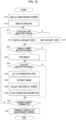
FIG. 12 is a flowchart illustrating a flow of the correction process. - This process is triggered by the operator's selecting the
maintenance button 220. - The
display control unit 160 causes the taken image P0 to be displayed on thereference screen 170 as a maintenance screen (S10), and causes the baseline BL to be displayed over the taken image P0 (S12) . - At this point, if the operator turns on the auxiliary line display button 222 (Y in S14), the
display control unit 160 causes the auxiliary lines AL to be displayed (S16). When the auxiliaryline display button 222 is off (N in S14), the auxiliary lines AL are hidden (S18). When an image turning instruction is made by operation of the image turning operation portion 224 (Y in S20), thedisplay control unit 160 turns the taken image P0 (S22). - When the outline of the specific area SA matches the baseline BL in this manner and the operator selects an enter button that is not illustrated (Y in S24), the
correction unit 158 obtains a determination area JA (S26). Specifically, an area in which the image is definitely included in the grid area GA is set as a determination area JA depending on the inclination of the taken image P0. This determination area JA functions as an "AI inferencing area" on which chip determinations are performed in units of grid sections. - The
display control unit 160 extracts the image P1 by cutting off the periphery of the taken image P0 on the basis of the determination area JA (S28), adjusts (enlarges) the extracted image P1, and displays the adjusted extracted image P1 on the reference screen 170 (S30). Thecorrection unit 158 stores the series of correction information as calibration data in the correction information storage unit 146 (S32). The correction information includes a setting angle (turning angle θ) of the taken image P0, settings of the determination area JA, an enlargement ratio (set magnification) of the extracted image P1, and the like. If the enter button is not selected (N in S24), the processing in S26 to S32 is skipped. - If a predetermined maintenance termination condition, such as the operator's selecting another button, is satisfied (Y in S34), the
display control unit 160 terminates display of the maintenance screen (S36). If the maintenance termination condition is not satisfied (N in S34), the process returns to S14. -
FIG. 13 is a flowchart schematically illustrating a flow of cleaning control. - When cleaning control is started in either of the automated cleaning mode and the manual cleaning mode, the
acquisition unit 150 obtains the taken image P0 (S40). Subsequently, thecorrection unit 158 reads the correction information (calibration data) stored in the correction information storage unit 146 (S42), and performs the correction process described above on the taken image P0 as internal processing. - Specifically, the
correction unit 158 turns the taken image P0 by a set angle (S44), sets a determination area (S46), and extracts an extracted image (S48). Subsequently, thecorrection unit 158 enlarges the extracted image with the set magnification (S50), and causes the enlarged extracted image to be displayed as the taken image on the screen (S52). Then, if an instruction to display a chip accumulation state is made by an operation input by the operator (Y in S54), thedisplay control unit 160 displays the grid image over the taken image (S56), and further displays the chip accumulation state (S58). The chip accumulation state is displayed in such a manner as in different colors depending on the classes determined by therecognition unit 156. - When the operator indicates a coolant discharge position (target) on the basis of the displayed image (Y in S60), the
detection unit 154 detects the indication. Thedischarge control unit 162 sets a coolant discharge path on the basis of the discharge position (S62), and outputs a discharge command to themachining control device 102 to discharge the coolant in accordance with the discharge path (S64). - Then, if a predetermined cleaning mode termination condition, such as the operator's selecting another button, is satisfied (Y in S66), the
display control unit 160 terminates display of the cleaning operation screen (S68). If the cleaning mode termination condition is not satisfied (N in S66), the process returns to S40. - A machine tool has been described with reference to the embodiment.
- In the present embodiment, in a case where attachment error is present in installation of a
camera 30 in themachining chamber 2, the operator can finely adjust the angle (yaw angle and pitch angle) of thecamera 30 by checking the taken image P0. Although thecamera 30 cannot be adjusted by turning (roll angle) about its optical axis, the correction can be made by turning the taken image P0. Thus, according to the present embodiment, even though the adjustment of the angle of thecamera 30 is limited in themachine tool 1, the imaging area displayed on the screen and the imaging area recognized by software can be made to match each other. Thus, even when the operator makes instructions of cleaning chips with the coolant on the basis of a taken image displayed on the screen, the cleaning instruction position and the coolant discharge position match each other. In other words, the cleaning control can be kept highly accurate. - According to the present embodiment, even though the adjustment of the angle of a
camera 30 is limited in themachine tool 1, thecorrection unit 158 performs correction, that is, turning a taken image in the rotating direction of the optical axis of the camera so that the outline of a specific area in the machine tool displayed on the taken image matches a preset line. Thegrid setting unit 152 sets a grid on the basis of the corrected taken image, and thedisplay control unit 160 causes the corrected taken image and the grid to be displayed on a display unit in such a manner that the grid is superimposed on the corrected taken image. In this manner, an imaging area displayed (in a grid) on the screen and an imaging area recognized by software can be made to match each other. Because the grid section positions set on the taken image and grid section positions that can be recognized on the image by the operator match each other, fluid can be accurately discharge toward a target in a grid section. - In addition, in the present embodiment, for correction of a taken image P0, an extracted image P1 is extracted by cutting the periphery of the taken image P0, which is inclined as a result of being turned, and the extracted image P1 is enlarged to a preset size for display. Thus, the size of the taken image can be adjusted to the screen while the outline shape of the taken image displayed on the screen is kept rectangular. As a result, the way a taken image is seen does not vary significantly depending on whether the taken image is corrected (that is, depending on individual differences of the installed cameras), and a corrected image does not appear strange to the operator.
- While the
machine tool 1 is a multi-tasking machine in the description of the embodiment, themachine tool 1 may be a turning center or a machining center. Alternatively, themachine tool 1 may be a machine for additive manufacturing in which materials (such as metal powder) are melted by laser and machined. In this case, materials scattered during machining correspond to the "substance" recognized by a material recognition unit. - In the embodiment described above, coolant is presented as an example of fluid discharged for removing chips. In a modification, the fluid may be liquid (cleaning fluid) other than coolant or gas such as air. In this case, a gas discharging portion for discharging gas is provided instead of the liquid discharging portion.
- While an example in which the turning angle θ of the taken image P0 in the correction process is three degrees has been presented in the embodiment described above (
FIG. 8B ), it is needless to say that the turning angle θ varies depending on the installation condition of acamera 30. In a case where the aspect ratio of an extracted image P1 is 4:3, the number of grid sections can be 27×20 when θ=1°, the number of grid sections can be 26×20 when θ=2°, the number of grid sections can be 25×19 when θ=4°, and the number of grid sections can be 25×18 when θ=5°, for example. - In the embodiment described above, an example in which the
information processing device 100 is an internal computer of themachine tool 1 and is integrated with theconsole 4 has been presented. The information processing device may alternatively be independent of theconsole 4. In this case, the information processing device may function as a display unit using the monitor of the console as a remote desktop. Alternatively, the information processing device may be an external computer connected with the machine tool. In this case, the information processing device may be a typical laptop personal computer (PC) or a tablet computer. -
FIG. 14 is a diagram illustrating a configuration of an information processing system according to a modification. Note that components that are similar to those in the embodiment will be designated by the same reference numerals and detailed description thereof is omitted. - In this modification, an information processing device is provided outside a machine tool. Specifically, the information processing system includes a
machine tool 301, adata processing device 310, and adata storage device 312. Thedata processing device 310 functions as the "information processing device". - The
machine tool 301 includes amachining control device 102,machining equipment 104, atool changer 106, atool storage 108, adata processing unit 330, aconsole 304, and animaging unit 110. Thedata processing unit 330 includes acommunication unit 332, agrid setting unit 152, adetection unit 154, arecognition unit 156, and adischarge control unit 162. Thecommunication unit 332 includes a reception unit and a transmission unit, and performs communication with external devices including thedata processing device 310 and thedata storage device 312. - The
console 304 includes a userinterface processing unit 130 and adata processing unit 334. Thedata processing unit 334 outputs control commands to themachining control device 102 on the basis of operations input by the operator. Thedata processing unit 334 also controls screens displayed on thedisplay unit 144 in accordance with operations input by the operator. - The
data processing device 310 includes acommunication unit 320, acorrection unit 158, and adisplay control unit 160. Thecommunication unit 320 includes a reception unit and a transmission unit, and performs communication with themachine tool 301. Thedata storage device 312 includes a correctioninformation storage unit 146 and a referenceinformation storage unit 148. While thedata storage device 312 is connected by wire in this modification, the connection may be a wireless connection. In another embodiment, thedata storage device 312 may be integrated as part of thedata processing device 310. - As described above, in this modification, the functions of the
information processing device 100 of the embodiment are separated to the inside and the outside of the machine tool. Such a configuration also produces effects similar to those of the embodiment described above. - Although not mentioned in the embodiment, the size and the shape of the grid sections may be changeable as necessary. In this case as well, an extracted image may be obtained by cutting the periphery of a taken image in units of grid sections.
- In the embodiment described above, an example in which the operator manually adjusts the angles of the
camera 30 about the yaw axis and the pitch axis to eliminate attachment error of thecamera 30 has been presented. In a modification, for controlling the angles of a camera, the information processing device may include a drive control unit to control a first turning about the yaw axis and a second turning about the pitch axis. The drive control unit controls the first turning and the second turning so that the optical axis of the camera is aligned with a preset center setting position (marker M) in the imaging area before the correction performed by the correction unit. - In the embodiment described above, an example of a configuration in which a
camera 30 cannot turn about its optical axis has been presented as a restricted state of thecamera 30. In a modification, acamera 30 may be turnable about its optical axis but the turning angle may be limited. Alternatively, acamera 30 itself may have a turnable structure but the turning may be limited to avoid interference with surrounding structures. - In the embodiment described above, as illustrated in
FIGS. 7 and8 , an example in which the center C of the taken image P0 and the optical axis L of thecamera 30 match each other and the taken image P0 is turned about the optical axis L has been presented. In a modification, a taken image may be turned regardless of the optical axis. In this case as well, the correction unit turns the taken image so that an outline of a specific area matches a baseline. Specifically, it is preferable to turn a taken image about a perpendicular axis perpendicular to the plane of the taken image and passing the center of the taken image. -
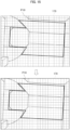
FIG. 15 is a diagram illustrating an image processing method according to a modification. - In this modification, a taken image shown in upper part of
FIG. 15 can be corrected to that shown in lower part ofFIG. 15 . Specifically, thegrid setting unit 152 performs a process (grid line division process) of overlaying grid lines on corresponding preset positions on a taken image received from theimaging unit 110. As a result of such a process, the relation between the overlaid grid lines and the taken image P10 may become as shown in the upper part ofFIG. 15 . According to the data of the overlaid grid lines and the taken image P10, among the grid sections that overlap with the taken image P10, some of outermost grid sections do not have all their four sides fully appearing on the screen. In such a case, thedisplay control unit 160 can perform a process of ignoring the grid sections that do not have all their four sides fully overlapping with the taken image and displaying only grid sections with all of their four sides fully overlapping with the taken image P10 in a size adjusted to the reference screen (lower part ofFIG. 15 ). Alternatively, thegrid setting unit 152 may perform such a process of detecting the presence of grid sections that do not have all their four sides overlapping with the taken image P10 (or grid sections that do not have all their four sides fully appearing on the screen) and performing adjustment by moving the whole mesh-like grid lines vertically and horizontally so that all the four sides overlap with the taken image P10. - The present invention is not limited to the embodiment and modifications thereof described above, and any component thereof may be modified and embodied without departing from the scope of the invention. Components described in the embodiments and modifications may be combined as appropriate to form various embodiments. Some components may be omitted from the components presented in the embodiments and modifications.
- This application claims priority to
Japanese Patent Application No. 2021-144424 filed on September 6, 2021
Claims (9)
- An information processing device that processes an image to be used for a machine tool, the machine tool taking the image of an imaging area with a camera and discharging fluid toward a target on the basis of the image, the information processing device comprising:a reference information storage unit that stores, in advance, a line that is to correspond to an outline of a specific area of the machine tool on the image when the image is displayed;a correction unit that turns the image in a rotating direction of an optical axis of the camera so that the outline of the specific area displayed on the image matches the line; anda display control unit that causes a corrected image, resulting from correction by the correction unit, to be displayed on a display unit.
- An information processing device that processes an image to be used for a machine tool, the machine tool taking the image of an imaging area with a camera and discharging fluid toward a target on the basis of information of the image, the information processing device comprising:a display control unit that controls display of a line at a specific position on a display unit, the line being to correspond to an outline of a specific area of the machine tool; anda correction unit that turns the image in a state in which the image and the line are displayed on the display unit with the line overlaid on the image, so that the outline of the specific area of the machine tool imaged in the image matches the line, whereinthe display control unit causes a corrected image, resulting from correction by the correction unit, to be displayed on the display unit.
- The information processing device according to claim 1, whereinturning of the camera about the optical axis is restricted, andthe correction unit corrects an error in setting the target by turning the image.
- The information processing device according to claim 1, further comprising:an input unit that receives operations input by an operator, whereinthe display control unit displays the line over the image before the correction by the correction unit, andthe correction unit turns the image in accordance with an operation input by the operator.
- The information processing device according to claim 4, wherein
the display control unit displays an auxiliary line passing the optical axis over the image in accordance with an operation input by the operator. - The information processing device according to claim 1, further comprising:a drive control unit for controlling angles of the camera, the drive control unit controlling a first turning about a yaw axis perpendicular to the optical axis and a second turning about a pitch axis perpendicular to the optical axis and the yaw axis, whereinthe drive control unit controls the first turning and the second turning so that the optical axis of the camera is positioned at a preset center setting position in the imaging area before the correction by the correction unit.
- The information processing device according to claim 1, wherein
the display control unit causes a rectangular image to be displayed on the display unit, the rectangular image being obtained by cutting a periphery of the image resulting from turning an angle of view. - The information processing device according to claim 1, further comprising:a grid setting unit that divides an image of the imaging area into a plurality of grid sections;a recognition unit that recognizes a predetermined substance in the imaging area in units of the grid sections on the basis of the image; anda discharge control unit that controls a discharging portion for discharging the fluid, whereinthe discharge control unit sets the target on the basis of the substance recognized in the imaging area.
- A machine tool comprising:a camera that images an imaging area set in a machining chamber;an information processing device that processes an image obtained by the imaging; anda discharging portion that discharges fluid toward a target on the basis of the processed image, whereinthe information processing device includes:a reference information storage unit that stores, in advance, a line that is to correspond to an outline of a specific area set in the machining chamber on the image when the image is displayed;a correction unit that turns the image in a rotating direction of an optical axis of the camera so that the outline of the specific area displayed on the image matches the line; anda display control unit that causes a corrected image, resulting from correction by the correction unit, to be displayed on a display unit.
Applications Claiming Priority (2)
| Application Number | Priority Date | Filing Date | Title |
|---|---|---|---|
| JP2021144424A JP7066905B1 (en) | 2021-09-06 | 2021-09-06 | Information processing equipment and machine tools |
| PCT/JP2022/031001 WO2023032662A1 (en) | 2021-09-06 | 2022-08-17 | Iinformation processing device and machine tool |
Publications (2)
| Publication Number | Publication Date |
|---|---|
| EP4393640A1 true EP4393640A1 (en) | 2024-07-03 |
| EP4393640A4 EP4393640A4 (en) | 2025-08-13 |
Family
ID=81600643
Family Applications (1)
| Application Number | Title | Priority Date | Filing Date |
|---|---|---|---|
| EP22864247.6A Pending EP4393640A4 (en) | 2021-09-06 | 2022-08-17 | I-INFORMATION PROCESSING DEVICE AND MACHINE TOOL |
Country Status (5)
| Country | Link |
|---|---|
| US (1) | US12469115B2 (en) |
| EP (1) | EP4393640A4 (en) |
| JP (1) | JP7066905B1 (en) |
| CN (1) | CN117897256A (en) |
| WO (1) | WO2023032662A1 (en) |
Families Citing this family (1)
| Publication number | Priority date | Publication date | Assignee | Title |
|---|---|---|---|---|
| JP7143053B1 (en) | 2022-06-09 | 2022-09-28 | Dmg森精機株式会社 | Information processing device and program |
Family Cites Families (13)
| Publication number | Priority date | Publication date | Assignee | Title |
|---|---|---|---|---|
| JP4640470B2 (en) | 2008-08-18 | 2011-03-02 | ソニー株式会社 | Image processing apparatus, image processing method, program, and imaging apparatus |
| JP2014099832A (en) | 2012-11-16 | 2014-05-29 | Xacti Corp | Camera |
| JP6003715B2 (en) | 2013-02-21 | 2016-10-05 | ブラザー工業株式会社 | Control device and computer program |
| JPWO2014199824A1 (en) * | 2013-06-13 | 2017-02-23 | コニカミノルタ株式会社 | Image processing method, image processing apparatus, and image processing program |
| JP6306544B2 (en) * | 2015-08-11 | 2018-04-04 | ファナック株式会社 | Machine tool cleaning system |
| US10109093B2 (en) * | 2016-05-26 | 2018-10-23 | Adobe Systems Incorporated | Automatic crop and fill boundary generation |
| JP2019030917A (en) * | 2017-08-04 | 2019-02-28 | オークマ株式会社 | Processing waste detection device and machine tool |
| JP6400817B2 (en) * | 2017-11-14 | 2018-10-03 | ファナック株式会社 | Machine tool cleaning system |
| US11113522B2 (en) * | 2018-02-08 | 2021-09-07 | Datalogic Ip Tech S.R.L. | Segment-based pattern matching algorithm |
| KR20200122658A (en) * | 2019-04-18 | 2020-10-28 | 한국기계연구원 | Workpiece-origin Self Detection Unit of Mobile Machine Tool and Method of the Same |
| JP6887033B1 (en) | 2020-02-12 | 2021-06-16 | Dmg森精機株式会社 | Image processing equipment, machine tools and image processing methods |
| JP7372181B2 (en) | 2020-03-11 | 2023-10-31 | 株式会社野村総合研究所 | computer program |
| JP6921354B1 (en) | 2021-05-24 | 2021-08-18 | Dmg森精機株式会社 | Information processing device |
-
2021
- 2021-09-06 JP JP2021144424A patent/JP7066905B1/en active Active
-
2022
- 2022-08-17 CN CN202280059787.1A patent/CN117897256A/en active Pending
- 2022-08-17 WO PCT/JP2022/031001 patent/WO2023032662A1/en not_active Ceased
- 2022-08-17 EP EP22864247.6A patent/EP4393640A4/en active Pending
-
2024
- 2024-03-04 US US18/594,937 patent/US12469115B2/en active Active
Also Published As
| Publication number | Publication date |
|---|---|
| CN117897256A (en) | 2024-04-16 |
| US12469115B2 (en) | 2025-11-11 |
| WO2023032662A1 (en) | 2023-03-09 |
| EP4393640A4 (en) | 2025-08-13 |
| US20240202890A1 (en) | 2024-06-20 |
| JP7066905B1 (en) | 2022-05-13 |
| JP2023037692A (en) | 2023-03-16 |
Similar Documents
| Publication | Publication Date | Title |
|---|---|---|
| US8988032B2 (en) | Numerical controller having display function for trajectory of tool | |
| JP5404450B2 (en) | Processing status monitoring device | |
| US7376488B2 (en) | Taught position modification device | |
| EP2082850B1 (en) | Generating device of processing robot program | |
| JP6351745B2 (en) | Machine tool control method and machine tool control apparatus | |
| US8010224B2 (en) | Automatic cutting device and production method for beveled product | |
| US20050154489A1 (en) | Numerical controller | |
| EP3689540B1 (en) | On-machine measuring method and control device of machine tool | |
| US11947332B2 (en) | CAD data-based automatic operation device of machining center | |
| KR20150117592A (en) | Teaching system, robot system, and teaching method | |
| US12469115B2 (en) | Information processing device and machine tool | |
| EP4330778B1 (en) | Information processing device | |
| JPH11320145A (en) | Three-dimensional laser processing machine, and control method for compiling processing program in three-dimensional laser processing machine | |
| EP3511120B1 (en) | Machine tool provided with display device | |
| KR102752098B1 (en) | Milling machine and control apparatus for milling machine | |
| JP5985087B1 (en) | Numerical controller | |
| KR20220157826A (en) | the method for successively efficiently processing the cut sub-process of the multi-phase of the improvement processing using the image sensor | |
| JP3958815B2 (en) | Tool position measuring method in NC machine tools | |
| JP7405899B2 (en) | Information processing equipment and machine tools | |
| JP2011158981A (en) | Working situation monitoring device | |
| JP7551164B2 (en) | Image teaching method and image teaching system | |
| WO2023032876A1 (en) | Information processing device, and machine tool | |
| WO2020065854A1 (en) | Workpiece position detecting method and machine tool | |
| JPH07205014A (en) | Grinding robot | |
| WO2022170572A1 (en) | Method and apparatus for tuning robot path for processing workpiece |
Legal Events
| Date | Code | Title | Description |
|---|---|---|---|
| STAA | Information on the status of an ep patent application or granted ep patent |
Free format text: STATUS: THE INTERNATIONAL PUBLICATION HAS BEEN MADE |
|
| PUAI | Public reference made under article 153(3) epc to a published international application that has entered the european phase |
Free format text: ORIGINAL CODE: 0009012 |
|
| STAA | Information on the status of an ep patent application or granted ep patent |
Free format text: STATUS: REQUEST FOR EXAMINATION WAS MADE |
|
| 17P | Request for examination filed |
Effective date: 20240325 |
|
| AK | Designated contracting states |
Kind code of ref document: A1 Designated state(s): AL AT BE BG CH CY CZ DE DK EE ES FI FR GB GR HR HU IE IS IT LI LT LU LV MC MK MT NL NO PL PT RO RS SE SI SK SM TR |
|
| DAV | Request for validation of the european patent (deleted) | ||
| DAX | Request for extension of the european patent (deleted) | ||
| A4 | Supplementary search report drawn up and despatched |
Effective date: 20250711 |
|
| RIC1 | Information provided on ipc code assigned before grant |
Ipc: B23Q 17/24 20060101AFI20250707BHEP Ipc: B23Q 11/00 20060101ALI20250707BHEP Ipc: B23Q 17/00 20060101ALI20250707BHEP |