EP4393579A1 - Granulating apparatus for producing granules by agglomeration - Google Patents
Granulating apparatus for producing granules by agglomeration Download PDFInfo
- Publication number
- EP4393579A1 EP4393579A1 EP23218763.3A EP23218763A EP4393579A1 EP 4393579 A1 EP4393579 A1 EP 4393579A1 EP 23218763 A EP23218763 A EP 23218763A EP 4393579 A1 EP4393579 A1 EP 4393579A1
- Authority
- EP
- European Patent Office
- Prior art keywords
- wall
- drum
- granulating
- granulating apparatus
- support structure
- Prior art date
- Legal status (The legal status is an assumption and is not a legal conclusion. Google has not performed a legal analysis and makes no representation as to the accuracy of the status listed.)
- Pending
Links
- 238000005054 agglomeration Methods 0.000 title claims abstract description 12
- 230000002776 aggregation Effects 0.000 title claims abstract description 12
- 239000008187 granular material Substances 0.000 title claims abstract description 10
- 238000004140 cleaning Methods 0.000 claims abstract description 17
- 239000012254 powdered material Substances 0.000 claims abstract description 9
- 239000006185 dispersion Substances 0.000 claims description 15
- 239000012530 fluid Substances 0.000 claims description 14
- 239000000463 material Substances 0.000 claims description 10
- 239000000843 powder Substances 0.000 claims description 8
- 238000007689 inspection Methods 0.000 claims description 2
- 230000000284 resting effect Effects 0.000 claims description 2
- 238000012423 maintenance Methods 0.000 description 8
- 239000000919 ceramic Substances 0.000 description 7
- 230000003179 granulation Effects 0.000 description 5
- 238000005469 granulation Methods 0.000 description 5
- 239000000203 mixture Substances 0.000 description 4
- 238000003756 stirring Methods 0.000 description 4
- 230000015572 biosynthetic process Effects 0.000 description 2
- 238000013016 damping Methods 0.000 description 2
- 239000003337 fertilizer Substances 0.000 description 2
- 238000004519 manufacturing process Methods 0.000 description 2
- XLYOFNOQVPJJNP-UHFFFAOYSA-N water Substances O XLYOFNOQVPJJNP-UHFFFAOYSA-N 0.000 description 2
- 206010039509 Scab Diseases 0.000 description 1
- 238000007792 addition Methods 0.000 description 1
- 230000005484 gravity Effects 0.000 description 1
- 238000012856 packing Methods 0.000 description 1
- 239000002994 raw material Substances 0.000 description 1
- 238000007790 scraping Methods 0.000 description 1
- 238000007789 sealing Methods 0.000 description 1
- 238000005507 spraying Methods 0.000 description 1
- 239000011882 ultra-fine particle Substances 0.000 description 1
Images

Classifications
-
- B—PERFORMING OPERATIONS; TRANSPORTING
- B01—PHYSICAL OR CHEMICAL PROCESSES OR APPARATUS IN GENERAL
- B01J—CHEMICAL OR PHYSICAL PROCESSES, e.g. CATALYSIS OR COLLOID CHEMISTRY; THEIR RELEVANT APPARATUS
- B01J2/00—Processes or devices for granulating materials, e.g. fertilisers in general; Rendering particulate materials free flowing in general, e.g. making them hydrophobic
- B01J2/12—Processes or devices for granulating materials, e.g. fertilisers in general; Rendering particulate materials free flowing in general, e.g. making them hydrophobic in rotating drums
Definitions
- the space inside the granulation chamber is rather narrow. Therefore, the operator finds it very difficult to move within the chamber, exposing the operator to potential accidents and therefore extending the times required for the cleaning and maintenance operations, and, as a result, machine downtime.
- An object of the present invention is to improve the current granulating apparatuses for the agglomeration of granules.
- An advantage of the invention lies in reducing machine downtime due to the cleaning and maintenance operations of the granulating chamber and of the components enclosed therein, of a granulating apparatus.
- a granulating apparatus 10 for producing granules by agglomeration of powdered material, in particular for producing ceramic microgranules used for forming ceramic tiles.
- the second wall 14 is arranged at a second end 12" of the drum and it is fixed with respect to the rotation of the drum 12; differently, the first wall 13 is movable along the aforementioned horizontal axis X, with respect to the drum 12, between a working position PL and a cleaning position PP.
- the first wall 13 is arranged, fixedly with respect to the rotation of the drum 12, at a first end 12' of the drum 12; in this position, the first wall 13, the drum 12 and the second wall 14 define a granulating chamber 11.
- the granulating apparatus 10 also comprises a dispersing assembly 24, which is provided with a dispersion bar element 30 and with a dispersion motor 28 suitable to drive the dispersion bar element 30 in rotation.
- the dispersion bar element 30 is driven in rotation around a rotation axis X' substantially parallel to the horizontal axis X.
- the dispersing assembly 24 comprises at least one stirring fin 17, that is at least one element which projects radially with respect to the rotation axis X' of the dispersion bar element 30.
- the at least one stirring fin 17 may for example be a stirring spatula and/or a stirring blade.
- the first wall 13 is an entrance wall: that is, the first wall 13 is provided with an inlet opening 26, obtained thereon, for the powder material, for example a mixture of low moisture content powder ceramic raw materials.
- the first wall 13 is traversed by the dispersion bar element 30.
- a packing ensures the sealing between the drum 12 and the first wall 13.
- the second wall 14 is an outlet wall: that is, the second wall 14 is provided with an outlet opening 27 for the agglomerated material. Furthermore, the second wall 14 has an inspection opening 31 suitable to allow an operator to visually check the granulating chamber 11 from the exterior.
- the granulating apparatus 10 further comprises a support structure 15 in contact with, and fixed with reference to, a resting surface S on which the granulating apparatus 10 is arranged in use.
- the second wall 14 and the drum 12 are mounted on said support structure 15.
- the support structure 15 supports a movement unit 16 ( Fig.2 ) arranged so as to slide the first wall 13 and the dispersing assembly 24 on the support structure 15 along the horizontal axis X.
- the movement unit 16 comprises a frame 18, to which the first wall 13 and the dispersing assembly 24 are fixed, and an actuator 23 suitable to move the frame 18 along guides 20 positioned on the support structure 15 and parallel to the horizontal axis X.
- the frame 18, in particular, is provided with slides 19 for the sliding along the aforementioned guides 20.
- the actuator 23 is chosen from a group comprising electrical linear cylinders and pneumatic linear cylinders.
- the actuator 23 is a linear cylinder parallel to the horizontal axis X.
- the linear cylinder has a movable part 21 coupled to the frame 18 and a fixed part 22 connected to the support structure 15.
- the stroke of the movable part 21 of the linear cylinder is such that there are defined two end positions of the frame 18 along the guides 20.
- the two end positions respectively correspond to the working position PL and to the cleaning position PP of the first wall 13.
- the frame 18 comprises fixing elements 29, couplable with the support structure 15, to fix the frame 18 in the end position corresponding to the working position PL.
- the fixing elements 29 are of the lever and hook type.
- each of the fixing elements 29 has an end of the lever which is hinged to the frame 18 and a free end which projects towards the support structure 15, on which the hook is arranged. In this manner, upon engaging the free ends of the levers to the respective hooks, each lever is tensioned therefore fixing the frame 18 with respect to the support structure 15.
- the granulating apparatus 10 also comprise a fluid dispensing element 25 arranged to dispense a fluid, for example by spraying, on the powdered material; the fluid dispenser is assembled on the first wall 13. Therefore, by moving the first wall 13, the movement unit 16 also slides the fluid dispensing element 25 parallel to the horizontal axis X.
- the fluid dispensing element 25 is positioned, in particular, above the inlet opening 26 and may include, for example, nozzles (not shown) supplied by one or more ducts and configured to dispense a wet mixture, for example water or slip, inside the granulating chamber 11.
- the nozzles may dispense the wet mixture simultaneously or they may be suitable to be activated selectively.
- the granulating apparatus 10 is provided with a scraper 45, shown in Figs.4 and 5 , suitable for scraping the interior of the granulating chamber 11.
- the granulating apparatus 10 includes damping elements (not shown) for damping the vibrations produced during the rotation of the drum 12 and of the dispersion bar element 30.
- the fixing elements 29 allow the frame 18 to remain in position despite the vibrations due to the rotation of the various components of the granulating apparatus 10.
- the drum 12 is driven in rotation around the horizontal axis X, for example at a speed comprised between 5 and 25 revolutions/min, the powdered material to be agglomerated is supplied to the granulating chamber 11 through the inlet opening 26 and the fluid dispensing element 25 dispenses the wet mixture.
- the rotation of the drum 12 induces the powdered material to roll on itself, this allowing the formation of agglomerates and, in particular, allowing the mixing of the powdered material contained in the granulating chamber 11.
- the powdered material introduced into the granulating chamber 11 tends to accumulate in the lower part thereof forming a powder bed; however, it is clear that the structure of the powder bed is strictly related to the rotation direction (clockwise or anticlockwise) of the drum 12.
- the dispersion bar element 30 is driven in rotation according to a direction opposite to the one of the drum 12.
- the dispersion bar element 30 has two functions: as a matter of fact, besides dispersing the ultra-fine particles so as to facilitate the agglomeration thereof, it also crushes the larger agglomerates so as to limit the size thereof above.
- the rotation of the dispersion bar element 30 is set so that the material is not projected against the fluid dispensing element 25 so as to reduce the risk of formation of crusts on the fluid dispensing element 25 which would affect the operation thereof.
- the agglomerated material After entirely traversing the granulating chamber 11, the agglomerated material is discharged through the outlet opening 27.
- the fixing elements 29 are decoupled from the support structure 15 and the actuator 23 slides the frame 18 along the guides 20 from the end position corresponding to the working position PL until the end position corresponding to the cleaning position PP is reached, therefore making the granulation chamber 11 accessible.
- the actuator 23 slides the frame 18 along the guides 20 in the opposite direction, that is from the end position corresponding to the cleaning position PP to the end position corresponding to the working position PL, and the fixing elements 29 are once again coupled to the support structure 15. At this point, the granulating apparatus 10 is ready to resume operating.
- the granulating apparatus 10 attains all intended objects by overcoming the drawbacks of the prior art.
- the granulating apparatus allows an operator to access into the granulating chamber quickly, comfortably, and safely.
- the present invention may be applied in the ceramic industry, as well as in other industries such as for example in the production of fertilizers, pet-food, et cetera.
Landscapes
- Chemical & Material Sciences (AREA)
- Organic Chemistry (AREA)
- Chemical Kinetics & Catalysis (AREA)
- Glanulating (AREA)
Abstract
A granulating apparatus (10) for producing granules by agglomeration of powdered material comprises a drum (12) which extends along, and which can be driven in rotation around, a horizontal axis (X), a first wall (13) and a second wall (14); the second wall (14) is arranged at a second end (12") of the drum (12) and it is fixed with respect to the rotation of the drum (12), the first wall (13), on the contrary, is movable along the horizontal axis (X), with respect to the drum (12), between a working position (PL), in which the drum (12), the first wall (13) and the second wall (14) define a granulating chamber (11), and a cleaning position (PP), in which the first wall (13) is far from the drum (12), therefore allowing access to the interior of the granulating chamber (11).
Description
- The present invention relates to a granulating apparatus for producing granules by agglomeration of powder material, in particular for producing ceramic microgranules used for forming ceramic tiles. The present invention may be applied both in the ceramic industry and in other industries such as, for example, in the production of fertilizers, pet-food, et cetera.
- Granulating apparatuses for the agglomeration of granules comprising a granulating chamber that is cylindrical-shaped and rotatable around its longitudinal axis, inside which there is provided a dispersing element which rotates in the same direction as the granulating chamber or in the opposite direction, are known.
- In particular, the material is introduced into the granulating chamber driven in rotation before receiving a fluid, such as water or slip, from a fluid dispensing element; the combination of dispersing element and fluid dispensing element allows to obtain an agglomeration limiting the maximum size of the microgranules.
- In such known apparatuses, the granulation chamber is closed and, therefore, they are provided with a hatch, obtained on the granulation chamber, so as to allow an operator to access thereinto to perform the cleaning and maintenance operations.
- However, the apparatuses of the type described above reveal some drawbacks known to the person skilled in the art.
- First of all, the hatches are small and therefore access thereto is very uncomfortable and, at the same time, the size of the operator designated to perform cleaning and/or maintenance operations of the granulating chamber, and of the components enclosed therein, must be compatible with that of the hatch.
- Furthermore, the space inside the granulation chamber is rather narrow. Therefore, the operator finds it very difficult to move within the chamber, exposing the operator to potential accidents and therefore extending the times required for the cleaning and maintenance operations, and, as a result, machine downtime.
- Therefore, it is advisable to provide a granulating apparatus for the agglomeration of granules which allows an operator to access into the granulating chamber quickly, comfortably, and safely so as to quicken the granulating chamber maintenance and/or cleaning operations.
- An object of the present invention is to improve the current granulating apparatuses for the agglomeration of granules.
- In particular, it is desired to provide a granulating apparatus for producing granules by agglomeration of powdered material, which allows an operator to access into the granulation chamber quickly, comfortably, and safely.
- An advantage of the invention lies in reducing machine downtime due to the cleaning and maintenance operations of the granulating chamber and of the components enclosed therein, of a granulating apparatus.
- The objects and advantages listed above and still others are attained by means of a granulating apparatus for the agglomeration of granules as defined in the attached claims.
- The invention will be better understood and implemented with reference to the attached drawings which show an exemplifying and non-limiting embodiment thereof, wherein:
-
Fig.1 is a lateral view of a granulating apparatus according to the invention in a first position; -
Fig.2 is a top view of the granulating apparatus ofFig. 1 ; -
Fig.3 is a front view of the granulating apparatus ofFig.1 ; -
Fig.4 is a longitudinal cross-section of the granulating apparatus ofFig.1 ; -
Fig.5 is a lateral view of the granulating apparatus ofFig.1 in a second position. - The general characteristics of the present invention will be shown below through the exemplifying and non-limiting embodiment of the attached figures.
- With reference to the attached figures, disclosed below is a
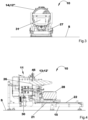
granulating apparatus 10 for producing granules by agglomeration of powdered material, in particular for producing ceramic microgranules used for forming ceramic tiles. - The
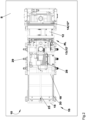
granulating apparatus 10 comprises adrum 12, which extends along a horizontal axis X and can be driven in rotation therearound, afirst wall 13 and asecond wall 14. In the embodiment of the attached figures, thedrum 12 is a hollow cylinder whose symmetry axis coincides with the horizontal axis X, while thefirst wall 13 and thesecond wall 14 substantially have a cylindrical symmetry around the aforementioned horizontal axis X. - In particular, the
second wall 14 is arranged at asecond end 12" of the drum and it is fixed with respect to the rotation of thedrum 12; differently, thefirst wall 13 is movable along the aforementioned horizontal axis X, with respect to thedrum 12, between a working position PL and a cleaning position PP. - As shown in
Fig.1 , in the aforementioned working position PL, thefirst wall 13 is arranged, fixedly with respect to the rotation of thedrum 12, at a first end 12' of thedrum 12; in this position, thefirst wall 13, thedrum 12 and thesecond wall 14 define agranulating chamber 11. - On the contrary, with reference to
Fig.5 , in the cleaning position PP, thefirst wall 13 is far from thedrum 12, therefore allowing access into thegranulating chamber 11. - Still with reference to
Fig.5 , thegranulating apparatus 10 also comprises adispersing assembly 24, which is provided with adispersion bar element 30 and with adispersion motor 28 suitable to drive thedispersion bar element 30 in rotation. In particular, thedispersion bar element 30 is driven in rotation around a rotation axis X' substantially parallel to the horizontal axis X. - Furthermore, the
dispersing assembly 24 comprises at least one stirringfin 17, that is at least one element which projects radially with respect to the rotation axis X' of thedispersion bar element 30. The at least one stirringfin 17 may for example be a stirring spatula and/or a stirring blade. - As shown in
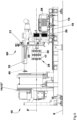
Figs.4 and5 , thefirst wall 13 is an entrance wall: that is, thefirst wall 13 is provided with an inlet opening 26, obtained thereon, for the powder material, for example a mixture of low moisture content powder ceramic raw materials. Thefirst wall 13 is traversed by thedispersion bar element 30. A packing ensures the sealing between thedrum 12 and thefirst wall 13. - On the contrary, the
second wall 14, with reference toFig.3 , is an outlet wall: that is, thesecond wall 14 is provided with an outlet opening 27 for the agglomerated material. Furthermore, thesecond wall 14 has an inspection opening 31 suitable to allow an operator to visually check the granulatingchamber 11 from the exterior. - With reference to
Figs.1 ,2 ,4 and5 , thegranulating apparatus 10 further comprises asupport structure 15 in contact with, and fixed with reference to, a resting surface S on which thegranulating apparatus 10 is arranged in use. - The
second wall 14 and thedrum 12 are mounted on saidsupport structure 15. In addition, thesupport structure 15 supports a movement unit 16 (Fig.2 ) arranged so as to slide thefirst wall 13 and thedispersing assembly 24 on thesupport structure 15 along the horizontal axis X. - In detail, the
movement unit 16 comprises aframe 18, to which thefirst wall 13 and thedispersing assembly 24 are fixed, and anactuator 23 suitable to move theframe 18 alongguides 20 positioned on thesupport structure 15 and parallel to the horizontal axis X. Theframe 18, in particular, is provided withslides 19 for the sliding along theaforementioned guides 20. - The
actuator 23 is chosen from a group comprising electrical linear cylinders and pneumatic linear cylinders. - In the exemplifying embodiment of the attached figures, the
actuator 23 is a linear cylinder parallel to the horizontal axis X. In particular, the linear cylinder has amovable part 21 coupled to theframe 18 and afixed part 22 connected to thesupport structure 15. - The stroke of the
movable part 21 of the linear cylinder is such that there are defined two end positions of theframe 18 along theguides 20. - The two end positions respectively correspond to the working position PL and to the cleaning position PP of the
first wall 13. In particular, theframe 18 comprisesfixing elements 29, couplable with thesupport structure 15, to fix theframe 18 in the end position corresponding to the working position PL. - In the embodiment of the attached figures, the
fixing elements 29 are of the lever and hook type. In particular, each of thefixing elements 29 has an end of the lever which is hinged to theframe 18 and a free end which projects towards thesupport structure 15, on which the hook is arranged. In this manner, upon engaging the free ends of the levers to the respective hooks, each lever is tensioned therefore fixing theframe 18 with respect to thesupport structure 15. - As shown in
Fig.5 , thegranulating apparatus 10 also comprise a fluid dispensingelement 25 arranged to dispense a fluid, for example by spraying, on the powdered material; the fluid dispenser is assembled on thefirst wall 13. Therefore, by moving thefirst wall 13, themovement unit 16 also slides the fluid dispensingelement 25 parallel to the horizontal axis X. - The fluid dispensing
element 25 is positioned, in particular, above the inlet opening 26 and may include, for example, nozzles (not shown) supplied by one or more ducts and configured to dispense a wet mixture, for example water or slip, inside the granulatingchamber 11. In detail, the nozzles may dispense the wet mixture simultaneously or they may be suitable to be activated selectively. - Furthermore, the
granulating apparatus 10 is provided with ascraper 45, shown inFigs.4 and5 , suitable for scraping the interior of thegranulating chamber 11. - Lastly, the
granulating apparatus 10 includes damping elements (not shown) for damping the vibrations produced during the rotation of thedrum 12 and of thedispersion bar element 30. - Briefly described hereinafter is the working of the granulating
apparatus 10 and the operation for moving thefirst wall 13 from the working position PL to the cleaning position PP (and vice versa). - Therefore, let us consider the configuration in which the
first wall 13 is located in the aforementioned working position PL and thefixing elements 29 are coupled to thesupport structure 15 so as to ensure the correct positioning of theframe 18 during working of thegranulating apparatus 10. In particular, thefixing elements 29 allow theframe 18 to remain in position despite the vibrations due to the rotation of the various components of thegranulating apparatus 10. - In this configuration, the
drum 12 is driven in rotation around the horizontal axis X, for example at a speed comprised between 5 and 25 revolutions/min, the powdered material to be agglomerated is supplied to thegranulating chamber 11 through theinlet opening 26 and thefluid dispensing element 25 dispenses the wet mixture. - The rotation of the
drum 12 induces the powdered material to roll on itself, this allowing the formation of agglomerates and, in particular, allowing the mixing of the powdered material contained in thegranulating chamber 11. - Due to the force of gravity, the powdered material introduced into the granulating
chamber 11 tends to accumulate in the lower part thereof forming a powder bed; however, it is clear that the structure of the powder bed is strictly related to the rotation direction (clockwise or anticlockwise) of thedrum 12. - In the meantime, the
dispersion bar element 30 is driven in rotation according to a direction opposite to the one of thedrum 12. In particular, thedispersion bar element 30 has two functions: as a matter of fact, besides dispersing the ultra-fine particles so as to facilitate the agglomeration thereof, it also crushes the larger agglomerates so as to limit the size thereof above. - Furthermore, the rotation of the
dispersion bar element 30 is set so that the material is not projected against thefluid dispensing element 25 so as to reduce the risk of formation of crusts on thefluid dispensing element 25 which would affect the operation thereof. - After entirely traversing the granulating
chamber 11, the agglomerated material is discharged through theoutlet opening 27. - Whenever there arises the need to perform the cleaning and/or maintenance operations of the granulating
chamber 11, and of the components enclosed therein, the rotation of thedrum 12 and of thedispersion bar element 30 is stopped and the supply of powder material to be agglomerated is interrupted. - Subsequently, the fixing
elements 29 are decoupled from thesupport structure 15 and theactuator 23 slides theframe 18 along theguides 20 from the end position corresponding to the working position PL until the end position corresponding to the cleaning position PP is reached, therefore making thegranulation chamber 11 accessible. - Once through with the cleaning and/or maintenance operations required, the
actuator 23 slides theframe 18 along theguides 20 in the opposite direction, that is from the end position corresponding to the cleaning position PP to the end position corresponding to the working position PL, and the fixingelements 29 are once again coupled to thesupport structure 15. At this point, thegranulating apparatus 10 is ready to resume operating. - In the light of the above, the
granulating apparatus 10 attains all intended objects by overcoming the drawbacks of the prior art. - In particular, the granulating apparatus according to the present invention allows an operator to access into the granulating chamber quickly, comfortably, and safely.
- Therefore, owing to the present invention, machine downtime due to the cleaning and maintenance operations of a granulating apparatus are reduced, thus increasing the efficiency of the system.
- The present invention may be applied in the ceramic industry, as well as in other industries such as for example in the production of fertilizers, pet-food, et cetera.
- Variants and/or additions to what is disclosed above and illustrated in the attached drawings are possible.
Claims (10)
- Granulating apparatus (10) for producing granules by agglomeration of powder material comprising a drum (12) extending along a horizontal axis (X) and actuatable in rotation around said horizontal axis (X), a first wall (13) and a second wall (14), said second wall (14) being arranged at a second end (12") of said drum (12) and being fixed with respect to the rotation of said drum (12), characterised in that said first wall (13) is movable along said horizontal axis (X), with respect to said drum (12), between a working position (PL), in which said first wall (13) is arranged, in a fixed manner with respect to the rotation of said drum (12), at a first end (12') of said drum (12), said first wall (13), said drum (12) and said second wall (14) thus defining a granulating chamber (11), and a cleaning position (PP), in which said first wall (13) is far from said drum (12), thus allowing access into said granulating chamber (11).
- Granulating apparatus (10) according to claim 1, wherein said first wall (13) is an entrance wall provided with an inlet opening (26) for the entry of said powdered material into said granulating chamber (11), and wherein said second wall (14) is an outlet wall provided with an outlet opening (27) for the exit of agglomerated material from said granulating chamber (11).
- Granulating apparatus (10) according to claim 1 or 2, and further comprising a dispersing assembly (24) provided with a dispersion bar element (30) and with a dispersion motor (28) suitable for driving said dispersion bar element (30) in rotation, wherein said first wall (13) is traversed by said dispersion bar element (30).
- Granulating apparatus (10) according to the preceding claim, comprising a support structure (15) in contact with, and fixed with respect to, a resting surface (S) on which, in use, said granulating apparatus (10) is arranged, said second wall (14) and said drum (12) being mounted on said support structure (15), and wherein said support structure (15) supports a movement unit (16) arranged so as to slide said first wall (13) and said dispersing assembly (24) on said support structure (15) parallel to said horizontal axis (X).
- Granulating apparatus (10) according to the preceding claim, wherein said movement unit (16) comprises a frame (18), to which said first wall (13) and said dispersing assembly (24) are fixed, and further comprising an actuator (23) suitable to move said frame (18) along guides (20) positioned on said support structure (15) and parallel to said horizontal axis (X), said frame (18) further being provided with slides (19) for sliding along said guides (20).
- Granulating apparatus (10) according to the preceding claim, wherein said actuator (23) is chosen from a group comprising electrical linear cylinders and pneumatic linear cylinders, said actuator (23) being parallel to said horizontal axis (X).
- Granulating apparatus (10) according to the preceding claim, wherein said actuator (23) has a movable part (21) coupled to said frame (18) and a fixed part (22) connected to said support structure (15), and wherein the stroke of said movable part (21) of said actuator (23) is such as to define two end positions of said frame (18) along said guides (20), said two end positions respectively corresponding to said working position (PL) and to said cleaning position (PP).
- Granulating apparatus (10) according to the preceding claim, wherein said frame (18) comprises fixing elements (29), couplable with said support structure (15), to fix said frame (18) in said end position corresponding to said working position (PL).
- Granulating apparatus (10) according to any one of the preceding claims, comprising a fluid dispensing element (25) arranged to dispense fluid on said powder material, said fluid dispensing element (25) being fitted to said first wall (13).
- Granulating apparatus (10) according to any one of the preceding claims, wherein said second wall (14) has an inspection opening (31) suitable for enabling an operator to visually check said granulating chamber (11) from the exterior.
Applications Claiming Priority (1)
| Application Number | Priority Date | Filing Date | Title |
|---|---|---|---|
| IT102022000027354A IT202200027354A1 (en) | 2022-12-30 | 2022-12-30 | Granulator apparatus for producing granules by agglomeration |
Publications (1)
| Publication Number | Publication Date |
|---|---|
| EP4393579A1 true EP4393579A1 (en) | 2024-07-03 |
Family
ID=85685738
Family Applications (1)
| Application Number | Title | Priority Date | Filing Date |
|---|---|---|---|
| EP23218763.3A Pending EP4393579A1 (en) | 2022-12-30 | 2023-12-20 | Granulating apparatus for producing granules by agglomeration |
Country Status (3)
| Country | Link |
|---|---|
| EP (1) | EP4393579A1 (en) |
| CN (1) | CN118267923A (en) |
| IT (1) | IT202200027354A1 (en) |
Citations (3)
| Publication number | Priority date | Publication date | Assignee | Title |
|---|---|---|---|---|
| DE4005207A1 (en) * | 1990-02-20 | 1991-08-22 | Loedige Maschbau Gmbh Geb | DEVICE FOR FILM PAINTING AND / OR SUGAR PAINTING |
| US20010013314A1 (en) * | 2000-02-16 | 2001-08-16 | Ets. F. Dumoulin Et Cie | Installation for the sugarcoating or encasing of products with a device for cleaning the distribution or proportioning manifold |
| US10702881B2 (en) * | 2017-04-26 | 2020-07-07 | Robert Bosch Gmbh | Coating apparatus and coating method for granular bodies |
-
2022
- 2022-12-30 IT IT102022000027354A patent/IT202200027354A1/en unknown
-
2023
- 2023-12-20 EP EP23218763.3A patent/EP4393579A1/en active Pending
- 2023-12-28 CN CN202311836524.XA patent/CN118267923A/en active Pending
Patent Citations (3)
| Publication number | Priority date | Publication date | Assignee | Title |
|---|---|---|---|---|
| DE4005207A1 (en) * | 1990-02-20 | 1991-08-22 | Loedige Maschbau Gmbh Geb | DEVICE FOR FILM PAINTING AND / OR SUGAR PAINTING |
| US20010013314A1 (en) * | 2000-02-16 | 2001-08-16 | Ets. F. Dumoulin Et Cie | Installation for the sugarcoating or encasing of products with a device for cleaning the distribution or proportioning manifold |
| US10702881B2 (en) * | 2017-04-26 | 2020-07-07 | Robert Bosch Gmbh | Coating apparatus and coating method for granular bodies |
Also Published As
| Publication number | Publication date |
|---|---|
| CN118267923A (en) | 2024-07-02 |
| IT202200027354A1 (en) | 2024-06-30 |
Similar Documents
| Publication | Publication Date | Title |
|---|---|---|
| CN106457691B (en) | Coating apparatus combination unit for 3D printer and method of applying two layers of granular build material | |
| KR20180119568A (en) | Mixers, systems for applying building materials and methods for producing buildings from building materials | |
| DE2337129A1 (en) | DEVICE FOR PREPARING AND DISPENSING FIBER-CONCRETE MIXTURES | |
| DE3131808A1 (en) | DEVICE FOR COATING GRANULES LIKE DRAGE CORES WITH A COVER AND FOR DRYING THIS COVER | |
| EP4393579A1 (en) | Granulating apparatus for producing granules by agglomeration | |
| JPH10309452A (en) | Powder and grain precision processing device | |
| EP4393580A1 (en) | Granulating apparatus for producing granules by agglomeration | |
| EP0673735B1 (en) | Apparatus with cylinders arranged opposite each other for actuating the rod of a presser element in mixing machines of the internal type | |
| US3848810A (en) | Concrete-displacement apparatus | |
| US2551984A (en) | Mixer | |
| US2838290A (en) | Material conditioner | |
| KR20040015395A (en) | A sand mixing device | |
| BR102023027733A2 (en) | GRANULATION APPARATUS | |
| US3969053A (en) | Device for distributing dyestuffs or other additional materials in extruders or the like | |
| BR102023027751A2 (en) | GRANULATION APPARATUS | |
| DE2108181B2 (en) | Device for processing, mixing, loosening, dividing or cooling of granular material, in particular casting sand | |
| EP0775651A2 (en) | Pneumatic tube conveyor system | |
| DE1507894A1 (en) | Mixer for bulk goods | |
| DE3833529A1 (en) | Apparatus for mixing solid materials | |
| RU2286843C1 (en) | Mixer for powders | |
| JP5203013B2 (en) | Concrete pump | |
| KR20000031024A (en) | Grease sprayer of wire rope | |
| ITSV960033A1 (en) | DUST SPREADER MACHINE WITH AN OSCILLATING BRUSH DEVICE. | |
| DE590573C (en) | Locking device for blow molding machines | |
| DE2740914C3 (en) | Machine for the pneumatic conveying of a dry mix in the form of shotcrete or the like. to a spray device |
Legal Events
| Date | Code | Title | Description |
|---|---|---|---|
| PUAI | Public reference made under article 153(3) epc to a published international application that has entered the european phase |
Free format text: ORIGINAL CODE: 0009012 |
|
| STAA | Information on the status of an ep patent application or granted ep patent |
Free format text: STATUS: THE APPLICATION HAS BEEN PUBLISHED |
|
| AK | Designated contracting states |
Kind code of ref document: A1 Designated state(s): AL AT BE BG CH CY CZ DE DK EE ES FI FR GB GR HR HU IE IS IT LI LT LU LV MC ME MK MT NL NO PL PT RO RS SE SI SK SM TR |
|
| STAA | Information on the status of an ep patent application or granted ep patent |
Free format text: STATUS: REQUEST FOR EXAMINATION WAS MADE |
|
| 17P | Request for examination filed |
Effective date: 20250102 |