EP4393406A1 - Imaging system and method for radiographic examination - Google Patents
Imaging system and method for radiographic examination Download PDFInfo
- Publication number
- EP4393406A1 EP4393406A1 EP22880277.3A EP22880277A EP4393406A1 EP 4393406 A1 EP4393406 A1 EP 4393406A1 EP 22880277 A EP22880277 A EP 22880277A EP 4393406 A1 EP4393406 A1 EP 4393406A1
- Authority
- EP
- European Patent Office
- Prior art keywords
- ray source
- detector
- source assembly
- assembly
- imaging
- Prior art date
- Legal status (The legal status is an assumption and is not a legal conclusion. Google has not performed a legal analysis and makes no representation as to the accuracy of the status listed.)
- Granted
Links
Images



Classifications
-
- G—PHYSICS
- G06—COMPUTING OR CALCULATING; COUNTING
- G06T—IMAGE DATA PROCESSING OR GENERATION, IN GENERAL
- G06T7/00—Image analysis
- G06T7/0002—Inspection of images, e.g. flaw detection
- G06T7/0012—Biomedical image inspection
-
- A—HUMAN NECESSITIES
- A61—MEDICAL OR VETERINARY SCIENCE; HYGIENE
- A61B—DIAGNOSIS; SURGERY; IDENTIFICATION
- A61B6/00—Apparatus or devices for radiation diagnosis; Apparatus or devices for radiation diagnosis combined with radiation therapy equipment
- A61B6/02—Arrangements for diagnosis sequentially in different planes; Stereoscopic radiation diagnosis
- A61B6/03—Computed tomography [CT]
- A61B6/032—Transmission computed tomography [CT]
-
- A—HUMAN NECESSITIES
- A61—MEDICAL OR VETERINARY SCIENCE; HYGIENE
- A61B—DIAGNOSIS; SURGERY; IDENTIFICATION
- A61B6/00—Apparatus or devices for radiation diagnosis; Apparatus or devices for radiation diagnosis combined with radiation therapy equipment
- A61B6/02—Arrangements for diagnosis sequentially in different planes; Stereoscopic radiation diagnosis
- A61B6/027—Arrangements for diagnosis sequentially in different planes; Stereoscopic radiation diagnosis characterised by the use of a particular data acquisition trajectory, e.g. helical or spiral
-
- A—HUMAN NECESSITIES
- A61—MEDICAL OR VETERINARY SCIENCE; HYGIENE
- A61B—DIAGNOSIS; SURGERY; IDENTIFICATION
- A61B6/00—Apparatus or devices for radiation diagnosis; Apparatus or devices for radiation diagnosis combined with radiation therapy equipment
- A61B6/40—Arrangements for generating radiation specially adapted for radiation diagnosis
- A61B6/4007—Arrangements for generating radiation specially adapted for radiation diagnosis characterised by using a plurality of source units
-
- A—HUMAN NECESSITIES
- A61—MEDICAL OR VETERINARY SCIENCE; HYGIENE
- A61B—DIAGNOSIS; SURGERY; IDENTIFICATION
- A61B6/00—Apparatus or devices for radiation diagnosis; Apparatus or devices for radiation diagnosis combined with radiation therapy equipment
- A61B6/40—Arrangements for generating radiation specially adapted for radiation diagnosis
- A61B6/4007—Arrangements for generating radiation specially adapted for radiation diagnosis characterised by using a plurality of source units
- A61B6/4014—Arrangements for generating radiation specially adapted for radiation diagnosis characterised by using a plurality of source units arranged in multiple source-detector units
-
- A—HUMAN NECESSITIES
- A61—MEDICAL OR VETERINARY SCIENCE; HYGIENE
- A61B—DIAGNOSIS; SURGERY; IDENTIFICATION
- A61B6/00—Apparatus or devices for radiation diagnosis; Apparatus or devices for radiation diagnosis combined with radiation therapy equipment
- A61B6/42—Arrangements for detecting radiation specially adapted for radiation diagnosis
- A61B6/4275—Arrangements for detecting radiation specially adapted for radiation diagnosis using a detector unit almost surrounding the patient, e.g. more than 180°
-
- A—HUMAN NECESSITIES
- A61—MEDICAL OR VETERINARY SCIENCE; HYGIENE
- A61B—DIAGNOSIS; SURGERY; IDENTIFICATION
- A61B6/00—Apparatus or devices for radiation diagnosis; Apparatus or devices for radiation diagnosis combined with radiation therapy equipment
- A61B6/54—Control of apparatus or devices for radiation diagnosis
-
- G—PHYSICS
- G01—MEASURING; TESTING
- G01N—INVESTIGATING OR ANALYSING MATERIALS BY DETERMINING THEIR CHEMICAL OR PHYSICAL PROPERTIES
- G01N23/00—Investigating or analysing materials by the use of wave or particle radiation, e.g. X-rays or neutrons, not covered by groups G01N3/00 – G01N17/00, G01N21/00 or G01N22/00
- G01N23/02—Investigating or analysing materials by the use of wave or particle radiation, e.g. X-rays or neutrons, not covered by groups G01N3/00 – G01N17/00, G01N21/00 or G01N22/00 by transmitting the radiation through the material
- G01N23/04—Investigating or analysing materials by the use of wave or particle radiation, e.g. X-rays or neutrons, not covered by groups G01N3/00 – G01N17/00, G01N21/00 or G01N22/00 by transmitting the radiation through the material and forming images of the material
- G01N23/046—Investigating or analysing materials by the use of wave or particle radiation, e.g. X-rays or neutrons, not covered by groups G01N3/00 – G01N17/00, G01N21/00 or G01N22/00 by transmitting the radiation through the material and forming images of the material using tomography, e.g. computed tomography [CT]
-
- G—PHYSICS
- G06—COMPUTING OR CALCULATING; COUNTING
- G06V—IMAGE OR VIDEO RECOGNITION OR UNDERSTANDING
- G06V10/00—Arrangements for image or video recognition or understanding
- G06V10/20—Image preprocessing
- G06V10/25—Determination of region of interest [ROI] or a volume of interest [VOI]
-
- A—HUMAN NECESSITIES
- A61—MEDICAL OR VETERINARY SCIENCE; HYGIENE
- A61B—DIAGNOSIS; SURGERY; IDENTIFICATION
- A61B6/00—Apparatus or devices for radiation diagnosis; Apparatus or devices for radiation diagnosis combined with radiation therapy equipment
- A61B6/52—Devices using data or image processing specially adapted for radiation diagnosis
- A61B6/5258—Devices using data or image processing specially adapted for radiation diagnosis involving detection or reduction of artifacts or noise
- A61B6/5282—Devices using data or image processing specially adapted for radiation diagnosis involving detection or reduction of artifacts or noise due to scatter
-
- G—PHYSICS
- G06—COMPUTING OR CALCULATING; COUNTING
- G06T—IMAGE DATA PROCESSING OR GENERATION, IN GENERAL
- G06T2207/00—Indexing scheme for image analysis or image enhancement
- G06T2207/10—Image acquisition modality
- G06T2207/10072—Tomographic images
- G06T2207/10081—Computed x-ray tomography [CT]
-
- G—PHYSICS
- G06—COMPUTING OR CALCULATING; COUNTING
- G06V—IMAGE OR VIDEO RECOGNITION OR UNDERSTANDING
- G06V2201/00—Indexing scheme relating to image or video recognition or understanding
- G06V2201/03—Recognition of patterns in medical or anatomical images
-
- G—PHYSICS
- G06—COMPUTING OR CALCULATING; COUNTING
- G06V—IMAGE OR VIDEO RECOGNITION OR UNDERSTANDING
- G06V2201/00—Indexing scheme relating to image or video recognition or understanding
- G06V2201/12—Acquisition of 3D measurements of objects
Definitions
- the present disclosure relates to a technical field of transmission imaging, and specifically relates to an imaging system for radiographic inspection.
- CT Computer Tomography
- the existing CT scanning system can include a dynamic spiral CT scanning system and a static CT scanning system according to the movement of the ray source relative to the object under inspection during the scanning process.
- the X-ray emission range of the ray source usually needs to cover the entire object under inspection, that is, the whole object under inspection is scanned and imaged, and these CT scanning systems only have a single target spot to emit X-rays at the same time.
- the existing static CT scanning system can use a single distributed ray source and one set of detector system, or can use multiple distributed ray sources and one common set of detector system.
- the one set of detector system can only receive X-rays from one target spot at the same time. Therefore, the scanning speed of these CT scanning systems is limited by the rotation speed of the slip ring used in the dynamic spiral scanning and the ray emission frequency of the ray source.
- the first ray source assembly further includes at least one second target spot, and a ray emission range of the second target spot is selected to be able to cover the inspection area, wherein the ray source control device is further configured such that the second target spot does not emit X-rays when the first target spot of the first ray source assembly emits X-rays, and that the first target spot does not emit X-rays when the second target spot of the first ray source assembly emits X-rays.
- the first ray source assembly includes a plurality of second target spots
- the ray source control device is configured such that the first ray source assembly can simultaneously emit X-rays from at least two second target spots to the inspection area, wherein among the at least two second target spots of the first ray source assembly simultaneously emitting X-rays to the inspection area, the first detector crystals corresponding to the ray emission ranges of any two second target spots do not coincide with each other.
- the number of second detector crystals of each second detector unit is equal to the number of first detector crystals of the corresponding first detector unit; or, the number of second detector crystals of each second detector unit is less than the number of first detector crystals of the corresponding first detector unit.
- the ray source control device is configured such that at least one first target spot of the first ray source assembly and at least one third target spot of the second ray source assembly simultaneously emit X-rays to the imaging area when the region of interest of the object under inspection is at least partially located in the imaging area, and wherein when at least one first target spot of the first ray source assembly and at least one third target spot of the second ray source assembly simultaneously emit X-rays to the imaging area, the detector crystals of the first detector assembly corresponding to the ray emission range of the first target spot of the first ray source assembly and the detector crystals of the first detector assembly corresponding to the ray emission range of the third target spot of the second ray source assembly do not coincide with each other.
- the step of the first ray source assembly emitting X-rays further includes: emitting X-rays from the second target spot of the first ray source assembly, and the ray emission range of the second target spot is selected to be able to cover the inspection area, wherein when the first target spot of the first ray source assembly emits X-rays, the second target spot does not emit X-rays, and when the second target spot of the first ray source assembly emits X-rays, the first target spot does not emit X-rays.
- the imaging system for radiographic inspection includes an inspection area 100, a first ray source assembly 200, and a first detector assembly 300.
- the first ray source assembly 200 is used to emit X-rays.
- the first detector assembly 300 is used to receive X-rays emitted from the first ray source assembly 200 and transmitted through the inspection area 100 of the imaging system.
- the first ray source assembly 200 and the first detector assembly 300 are arranged to surround the inspection area 100, that is, located radially outside of the inspection area 100.
- the imaging system is configured such that the first ray source assembly 200 and the first detector assembly 300 can move relative to an object under inspection in a travelling direction.
- the imaging system defines the inspection area 100.
- "inspection area” refers to an area that the object under inspection can enter.
- the inspection area 100 includes a first end and a second end.
- the object under inspection is transferred into the inspection area 100 from one of the first end and the second end, and leaves the inspection area 100 from the other one.
- the imaging system further includes a carrying device 400 for carrying the object under inspection.
- the first ray source assembly 200 and the first detector assembly 300 can move relative to the carrying device 400 in the travelling direction.
- the region of interest of the object under inspection can enter the imaging area 110 of the inspection area 100.
- the carrying device 400 is used to transfer the object under inspection in the travelling direction to enter the inspection area 100.
- the travelling direction is parallel to a horizontal direction.
- the carrying device 400 can transfer the object under inspection back and forth in the travelling direction through the inspection area 100, that is, transfer the object under inspection back and forth in opposite directions.
- an axial direction refers to a direction parallel to the travelling direction
- a radial direction refers to a direction radiating outward from the central axis in a plane perpendicular to the travelling direction
- a circumferential direction refers to a direction perpendicular to the "radial direction” in a plane perpendicular to the travelling direction.
- the plurality of distributed ray sources 210 of the first ray source assembly 200 have a combined extension angle of greater than 180 degrees around the imaging area 110 relative to the central axis, when viewed in the travelling direction.
- the extension angle of each distributed ray source 210 around the imaging area 110 relative to the central axis represents the angle range of all the first target spots of the corresponding distributed ray source 210 relative to the imaging area 110 (relative to the central axis of the imaging area 110).
- the first ray source assembly 200 includes a plurality of distributed ray sources 210, the plurality of distributed ray sources 210 at different scanning positions relative to the imaging area 110 can provide a combined extension angle.
- the first detector assembly 300 is used to receive X-rays that emitted from the first ray source assembly 200 and transmit through the imaging area 110 of the imaging system.
- the plurality of first detector units 310 are arranged in the same plane (hereinafter referred to as "a detector plane").
- “detector units are arranged in the same plane” means that center planes of the detector units (such as center planes of the detector crystals) are all arranged in the same plane.
- the center planes of the plurality of first detector units 310 are arranged in the same plane by the same positioning reference.
- the detector plane is substantially perpendicular to the travelling direction (the central axis).
- the first detector unit 310 includes a single row of detector crystals or multiple rows of detector crystals.
- the plurality of first detector units 310 form a complete detector ring.
- the detector ring formed by the plurality of first detector units 310 may be incomplete, that is, may include a gap.
- the plurality of first detector units 310 are divided into multiple segments, and the first detector units 310 of different segments can be spaced apart from each other around the imaging area.
- the ray emission range of each of these first target spots of the first ray source assembly 200 is selected such that it is insufficient to cover the inspection area 100, that is, the ray emission range of each of these first target spots is smaller than the inspection area 100.
- the ray emission range of each first target spot of the first ray source assembly 200 can cover the imaging area 110, and optionally, the ray emission range of each first target spot is insufficient to cover the inspection area 100.
- the first ray source assembly can provide a smaller ray emission range to merely cover the imaging area, so that transmission imaging can be performed only on the imaging area and the region of interest of the object under inspection.
- the imaging area 110 is defined between the first ray source plane of the first ray source assembly 200 and an outer edge of the first detector assembly 300 away from the first ray source assembly 200.
- the imaging area 110 is defined as a cylindrical area.
- the central axis of the imaging area 110 is the rotation axis of the cylindrical area.
- the imaging area 110 is defined to be sufficient to accommodate the region of interest of the object under inspection.
- the imaging system is configured such that each point in the imaging area 110 can be penetrated by the X-rays from the first ray source assembly 200 and that the X-rays after penetrating the corresponding point can be detected by the first detector assembly 300.
- Fig. 4 is a partial sectional view of an imaging system according to some embodiments of the present disclosure.
- the first deflection angle is set such that the X-rays emitted by each distributed ray source 210 of the first ray source assembly 200 will not be blocked by the first detector assembly 300 before passing through the imaging area. In some embodiments, when the ray emission direction of the first ray source assembly 200 is deflected relative to the first detector assembly 300, the ray emission direction is not perpendicular to the central axis of the imaging area.
- the X-rays emitted by the distributed ray source 210 of the first ray source assembly 200 can avoid the detector units 310 of the first detector assembly 300 on the same side, and also can be received by the detector units 310 of the first detector assembly 200 on other sides.
- the carrying device 400 when viewed along the central axis (or the travelling direction), is arranged to be located at the radial inner side of the first detector assembly 300, and the first detector assembly 300 is arranged to be located at the radial inner side of the first ray source assembly 200.
- the first ray source assembly 200, the first detector assembly 300 and the carrying device 400 are arranged sequentially from outside to inside.
- the ray source control device is configured such that the first ray source assembly 200 simultaneously emit X-rays from at least two first target spots to the imaging area 110 each time the first ray source assembly 200 is controlled to emit X-rays.
- each X-ray emission of the first ray source assembly 200 is simultaneous X-ray emission from multiple target spots.
- the ray emission range of each first target spot can cover the imaging area 110, and the detector crystals of the first detector assembly 300 corresponding to the ray emission ranges of any two first target spots do not coincide with each other.
- the imaging system can perform transmission imaging only on the imaging area 110 and the region of interest of the object under inspection located therein, thereby reducing the occupied volume and cost of the imaging system.
- the first ray source assembly 200 can simultaneously emit X-rays from six first target spots.
- the ray emission mode of the first ray source assembly 200 of the imaging system is described below.
- the first ray source assembly 200 includes a total of N first target spots, and all the N first target spots are divided into M groups, with M ⁇ N/2.
- Each group includes the same or different number of first target spots, and each group includes at least one first target spot (that is, the number of first target spots in each group can be one).
- the first target spots in each group come from different distributed ray sources 210 respectively.
- the first target spots in each group do not coincide with each other (that is, each first target spot belongs to only one group).
- the detector crystals of the first detector assembly 300 corresponding to the ray emission ranges of the respective first target spots do not coincide with each other.
- the ray source control device controls all the first target spots in one group to simultaneously emit X-rays, and makes the M groups of first target spots to emit X-rays in turn.
- the imaging system can further be configured to reconstruct a three-dimensional scanning (CT) image of the region of interest of the object under inspection based on the detection data of the first detector assembly 300.
- CT three-dimensional scanning
- the imaging system can adopt iterative reconstruction algorithm, analytical reconstruction algorithm, or the like, or a combination of different reconstruction algorithms, when reconstructing the three-dimensional scanning image of the region of interest of the object under inspection.
- the projection data may be truncated, and in this case, the imaging of the region of interest of the object under inspection belongs to an internal problem of CT. Compared with the image reconstruction when the entire object under inspection is covered by the ray emission range, there is a problem that the solution of the CT internal problem is not unique in theory.
- the first ray source assembly 200 can further include a second target spot (also called a target spot with large fan angle), of which the ray emission range can cover the inspection area 100.
- the first ray source assembly 200 further includes at least one second target spot (the target spot with large fan angle).
- the ray emission range of the second target spot is selected to be able to cover the inspection area 100.
- the first detector assembly 300 is further configured to receive X-rays emitted from the second target spot of the first ray source assembly 200 and transmitted through the inspection area 100.
- the distributed ray source 210 including both the first target spot and the second target spot can arrange each target spot in the same way as the distributed ray source 210 including only the first target spot.
- the ray source control device is configured such that the second target spot does not emit X-rays when the first target spot of the first ray source assembly 200 emits X-rays, and that the first target spot does not emit X-rays when the second target spot of the first ray source assembly 200 emits X-rays. Therefore, the target spot with large fan angle and the target spot with small fan angle of the imaging system emit X-rays separately.
- the first ray source assembly 200 includes a plurality of second target spots.
- the ray source control device is configured such that the first ray source assembly 200 simultaneously emits X-rays from at least two second target spots to the inspection area.
- the first detector crystals corresponding to the ray emission ranges of any two second target spots do not coincide with each other. Therefore, the first ray source assembly 200 can include more than two second target spots simultaneously emitting X-rays.
- a plurality of second target spots of the first ray source assembly 200 are uniformly distributed.
- the first ray source assembly 200 includes a total of 9 target spots, wherein the first, fourth, and seventh target spots can be the second target spots, and the remaining second, third, fifth, sixth, eighth, and ninth target spots can be the first target spots as described above.
- the first ray source assembly 200 includes N1 first target spots and N2 second target spots.
- the ray source control device can divide N1 first target spots into M groups (M ⁇ N1/2) by referring to any ray emission mode as described above, and control the M groups of first target spots and the N2 second target spots to emit X-rays in a predetermined sequence.
- the ray source control device is configured such that the second target spots do not emit X-rays when the first target spots of the first ray source assembly 200 emit X-rays, and that the first target spots do not emit X-rays when the second target spots of the first ray source assembly 200 emit X-rays.
- the detector crystals of the first detector assembly 300 corresponding to the ray emission ranges of the respective first target spots do not coincide with each other.
- the first detector crystals corresponding to the ray emission ranges of the second target spots that simultaneously emits X-rays do not coincide with each other.
- the target spots with large fan angle can be used to image the entire object under inspection, which is helpful to avoid or solve the internal problem of CT; meanwhile, the target spots with small fan angle can be used to improve the imaging quality of the region of interest.
- each second detector unit 610 includes a plurality of second detector crystals.
- the second detector crystals 611 of each second detector unit 610 are arranged side by side with the first detector crystals 311 of the corresponding first detector unit 310.
- "arranged side by side” means that the corresponding first detector crystals and the second detector crystals are in roughly the same radial and circumferential positions when viewed in the travelling direction.
- the corresponding second detector crystals 611 and the first detector crystals 311 are arranged to contact or be spaced apart from each other, which will be described in detail below with reference to the accompanying drawings.
- Fig. 5 is a schematic diagram of a first detector assembly and a second detector assembly according to some embodiments of the present disclosure.
- Fig. 6 is a schematic diagram of a first detector assembly and a second detector assembly according to some embodiments of the present disclosure. As shown in Figs. 5 and 6 , the second detector crystals 611 of the second detector unit are spaced apart from the first detector crystals 311 of the corresponding first detector unit along the travelling direction (or the central axis).
- the second detector crystals of each second detector unit 610 and the first detector crystals of the corresponding first detector unit 310 are arranged to contact each other along the travelling direction (or the central axis).
- the imaging system further includes a blocking member arranged such that the second detector unit 610 does not receive the main X-rays emitted from the first ray source assembly 200. Because the second detector crystals are arranged immediately adjacent to the first detector crystals, and thus may receive some of the main X-rays. By providing the blocking member, the second detector unit 610 can be prevented from receiving the main X-rays, so as to improve the detection accuracy of the second detector assembly and the detection accuracy of the corrected transmission X-ray signals.
- the blocking member 620 can be arranged farther away from the second detector unit 610 and the first detector unit 310 (as shown in Fig. 9 ), or closer to the second detector unit 610 and the first detector unit 310 (as shown in Fig. 10 ).
- the blocking member 620 is a horizontal blocking member, that is, it extends substantially in the horizontal direction when viewed in the circumferential direction.
- the number of second detector crystals 611 of each second detector unit is equal to the number of first detector crystals 311 of the corresponding first detector unit.
- one column (at least one) of second detector crystals 611 for receiving the scattered signals are correspondingly provided.
- the scatter correction mode is exemplarily described below. Assuming that the readings of the respective columns of first detector crystals 311 of the first detector unit 310 are pl, p2, p3... respectively, and the readings of the respective columns of second detector crystals 611 in of the second detector unit 610 are q, and considering that the scattered signal is a low-frequency signal and the width of the detection crystal is small, the transmission X-ray signals after the scatter correction can be expressed as p1-q, p2-q, p3-q.
- Each third target spot of the second ray source assembly 700 has a ray emission range.
- the ray emission ranges of at least some of the third target spots of the second ray source assembly 700 are selected to be able to cover the imaging area 110.
- the ray emission range of each of these third target spots of the second ray source assembly 700 is selected to be insufficient to cover the inspection area 100, that is, the ray emission range of each of these third target spots is smaller than the inspection area 100.
- the ray emission range of each third target spot of the second ray source assembly 700 can cover the imaging area 110, and optionally, the ray emission range of each third target spot is insufficient to cover the inspection area 100.
- the first ray source assembly 200 and the second ray source assembly 700 are respectively arranged on two sides of the first detector assembly 300, the X-rays emitted by the first ray source assembly 200 and the X-rays emitted by the second ray source assembly 700 deflect opposite each other.
- the first deflection angle is equal to the second deflection angle.
- the detector crystal of the first detector assembly 300 corresponding to the ray emission range of the first target spot of the first ray source assembly 200 and the detector crystal of the first detector assembly 300 corresponding to the ray emission range of the third target spot of the second ray source assembly 700 do not coincide with each other.
- the imaging method can further adjust the position of the region of interest of the object under inspection relative to the imaging area 110 through the position adjustment function of the imaging system. For example, when the region of interest of the object under inspection is not completely located in the imaging area 110, the region of interest of the object under inspection can be moved to be completely located in the imaging area 110 by means of the position adjustment function of the imaging system.
Landscapes
- Health & Medical Sciences (AREA)
- Engineering & Computer Science (AREA)
- Life Sciences & Earth Sciences (AREA)
- Medical Informatics (AREA)
- Physics & Mathematics (AREA)
- General Health & Medical Sciences (AREA)
- Nuclear Medicine, Radiotherapy & Molecular Imaging (AREA)
- Radiology & Medical Imaging (AREA)
- Pathology (AREA)
- Public Health (AREA)
- Heart & Thoracic Surgery (AREA)
- Veterinary Medicine (AREA)
- Animal Behavior & Ethology (AREA)
- Surgery (AREA)
- Optics & Photonics (AREA)
- Biophysics (AREA)
- High Energy & Nuclear Physics (AREA)
- Biomedical Technology (AREA)
- Molecular Biology (AREA)
- Theoretical Computer Science (AREA)
- Pulmonology (AREA)
- General Physics & Mathematics (AREA)
- Multimedia (AREA)
- Quality & Reliability (AREA)
- Computer Vision & Pattern Recognition (AREA)
- Biochemistry (AREA)
- Immunology (AREA)
- Analytical Chemistry (AREA)
- Chemical & Material Sciences (AREA)
- Analysing Materials By The Use Of Radiation (AREA)
- Apparatus For Radiation Diagnosis (AREA)
Abstract
Description
- The present disclosure claims priority to
Chinese Patent Application No. 202111204463.6, filed on October 15, 2021 - The present disclosure relates to a technical field of transmission imaging, and specifically relates to an imaging system for radiographic inspection.
- CT (Computed Tomography) scanning systems are widely used in medical, security and industrial fields. CT scanning generates three-dimensional scanning images with high recognition ability. The existing CT scanning system can include a dynamic spiral CT scanning system and a static CT scanning system according to the movement of the ray source relative to the object under inspection during the scanning process.
- In the existing CT scanning systems, no matter the dynamic spiral CT scanning system or the static CT scanning system, the X-ray emission range of the ray source usually needs to cover the entire object under inspection, that is, the whole object under inspection is scanned and imaged, and these CT scanning systems only have a single target spot to emit X-rays at the same time. For example, the existing static CT scanning system can use a single distributed ray source and one set of detector system, or can use multiple distributed ray sources and one common set of detector system. However, the one set of detector system can only receive X-rays from one target spot at the same time. Therefore, the scanning speed of these CT scanning systems is limited by the rotation speed of the slip ring used in the dynamic spiral scanning and the ray emission frequency of the ray source. In the static CT scanning system, the scanning speed is also limited by the ray emission frequency of the ray source. However, in some application scenarios, for example, in imaging of ROI (Region Of Interest) of living bodies, only the ROI of the object under inspection needs to be concerned, and the scanning speed is required to be high. In order to improve the sampling frequency of CT scanning system, generally it is necessary to add additional detector systems, but this will greatly increases the size and cost of the CT scanning system.
- Therefore, an improved imaging system and method are needed.
- An object of the present disclosure is to provide an imaging system and method capable of scanning only a region of interest. An object of the present disclosure is to provide an imaging system and method capable of improving beam output frequency. An object of the present disclosure is to provide an imaging system and method capable of reducing the size and cost of the equipment. An object of the present disclosure is to provide an imaging system and method that can better solve internal problems of CT. An object of the present disclosure is to provide an imaging system and method capable of reducing the influence of scattered signals.
- One aspect of the present disclosure provides an imaging system for radiographic inspection, including: an inspection area, wherein an object under inspection can enter the inspection area, the inspection area includes an imaging area, a region of interest of the object under inspection can enter the imaging area, and the region of interest is a local region of the object under inspection; a first ray source assembly for emitting X-rays, wherein the first ray source assembly includes a plurality of distributed ray sources, each distributed ray source includes a plurality of first target spots, and all the first target spots of the first ray source assembly are arranged in a first ray source plane; a first detector assembly for receiving X-rays emitted from the first ray source assembly and transmitted through the imaging area of the imaging system, wherein the first detector assembly includes a plurality of first detector units, each first detector unit includes a plurality of first detector crystals, the plurality of first detector units are arranged in a detector plane, and the detector plane and the first ray source plane are spaced apart from each other by a predetermined distance in a travelling direction of the object under inspection; and a ray source control device, configured such that when the region of interest is at least partially located in the imaging area, the first ray source assembly simultaneously emits X-rays from at least two first target spots to the imaging area, wherein among the at least two first target spots of the first ray source assembly that simultaneously emit X-rays to the imaging area, a ray emission range of each first target spot can cover the imaging area, and the first detector crystals corresponding to the ray emission ranges of any two first target spots do not coincide with each other.
- According to some embodiments of the present disclosure, the imaging system further includes a carrying device for carrying the object under inspection, wherein the imaging system is configured such that the first ray source assembly and the first detector assembly can move relative to the carrying device in the travelling direction, so that the region of interest of the object under inspection can enter the imaging area.
- According to some embodiments of the present disclosure, the carrying device is configured to be able to transfer the object under inspection in the travelling direction.
- According to some embodiments of the present disclosure, the carrying device is further configured to be able to adjust a position of the region of interest of the object under inspection relative to the imaging area, so that the region of interest of the object under inspection is located within the imaging area.
- According to some embodiments of the present disclosure, the imaging area is located between the first ray source plane and an outer edge of the first detector assembly away from the first ray source assembly, wherein the imaging area is defined to be sufficient to accommodate the region of interest.
- According to some embodiments of the present disclosure, the imaging area is defined as a cylindrical area with a central axis.
- According to some embodiments of the present disclosure, the travelling direction is substantially parallel to the central axis.
- According to some embodiments of the present disclosure, the detector plane and the first ray source plane are parallel to each other.
- According to some embodiments of the present disclosure, when viewed in the travelling direction, the plurality of distributed ray sources of the first ray source assembly are configured to have a combined extension angle of greater than 180 degrees around the imaging area.
- According to some embodiments of the present disclosure, the plurality of distributed ray sources of the first ray source assembly are configured to extend completely around the imaging area to form a first ray source ring.
- According to some embodiments of the present disclosure, the ray emission range of each first target spot of the first ray source assembly is selected to be insufficient to cover the inspection area.
- According to some embodiments of the present disclosure, each first target spot of the first ray source assembly is arranged to deflect a first deflection angle towards the first detector unit of the first detector assembly in the travelling direction.
- According to some embodiments of the present disclosure, the first deflection angle is between 1 degree and 5 degrees.
- According to some embodiments of the present disclosure, when viewed in the travelling direction, the first ray source assembly is configured to be able to rotate relative to the carrying device within a predetermined range to adjust a position of the region of interest of the object under inspection relative to the imaging area, so that the region of interest of the object under inspection is located within the imaging area.
- According to some embodiments of the present disclosure, the first ray source assembly further includes at least one second target spot, and a ray emission range of the second target spot is selected to be able to cover the inspection area, wherein the ray source control device is further configured such that the second target spot does not emit X-rays when the first target spot of the first ray source assembly emits X-rays, and that the first target spot does not emit X-rays when the second target spot of the first ray source assembly emits X-rays.
- According to some embodiments of the present disclosure, the first ray source assembly includes a plurality of second target spots, wherein the ray source control device is configured such that the first ray source assembly can simultaneously emit X-rays from at least two second target spots to the inspection area, wherein among the at least two second target spots of the first ray source assembly simultaneously emitting X-rays to the inspection area, the first detector crystals corresponding to the ray emission ranges of any two second target spots do not coincide with each other.
- According to some embodiments of the present disclosure, when viewed in the travelling direction, the first detector assembly is arranged at a radial inner side of the first ray source assembly.
- According to some embodiments of the present disclosure, the first detector assembly is configured to extend completely around the imaging area to form a detector ring.
- According to some embodiments of the present disclosure, the first detector unit of the first detector assembly includes a single row of first detector crystals or a plurality of rows of first detector crystals.
- According to some embodiments of the present disclosure, the imaging system further includes a second detector assembly for receiving X-rays scattered from the object under inspection, wherein the second detector assembly includes a plurality of second detector units, and each second detector unit includes a plurality of second detector crystals.
- According to some embodiments of the present disclosure, the plurality of second detector units of the second detector assembly are arranged correspondingly to the plurality of first detector units of the first detector assembly.
- According to some embodiments of the present disclosure, the imaging system further includes a blocking member arranged such that the second detector units do not receive main X-rays emitted from the first ray source assembly.
- According to some embodiments of the present disclosure, the second detector crystals of each second detector unit are spaced apart from the first detector crystals of the corresponding first detector unit in the travelling direction, so that the second detector unit does not receive main X-rays emitted from the first ray source assembly.
- According to some embodiments of the present disclosure, the number of second detector crystals of each second detector unit is equal to the number of first detector crystals of the corresponding first detector unit; or, the number of second detector crystals of each second detector unit is less than the number of first detector crystals of the corresponding first detector unit.
- According to some embodiments of the present disclosure, the imaging system further includes a second ray source assembly for emitting X-rays, wherein the second ray source assembly includes a plurality of distributed ray sources, each distributed ray source includes a plurality of third target spots, all the third target spots of the second ray source assembly are arranged in a second ray source plane, and the detector plane and the second ray source plane are spaced apart from each other by a predetermined distance in the travelling direction, wherein the first detector assembly is further configured to receive the X-rays emitted from the second ray source assembly and transmitted through the imaging area of the imaging system, wherein the first ray source plane, the detector plane and the second ray source plane are distributed sequentially in the travelling direction, wherein the ray source control device is configured such that when the region of interest is at least partially located in the imaging area, the second ray source assembly simultaneously emit X-rays from at least two third target spots to the imaging area, and among the at least two third target spots of the second ray source assembly that simultaneously emit X-rays to the imaging area, a ray emission range of each third target spot can cover the imaging area, and the first detector crystals corresponding to the ray emission ranges of any two third target spots do not coincide with each other.
- According to some embodiments of the present disclosure, the imaging system is configured such that the first ray source assembly, the first detector assembly and the second ray source assembly can move relative to the carrying device in the travelling direction, so that the region of interest of the object under inspection can enter the imaging area.
- According to some embodiments of the present disclosure, the imaging area is located between the first ray source plane and the second ray source plane, and wherein the imaging area is defined to be sufficient to accommodate the region of interest.
- According to some embodiments of the present disclosure, the imaging area is defined as a cylindrical area with a central axis.
- According to some embodiments of the present disclosure, the detector plane, the first ray source plane and the second ray source plane are parallel to each other.
- According to some embodiments of the present disclosure, the ray source control device is configured such that at least one first target spot of the first ray source assembly and at least one third target spot of the second ray source assembly simultaneously emit X-rays to the imaging area when the region of interest of the object under inspection is at least partially located in the imaging area, and wherein when at least one first target spot of the first ray source assembly and at least one third target spot of the second ray source assembly simultaneously emit X-rays to the imaging area, the detector crystals of the first detector assembly corresponding to the ray emission range of the first target spot of the first ray source assembly and the detector crystals of the first detector assembly corresponding to the ray emission range of the third target spot of the second ray source assembly do not coincide with each other.
- According to some embodiments of the present disclosure, the imaging system is further configured to construct a three-dimensional scanning image of the region of interest of the object under inspection based on the detection data of the first detector assembly.
- Another aspect of the present disclosure provides an imaging method using the imaging system according to the embodiments of the present disclosure, the imaging method includes: (a) loading the object under inspection on the carrying device of the imaging system; and (b) making the first ray source assembly and the first detector assembly of the imaging system move relative to the carrying device in the travelling direction, so that the region of interest of the object under inspection can enter the imaging area, and meanwhile make the first ray source assembly emit X-rays and make the X-rays transmit through the imaging area to be received by the first detector assembly, wherein the step of the first ray source assembly emitting X-rays includes: making the first ray source assembly simultaneously emit X-rays from at least two first target spots to the imaging area, and wherein among the at least two first target spots of the first ray source assembly that simultaneously emit X-rays to the imaging area, the ray emission range of each first target spot can cover the imaging area, and the first detector crystals corresponding to the ray emission ranges of any two first target spots do not coincide with each other.
- According to some embodiments of the present disclosure, the imaging method further includes adjusting a position of the region of interest of the object under inspection relative to the imaging area by the carrying device after the object under inspection is loaded on the carrying device in the step (a), so that the region of interest of the object under inspection is located within the imaging area.
- According to some embodiments of the present disclosure, the imaging method further includes after the object under inspection is loaded on the carrying device in the step (a), rotating the first ray source assembly relative to the carrying device within a predetermined range when viewed in the travelling direction, to adjust a position of the region of interest of the object under inspection relative to the imaging area so that the region of interest of the object under inspection is located within the imaging area.
- According to some embodiments of the present disclosure, the step of the first ray source assembly emitting X-rays further includes: emitting X-rays from the second target spot of the first ray source assembly, and the ray emission range of the second target spot is selected to be able to cover the inspection area, wherein when the first target spot of the first ray source assembly emits X-rays, the second target spot does not emit X-rays, and when the second target spot of the first ray source assembly emits X-rays, the first target spot does not emit X-rays.
- According to some embodiments of the present disclosure, the ray source assembly of the imaging system can simultaneously emit X-rays from multiple target spots, thereby increasing the ray emission frequency of the imaging system, especially without increasing the occupied volume of the imaging system and the cost of additional detectors. By making the ray emission range of the target spot of the ray source assembly cover only the imaging area, the imaging system can perform transmission imaging only on the imaging area and the region of interest of the object under inspection located therein, thereby reducing the occupied volume and cost of the imaging system. By making the detector crystals corresponding to the target spots that emit X-rays simultaneously do not coincide with each other, signal acquisition without mutual interference can be performed while multiple target spots are beamed out simultaneously, which can help image reconstruction and improve transmission scanning efficiency.
-
-
Fig. 1 is a schematic diagram of an imaging system according to some embodiments of the present disclosure. -
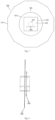
Fig. 2 is a sectional view of an imaging system according to some embodiments of the present disclosure. -
Fig. 3 is a schematic diagram of ray emission of an imaging system according to some embodiments of the present disclosure. -
Fig. 4 is a partial sectional view of an imaging system according to some embodiments of the present disclosure. -
Fig. 5 is a schematic diagram of a first detector assembly and a second detector assembly according to some embodiments of the present disclosure. -
Fig. 6 is a schematic diagram of a first detector assembly and a second detector assembly according to some embodiments of the present disclosure. -
Fig. 7 is a schematic diagram of a first detector assembly and a second detector assembly according to some embodiments of the present disclosure. -
Fig. 8 is a partial sectional view of an imaging system including a second detector assembly and a blocking member according to some embodiments of the present disclosure. -
Fig. 9 is a partial sectional view of an imaging system including a second detector assembly and a blocking member according to some embodiments of the present disclosure. -
Fig. 10 is a partial sectional view of an imaging system including a second detector assembly and a blocking member according to some embodiments of the present disclosure. -
Fig. 11 is a sectional view of an imaging system including a second ray source assembly according to some embodiments of the present disclosure. - Hereinafter, embodiments of the present disclosure are described with reference to the accompanying drawings. The following detailed description and accompanying drawings are used to exemplarily illustrate the principle of the present disclosure. The present disclosure is not limited to the described preferred embodiments, and the scope of the present disclosure is defined by the claims. The present disclosure is described in detail with reference to exemplary embodiments, some of which are illustrated in the accompanying drawings. The following description is made with reference to the accompanying drawings, and unless otherwise indicated, the same reference numerals in different accompanying drawings represent the same or similar elements. The solutions described in the following exemplary embodiments do not represent all the solutions of the present disclosure. On the contrary, these solutions are only examples of systems and methods of various aspects of the present disclosure related to the appended claims.
- The imaging system and imaging method for radiographic inspection according to the embodiments of the present disclosure can be applied to medical, security inspection, industry and other fields for transmission imaging inspection of objects, human bodies, etc.
-
Fig. 1 is a schematic diagram of an imaging system according to some embodiments of the present disclosure.Fig. 2 is a sectional view of an imaging system according to some embodiments of the present disclosure.Fig. 3 is a schematic diagram of ray emission of an imaging system according to some embodiments of the present disclosure. - According to some embodiments of the present disclosure, as shown in
Fig. 1 , the imaging system for radiographic inspection includes aninspection area 100, a firstray source assembly 200, and afirst detector assembly 300. The firstray source assembly 200 is used to emit X-rays. Thefirst detector assembly 300 is used to receive X-rays emitted from the firstray source assembly 200 and transmitted through theinspection area 100 of the imaging system. According to some embodiments of the present disclosure, the firstray source assembly 200 and thefirst detector assembly 300 are arranged to surround theinspection area 100, that is, located radially outside of theinspection area 100. The imaging system is configured such that the firstray source assembly 200 and thefirst detector assembly 300 can move relative to an object under inspection in a travelling direction. - According to some embodiments of the present disclosure, the imaging system defines the
inspection area 100. In this document, "inspection area" refers to an area that the object under inspection can enter. When the object under inspection is located in theinspection area 100, the X-rays emitted from the firstray source assembly 200 can penetrate the object under inspection and be received by thefirst detector assembly 300. In an exemplary embodiment, theinspection area 100 includes a first end and a second end. In some embodiments, the object under inspection is transferred into theinspection area 100 from one of the first end and the second end, and leaves theinspection area 100 from the other one. - According to some embodiments of the present disclosure, the object under inspection includes a region of interest (ROI), which is a local region of the object under inspection. For example, when the object under inspection is a human body, the region of interest can be a local region such as the heart and lungs of the human body. According to some embodiments of the present disclosure, the
inspection area 100 includes animaging area 110 with a central axis, that is, theimaging area 110 is a local area of theinspection area 100. In this document, the "imaging area" refers to the area where the region of interest of the object under inspection can enter and is subjected to X-ray transmission inspection. The size of theimaging area 110 is set to be large enough to accommodate the region of interest of the object under inspection. In this document, the central axis of the imaging area represents the axis passing through the approximate center of a cross section of the imaging area which is perpendicular to the travelling direction (hereinafter described). In some embodiments, the inspection area and imaging area are stationary relative to the first detector assembly 300 (and thesecond detector assembly 600 as described below). In some embodiments, the inspection area and imaging area are stationary relative to the firstray source assembly 200 and the first detector assembly 300 (and the secondray source assembly 700 and thesecond detector assembly 600 as described below). - In an exemplary embodiment, as shown in
Fig. 1 , the imaging system further includes a carryingdevice 400 for carrying the object under inspection. According to some embodiments of the present disclosure, the firstray source assembly 200 and thefirst detector assembly 300 can move relative to the carryingdevice 400 in the travelling direction. Thus, the region of interest of the object under inspection can enter theimaging area 110 of theinspection area 100. In an exemplary embodiment, the carryingdevice 400 is used to transfer the object under inspection in the travelling direction to enter theinspection area 100. In an exemplary embodiment, the travelling direction is parallel to a horizontal direction. According to some embodiments of the present disclosure, the carryingdevice 400 can transfer the object under inspection back and forth in the travelling direction through theinspection area 100, that is, transfer the object under inspection back and forth in opposite directions. In some embodiments, the carryingdevice 400 transfers the object under inspection in a uniform linear movement. In an exemplary embodiment, the travelling direction is substantially parallel to the central axis of theimaging area 110. In some embodiments, the carryingdevice 400 is a conveyor belt or a loading platform. - According to some embodiments of the present disclosure, as shown in
Fig. 1 , the imaging system may further include a shieldingmember 500. In an exemplary embodiment, the shieldingmember 500 may be arranged to surround theinspection area 100 of the imaging system. In an exemplary embodiment, the firstray source assembly 200 and thefirst detector assembly 300 are arranged to surround theinspection area 100 and are located on the outside of the shieldingmember 500, that is, on a side of the shieldingmember 500 away from theinspection area 100. - In this document, "an axial direction" refers to a direction parallel to the travelling direction, "a radial direction" refers to a direction radiating outward from the central axis in a plane perpendicular to the travelling direction, and "a circumferential direction" refers to a direction perpendicular to the "radial direction" in a plane perpendicular to the travelling direction.
- The structures and arrangements of the first ray source assembly and the first detector assembly according to some embodiments of the present disclosure are described in detail below with reference to the accompanying drawings.
- According to some embodiments of the present disclosure, the first
ray source assembly 200 includes a plurality of distributedray sources 210, and each distributedray source 210 includes a plurality of first target spots. In some embodiments, each distributedray source 210 includes a separate housing to define a separate vacuum space, and includes a plurality of first target spots enclosed in the housing. In some embodiments, the plurality of first target spots of each distributedray source 210 have uniform target spot spacing. In some embodiments, the plurality of first target spots of each distributedray source 210 are distributed along a straight line. - As described above, when the first
ray source assembly 200 includes a plurality of distributedray sources 210, each distributedray source 210 defines a separate vacuum space, and therefore does not share the vacuum space with other distributedray sources 210. The vacuum spaces of different distributedray sources 210 are not connected. According to some embodiments of the present disclosure, each distributedray source 210 may be disassembled from and/or installed into the imaging system independently from other distributedray sources 210. - As described above, the plurality of first target spots in the distributed
ray source 210 have uniform target spot spacing. However, the present disclosure is not limited to this. In some embodiments, the plurality of first target spots in the distributedray source 210 can be arranged non-uniformly, that is, can have non-uniform target spot spacing. - As described above, the plurality of first target spots in each distributed
ray source 210 are arranged along a straight line. However, the present disclosure is not limited to this. In some embodiments, the plurality of first target spots in the distributedray source 210 can be arranged along an arc, a polyline, or the like. - According to some embodiments of the present disclosure, all the first target spots of the plurality of distributed
ray sources 210 of the firstray source assembly 200 are arranged in the same plane (hereinafter referred to as "a first ray source plane"), that is, the plurality of distributedray sources 210 of the firstray source assembly 200 are arranged in a coplanar manner. In this document, "the target spots are arranged in the same plane" means that the ray emitting points of the target spots are located in the same plane. In some embodiments, the first ray source plane is substantially perpendicular to the travelling direction (or the central axis). - In an exemplary embodiment, the plurality of distributed
ray sources 210 of the firstray source assembly 200 extend completely around theimaging area 110, that is, the angle by which the plurality of distributedray sources 210 of the firstray source assembly 200 continuously extend around theimaging area 110, substantially reaches 360° when viewed in the travelling direction. Thus, the plurality of distributedray sources 210 of the firstray source assembly 200 form a complete and continuous first ray source ring. In some embodiments, the first ray source ring can be a circular ring, a square ring, a rectangular ring, a polygonal ring, and the like. For example, as shown inFig. 1 , the plurality of first distributedray sources 210 of the firstray source assembly 200 form a polygonal ring. - As described above, the plurality of distributed
ray sources 210 of the firstray source assembly 200 form a complete ray source ring. However, the present disclosure is not limited to this. In some embodiments, the ray source ring formed by the plurality of distributedray sources 210 of the firstray source assembly 200 can be incomplete, that is, includes a gap. In some embodiments, the plurality of distributedray sources 210 of the firstray source assembly 200 are divided into multiple segments, and the distributedray sources 210 of different segments can be spaced apart from each other around theimaging area 110. In an exemplary embodiment, the plurality of distributedray sources 210 of the firstray source assembly 200 have a combined extension angle of greater than 180 degrees around theimaging area 110 relative to the central axis, when viewed in the travelling direction. In this document, the extension angle of each distributedray source 210 around theimaging area 110 relative to the central axis represents the angle range of all the first target spots of the corresponding distributedray source 210 relative to the imaging area 110 (relative to the central axis of the imaging area 110). When the firstray source assembly 200 includes a plurality of distributedray sources 210, the plurality of distributedray sources 210 at different scanning positions relative to theimaging area 110 can provide a combined extension angle. The term "combined extension angle" herein refers to the angle range generated by combining the respective extension angles of the plurality of distributedray sources 210 at different scanning positions relative to theimaging area 110. In some embodiments, the combined extension angle of the plurality of distributedray sources 210 at different scanning positions relative to theimaging area 110 may be continuous or discontinuous. - As described above, the plurality of distributed
ray sources 210 of the firstray source assembly 200 form a ray source ring. However, the present disclosure is not limited to this. In some embodiments, the plurality of distributedray sources 210 of the firstray source assembly 200 can extend continuously and only partially around theimaging area 110, that is, the plurality of distributedray sources 210 of the firstray source assembly 200 provide a continuous combined extension angle around theimaging area 110 relative to the central axis, and the combined extension angle is smaller than 360°. In some embodiments, the plurality of distributedray sources 210 of the firstray source assembly 200 have a continuous combined extension angle of greater than 180° and smaller than 360° relative to the central axis around theimaging area 110. - The
first detector assembly 300 is used to receive X-rays that emitted from the firstray source assembly 200 and transmit through theimaging area 110 of the imaging system. - According to some embodiments of the present disclosure, the
first detector assembly 300 includes a plurality ofdetector units 310. In some embodiments, the arrangement of the detector units in thefirst detector assembly 300 can be set according to the arrangement of the distributedray sources 210 in the firstray source assembly 200 and/or the size of the object under inspection and other factors. In some embodiments, the arrangement of the detector units in thefirst detector assembly 300 can further be cost-effective, that is, meet the imaging requirements with as few detector units as possible. - According to some embodiments of the present disclosure, each
first detector unit 310 of thefirst detector assembly 300 includes a plurality of first detector crystals. In an exemplary embodiment, eachdetector unit 310 is arranged not to block the X-rays emitted by the distributedray source 210 on the same side, and be able to receive the X-rays emitted by the distributedray sources 210 on other sides. - In an exemplary embodiment, the plurality of
first detector units 310 are arranged in the same plane (hereinafter referred to as "a detector plane"). In this document, "detector units are arranged in the same plane" means that center planes of the detector units (such as center planes of the detector crystals) are all arranged in the same plane. For example, the center planes of the plurality offirst detector units 310 are arranged in the same plane by the same positioning reference. In some embodiments, the detector plane is substantially perpendicular to the travelling direction (the central axis). In some embodiments, thefirst detector unit 310 includes a single row of detector crystals or multiple rows of detector crystals. - In some embodiments, as shown in
Fig. 2 , along the central axis (or the travelling direction), the first ray source plane of the firstray source assembly 200 is spaced apart from the detector plane of thefirst detector assembly 300 by a predetermined distance. In an exemplary embodiment, the first ray source plane of the firstray source assembly 200 is substantially parallel to the detector plane of thefirst detector assembly 300. - In an exemplary embodiment, the plurality of
first detector units 310 of thefirst detector assembly 300 extend completely around the imaging area. Thus, the plurality offirst detector units 310 form a complete and continuous first detector ring. In some embodiments, the first detector ring may be a circular ring, a square ring, a rectangular ring, a polygonal ring, or the like. For example, as shown inFig. 1 , the plurality offirst detector units 310 form a circular ring. - As described above, the plurality of
first detector units 310 form a complete detector ring. However, the present disclosure is not limited to this. In some embodiments, the detector ring formed by the plurality offirst detector units 310 may be incomplete, that is, may include a gap. In some embodiments, the plurality offirst detector units 310 are divided into multiple segments, and thefirst detector units 310 of different segments can be spaced apart from each other around the imaging area. - Each first target spot of the first
ray source assembly 200 has a ray emission range. According to some embodiments of the present disclosure, the ray emission ranges of at least some of the first target spots of the firstray source assembly 200 are selected to be able to cover theimaging area 110. In this document, the ray emission range of the target spot covering theimaging area 110 means that the ray emission range of this target spot can just cover theimaging area 110 or is slightly larger than theimaging area 110. The ray emission ranges of these first target spots of the firstray source assembly 200 may cover theinspection area 100 or may not cover theinspection area 100. In some embodiments, the ray emission range of each of these first target spots of the firstray source assembly 200 is selected such that it is insufficient to cover theinspection area 100, that is, the ray emission range of each of these first target spots is smaller than theinspection area 100. In an exemplary embodiment, the ray emission range of each first target spot of the firstray source assembly 200 can cover theimaging area 110, and optionally, the ray emission range of each first target spot is insufficient to cover theinspection area 100. Compared with the existing ray source whose ray emission range covers the entire object under inspection, the first ray source assembly according to the embodiments of the present disclosure can provide a smaller ray emission range to merely cover the imaging area, so that transmission imaging can be performed only on the imaging area and the region of interest of the object under inspection. - According to some embodiments of the present disclosure, the
imaging area 110 is defined between the first ray source plane of the firstray source assembly 200 and an outer edge of thefirst detector assembly 300 away from the firstray source assembly 200. In an exemplary embodiment, theimaging area 110 is defined as a cylindrical area. In this case, the central axis of theimaging area 110 is the rotation axis of the cylindrical area. In some embodiments, theimaging area 110 is defined to be sufficient to accommodate the region of interest of the object under inspection. In an exemplary embodiment, the imaging system is configured such that each point in theimaging area 110 can be penetrated by the X-rays from the firstray source assembly 200 and that the X-rays after penetrating the corresponding point can be detected by thefirst detector assembly 300. - The relative positions of the first ray source assembly and the first detector assembly according to some embodiments of the present disclosure are described in detail below with reference to the accompanying drawings.
Fig. 4 is a partial sectional view of an imaging system according to some embodiments of the present disclosure. - According to some embodiments of the present disclosure, as shown in
Fig. 4 , each first target spot of the firstray source assembly 200 is arranged to deflect a first deflection angle A1 towards thefirst detector unit 310 of thefirst detector assembly 300 in the travelling direction. In some embodiments, the first deflection angle is between 1° and 5°. In some embodiments, each distributedray source 210 deflects around the axis of its first target spots. In some embodiments, the firstray source assembly 200 may further include a collimator for deflecting the direction of the X-rays emitted by the distributedray source 210 of the firstray source assembly 200 towards thefirst detector assembly 300 in the travelling direction with the first deflection angle. - In some embodiments, the first deflection angle is set such that the X-rays emitted by each distributed
ray source 210 of the firstray source assembly 200 will not be blocked by thefirst detector assembly 300 before passing through the imaging area. In some embodiments, when the ray emission direction of the firstray source assembly 200 is deflected relative to thefirst detector assembly 300, the ray emission direction is not perpendicular to the central axis of the imaging area. - By deflecting the ray emission direction of the first
ray source assembly 200 relative to thefirst detector assembly 300, the X-rays emitted by the distributedray source 210 of the firstray source assembly 200 can avoid thedetector units 310 of thefirst detector assembly 300 on the same side, and also can be received by thedetector units 310 of thefirst detector assembly 200 on other sides. - In some embodiments, the
first detector assembly 300 is arranged to be located at the radial inner side of the firstray source assembly 200 when viewed along the travelling direction (or the central axis). In other words, thefirst detector assembly 300 is arranged closer to the central axis of theimaging area 110 than the firstray source assembly 200. - In some embodiments, when viewed along the central axis (or the travelling direction), the carrying
device 400 is arranged to be located at the radial inner side of thefirst detector assembly 300, and thefirst detector assembly 300 is arranged to be located at the radial inner side of the firstray source assembly 200. Thus, as shown inFig. 1 , the firstray source assembly 200, thefirst detector assembly 300 and the carryingdevice 400 are arranged sequentially from outside to inside. - According to some embodiments of the present disclosure, the imaging system may further have a position adjustment function to adjust a position of the region of interest of the object under inspection relative to the
imaging area 110. For example, when the region of interest of the object under inspection is not completely located in theimaging area 110, by means of the position adjustment function, the region of interest of the object under inspection can be moved to be completely located in theimaging area 110. - In some embodiments, the carrying
device 400 is configured to be able to adjust the position of the region of interest of the object under inspection relative to theimaging area 110. In some embodiments, the firstray source assembly 200 is configured to be able to rotate within a predetermined range relative to the imaging area 110 (or the carrying device 400) when viewed in the travelling direction, so as to adjust the position of the region of interest of the object under inspection relative to theimaging area 110. Thus, the region of interest of the object under inspection can be located within theimaging area 110 by the adjustment. - The ray emission control according to some embodiments of the present disclosure is described in detail below with reference to the accompanying drawings.
- According to some embodiments of the present disclosure, the imaging system may further include a ray source control device (not shown). In some embodiments, the ray source control device can be configured to control the ray emission of the first
ray source assembly 200, such as emission sequence, emission frequency, emission current, and the like of the target spots. - According to some embodiments of the present disclosure, the ray source control device is configured such that when the region of interest of the object under inspection is at least partially located in the
imaging area 110, the plurality of distributedray sources 210 of the firstray source assembly 200 simultaneously emit X-rays from at least two first target spots to theimaging area 110. Therefore, more than two first target spots in the first ray source plane of the firstray source assembly 200 simultaneously emit X-rays. Therefore, the imaging system according to the embodiments of the present disclosure can improve the ray emission frequency, especially without increasing the occupied volume of the imaging system and the cost of additional detectors. - In some embodiments, the ray source control device is configured such that the first
ray source assembly 200 simultaneously emit X-rays from at least two first target spots to theimaging area 110 each time the firstray source assembly 200 is controlled to emit X-rays. In this case, each X-ray emission of the firstray source assembly 200 is simultaneous X-ray emission from multiple target spots. - In some embodiments, among the at least two first target spots of the first
ray source assembly 200 that simultaneously emit X-rays to theimaging area 110, the ray emission range of each first target spot can cover theimaging area 110, and the detector crystals of thefirst detector assembly 300 corresponding to the ray emission ranges of any two first target spots do not coincide with each other. By making the ray emission range of each first target spot of the firstray source assembly 200 cover theimaging area 110, the imaging system can perform transmission imaging only on theimaging area 110 and the region of interest of the object under inspection located therein, thereby reducing the occupied volume and cost of the imaging system. By making the detector crystals corresponding to the first target spots simultaneously emitting X-rays do not coincide with each other, signal acquisition without mutual interference can be performed while multiple target spots are simultaneously beamed out, which can help the subsequent image reconstruction and improve the transmission scanning efficiency. As shown inFig. 3 , the firstray source assembly 200 can simultaneously emit X-rays from six first target spots. - The ray emission mode of the first
ray source assembly 200 of the imaging system according to some embodiments of the present disclosure is described below. - In some embodiments, the first
ray source assembly 200 includes a total of N first target spots, and all the N first target spots are divided into M groups, with M<N/2. Each group includes the same number of first target spots. The first target spots in each group come from different distributedray sources 210 respectively. The first target spots in each group do not coincide with each other (that is, each first target spot belongs to only one group). In each group, the detector crystals of thefirst detector assembly 300 corresponding to the ray emission ranges of the respective first target spots do not coincide with each other. The ray source control device controls all the first target spots in one group to simultaneously emit X-rays, and makes the M groups of first target spots to emit X-rays in turn. - In some embodiments, the first
ray source assembly 200 includes a total of N first target spots, and all the N first target spots are divided into M groups, with M<N/2. Each group includes the same or different number of first target spots, and each group includes at least one first target spot (that is, the number of first target spots in each group can be one). The first target spots in each group come from different distributedray sources 210 respectively. The first target spots in each group do not coincide with each other (that is, each first target spot belongs to only one group). In each group, the detector crystals of thefirst detector assembly 300 corresponding to the ray emission ranges of the respective first target spots do not coincide with each other. The ray source control device controls all the first target spots in one group to simultaneously emit X-rays, and makes the M groups of first target spots to emit X-rays in turn. - In some embodiments, the first
ray source assembly 200 includes a total of N first target spots, and all the N first target spots are divided into M groups, with M<N/2. Each group includes the same number of first target spots. The first target spots in each group come from different distributedray sources 210 respectively. The first target spots in each group can be partially coincident (that is, one first target spot can belong to two or more groups at the same time). In each group, the detector crystals of thefirst detector assembly 300 corresponding to the ray emission ranges of the respective first target spots do not coincide with each other. The ray source control device controls all the first target spots in one group to simultaneously emit X-rays, and makes the M groups of first target spots to emit X-rays in turn. - The three ray emission modes of the imaging system are exemplarity described above. However, the present disclosure is not limited to this. According to the embodiments of the present disclosure, the imaging system may further have other ray emission modes. When there are more than two first target spots in the first ray source plane of the first
ray source assembly 200 that can simultaneously emit X-rays, the ray emission modes of the imaging system can be combined according to the number of groups of first target spots in the firstray source assembly 200, the grouping attribution of each first target spot, the emission interval and order of each group of first target spots and the like, to achieve different modes of X-ray emission. - According to some embodiments of the present disclosure, the imaging system can further be configured to reconstruct a three-dimensional scanning (CT) image of the region of interest of the object under inspection based on the detection data of the
first detector assembly 300. According to some embodiments of the present disclosure, the imaging system can adopt iterative reconstruction algorithm, analytical reconstruction algorithm, or the like, or a combination of different reconstruction algorithms, when reconstructing the three-dimensional scanning image of the region of interest of the object under inspection. - When the ray emission range of the first target spot of the first
ray source assembly 200 only covers the region of interest and the region of interest is completely located inside the object under inspection, the projection data may be truncated, and in this case, the imaging of the region of interest of the object under inspection belongs to an internal problem of CT. Compared with the image reconstruction when the entire object under inspection is covered by the ray emission range, there is a problem that the solution of the CT internal problem is not unique in theory. - To solve the above problem, in some implementation cases, except the first target spot (also called a target spot with small fan angle) of which the ray emission range only covers the
imaging area 110 while does not cover theentire inspection area 100, the firstray source assembly 200 can further include a second target spot (also called a target spot with large fan angle), of which the ray emission range can cover theinspection area 100. - According to some embodiments of the present disclosure, the first
ray source assembly 200 further includes at least one second target spot (the target spot with large fan angle). The ray emission range of the second target spot is selected to be able to cover theinspection area 100. In some embodiments, thefirst detector assembly 300 is further configured to receive X-rays emitted from the second target spot of the firstray source assembly 200 and transmitted through theinspection area 100. In an exemplary embodiment, when one distributedray source 210 of the firstray source assembly 200 includes the second target spot, the distributedray source 210 including both the first target spot and the second target spot can arrange each target spot in the same way as the distributedray source 210 including only the first target spot. - In some embodiments, the ray source control device is configured such that the second target spot does not emit X-rays when the first target spot of the first
ray source assembly 200 emits X-rays, and that the first target spot does not emit X-rays when the second target spot of the firstray source assembly 200 emits X-rays. Therefore, the target spot with large fan angle and the target spot with small fan angle of the imaging system emit X-rays separately. - In some embodiments, the first
ray source assembly 200 includes a plurality of second target spots. The ray source control device is configured such that the firstray source assembly 200 simultaneously emits X-rays from at least two second target spots to the inspection area. In some embodiments, among the at least two second target spots of the firstray source assembly 200 that simultaneously emit X-rays to the inspection area, the first detector crystals corresponding to the ray emission ranges of any two second target spots do not coincide with each other. Therefore, the firstray source assembly 200 can include more than two second target spots simultaneously emitting X-rays. In some embodiments, a plurality of second target spots of the firstray source assembly 200 are uniformly distributed. For example, assuming that the firstray source assembly 200 includes a total of 9 target spots, wherein the first, fourth, and seventh target spots can be the second target spots, and the remaining second, third, fifth, sixth, eighth, and ninth target spots can be the first target spots as described above. - The ray emission mode of the first
ray source assembly 200 including the second target spot according to some embodiments of the present disclosure is described below. In some embodiments, the firstray source assembly 200 includes N1 first target spots and N2 second target spots. The ray source control device can divide N1 first target spots into M groups (M<N1/2) by referring to any ray emission mode as described above, and control the M groups of first target spots and the N2 second target spots to emit X-rays in a predetermined sequence. The ray source control device is configured such that the second target spots do not emit X-rays when the first target spots of the firstray source assembly 200 emit X-rays, and that the first target spots do not emit X-rays when the second target spots of the firstray source assembly 200 emit X-rays. In each group of first target spots, the detector crystals of thefirst detector assembly 300 corresponding to the ray emission ranges of the respective first target spots do not coincide with each other. When the firstray source assembly 200 simultaneously emits X-rays from at least two second target spots to theinspection area 100, the first detector crystals corresponding to the ray emission ranges of the second target spots that simultaneously emits X-rays do not coincide with each other. - By using the above configuration, the target spots with large fan angle can be used to image the entire object under inspection, which is helpful to avoid or solve the internal problem of CT; meanwhile, the target spots with small fan angle can be used to improve the imaging quality of the region of interest.
- According to the above embodiments, the plurality of first target spots of the first
ray source assembly 200 can simultaneously emit X-rays, and optionally the plurality of second target spots of the firstray source assembly 200 can also simultaneously emit X-rays. Since multiple target spots emit X-rays simultaneously, the X-rays emitted by the respective target spots and the scattered signals generated by the object under inspection will superimpose on each other and interact each other, which may reduce the signal-to-noise ratio of the first detector assembly and thus affect the imaging quality. - In order to correct the scattered signals, according to some embodiments of the present disclosure, the imaging system can further include a
second detector assembly 600 for receiving the X-rays scattered from the object under inspection. According to some embodiments of the present disclosure, thesecond detector assembly 600 is arranged to surround theinspection area 100, that is, located at the radial outer side of theinspection area 100. In some embodiments, thesecond detector assembly 600 is stationary relative to thefirst detector assembly 300. -
Fig. 4 shows an imaging system including a second detector assembly according to some embodiments of the present disclosure. In some embodiments, thesecond detector assembly 600 includes a plurality ofsecond detector units 610. In an exemplary embodiment, the plurality ofsecond detector units 610 of thesecond detector assembly 600 are arranged corresponding to the plurality offirst detector units 310 of thefirst detector assembly 300, preferably by one-to-one correspondence. According to some embodiments of the present disclosure, thesecond detector units 610 are arranged not to receive main X-rays emitted from the firstray source assembly 200, but to receive the X-rays scattered by the object under inspection. - In an exemplary embodiment, each
second detector unit 610 includes a plurality of second detector crystals. Thesecond detector crystals 611 of eachsecond detector unit 610 are arranged side by side with thefirst detector crystals 311 of the correspondingfirst detector unit 310. In this document, "arranged side by side" means that the corresponding first detector crystals and the second detector crystals are in roughly the same radial and circumferential positions when viewed in the travelling direction. Along the travelling direction (or the central axis), the correspondingsecond detector crystals 611 and thefirst detector crystals 311 are arranged to contact or be spaced apart from each other, which will be described in detail below with reference to the accompanying drawings. - In some embodiments, along the travelling direction (or the central axis), the second detector crystals of each
second detector unit 610 are spaced apart from the first detector crystals of the correspondingfirst detector unit 310, so that thesecond detector unit 610 does not receive the main X-rays emitted from the firstray source assembly 200. Thus, thesecond detector units 610 of thesecond detector assembly 600 are arranged outside of the ray emission ranges of the first target spots of the firstray source assembly 200. -
Fig. 5 is a schematic diagram of a first detector assembly and a second detector assembly according to some embodiments of the present disclosure.Fig. 6 is a schematic diagram of a first detector assembly and a second detector assembly according to some embodiments of the present disclosure. As shown inFigs. 5 and 6 , thesecond detector crystals 611 of the second detector unit are spaced apart from thefirst detector crystals 311 of the corresponding first detector unit along the travelling direction (or the central axis). - In some embodiments, the second detector crystals of each
second detector unit 610 and the first detector crystals of the correspondingfirst detector unit 310 are arranged to contact each other along the travelling direction (or the central axis). In an exemplary embodiment, the imaging system further includes a blocking member arranged such that thesecond detector unit 610 does not receive the main X-rays emitted from the firstray source assembly 200. Because the second detector crystals are arranged immediately adjacent to the first detector crystals, and thus may receive some of the main X-rays. By providing the blocking member, thesecond detector unit 610 can be prevented from receiving the main X-rays, so as to improve the detection accuracy of the second detector assembly and the detection accuracy of the corrected transmission X-ray signals. - Hereinafter, the blocking member according to some embodiments of the present disclosure will be described with reference to the accompanying drawings.
-
Fig. 7 is a schematic diagram of a first detector assembly and a second detector assembly according to some embodiments of the present disclosure.Fig. 8 is a partial sectional view of an imaging system including a second detector assembly and a blocking member according to some embodiments of the present disclosure. As shown inFigs. 7 and8 , thesecond detector crystals 611 of thesecond detector unit 610 and thefirst detector crystals 311 of the correspondingfirst detector unit 310 are arranged immediately adjacent each other in the travelling direction. Along the travelling direction (or the central axis), the blockingmember 620 is arranged between thesecond detector crystals 611 of thesecond detector unit 610 and thefirst detector crystals 311 of thefirst detector unit 310 adjacent each other. In some embodiments, the blockingmember 620 is arranged to directly contact thesecond detector unit 610 and/or thesecond detector unit 310, such as directly contact the radial inner surface (the upper surface shown inFig. 8 ) of thesecond detector unit 610 and/or thesecond detector unit 310. In the embodiments shown inFigs. 7 and8 , the blockingmember 620 is a vertical blocking member, that is, it extends substantially in a vertical direction when viewed in the circumferential direction. -
Fig. 9 is a partial sectional view of an imaging system including a second detector assembly and a blocking member according to some embodiments of the present disclosure.Fig. 10 is a partial sectional view of an imaging system including a second detector assembly and a blocking member according to some embodiments of the present disclosure. As shown inFigs. 9 and10 , the second detector crystals of thesecond detector unit 610 and the first detector crystals of the correspondingfirst detector unit 310 are arranged immediately adjacent each other in the travelling direction. The blockingmember 620 is arranged to be spaced apart from, that is, not in direct contact with thesecond detector unit 610 and thefirst detector unit 310. As required, the blockingmember 620 can be arranged farther away from thesecond detector unit 610 and the first detector unit 310 (as shown inFig. 9 ), or closer to thesecond detector unit 610 and the first detector unit 310 (as shown inFig. 10 ). In the embodiments shown inFigs. 9 and10 , the blockingmember 620 is a horizontal blocking member, that is, it extends substantially in the horizontal direction when viewed in the circumferential direction. - As described above, when the
second detector crystals 611 of thesecond detector unit 610 and thefirst detector crystals 311 of the correspondingfirst detector unit 310 contact each other in the travelling direction, the blocking member is provided. However, the present disclosure is not limited to this. It should be understood that when thesecond detector crystals 611 of thesecond detector unit 610 and thefirst detector crystals 311 of the correspondingfirst detector unit 310 are arranged to be spaced apart from each other, the blocking member can also be provided. - Some embodiments of the blocking member are exemplarity described above. However, the present disclosure is not limited to this. It should be understood that as long as the blocking member can prevent the
second detector unit 610 from receiving the main X-rays, the blocking member can be arranged in any structure and form. - In some embodiments, as shown in
Figs. 5 and 7 , the number ofsecond detector crystals 611 of each second detector unit is equal to the number offirst detector crystals 311 of the corresponding first detector unit. Thus, for each column offirst detector crystals 311 of thefirst detector unit 310, one column (at least one) ofsecond detector crystals 611 for receiving the scattered signals are correspondingly provided. - The scatter correction mode according to some embodiments of the present disclosure is exemplarily described below. Assuming that the readings of the respective columns of
first detector crystals 311 of thefirst detector unit 310 are pl, p2, p3... respectively, and the readings of the respective columns ofsecond detector crystals 611 in of thesecond detector unit 610 are q, and considering that the scattered signal is a low-frequency signal and the width of the detection crystal is small, the transmission X-ray signals after the scatter correction can be expressed as p1-q, p2-q, p3-q. - In some embodiments, as shown in
Fig. 6 , the number ofsecond detector crystals 611 of each second detector unit is less than the number offirst detector crystals 311 of the corresponding first detector unit. For example, thesecond detector crystals 611 of thesecond detector unit 610 are spaced apart from each other along a length direction of thefirst detector unit 310. For example, based on the readings of the respective columns ofsecond detector crystals 611, the calculated values of the scattered signals of the respective columns offirst detector crystals 311 at the place where thesecond detector crystal 611 is not provided, can be obtained by means of interpolation or fitting, and the scatter signal correction can be performed accordingly. - As described above, the imaging system includes the first
ray source assembly 200 with the first target spots arranged in the first ray source plane. However, the present disclosure is not limited to this.Fig. 11 is a sectional view of an imaging system including a second ray source assembly according to some embodiments of the present disclosure. In some embodiments, as shown inFig. 11 , the imaging system further includes a secondray source assembly 700 for emitting X-rays. When the imaging system includes the secondray source assembly 700, thefirst detector assembly 300 is further configured to receive X-rays emitted from the secondray source assembly 700 and transmitted through theinspection area 100, especially theimaging area 110 of the imaging system. According to some embodiments of the present disclosure, when the object under inspection is located in theinspection area 100, the X-rays emitted from the secondray source assembly 700 can penetrate the object under inspection and be received by thefirst detector assembly 300. - According to some embodiments of the present disclosure, the second
ray source assembly 700 includes a plurality of distributed ray sources, and each distributed ray source includes a plurality of third target spots. Each distributed ray source of the secondray source assembly 700 may have the same structure, configuration and arrangement as the distributedray source 210 of the firstray source assembly 200 according to any of the above embodiments. The third target spot of the secondray source assembly 700 may have the same structure, configuration and arrangement as the first target spot of the firstray source assembly 200 according to any of the above embodiments. - Each third target spot of the second
ray source assembly 700 has a ray emission range. According to some embodiments of the present disclosure, the ray emission ranges of at least some of the third target spots of the secondray source assembly 700 are selected to be able to cover theimaging area 110. In some embodiments, the ray emission range of each of these third target spots of the secondray source assembly 700 is selected to be insufficient to cover theinspection area 100, that is, the ray emission range of each of these third target spots is smaller than theinspection area 100. In an exemplary embodiment, the ray emission range of each third target spot of the secondray source assembly 700 can cover theimaging area 110, and optionally, the ray emission range of each third target spot is insufficient to cover theinspection area 100. - According to some embodiments of the present disclosure, all the third target spots of the plurality of distributed ray sources of the second
ray source assembly 700 are arranged in the same plane (hereinafter referred to as "a second ray source plane"), that is, the plurality of distributed ray sources of the secondray source assembly 700 are arranged in the same plane. In some embodiments, the second ray source plane is substantially perpendicular to the travelling direction (or the central axis). In some embodiments, the second ray source plane of the secondray source assembly 700 is spaced apart from the detector plane of thefirst detector assembly 300 by a predetermined distance along the travelling direction (or the central axis). - According to some embodiments of the present disclosure, the first ray source plane of the first
ray source assembly 200, the detector plane of thefirst detector assembly 300, and the second ray source plane of the secondray source assembly 700 are distributed sequentially along the travelling direction (or the central axis). In an exemplary embodiment, for example, as shown inFig. 11 , the firstray source assembly 200 and the secondray source assembly 700 are respectively arranged on two sides of thefirst detector assembly 300 along the travelling direction (or the central axis). Thus, the imaging system according to some embodiments of the present disclosure includes two ray source planes, which are respectively located on two sides of the detector plane. - In an exemplary embodiment, the first ray source plane, the detector plane and the second ray source plane are basically parallel to each other. In some embodiments, the first ray source plane, the detector plane, and the second ray source plane are substantially perpendicular to the travelling direction (or the central axis).
- According to some embodiments of the present disclosure, when the imaging system further includes the second
ray source assembly 700, theimaging area 110 is defined to be located between the first ray source plane of the firstray source assembly 200 and the second ray source plane of the secondray source assembly 700. In an exemplary embodiment, theimaging area 110 is defined as a cylindrical area. In some embodiments, theimaging area 110 is defined to be sufficient to accommodate the region of interest of the object under inspection. - According to some embodiments of the present disclosure, the first
ray source assembly 200, thefirst detector assembly 300, and the secondray source assembly 700 can move together relative to the carryingdevice 400 in the travelling direction. - According to some embodiments of the present disclosure, each target spot of the second
ray source assembly 700 is arranged to deflect a second deflection angle towards thefirst detector unit 310 of thefirst detector assembly 300 in the travelling direction. In some embodiments, the second deflection angle is between 1 degrees and 5 degrees. In some embodiments, each distributed ray source of the secondray source assembly 700 deflects around the axis of its target spots. In some embodiments, the secondray source assembly 700 may further include a collimator for deflecting the direction of the X-rays emitted by the distributed ray sources of the secondray source assembly 700 towards thefirst detector assembly 300 in the travelling direction with the second deflection angle. In some embodiments, the second deflection angle is set such that the X-rays emitted by each distributed ray source of the secondray source assembly 700 will not be blocked by thefirst detector assembly 300 before passing through the imaging area. - It should be understood that since the first
ray source assembly 200 and the secondray source assembly 700 are respectively arranged on two sides of thefirst detector assembly 300, the X-rays emitted by the firstray source assembly 200 and the X-rays emitted by the secondray source assembly 700 deflect opposite each other. In an exemplary embodiment, the first deflection angle is equal to the second deflection angle. - According to some embodiments of the present disclosure, when the imaging system further includes the second
ray source assembly 700, the ray source control device is further configured to control the ray emission of the secondray source assembly 700. - In some embodiments, the ray source control device is configured such that when the region of interest of the object under inspection is at least partially located in the
imaging area 110, the plurality of distributed ray sources of the secondray source assembly 700 simultaneously emit X-rays from at least two third target spots to theimaging area 110. Among the at least two third target spots of the secondray source assembly 700 simultaneously emitting X-rays to theimaging area 110, the ray emission range of each third target spot can cover theimaging area 110, and the detector crystals of thefirst detector assembly 300 corresponding to the ray emission ranges of any two third target spots do not coincide with each other. Therefore, more than two target spots in the second ray source plane emit X-rays simultaneously. According to some embodiments of the present disclosure, the ray source control device can be configured to control the ray emission of the secondray source assembly 700, such as emission sequence, emission frequency, emission current, and the like of the target spots. - According to some embodiments of the present disclosure, the ray source control device is configured such that at least one first target spot of the first
ray source assembly 200 and at least one third target spot of the secondray source assembly 700 simultaneously emit X-rays to theimaging area 110 when the region of interest of the object under inspection is at least partially located in theimaging area 110. In this case, the firstray source assembly 200 and the secondray source assembly 700 of the imaging system can emit X-rays from at least two target spots (at least one first target spot and at least one third target spot). Therefore, the imaging system can further improve the ray emission frequency and scanning efficiency. - In some embodiments, when at least one first target spot of the first
ray source assembly 200 and at least one third target spot of the secondray source assembly 700 simultaneously emit X-rays to theimaging area 110, the detector crystal of thefirst detector assembly 300 corresponding to the ray emission range of the first target spot of the firstray source assembly 200 and the detector crystal of thefirst detector assembly 300 corresponding to the ray emission range of the third target spot of the secondray source assembly 700 do not coincide with each other. - Some exemplary structures, configurations, and arrangements of the second
ray source assembly 700 are described above. However, the present disclosure is not limited to this. It should be understood that any embodiment described herein involving the firstray source assembly 200 can be equally applied to the secondray source assembly 700. - An imaging method according to some embodiments of the present disclosure is described in detail below. According to some embodiments of the present disclosure, the imaging method can be implemented using any of the above described imaging systems.
- Taking the imaging system including the first
ray source assembly 200 and thefirst detector assembly 300 as an example, an imaging method according to some embodiments of the present disclosure is described below. However, it should be understood that the imaging system for implementing the imaging method according to the embodiments of the present disclosure can further include a secondray source assembly 700. - In step S10, the object under inspection is loaded on the carrying
device 400 of the imaging system. - In step S20, the first
ray source assembly 200 and thefirst detector assembly 300 are made to move relative to the carryingdevice 400 in the travelling direction, so that the region of interest of the object under inspection can enter theimaging area 110, and at the same time the firstray source assembly 200 is made to emit X-rays and the X-rays are made to pass through theimaging area 110 and are received by thefirst detector assembly 300. In some embodiments, the object under inspection is transferred in the travelling direction through the carryingdevice 400. - In the process of the first
ray source assembly 200 emitting X-rays, the plurality of distributedray sources 210 of the firstray source assembly 200 are made to simultaneously emit X-rays from at least two first target spots to theimaging area 110. Among the at least two target spots of the firstray source assembly 200 that simultaneously emit X-rays to theimaging area 110, the ray emission range of each target spot can cover theimaging area 110, and the detector crystals of thefirst detector assembly 300 corresponding to the ray emission ranges of any two target spots do not coincide with each other. - According to some embodiments of the present disclosure, the imaging method can further adjust the position of the region of interest of the object under inspection relative to the
imaging area 110 through the position adjustment function of the imaging system. For example, when the region of interest of the object under inspection is not completely located in theimaging area 110, the region of interest of the object under inspection can be moved to be completely located in theimaging area 110 by means of the position adjustment function of the imaging system. - In some embodiments, the imaging method further includes adjusting the position of the region of interest of the object under inspection relative to the
imaging area 110 by the carryingdevice 400 after the object under inspection is loaded on the carryingdevice 400 in step S10. In some embodiments, the imaging method further includes after the object under inspection is loaded on the carryingdevice 400 in step S10, rotating the firstray source assembly 200 relative to the imaging area 110 (or the carrying device 400) within a predetermined range when viewed in the travelling direction, so as to adjust the position of the region of interest of the object under inspection relative to theimaging area 110. Thus, the imaging method can make the region of interest of the object under inspection be located within theimaging area 110 through adjustment. - According to some embodiments of the present disclosure, the imaging method can further provide a second target spot (a target spot with large fan angle) whose ray emission range can cover the
inspection area 100 to solve potential CT internal problems. It should be understood that any embodiment herein involving a second target spot can be applied to the imaging method. - In some embodiments, in the step S20 described above, the step of the first
ray source assembly 200 emitting X-rays further includes emitting X-rays from the second target spot of the firstray source assembly 200. The ray emission range of the second target spot is selected to be able to cover theinspection area 100. In some embodiments, when the first target spot of the firstray source assembly 200 emits X-rays, the second target spot does not emit X-rays, and when the second target spot of the firstray source assembly 200 emits X-rays, the first target spot does not emit X-rays. - According to some embodiments of the present disclosure, the imaging method can further include step S30: reconstructing a three-dimensional scanning (CT) image of the region of interest of the object under inspection based on the detection data of the
first detector assembly 300. In some embodiments, the imaging method can further include recognizing the object under inspection and providing the recognition result after reconstructing the three-dimensional scanning image of the object under inspection. In some embodiments, the imaging method may further include displaying the three-dimensional scanning image and/or recognition results. - In some embodiments, the imaging method can further use the
second detector assembly 600 according to the above embodiments of the present disclosure to correct the scattered signals. It should be understood that any embodiments herein involving the second detector assembly can be applied to the imaging method. In the above step S30, the imaging method reconstructs the three-dimensional scanning image of the region of interest of the object under inspection based on the detection data of thefirst detector assembly 300 and thesecond detector assembly 600. Thus, the signal-to-noise ratio of the first detector assembly can be improved and thus the imaging quality can be improved. - In some embodiments, before performing the step S10, the imaging method can further preload or produce configuration information or correction information, such as background data, air data, and the like.
- In the imaging method according to some embodiments of the present disclosure, other embodiments of the used imaging system are described above and incorporated into the embodiments of the imaging method accordingly, and will not be repeated here.
- Although the present disclosure has been described with reference to exemplary embodiments, it should be understood that the present disclosure is not limited to the construction and method of the above embodiments. On the contrary, the present disclosure is intended to cover various modifications and equivalent configurations. In addition, although various elements and method steps of the disclosure are shown in various exemplary combinations and configurations, other combinations including more and fewer elements or methods fall within the scope of the present disclosure.
Claims (35)
- An imaging system for radiographic inspection, comprising:an inspection area, wherein an object under inspection can enter the inspection area, the inspection area comprises an imaging area, a region of interest of the object under inspection can enter the imaging area, and the region of interest is a local region of the object under inspection;a first ray source assembly for emitting X-rays, wherein the first ray source assembly comprises a plurality of distributed ray sources, each distributed ray source comprises a plurality of first target spots, and all the first target spots of the first ray source assembly are arranged in a first ray source plane;a first detector assembly for receiving X-rays emitted from the first ray source assembly and transmitted through the imaging area of the imaging system, wherein the first detector assembly comprises a plurality of first detector units, each first detector unit comprises a plurality of first detector crystals, the plurality of first detector units are arranged in a detector plane, and the detector plane and the first ray source plane are spaced apart from each other by a predetermined distance in a travelling direction of the object under inspection; anda ray source control device configured such that, when the region of interest is at least partially located in the imaging area, the first ray source assembly simultaneously emits X-rays from at least two first target spots to the imaging area ,wherein among the at least two first target spots of the first ray source assembly that simultaneously emit X-rays to the imaging area, a ray emission range of each first target spot can cover the imaging area, and the first detector crystals corresponding to the ray emission ranges of any two first target spots do not coincide with each other.
- The imaging system according to claim 1, further comprising a carrying device for carrying the object under inspection, wherein the imaging system is configured such that the first ray source assembly and the first detector assembly can move relative to the carrying device in the travelling direction, so that the region of interest of the object under inspection can enter the imaging area.
- The imaging system according to claim 2, wherein the carrying device is configured to be able to transfer the object under inspection in the travelling direction.
- The imaging system according to claim 2 or 3, wherein the carrying device is further configured to be able to adjust a position of the region of interest of the object under inspection relative to the imaging area, so that the region of interest of the object under inspection is located within the imaging area.
- The imaging system according to claim 1 or 2, wherein the imaging area is located between the first ray source plane and an outer edge of the first detector assembly away from the first ray source assembly, wherein the imaging area is defined to be sufficient to accommodate the region of interest.
- The imaging system according to claim 5, wherein the imaging area is defined as a cylindrical area with a central axis.
- The imaging system according to claim 6, wherein the travelling direction is substantially parallel to the central axis.
- The imaging system according to claim 1 or 2, wherein the detector plane and the first ray source plane are parallel to each other.
- The imaging system according to claim 1 or 2, wherein when viewed in the travelling direction, the plurality of distributed ray sources of the first ray source assembly are configured to have a combined extension angle of greater than 180 degrees around the imaging area.
- The imaging system according to claim 9, wherein the plurality of distributed ray sources of the first ray source assembly are configured to extend completely around the imaging area to form a first ray source ring.
- The imaging system according to claim 1 or 2, wherein the ray emission range of each first target spot of the first ray source assembly is selected to be insufficient to cover the inspection area.
- The imaging system according to claim 1 or 2, wherein each first target spot of the first ray source assembly is arranged to deflect a first deflection angle towards the first detector unit of the first detector assembly in the travelling direction.
- The imaging system according to claim 12, wherein the first deflection angle is between 1 degree and 5 degrees.
- The imaging system according to claim 2 or 3, wherein when viewed in the travelling direction, the first ray source assembly is configured to be able to rotate relative to the carrying device within a predetermined range to adjust a position of the region of interest of the object under inspection relative to the imaging area, so that the region of interest of the object under inspection is located within the imaging area.
- The imaging system according to claim 11, wherein the first ray source assembly further comprises at least one second target spot, and a ray emission range of the second target spot is selected to be able to cover the inspection area,
wherein the ray source control device is further configured such that the second target spot does not emit X-rays when the first target spot of the first ray source assembly emits X-rays, and that the first target spot does not emit X-rays when the second target spot of the first ray source assembly emits X-rays. - The imaging system according to claim 15, wherein the first ray source assembly comprises a plurality of second target spots, wherein the ray source control device is configured such that the first ray source assembly can simultaneously emit X-rays from at least two second target spots to the inspection area,
wherein among the at least two second target spots of the first ray source assembly simultaneously emitting X-rays to the inspection area, the first detector crystals corresponding to the ray emission ranges of any two second target spots do not coincide with each other. - The imaging system according to claim 2 or 3, wherein when viewed in the travelling direction, the first detector assembly is arranged at a radial inner side of the first ray source assembly.
- The imaging system according to claim 17, wherein the first detector assembly is configured to extend completely around the imaging area to form a detector ring.
- The imaging system according to claim 18, wherein the first detector unit of the first detector assembly comprises a single row of first detector crystals or a plurality of rows of first detector crystals.
- The imaging system according to claim 17, further comprising a second detector assembly for receiving X-rays scattered from the object under inspection, wherein the second detector assembly comprises a plurality of second detector units, and each second detector unit comprises a plurality of second detector crystals.
- The imaging system according to claim 20, wherein the plurality of second detector units of the second detector assembly are arranged correspondingly to the plurality of first detector units of the first detector assembly.
- The imaging system according to claim 21, wherein the imaging system further comprises a blocking member arranged such that the second detector units do not receive main X-rays emitted from the first ray source assembly.
- The imaging system according to claim 21, wherein the second detector crystals of each second detector unit are spaced apart from the first detector crystals of the corresponding first detector unit in the travelling direction, so that the second detector unit does not receive main X-rays emitted from the first ray source assembly.
- The imaging system according to claim 21, wherein the number of second detector crystals of each second detector unit is equal to the number of first detector crystals of the corresponding first detector unit; or,
the number of second detector crystals of each second detector unit is less than the number of first detector crystals of the corresponding first detector unit. - The imaging system according to claim 2, further comprising:a second ray source assembly for emitting X-rays, wherein the second ray source assembly comprises a plurality of distributed ray sources, each distributed ray source comprises a plurality of third target spots, all the third target spots of the second ray source assembly are arranged in a second ray source plane, and the detector plane and the second ray source plane are spaced apart from each other by a predetermined distance in the travelling direction,wherein the first detector assembly is further configured to receive the X-rays emitted from the second ray source assembly and transmitted through the imaging area of the imaging system,wherein the first ray source plane, the detector plane and the second ray source plane are distributed sequentially in the travelling direction,wherein the ray source control device is configured such that when the region of interest is at least partially located in the imaging area, the second ray source assembly simultaneously emit X-rays from at least two third target spots to the imaging area, andamong the at least two third target spots of the second ray source assembly that simultaneously emit X-rays to the imaging area, a ray emission range of each third target spot can cover the imaging area, and the first detector crystals corresponding to the ray emission ranges of any two third target spots do not coincide with each other.
- The imaging system according to claim 25, wherein the imaging system is configured such that the first ray source assembly, the first detector assembly and the second ray source assembly can move relative to the carrying device in the travelling direction, so that the region of interest of the object under inspection can enter the imaging area.
- The imaging system according to claim 25, wherein the imaging area is located between the first ray source plane and the second ray source plane, and wherein the imaging area is defined to be sufficient to accommodate the region of interest.
- The imaging system according to claim 27, wherein the imaging area is defined as a cylindrical area with a central axis.
- The imaging system according to claim 25, wherein the detector plane, the first ray source plane and the second ray source plane are parallel to each other.
- The imaging system according to claim 25, wherein the ray source control device is configured such that at least one first target spot of the first ray source assembly and at least one third target spot of the second ray source assembly simultaneously emit X-rays to the imaging area when the region of interest of the object under inspection is at least partially located in the imaging area, and
wherein when at least one first target spot of the first ray source assembly and at least one third target spot of the second ray source assembly simultaneously emit X-rays to the imaging area, the detector crystals of the first detector assembly corresponding to the ray emission range of the first target spot of the first ray source assembly and the detector crystals of the first detector assembly corresponding to the ray emission range of the third target spot of the second ray source assembly do not coincide with each other. - The imaging system according to claim 1 or 2, wherein the imaging system is further configured to construct a three-dimensional scanning image of the region of interest of the object under inspection based on the detection data of the first detector assembly.
- An imaging method using the imaging system according to claim 2, the imaging method comprising:(a) loading the object under inspection on the carrying device of the imaging system; and(b) making the first ray source assembly and the first detector assembly of the imaging system move relative to the carrying device in the travelling direction, so that the region of interest of the object under inspection can enter the imaging area, and meanwhile make the first ray source assembly emit X-rays and make the X-rays transmit through the imaging area to be received by the first detector assembly,wherein the step of the first ray source assembly emitting X-rays comprises: making the first ray source assembly simultaneously emit X-rays from at least two first target spots to the imaging area, andwherein among the at least two first target spots of the first ray source assembly that simultaneously emit X-rays to the imaging area, the ray emission range of each first target spot can cover the imaging area, and the first detector crystals corresponding to the ray emission ranges of any two first target spots do not coincide with each other.
- The imaging method according to claim 32, further comprising adjusting a position of the region of interest of the object under inspection relative to the imaging area by the carrying device after the object under inspection is loaded on the carrying device in the step (a), so that the region of interest of the object under inspection is located within the imaging area.
- The imaging method according to claim 32, further comprising after the object under inspection is loaded on the carrying device in the step (a), rotating the first ray source assembly relative to the carrying device within a predetermined range when viewed in the travelling direction, to adjust a position of the region of interest of the object under inspection relative to the imaging area so that the region of interest of the object under inspection is located within the imaging area.
- The imaging method according to claim 32, wherein the step of the first ray source assembly emitting X-rays further comprises: emitting X-rays from the second target spot of the first ray source assembly, and the ray emission range of the second target spot is selected to be able to cover the inspection area,
wherein when the first target spot of the first ray source assembly emits X-rays, the second target spot does not emit X-rays, and when the second target spot of the first ray source assembly emits X-rays, the first target spot does not emit X-rays.
Applications Claiming Priority (2)
| Application Number | Priority Date | Filing Date | Title |
|---|---|---|---|
| CN202111204463.6A CN115105110B (en) | 2021-10-15 | 2021-10-15 | Imaging system and method for radiographic inspection |
| PCT/CN2022/124449 WO2023061340A1 (en) | 2021-10-15 | 2022-10-10 | Imaging system and method for radiographic examination |
Publications (3)
| Publication Number | Publication Date |
|---|---|
| EP4393406A1 true EP4393406A1 (en) | 2024-07-03 |
| EP4393406A4 EP4393406A4 (en) | 2025-01-08 |
| EP4393406B1 EP4393406B1 (en) | 2025-09-24 |
Family
ID=83325430
Family Applications (1)
| Application Number | Title | Priority Date | Filing Date |
|---|---|---|---|
| EP22880277.3A Active EP4393406B1 (en) | 2021-10-15 | 2022-10-10 | Imaging system and method for radiographic inspection |
Country Status (6)
| Country | Link |
|---|---|
| US (1) | US12437397B2 (en) |
| EP (1) | EP4393406B1 (en) |
| CN (2) | CN119184720B (en) |
| ES (1) | ES3057526T3 (en) |
| PL (1) | PL4393406T3 (en) |
| WO (1) | WO2023061340A1 (en) |
Families Citing this family (8)
| Publication number | Priority date | Publication date | Assignee | Title |
|---|---|---|---|---|
| CN119184720B (en) * | 2021-10-15 | 2025-09-30 | 清华大学 | Imaging system and method for radiographic inspection |
| CN116602701A (en) * | 2023-04-17 | 2023-08-18 | 清华大学 | Five-in-one imaging device based on distributed light source and distributed detector |
| CN116297569B (en) * | 2023-04-28 | 2023-09-05 | 杭州睿影科技有限公司 | Object detection method, system and processing equipment based on x-rays |
| CN117110325A (en) * | 2023-09-20 | 2023-11-24 | 苏州矩浪科技有限公司 | Motion control methods, devices, equipment and storage media |
| CN118216940B (en) * | 2024-03-20 | 2025-04-18 | 清华大学 | Distributed ray source CT imaging system and imaging method |
| CN119224018B (en) * | 2024-12-04 | 2025-02-28 | 清华大学 | CT imaging system |
| CN119224019B (en) * | 2024-12-04 | 2025-03-07 | 清华大学 | Imaging method of CT imaging system |
| CN120253905A (en) * | 2025-06-04 | 2025-07-04 | 赣州好朋友科技股份有限公司 | A spliced annular X-ray imaging system and intelligent ore dressing machine |
Family Cites Families (27)
| Publication number | Priority date | Publication date | Assignee | Title |
|---|---|---|---|---|
| US4442489A (en) * | 1979-06-16 | 1984-04-10 | U.S. Philips Corporation | Device for computed tomography |
| US6385278B1 (en) * | 2000-04-28 | 2002-05-07 | Ge Medical Systems Global Technology Company, Llc | Method and apparatus for region of interest multislice CT scan |
| US6876724B2 (en) * | 2000-10-06 | 2005-04-05 | The University Of North Carolina - Chapel Hill | Large-area individually addressable multi-beam x-ray system and method of forming same |
| CA2407004C (en) * | 2001-02-23 | 2008-02-19 | Mitsubishi Heavy Industries, Ltd. | X-ray ct apparatus |
| US6661866B1 (en) | 2002-08-28 | 2003-12-09 | Ge Medical Systems Global Technology Company, Llc | Integrated CT-PET system |
| JP4314008B2 (en) * | 2002-10-01 | 2009-08-12 | 株式会社東芝 | X-ray CT scanner |
| WO2004080310A1 (en) * | 2003-03-13 | 2004-09-23 | Philips Intellectual Property & Standards Gmbh | Computerized tomographic imaging system |
| CN101472524B (en) * | 2006-06-22 | 2011-05-25 | 皇家飞利浦电子股份有限公司 | Multi-tube imaging system scatter correction |
| CN101561405B (en) * | 2008-04-17 | 2011-07-06 | 清华大学 | Straight-line track scanning imaging system and method |
| KR101373006B1 (en) * | 2011-12-27 | 2014-03-13 | 삼성전자주식회사 | The method and apparatus for adjusting a range of x-ray emission |
| CN102764137B (en) * | 2012-07-27 | 2014-06-04 | 苏州生物医学工程技术研究所 | Static CT (computed tomography) scanner and scattering X-photon correction method thereof |
| JP2014226376A (en) * | 2013-05-23 | 2014-12-08 | 株式会社東芝 | X-ray ct device |
| PL228457B1 (en) * | 2013-08-30 | 2018-03-30 | Univ Jagiellonski | TOF-PET/CT hybrid tomograph |
| CN104470178A (en) * | 2013-09-18 | 2015-03-25 | 清华大学 | X-ray device and CT equipment with the X-ray device |
| CN104374783B (en) * | 2013-12-26 | 2017-06-16 | 清华大学 | CT system and its method |
| CN104749648A (en) * | 2013-12-27 | 2015-07-01 | 清华大学 | Multi-energy spectrum static CT apparatus |
| CN104897703B (en) * | 2014-03-04 | 2018-09-28 | 清华大学 | Check equipment, method and system |
| CN104101910A (en) | 2014-07-04 | 2014-10-15 | 清华大学 | Distributed radiation source-based X-ray backscattering channel type vehicle security system and method |
| CN105374654B (en) * | 2014-08-25 | 2018-11-06 | 同方威视技术股份有限公司 | Electron source, x-ray source, the equipment for having used the x-ray source |
| CN104483711B (en) * | 2014-12-17 | 2020-02-21 | 同方威视技术股份有限公司 | Radiation imaging system based on distributed light source |
| CN106783484B (en) * | 2016-12-15 | 2018-10-16 | 清华大学 | Photocathode distribution X-ray generator and CT equipment with the device |
| CN118248507A (en) * | 2017-09-18 | 2024-06-25 | 同方威视技术股份有限公司 | Distributed X-ray light source and control method thereof and CT equipment |
| DE102019107348A1 (en) * | 2018-03-22 | 2019-09-26 | Werth Messtechnik Gmbh | Apparatus and method for computer tomographic measurement of workpieces |
| CN211381407U (en) * | 2019-09-12 | 2020-09-01 | 北京纳米维景科技有限公司 | Static real-time CT imaging system with paired source rings |
| US11058369B2 (en) * | 2019-11-15 | 2021-07-13 | GE Precision Healthcare LLC | Systems and methods for coherent scatter imaging using a segmented photon-counting detector for computed tomography |
| CN111759335B (en) * | 2020-05-29 | 2023-05-02 | 东软医疗系统股份有限公司 | Method, device, electronic equipment, and storage medium for acquiring multi-energy spectral imaging data |
| CN119184720B (en) * | 2021-10-15 | 2025-09-30 | 清华大学 | Imaging system and method for radiographic inspection |
-
2021
- 2021-10-15 CN CN202411318154.5A patent/CN119184720B/en active Active
- 2021-10-15 CN CN202111204463.6A patent/CN115105110B/en active Active
-
2022
- 2022-10-10 PL PL22880277.3T patent/PL4393406T3/en unknown
- 2022-10-10 ES ES22880277T patent/ES3057526T3/en active Active
- 2022-10-10 WO PCT/CN2022/124449 patent/WO2023061340A1/en not_active Ceased
- 2022-10-10 EP EP22880277.3A patent/EP4393406B1/en active Active
- 2022-10-17 US US17/967,039 patent/US12437397B2/en active Active
Also Published As
| Publication number | Publication date |
|---|---|
| CN119184720A (en) | 2024-12-27 |
| PL4393406T3 (en) | 2026-02-23 |
| ES3057526T3 (en) | 2026-03-03 |
| CN119184720B (en) | 2025-09-30 |
| CN115105110B (en) | 2024-11-08 |
| US12437397B2 (en) | 2025-10-07 |
| WO2023061340A1 (en) | 2023-04-20 |
| EP4393406B1 (en) | 2025-09-24 |
| CN115105110A (en) | 2022-09-27 |
| EP4393406A4 (en) | 2025-01-08 |
| US20230124325A1 (en) | 2023-04-20 |
Similar Documents
| Publication | Publication Date | Title |
|---|---|---|
| US12437397B2 (en) | Imaging system and method for radiographic inspection | |
| US6956925B1 (en) | Methods and systems for multi-modality imaging | |
| CN114947911B (en) | Imaging system for radiographic inspection | |
| US6735271B1 (en) | Electron beam computed tomographic scanner system with helical or tilted target, collimator, and detector components to eliminate cone beam error and to scan continuously moving objects | |
| EP2963455B1 (en) | X-ray backscattering safety inspection system having distributed x-ray source and method using the same | |
| US8530849B2 (en) | Electron beam scanner | |
| US20050226363A1 (en) | Stationary computed tomography system and method | |
| EP4628879A1 (en) | Ct scanning system and method | |
| US12510497B2 (en) | Inspection system and method | |
| CN115113289A (en) | Inspection system and method | |
| CN115097535A (en) | Inspection system and method | |
| JPWO2002065917A1 (en) | X-ray CT system | |
| US6792077B2 (en) | Collimation system for dual slice EBT scanner | |
| US10541061B2 (en) | System for generating and collimating an X-ray beam | |
| IL114348A (en) | Detector signal integration in volumetric ct scanner detector arrays | |
| US12571936B2 (en) | Inspection system and inspection method | |
| US7688939B2 (en) | Object rotation for CT data acquisition | |
| CN219915424U (en) | CT scanning system | |
| US20240418901A1 (en) | Static or quasi-static multi-view or 3d inspection of cargo | |
| US8625738B2 (en) | Radiation therapy and scanning system | |
| HK40101144A (en) | Imaging system for radiographic examination | |
| CN119534497B (en) | CT imaging system | |
| CN119224018A (en) | CT imaging system |
Legal Events
| Date | Code | Title | Description |
|---|---|---|---|
| STAA | Information on the status of an ep patent application or granted ep patent |
Free format text: STATUS: THE INTERNATIONAL PUBLICATION HAS BEEN MADE |
|
| PUAI | Public reference made under article 153(3) epc to a published international application that has entered the european phase |
Free format text: ORIGINAL CODE: 0009012 |
|
| STAA | Information on the status of an ep patent application or granted ep patent |
Free format text: STATUS: REQUEST FOR EXAMINATION WAS MADE |
|
| 17P | Request for examination filed |
Effective date: 20240327 |
|
| AK | Designated contracting states |
Kind code of ref document: A1 Designated state(s): AL AT BE BG CH CY CZ DE DK EE ES FI FR GB GR HR HU IE IS IT LI LT LU LV MC ME MK MT NL NO PL PT RO RS SE SI SK SM TR |
|
| A4 | Supplementary search report drawn up and despatched |
Effective date: 20241206 |
|
| RIC1 | Information provided on ipc code assigned before grant |
Ipc: A61B 6/03 20060101AFI20241202BHEP |
|
| DAV | Request for validation of the european patent (deleted) | ||
| DAX | Request for extension of the european patent (deleted) | ||
| GRAP | Despatch of communication of intention to grant a patent |
Free format text: ORIGINAL CODE: EPIDOSNIGR1 |
|
| STAA | Information on the status of an ep patent application or granted ep patent |
Free format text: STATUS: GRANT OF PATENT IS INTENDED |
|
| INTG | Intention to grant announced |
Effective date: 20250701 |
|
| GRAS | Grant fee paid |
Free format text: ORIGINAL CODE: EPIDOSNIGR3 |
|
| GRAA | (expected) grant |
Free format text: ORIGINAL CODE: 0009210 |
|
| STAA | Information on the status of an ep patent application or granted ep patent |
Free format text: STATUS: THE PATENT HAS BEEN GRANTED |
|
| AK | Designated contracting states |
Kind code of ref document: B1 Designated state(s): AL AT BE BG CH CY CZ DE DK EE ES FI FR GB GR HR HU IE IS IT LI LT LU LV MC ME MK MT NL NO PL PT RO RS SE SI SK SM TR |
|
| REG | Reference to a national code |
Ref country code: GB Ref legal event code: FG4D |
|
| REG | Reference to a national code |
Ref country code: CH Ref legal event code: EP |
|
| REG | Reference to a national code |
Ref country code: DE Ref legal event code: R096 Ref document number: 602022022093 Country of ref document: DE |
|
| REG | Reference to a national code |
Ref country code: IE Ref legal event code: FG4D |
|
| REG | Reference to a national code |
Ref country code: SE Ref legal event code: TRGR |
|
| REG | Reference to a national code |
Ref country code: CH Ref legal event code: U11 Free format text: ST27 STATUS EVENT CODE: U-0-0-U10-U11 (AS PROVIDED BY THE NATIONAL OFFICE) Effective date: 20251230 |
|
| PG25 | Lapsed in a contracting state [announced via postgrant information from national office to epo] |
Ref country code: NO Free format text: LAPSE BECAUSE OF FAILURE TO SUBMIT A TRANSLATION OF THE DESCRIPTION OR TO PAY THE FEE WITHIN THE PRESCRIBED TIME-LIMIT Effective date: 20251224 |
|
| REG | Reference to a national code |
Ref country code: LT Ref legal event code: MG9D |
|
| PGFP | Annual fee paid to national office [announced via postgrant information from national office to epo] |
Ref country code: AT Payment date: 20260113 Year of fee payment: 4 |
|
| PG25 | Lapsed in a contracting state [announced via postgrant information from national office to epo] |
Ref country code: FI Free format text: LAPSE BECAUSE OF FAILURE TO SUBMIT A TRANSLATION OF THE DESCRIPTION OR TO PAY THE FEE WITHIN THE PRESCRIBED TIME-LIMIT Effective date: 20250924 |
|
| PG25 | Lapsed in a contracting state [announced via postgrant information from national office to epo] |
Ref country code: HR Free format text: LAPSE BECAUSE OF FAILURE TO SUBMIT A TRANSLATION OF THE DESCRIPTION OR TO PAY THE FEE WITHIN THE PRESCRIBED TIME-LIMIT Effective date: 20250924 |
|
| PGFP | Annual fee paid to national office [announced via postgrant information from national office to epo] |
Ref country code: FR Payment date: 20251117 Year of fee payment: 4 |
|
| PG25 | Lapsed in a contracting state [announced via postgrant information from national office to epo] |
Ref country code: GR Free format text: LAPSE BECAUSE OF FAILURE TO SUBMIT A TRANSLATION OF THE DESCRIPTION OR TO PAY THE FEE WITHIN THE PRESCRIBED TIME-LIMIT Effective date: 20251225 |
|
| PGFP | Annual fee paid to national office [announced via postgrant information from national office to epo] |
Ref country code: SE Payment date: 20251118 Year of fee payment: 4 Ref country code: CH Payment date: 20251230 Year of fee payment: 4 |
|
| PG25 | Lapsed in a contracting state [announced via postgrant information from national office to epo] |
Ref country code: LV Free format text: LAPSE BECAUSE OF FAILURE TO SUBMIT A TRANSLATION OF THE DESCRIPTION OR TO PAY THE FEE WITHIN THE PRESCRIBED TIME-LIMIT Effective date: 20250924 |
|
| PG25 | Lapsed in a contracting state [announced via postgrant information from national office to epo] |
Ref country code: BG Free format text: LAPSE BECAUSE OF FAILURE TO SUBMIT A TRANSLATION OF THE DESCRIPTION OR TO PAY THE FEE WITHIN THE PRESCRIBED TIME-LIMIT Effective date: 20250924 |
|
| PG25 | Lapsed in a contracting state [announced via postgrant information from national office to epo] |
Ref country code: RS Free format text: LAPSE BECAUSE OF FAILURE TO SUBMIT A TRANSLATION OF THE DESCRIPTION OR TO PAY THE FEE WITHIN THE PRESCRIBED TIME-LIMIT Effective date: 20251224 |
|
| REG | Reference to a national code |
Ref country code: NL Ref legal event code: MP Effective date: 20250924 |
|
| PGFP | Annual fee paid to national office [announced via postgrant information from national office to epo] |
Ref country code: ES Payment date: 20251212 Year of fee payment: 4 |
|
| PG25 | Lapsed in a contracting state [announced via postgrant information from national office to epo] |
Ref country code: NL Free format text: LAPSE BECAUSE OF FAILURE TO SUBMIT A TRANSLATION OF THE DESCRIPTION OR TO PAY THE FEE WITHIN THE PRESCRIBED TIME-LIMIT Effective date: 20250924 |
|
| REG | Reference to a national code |
Ref country code: CH Ref legal event code: R17 Free format text: ST27 STATUS EVENT CODE: U-0-0-R10-R17 (AS PROVIDED BY THE NATIONAL OFFICE) Effective date: 20260218 |
|
| REG | Reference to a national code |
Ref country code: ES Ref legal event code: FG2A Ref document number: 3057526 Country of ref document: ES Kind code of ref document: T3 Effective date: 20260303 |
|
| REG | Reference to a national code |
Ref country code: AT Ref legal event code: MK05 Ref document number: 1839755 Country of ref document: AT Kind code of ref document: T Effective date: 20250924 |
|
| PG25 | Lapsed in a contracting state [announced via postgrant information from national office to epo] |
Ref country code: SM Free format text: LAPSE BECAUSE OF FAILURE TO SUBMIT A TRANSLATION OF THE DESCRIPTION OR TO PAY THE FEE WITHIN THE PRESCRIBED TIME-LIMIT Effective date: 20250924 |
|
| PGFP | Annual fee paid to national office [announced via postgrant information from national office to epo] |
Ref country code: DE Payment date: 20251223 Year of fee payment: 4 |
|
| PG25 | Lapsed in a contracting state [announced via postgrant information from national office to epo] |
Ref country code: AT Free format text: LAPSE BECAUSE OF FAILURE TO SUBMIT A TRANSLATION OF THE DESCRIPTION OR TO PAY THE FEE WITHIN THE PRESCRIBED TIME-LIMIT Effective date: 20250924 |
|
| PG25 | Lapsed in a contracting state [announced via postgrant information from national office to epo] |
Ref country code: RO Free format text: LAPSE BECAUSE OF FAILURE TO SUBMIT A TRANSLATION OF THE DESCRIPTION OR TO PAY THE FEE WITHIN THE PRESCRIBED TIME-LIMIT Effective date: 20250924 Ref country code: IT Free format text: LAPSE BECAUSE OF FAILURE TO SUBMIT A TRANSLATION OF THE DESCRIPTION OR TO PAY THE FEE WITHIN THE PRESCRIBED TIME-LIMIT Effective date: 20250924 |
|
| PG25 | Lapsed in a contracting state [announced via postgrant information from national office to epo] |
Ref country code: IS Free format text: LAPSE BECAUSE OF FAILURE TO SUBMIT A TRANSLATION OF THE DESCRIPTION OR TO PAY THE FEE WITHIN THE PRESCRIBED TIME-LIMIT Effective date: 20260124 |
|
| PG25 | Lapsed in a contracting state [announced via postgrant information from national office to epo] |
Ref country code: CZ Free format text: LAPSE BECAUSE OF FAILURE TO SUBMIT A TRANSLATION OF THE DESCRIPTION OR TO PAY THE FEE WITHIN THE PRESCRIBED TIME-LIMIT Effective date: 20250924 Ref country code: PT Free format text: LAPSE BECAUSE OF FAILURE TO SUBMIT A TRANSLATION OF THE DESCRIPTION OR TO PAY THE FEE WITHIN THE PRESCRIBED TIME-LIMIT Effective date: 20260126 |
|
| PGFP | Annual fee paid to national office [announced via postgrant information from national office to epo] |
Ref country code: PL Payment date: 20251119 Year of fee payment: 4 |
|
| PG25 | Lapsed in a contracting state [announced via postgrant information from national office to epo] |
Ref country code: EE Free format text: LAPSE BECAUSE OF FAILURE TO SUBMIT A TRANSLATION OF THE DESCRIPTION OR TO PAY THE FEE WITHIN THE PRESCRIBED TIME-LIMIT Effective date: 20250924 Ref country code: SK Free format text: LAPSE BECAUSE OF FAILURE TO SUBMIT A TRANSLATION OF THE DESCRIPTION OR TO PAY THE FEE WITHIN THE PRESCRIBED TIME-LIMIT Effective date: 20250924 |